JP5517397B2 - Image processing method and image processing apparatus - Google Patents
Image processing method and image processing apparatus Download PDFInfo
- Publication number
- JP5517397B2 JP5517397B2 JP2007038430A JP2007038430A JP5517397B2 JP 5517397 B2 JP5517397 B2 JP 5517397B2 JP 2007038430 A JP2007038430 A JP 2007038430A JP 2007038430 A JP2007038430 A JP 2007038430A JP 5517397 B2 JP5517397 B2 JP 5517397B2
- Authority
- JP
- Japan
- Prior art keywords
- marker
- image
- markers
- definition information
- flag
- Prior art date
- Legal status (The legal status is an assumption and is not a legal conclusion. Google has not performed a legal analysis and makes no representation as to the accuracy of the status listed.)
- Expired - Fee Related
Links
Images


Classifications
-
- G—PHYSICS
- G06—COMPUTING OR CALCULATING; COUNTING
- G06T—IMAGE DATA PROCESSING OR GENERATION, IN GENERAL
- G06T7/00—Image analysis
- G06T7/80—Analysis of captured images to determine intrinsic or extrinsic camera parameters, i.e. camera calibration
-
- G—PHYSICS
- G06—COMPUTING OR CALCULATING; COUNTING
- G06T—IMAGE DATA PROCESSING OR GENERATION, IN GENERAL
- G06T7/00—Image analysis
- G06T7/70—Determining position or orientation of objects or cameras
- G06T7/73—Determining position or orientation of objects or cameras using feature-based methods
-
- G—PHYSICS
- G06—COMPUTING OR CALCULATING; COUNTING
- G06V—IMAGE OR VIDEO RECOGNITION OR UNDERSTANDING
- G06V10/00—Arrangements for image or video recognition or understanding
- G06V10/20—Image preprocessing
- G06V10/24—Aligning, centring, orientation detection or correction of the image
- G06V10/245—Aligning, centring, orientation detection or correction of the image by locating a pattern; Special marks for positioning
-
- G—PHYSICS
- G06—COMPUTING OR CALCULATING; COUNTING
- G06T—IMAGE DATA PROCESSING OR GENERATION, IN GENERAL
- G06T2200/00—Indexing scheme for image data processing or generation, in general
- G06T2200/24—Indexing scheme for image data processing or generation, in general involving graphical user interfaces [GUIs]
-
- G—PHYSICS
- G06—COMPUTING OR CALCULATING; COUNTING
- G06T—IMAGE DATA PROCESSING OR GENERATION, IN GENERAL
- G06T2207/00—Indexing scheme for image analysis or image enhancement
- G06T2207/10—Image acquisition modality
- G06T2207/10016—Video; Image sequence
-
- G—PHYSICS
- G06—COMPUTING OR CALCULATING; COUNTING
- G06T—IMAGE DATA PROCESSING OR GENERATION, IN GENERAL
- G06T2207/00—Indexing scheme for image analysis or image enhancement
- G06T2207/30—Subject of image; Context of image processing
- G06T2207/30204—Marker
- G06T2207/30208—Marker matrix
Landscapes
- Engineering & Computer Science (AREA)
- Physics & Mathematics (AREA)
- General Physics & Mathematics (AREA)
- Theoretical Computer Science (AREA)
- Computer Vision & Pattern Recognition (AREA)
- Multimedia (AREA)
- User Interface Of Digital Computer (AREA)
- Length Measuring Devices By Optical Means (AREA)
- Image Processing (AREA)
- Studio Devices (AREA)
- Image Analysis (AREA)
Description
本発明は、現実空間に存在する指標の位置姿勢を求める技術に関するものである。 The present invention relates to a technique for obtaining the position and orientation of an index existing in a real space.
高品質な複合現実感を提供するための重要な技術の一つとして、現実空間と仮想空間との位置合わせ技術がある。位置合わせ技術としては従来から様々な手法が提案されているが、それらの中でも指標を撮影した画像(指標画像)からカメラの位置姿勢を計算(キャリブレーション)する方法がコストや使い勝手の点から広く利用されている。 One important technique for providing high-quality mixed reality is a technique for aligning a real space and a virtual space. Various methods have been proposed as alignment techniques. Among them, the method of calculating (calibrating) the camera's position and orientation from an image (index image) obtained by shooting an index is widely used from the viewpoint of cost and usability. It's being used.
これらの手法の多くは、空間におけるすべての指標の位置や姿勢が既知であることを前提としており、指標の位置や姿勢を予め測定し、入力する作業が必要となる。指標には、人為的マーカ(以後、マーカ)や自然特徴が一般的に用いられている。マーカを用いた場合には、配置するマーカの数が多くなればなるほど、人が手作業で測定を行うことは非現実的な作業となる。 Many of these methods are based on the premise that the positions and orientations of all the indices in the space are known, and it is necessary to measure and input the positions and orientations of the indices in advance. As the index, an artificial marker (hereinafter referred to as a marker) or a natural feature is generally used. When markers are used, the more markers that are placed, the more unrealistic it is for a person to perform manual measurements.
位置合わせ処理を可能とする空間の範囲を広げるためには、多数のマーカを広範囲に設置することが必要となる。従ってこれら多数の広範囲に設置されたマーカの位置姿勢を効率よくかつ高精度に測定する手段が求められている。 In order to expand the range of the space in which the alignment process can be performed, it is necessary to install a large number of markers in a wide range. Therefore, there is a need for means for efficiently and highly accurately measuring the position and orientation of these many widely installed markers.
近年、マーカを撮影した画像から、マーカ同士の相対位置姿勢をキャリブレーションする方法が提案されている(非特許文献1参照)。 In recent years, a method for calibrating the relative position and orientation of markers from an image obtained by photographing the markers has been proposed (see Non-Patent Document 1).
この方法によって全てのマーカ同士の相対位置姿勢を求めた後、任意のマーカの世界座標系における位置姿勢を決定すれば、世界座標系におけるすべてのマーカの位置姿勢を求めることが可能となった。 After obtaining the relative positions and orientations of all the markers by this method, the positions and orientations of all the markers in the world coordinate system can be obtained by determining the positions and orientations of the arbitrary markers in the world coordinate system.
この方法における位置合わせ処理に必要な作業およびキャリブレーション処理の概要は以下のとおりである。 The work required for the alignment process in this method and the outline of the calibration process are as follows.
(1.1) マーカを作成し、位置合わせ処理を行う空間内に設置する。 (1.1) Create a marker and place it in the space where the alignment process is performed.
(1.2) 世界座標系における位置姿勢が決定されているマーカ(基準マーカ)の位置姿勢を入力する。 (1.2) The position and orientation of a marker (reference marker) whose position and orientation are determined in the world coordinate system are input.
(1.3) マーカを撮影する。 (1.3) Shoot the marker.
(1.4) キャリブレーションを行う。 (1.4) Perform calibration.
(ア) 複数のマーカが含まれる画像から、ある1つのマーカとカメラとの相対位置姿勢を計算する。 (A) The relative position and orientation of a certain marker and the camera are calculated from an image including a plurality of markers.
(イ) 別のマーカとカメラとの相対位置姿勢を計算する。 (B) Calculate the relative position and orientation of another marker and the camera.
(ウ) 2つのマーカ間の相対位置姿勢を計算する。 (C) Calculate the relative position and orientation between the two markers.
(エ) これをすべての複数のマーカが含まれる画像について行い、すべてのマーカ間の相対位置姿勢を計算する。 (D) This is performed for an image including all of the plurality of markers, and the relative positions and orientations between all the markers are calculated.
(オ) 基準マーカから、基準マーカ以外のすべてのマーカ(相対マーカ)の絶対位置姿勢を計算する。 (E) Calculate the absolute position and orientation of all markers (relative markers) other than the reference marker from the reference marker.
(1.5) キャリブレーションにより位置姿勢が求められたマーカを使用して位置合わせ処理を行う。 (1.5) Alignment processing is performed using a marker whose position and orientation are obtained by calibration.
一般的な自然特徴を用いた位置合わせは、自然特徴データベースの作成、及び自然特徴データベースを用いたカメラの位置姿勢の推定、といった2つの工程から構成される(非特許文献2)。自然特徴データベースの作成は、マーカのキャリブレーションと同様に、現実空間を撮影することで得られる多数の画像を用いて行われる。自然特徴を用いた位置合わせ処理に必要な作業の概要は以下のとおりである。 General alignment using natural features is composed of two steps: creation of a natural feature database and estimation of the position and orientation of the camera using the natural feature database (Non-Patent Document 2). The creation of the natural feature database is performed using a large number of images obtained by photographing the real space, similarly to the calibration of the marker. The outline of the work necessary for the alignment processing using natural features is as follows.
(2.1) 現実空間の画像を複数撮影する。 (2.1) Take multiple images of real space.
(2.2) 画像から特徴を抽出する。 (2.2) Extract features from the image.
(2.3) ある特徴の位置を、複数の画像から求める。 (2.3) The position of a certain feature is obtained from a plurality of images.
(ア) 複数の画像間で、特徴の対応を行う。 (A) Corresponding features between multiple images.
(イ) 複数の画像間の相対位置姿勢を、上記対応に基づいて求める。 (A) The relative position and orientation between a plurality of images is obtained based on the above correspondence.
(ウ) 上記相対位置姿勢に基づいて、特徴の三次元位置を求める。 (C) The three-dimensional position of the feature is obtained based on the relative position and orientation.
(エ) 全ての抽出された特徴に対してこれを実施する。 (D) Perform this for all extracted features.
(2.4) 上記で作成された自然特徴データベースを使用して、カメラの位置姿勢を推定し、位置合わせを行う。
既存の手法では、マーカを利用した場合には、上記(1.3)の作業において撮影されたマーカ全てを上記(1.4)でキャリブレーションし、上記(1.5)の位置合わせ処理で使用していた。 In the existing method, when the marker is used, all the markers photographed in the operation (1.3) are calibrated by the above (1.4), and the alignment process of the above (1.5) is performed. I was using it.
使用するマーカの数が増えるほど、位置合わせの精度は向上するが、位置合わせ処理およびキャリブレーション処理の負荷が増大するため、使用するマーカの数は少ないほうが望ましい。操作者が、撮影時点で必要なマーカだけを撮影するように注意することで、ある程度マーカの数を少なくすることは可能である。しかし、これには操作者の経験と技術が必要となる。そのため実際には上記(1.1)〜(1.5)の作業を繰り返し行い、最適なマーカの配置と数を体験的に決定することが行われている。 As the number of markers used increases, the alignment accuracy improves. However, since the load of the alignment processing and calibration processing increases, it is desirable that the number of markers used be small. It is possible for the operator to reduce the number of markers to some extent by taking care that only the necessary markers are shot at the time of shooting. However, this requires operator experience and skills. Therefore, in practice, the above operations (1.1) to (1.5) are repeatedly performed, and the optimum arrangement and number of markers are determined empirically.
この時、既存の手法では、任意のマーカをキャリブレーションや位置合わせ処理から除外する場合には、取得した画像の全てあるいは一部を破棄し、マーカが取得画像に含まれないようにしてから再度キャリブレーションを行っていた。もしくはマーカを空間から除去した後、再度画像を取得し、キャリブレーションを行っていた。 At this time, in the existing method, when excluding any marker from the calibration and alignment processing, all or part of the acquired image is discarded, and the marker is not included in the acquired image, and then again. Calibration was in progress. Alternatively, after removing the marker from the space, the image is acquired again and calibration is performed.
また、キャリブレーションおよび位置合わせ処理を行う複数の画像処理装置を隣接した空間で使用する場合、(1.1)の作業において自分の画像処理装置が使用するために設置したマーカ以外に、隣接した画像処理装置が使用するために設置したマーカを偶然撮影する可能性が高くなる。この場合、不要な位置合わせ処理およびキャリブレーション処理が発生してしまう。 Further, when a plurality of image processing apparatuses that perform calibration and alignment processing are used in an adjacent space, in addition to the markers installed for use by the own image processing apparatus in the operation of (1.1), adjacent There is a high possibility that the marker installed for use by the image processing apparatus is accidentally photographed. In this case, unnecessary alignment processing and calibration processing occur.
さらに、自分の画像処理装置が使用するために配置したマーカのマーカIDと、隣接した画像処理装置が使用するために配置されているマーカのマーカIDが重複する可能性が存在する。この場合、キャリブレーションおよび位置合わせ処理が正しく動作しなくなってしまう。 Furthermore, there is a possibility that the marker ID of the marker arranged for use by the own image processing apparatus and the marker ID of the marker arranged for use by the adjacent image processing apparatus overlap. In this case, calibration and alignment processing will not operate correctly.
マーカIDの重複は、例えば(1.1)の作業において予備用として作成したマーカを不注意にキャリブレーションおよび位置合わせ処理を行う空間に放置したのを偶然撮影してしまうことでも発生する。また、マーカIDの重複は画像処理によるマーカの誤認識によっても発生する。 The overlap of the marker ID also occurs, for example, when the marker created for the preliminary operation in the operation (1.1) is inadvertently left in the space where the calibration and alignment processing is accidentally shot. In addition, duplication of marker IDs also occurs due to erroneous marker recognition by image processing.
マーカの誤認識はマーカに類似した被写体の撮影、マーカを撮影する装置の露出・絞り等のパラメータ、撮影環境における光の状況などの外乱により発生し、画像処理装置の操作者が十分注意しても発生しないようにすることは困難であった。 Marker misrecognition occurs due to disturbances such as shooting a subject similar to the marker, parameters such as exposure and aperture of the device that captures the marker, and light conditions in the shooting environment. It was difficult to prevent this from occurring.
既存の手法では、重複したマーカをキャリブレーションや位置合わせ処理から除外するためには、取得した画像の全てあるいは一部を破棄した後、重複したマーカ以外の全てのマーカを再撮影していた。 In the existing method, in order to exclude the duplicated marker from the calibration and alignment processing, all or a part of the acquired image is discarded, and then all the markers other than the duplicated marker are re-photographed.
一方、自然特徴を利用した場合には、上記(2.2)の作業において抽出された特徴の位置を、上記(2.3)の処理で算出し、自然特徴データベースを作成し、上記(2.4)の位置合わせ処理で使用していた。 On the other hand, when the natural feature is used, the position of the feature extracted in the operation of (2.2) is calculated by the processing of (2.3), a natural feature database is created, and the above (2) 4) was used in the alignment process.
既存の方法では、類似した特徴が数多く出現する可能性がある。この場合、自然特徴データベースの作成や、位置合わせ処理において、類似した特徴を同一の特徴として誤って対応付けることがあり、正しく動作しない危険性がある。 With existing methods, many similar features may appear. In this case, there is a risk that similar features may be mistakenly associated with each other as the same feature in the creation of the natural feature database or the alignment process, and the operation may not be performed correctly.
本発明は以上の問題に鑑みてなされたものであり、自動的もしくは半自動的にキャリブレーションおよび位置合わせ処理に使用する指標を選択する為の技術を提供することを目的とする。 The present invention has been made in view of the above problems, and an object of the present invention is to provide a technique for automatically or semi-automatically selecting an index used for calibration and alignment processing.
また、本発明の別の目的は、マーカ定義情報に応じて、キャリブレーションの実行に必要な作業を操作者に通知することで、操作者が行う位置合わせのための設定作業の負荷を軽減することにある。 Another object of the present invention is to notify the operator of work necessary for executing calibration according to the marker definition information, thereby reducing the load of setting work for alignment performed by the operator. There is.
本発明の目的を達成するために、例えば、本発明の画像処理方法は以下の構成を備える。 In order to achieve the object of the present invention, for example, an image processing method of the present invention comprises the following arrangement.
即ち、識別可能なパターンを有する複数のマーカが配された現実空間の画像を取得する取得工程と、
前記取得工程で取得した画像中のマーカのパターンから、当該マーカのIDを識別し、当該識別されたIDを所定のファイルに登録する識別工程と、
前記識別工程で識別され前記所定のファイルに登録されたID同士を比較して、識別されたIDが同一である複数のマーカを重複して配置されたマーカとして検知する検知工程と、
前記識別工程で識別されたマーカのうち、前記検知工程で検知された重複して配置されたマーカ以外のマーカの現実空間中の位置及び/若しくは姿勢を計算する計算工程と
を有することを特徴とする。
That is, an acquisition step of acquiring an image of a real space in which a plurality of markers having identifiable patterns are arranged;
An identification step of identifying the ID of the marker from the pattern of the marker in the image acquired in the acquisition step, and registering the identified ID in a predetermined file ;
A detection step of comparing the IDs identified in the identification step and registered in the predetermined file, and detecting a plurality of markers having the same identified ID as overlapping markers;
A calculation step of calculating a position and / or orientation in a real space of markers other than the overlappingly arranged markers detected in the detection step among the markers identified in the identification step, To do.
本発明の目的を達成するために、例えば、本発明の画像処理装置は以下の構成を備える。 In order to achieve the object of the present invention, for example, an image processing apparatus of the present invention comprises the following arrangement.
即ち、識別可能なパターンを有する複数のマーカが配された現実空間の画像を取得する取得手段と、
前記取得手段が取得した画像中のマーカのパターンから、当該マーカのIDを識別し、当該識別されたIDを所定のファイルに登録する識別手段と、
前記識別手段が識別し前記所定のファイルに登録したID同士を比較して、識別されたIDが同一である複数のマーカを重複して配置されたマーカとして検知する検知手段と、
前記識別手段によって識別されたマーカのうち、前記検知手段によって検知された重複して配置されたマーカ以外のマーカの現実空間中の位置及び/若しくは姿勢を計算する計算手段と
を備えることを特徴とする。
That is, an acquisition means for acquiring an image of a real space in which a plurality of markers having identifiable patterns are arranged;
Identifying means for identifying the ID of the marker from the pattern of the marker in the image obtained by the obtaining means, and registering the identified ID in a predetermined file ;
Detecting means for comparing IDs identified by the identifying means and registered in the predetermined file, and detecting a plurality of markers having the same identified ID as overlapping markers;
Calculating means for calculating a position and / or orientation in a real space of markers other than the overlappingly arranged markers detected by the detecting means among the markers identified by the identifying means, To do.
本発明の構成によれば、自動的もしくは半自動的にキャリブレーションおよび位置合わせ処理に使用するマーカを選択することができる。 According to the configuration of the present invention, a marker to be used for calibration and alignment processing can be selected automatically or semi-automatically.
以下添付図面を参照して、本発明を好適な実施形態に従って詳細に説明する。 Hereinafter, the present invention will be described in detail according to preferred embodiments with reference to the accompanying drawings.
[第1の実施形態]
本実施形態では、マーカを指標の一例として用いた場合について説明する。
[First Embodiment]
In this embodiment, a case where a marker is used as an example of an index will be described.
図1は、本実施形態で用いるマーカの構成例(フォーマット例、パターン例)を示す図である。同図に示す如く、本実施形態で用いるマーカは、4×4の小正方形でもって構成されており、更に4×4の小正方形は、4隅(blk1〜blk3,wht)、c1〜c4、x1〜x8に分類される。また、各小正方形は白か黒の何れかで塗りつぶされており、塗りつぶされた色によってビット値「0」若しくはビット値「1」を表している。例えば白で塗りつぶされている小正方形はビット値「0」を表しているし、黒で塗りつぶされている小正方形はビット値「1」を表している。 FIG. 1 is a diagram illustrating a configuration example (format example, pattern example) of a marker used in the present embodiment. As shown in the figure, the marker used in the present embodiment is configured by 4 × 4 small squares, and the 4 × 4 small squares further include four corners (blk1 to blk3, white), c1 to c4, It is classified into x1 to x8. Each small square is filled with either white or black, and represents a bit value “0” or a bit value “1” depending on the filled color. For example, a small square filled with white represents a bit value “0”, and a small square filled with black represents a bit value “1”.
先ず、4隅の小正方形(blk1〜blk3,wht)について説明する。4隅の小正方形は何れか1つが白(wht)で、残り3つが黒(blk1〜3)である。これらはマーカ座標系を定義するために使用されるものである。マーカ座標系とは、マーカ毎に定義される座標系であって、より具体的にはblk1とblk2とを結ぶ線分の方向をx座標軸の正方向、blk3とblk2とを結ぶ線分の方向をy座標軸の正方向、マーカの法線方向をz座標軸の正方向、マーカの中心位置を原点とする座標系である。図3は、マーカ座標系を示す図である。マーカの世界座標系における位置は、世界座標系におけるマーカ座標系原点の位置で決定される。また、マーカの世界座標系における姿勢は、マーカ座標系が世界座標系を基準にどのように回転しているかによって決定される。
First, small squares (blk1 to blk3, whit) at four corners will be described. Any one of the four small squares is white (wht), and the remaining three are black (
このことから、このようなマーカを撮像するカメラとマーカとの相対位置姿勢は、マーカ画像におけるマーカの形状、辺の長さ、中心位置を用いて、周知の技術により求めることができる。 From this, the relative position and orientation between the camera that images such a marker and the marker can be obtained by a known technique using the marker shape, side length, and center position in the marker image.
次に、c1〜c4、x1〜x8について説明する。x1〜x8は、マーカ固有の識別子(マーカID)を表すためのものである。x1〜x8で8ビットを表現できるので、マーカIDは0〜255の値を取ることができる。c1〜c4は検査ビットであり、画像処理による情報ビットの誤認識が発生した場合の訂正に使用される。 Next, c1 to c4 and x1 to x8 will be described. x1 to x8 are for representing an identifier (marker ID) unique to the marker. Since 8 bits can be expressed by x1 to x8, the marker ID can take a value of 0 to 255. c1 to c4 are inspection bits, and are used for correction when an information bit is erroneously recognized by image processing.
検査ビットの値は以下の式から求められる。 The value of the check bit can be obtained from the following equation.
c1=not(x1+x2+x3 +x5+x6 )
c2=not( x2+x3+x4 +x6+x7 )
c3=not( x3+x4+x5 +x7+x8)
c4=not(x1 +x4+x5+x6 +x8)
図2は、図1に示したフォーマットに従って作成された実際のマーカの一例を示す図である。上述の通り、各小正方形は白若しくは黒でもって塗りつぶされており、それぞれの小正方形は割り当てられた情報を表している。なお、マーカのサイズについては特に限定するものではないが、本実施形態では、現実空間中に配する全てのマーカの一辺の長さについては全て同じであるとする。
c1 = not (x1 + x2 + x3 + x5 + x6)
c2 = not (x2 + x3 + x4 + x6 + x7)
c3 = not (x3 + x4 + x5 + x7 + x8)
c4 = not (x1 + x4 + x5 + x6 + x8)
FIG. 2 is a diagram showing an example of an actual marker created in accordance with the format shown in FIG. As described above, each small square is filled with white or black, and each small square represents assigned information. In addition, although it does not specifically limit about the size of a marker, In this embodiment, suppose that all the lengths of one side of all the markers arranged in the real space are the same.
次に、このようなマーカの位置姿勢を求める、本実施形態に係る画像処理装置について説明する。図4は、本実施形態に係る画像処理装置の機能構成を示すブロック図である。 Next, the image processing apparatus according to the present embodiment for obtaining the position and orientation of such a marker will be described. FIG. 4 is a block diagram illustrating a functional configuration of the image processing apparatus according to the present embodiment.
同図において100は画像処理装置本体を示している。画像入力部101は、ディジタルカメラやハードディスク装置などの外部装置から供給される画像を取得する。ここで取得する画像は、図1〜3を用いて説明したマーカが複数配置された現実空間の画像である。画像入力部101は取得した画像を後段の画像取得部102に供給する。
In the figure,
画像取得部102は、画像入力部101から受けた画像を、本装置が扱うことのできるフォーマットに変更する等、様々な前処理をこの画像に対して行う。処理済みの画像は後段の画像管理部106に送出する。
The
画像管理部106は、画像取得部102から画像を受けると、これを記憶部110に格納する処理を行う。また、必要に応じて記憶部110に格納されている画像や、後述するマーカ定義情報を読み出し、指標管理部107や画像合成部111に送出する。
When the
記憶部110は、画像管理部106から受けた画像や、後述するマーカ定義情報を記憶するためのものである。
The
ここで、マーカ定義情報とは、マーカに関する様々な情報の集まりで、マーカ毎に存在する。本実施形態では、マーカ定義情報は、マーカID、マーカ状態、マーカサイズ、マーカ位置姿勢により構成されている。マーカ定義情報は、例えば、図5に示すようなテーブル形式でもって記憶部110に格納されている。
Here, the marker definition information is a collection of various information related to the marker and exists for each marker. In the present embodiment, the marker definition information includes a marker ID, a marker state, a marker size, and a marker position and orientation. The marker definition information is stored in the
図5は、それぞれのマーカに対するマーカ定義情報を登録したテーブル(マーカ定義情報テーブル)の構成例を示すブロック図である。同図に示す如く、テーブルには、それぞれのマーカについて、「マーカID」、「マーカ状態」、「マーカサイズ」、「マーカの位置、姿勢」が登録されている。 FIG. 5 is a block diagram illustrating a configuration example of a table (marker definition information table) in which marker definition information for each marker is registered. As shown in the figure, in the table, “marker ID”, “marker state”, “marker size”, and “marker position and orientation” are registered for each marker.
「マーカID」は上述の通り、マーカに記されたx1〜x8に対応するものである。即ち、マーカIDにはビット列x1〜x8が示す値が登録されている。 As described above, “marker ID” corresponds to x1 to x8 marked on the marker. That is, the values indicated by the bit strings x1 to x8 are registered in the marker ID.
「マーカ状態」は同図に示す如く、基準マーカフラグ、検出フラグ、対象フラグ、完了ステータスにより構成されている。 As shown in the figure, the “marker state” includes a reference marker flag, a detection flag, a target flag, and a completion status.
基準マーカフラグとは、マーカが基準マーカであるのか否かを示すフラグである。基準マーカフラグが「1」であれば基準マーカであることを示し、「0」であれば基準マーカではない(換言すれば相対マーカである)ことを示している。同図ではマーカID=7のマーカのみが基準マーカフラグ=1であり、このマーカのみが基準マーカであることを示している。 The reference marker flag is a flag indicating whether or not the marker is a reference marker. If the reference marker flag is “1”, it is a reference marker, and if it is “0”, it is not a reference marker (in other words, a relative marker). In the figure, only the marker with marker ID = 7 is the reference marker flag = 1, and it is shown that only this marker is the reference marker.
検出フラグとは、マーカが、画像取得部102から送出された画像から検出されたか否かを示すフラグである。検出フラグが「1」であれば検出されたことを示し、「0」であれば検出されなかったことを示す。同図では、マーカID=1,7,45,125のマーカが検出フラグ=1であり、マーカID=1,7,45,125のマーカが画像から検出されたことを示している。
The detection flag is a flag indicating whether or not the marker is detected from the image transmitted from the
対象フラグとは、マーカが位置姿勢計算対象である(即ちキャリブレーション対象である)か否かを示すフラグである。対象フラグが「1」であれば、計算対象となることを示し、「0」であれば計算対象ではないことを示す。同図では、マーカID=1,7,45のマーカが対象フラグ=1であり、マーカID=1,7,45のマーカはキャリブレーション対象であることを示している。一方、マーカID=125のマーカは対象フラグ=0であり、キャリブレーション対象ではないことを示している。 The target flag is a flag indicating whether or not the marker is a position / orientation calculation target (that is, a calibration target). If the target flag is “1”, it indicates that it is a calculation target, and if it is “0”, it indicates that it is not a calculation target. In the figure, the markers with marker ID = 1, 7, 45 are the target flag = 1, and the markers with marker ID = 1, 7, 45 are calibration targets. On the other hand, the marker with marker ID = 125 has a target flag = 0, indicating that it is not a calibration target.
完了ステータスとは、マーカのキャリブレーションが実行されたか否かを示すフラグである。完了ステータスが「1」であれば、位置姿勢計算が実行されており、「0」であれば位置姿勢計算が実行されておらず、「2」であれば、位置姿勢計算を実行したが計算に失敗して正しく位置姿勢が求められていないことを示している。同図では、マーカID=1のマーカは完了ステータス=2であり、このマーカの位置姿勢は正しく求められていない。また、マーカID=7,45のマーカは完了ステータス=1であり、これらのマーカにこれらのマーカについては正しく位置姿勢が求められている。マーカID=125のマーカの完了ステータス=0であり、このマーカについては未だ位置姿勢計算が実行されていない。 The completion status is a flag indicating whether or not marker calibration has been executed. If the completion status is “1”, the position / orientation calculation is executed. If “0”, the position / orientation calculation is not executed. If it is “2”, the position / orientation calculation is executed. This indicates that the position and orientation are not calculated correctly. In the figure, the marker with marker ID = 1 has a completion status = 2, and the position and orientation of this marker have not been determined correctly. Further, the markers with marker ID = 7, 45 have the completion status = 1, and the position and orientation of these markers are correctly determined for these markers. The completion status = 0 of the marker with marker ID = 125 is 0, and the position / orientation calculation has not yet been executed for this marker.
「マーカサイズ」は、マーカの一辺の長さを示している。上述の通り、本実施形態では、全てのマーカは一辺が同じ長さを有しているものとしている。同図では、マーカID=1,7,45,125のマーカは全て一辺が「40」となっている。 “Marker size” indicates the length of one side of the marker. As described above, in this embodiment, all the markers have the same length on one side. In the figure, all the markers with marker ID = 1, 7, 45, 125 are “40” on one side.
「マーカの位置、姿勢」はそれぞれ、マーカの世界座標系における位置、姿勢を示している。ここでマーカの姿勢は回転軸ベクトルと回転角で表現されている。すなわち世界座標系とマーカ座標系の各軸を一致させた状態で、回転軸ベクトルを中心としてマーカ座標系を右に回転させた状態を表している。 “Marker position and orientation” indicate the position and orientation of the marker in the world coordinate system, respectively. Here, the posture of the marker is expressed by a rotation axis vector and a rotation angle. That is, it represents a state in which the marker coordinate system is rotated to the right around the rotation axis vector in a state where the axes of the world coordinate system and the marker coordinate system are matched.
以上説明したテーブルのデータが記憶部110に登録されている。
The table data described above is registered in the
図4に戻って次に、指標管理部107は、記憶部110や画像管理部106から送出された情報を指標位置姿勢計算部108や指標抽出部109に送出する処理を行う。
Returning to FIG. 4, the
指標位置姿勢計算部108は、後述する処理により位置姿勢計算対象として特定されたマーカの世界座標系における位置姿勢を計算する処理を行う。指標抽出部109は、記憶部110から指標管理部107を介して受けた画像からマーカを検出する処理を行う。指標位置姿勢計算部108、指標抽出部109のそれぞれが求めた結果は指標管理部107に送出される。即ち、指標管理部107は、指標に係る様々な情報を管理している。
The index position /
画像合成部111は、画像取得部102から送出された画像上における各マーカのうち、後述する処理により位置姿勢計算対象として特定されたマーカについて、マーカIDなどのマーカ情報やマーカの輪郭形状を理解しやすくするコンピュータグラフィックス(CG)を生成する。そして、生成したCGを記憶部110から指標管理部107を介して受けた画像上に重畳する処理を行う。画像合成部111による処理後の画像は後段のユーザインターフェース管理部103に送出される。
The
ユーザインターフェース管理部103は、表示部105の表示画面上に表示する情報を管理するものであり、画像合成部111から受けた画像を表示部105に送出する。また、ユーザインターフェース管理部103は、制御部104から受けた各種の指示を受け、受けた指示に応じて上記各部を制御し、制御結果に応じた表示を表示部105の表示画面上に行う処理も行う。
The user
表示部105は、CRTや液晶画面などにより構成されており、各種の処理結果を画像や文字などでもって表示することができる。制御部104は、本装置の操作者からの操作指示を受け、ユーザインターフェース管理部103に通知する。
The
図30は、上記画像処理装置100に適用可能なコンピュータのハードウェア構成を示すブロック図である。
FIG. 30 is a block diagram showing a hardware configuration of a computer applicable to the
3001はCPUで、RAM3002やROM3003に格納されているプログラム(コンピュータプログラム)やデータを用いて本コンピュータ全体の制御を行うと共に、本コンピュータが行う後述の各処理を実行する。例えば、図4に示した画像処理装置100の構成において、画像入力部101、記憶部110、表示部105を除く各部が有する機能は、CPU3001が有する機能の一部として機能する。
3002はRAMで、外部記憶装置3006からロードされたプログラムやデータ、I/F(インターフェース)3007を介して外部(本実施形態の場合にはカメラなどの撮像装置)から取得したデータ(本実施形態の場合には撮像画像)を一時的に記憶するためのエリアを有する。更にRAM3002は、CPU3001が各種の処理を実行する際に用いるワークエリアを有する。このように、RAM3002は、各種の用途に応じて適宜エリアを提供することができる。
3003はROMで、本コンピュータの設定データやブートプログラムなどを格納する。
3004は操作部で、キーボードやマウスなどにより構成されており、本コンピュータの操作者が操作することで、各種の指示をCPU3001に対して入力することができる。
An
3005は表示部で、CRTや液晶画面等により構成されており、CPU3001による処理結果を画像や文字などでもって表示することができる。表示部3005は、図4における表示部105に相当するものである。
A
3006は外部記憶装置で、ハードディスクドライブ装置に代表される大容量情報記憶装置である。ここにはOS(オペレーティングシステム)や、上記記憶部110が保持する各種の情報(データ)、本コンピュータが行う後述の各処理をCPU3001に実行させるためのプログラムやデータが保存されている。これらのプログラムやデータはCPU3001による制御に従って適宜RAM3002にロードされる。そしてCPU3001はこのロードされたプログラムやデータを用いて処理を実行することで、本コンピュータが行う後述の各処理を実行することになる。
3007はI/Fで、本実施形態の場合には、上記マーカが複数配された現実空間を撮像する撮像装置を本コンピュータに接続するためのインターフェースとして機能するものである。この撮像装置が撮像した画像は、このI/F3007を介して本コンピュータのRAM3002や外部記憶装置3006に入力される。
3008は上述の各部を繋ぐバスである。
A
なお、本実施形態に係る画像処理装置100に適用可能なコンピュータのハードウェア構成については同図に示した構成に限定するものではなく、画像処理装置100が行う後述の各処理を実行可能な構成であれば良い。
Note that the hardware configuration of a computer applicable to the
次に、上記コンピュータ上で動作し、現実空間中に配された指標の位置姿勢を求めるために用いるGUI(グラフィカルユーザインターフェース)について説明する。図6は、このGUIの表示例を示す図である。なお、同図のGUIに係るプログラムやデータは外部記憶装置3006に保存されている。これをRAM3002にロードし、CPU3001がこのロードされたプログラムやデータを用いて処理を実行することで、同図に示した構成を有するウィンドウが表示部3005の表示画面上に表示される。これは、以下の説明で登場するその他のウィンドウについても同様である。
Next, a GUI (graphical user interface) that operates on the computer and is used to obtain the position and orientation of the index placed in the real space will be described. FIG. 6 is a diagram showing a display example of this GUI. Note that the programs and data related to the GUI shown in FIG. When this is loaded into the
なお、以下の説明では特に触れない限りは、GUIに対する操作は本コンピュータの操作者が操作部3004を用いて行うものとし、この操作によって実行される処理についてはCPU3001が行うものとする。
Unless otherwise specified in the following description, operations on the GUI are performed by an operator of the computer using the
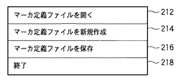
図6に示したGUIにおいて「ファイル」メニュー210を指示すると、表示部3005の表示画面上には図7に示すようなファイルメニューが表示される。図7に示したファイルメニューにおいて「マーカ定義ファイルを開く」メニュー212を指示すると、図10に示したウィンドウが表示部3005の表示画面上に表示される。図10に示したウィンドウにおいて300は、外部記憶装置3006に保存されているマーカ定義ファイルのファイル名を一覧表示するための領域であり、本コンピュータの操作者は操作部3004を用いて、この領域300内に表示されているファイル名のうち何れか1つを選択することができる。マーカ定義ファイルとは、図5に示したテーブルのデータを記録したファイルである。複数のマーカ定義ファイルを外部記憶装置3006に保存させておくと、図10に示したGUIでこれらのファイルを選択することができる。
When the “file”
ここで、操作者がファイルを1つ選択して「OK」ボタン310を指示すると、画像処理装置は同図に示したウィンドウの表示を消去した後、選択したファイルの内容に従って、図6のGUIにおける領域230内の表示を更新する。領域230内に表示されている情報の詳細については後述する。
Here, when the operator selects one file and designates an “OK”
図7のファイルメニューに戻って、「マーカ定義ファイルを新規作成」メニュー214を指示すると、表示部3005の表示画面上には図11に示すようなウィンドウが表示される。図11に示したウィンドウにおいて400は、新規作成するマーカ定義ファイルのファイル名を入力するための領域である。本コンピュータの操作者が操作部3004を用いて領域400に新規のマーカ定義ファイルのファイル名を入力後「OK」ボタン410を指示すると、画像処理装置は同図に示したウィンドウの表示を消去した後、領域400内に入力したファイル名を有するマーカ定義ファイルを外部記憶装置3006内に作成する。
Returning to the file menu of FIG. 7 and instructing the “create new marker definition file”
図7のファイルメニューに戻って、「マーカ定義ファイルを保存」メニュー216を指示すると、現在開いているマーカ定義ファイルを外部記憶装置3006に保存する処理を行う。
Returning to the file menu of FIG. 7, when a “save marker definition file”
「終了」メニュー218を指示すると、CPU3001はOSが有する周知のシャットダウン機能を用いてシャットダウンに係る処理を行い、本コンピュータのシャットダウンを行う。
When an “end”
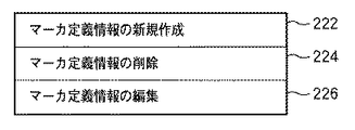
図6に示したGUIに戻って、「編集」メニュー220を指示すると、表示部3005の表示画面上には、図8に示した編集メニューが表示される。図8に示した編集メニューにおいて「マーカ定義情報の新規作成」メニュー222を指示すると、マーカ定義情報が新規に作成され、現在開いているマーカ定義ファイルに追加登録される。そして追加登録後、現在開いているマーカ定義ファイルの内容に従って、図6のGUIにおける領域230内の表示を更新する。ここで、マーカIDの重複を避けるため、新規作成するマーカ定義情報のマーカIDは、マーカ定義情報テーブルにおいて未使用の値が使用される。新規作成されたマーカ定義情報は、後述するウィンドウ上で変更することができる。
Returning to the GUI shown in FIG. 6, when the “edit”
図8の編集メニューに戻って、「マーカ定義情報の削除」メニュー224を指示すると、図6のGUIにおける領域230内で現在選択しているマーカ定義情報が、現在開いているマーカ定義ファイルから削除される。そして削除後、現在開いているマーカ定義ファイルの内容に従って、図6のGUIにおける領域230内の表示を更新する。この更新表示により、削除されたマーカ定義情報は表示されなくなる。
Returning to the editing menu of FIG. 8, when the “delete marker definition information”
「マーカ定義情報の編集」メニュー226を指示すると、図9に示すようなウィンドウが表示される。同図に示したウィンドウは、領域230内で現在選択されているマーカ定義情報の編集に使用する。250はウィンドウ本体である。
When the “edit marker definition information”
252は、現在選択されているマーカ定義情報におけるマーカIDを入力するための領域である。この領域252に入力した値が、現在選択されているマーカ定義情報におけるマーカIDとなる。
254は、現在選択されているマーカ定義情報におけるマーカ位置を入力するための領域である。この領域254に入力した値が、現在選択されているマーカ定義情報におけるマーカ位置となる。 Reference numeral 254 denotes an area for inputting a marker position in the currently selected marker definition information. The value input in this area 254 is the marker position in the currently selected marker definition information.
256は、現在選択されているマーカ定義情報におけるマーカ姿勢を入力するための領域である。この領域256に入力した値が、現在選択されているマーカ定義情報におけるマーカ姿勢となる。 An area 256 is used to input a marker posture in the currently selected marker definition information. The value input in this area 256 is the marker posture in the currently selected marker definition information.
258は、現在選択されているマーカ定義情報におけるマーカサイズを入力するための領域である。この領域258に入力した値が、現在選択されているマーカ定義情報におけるマーカサイズとなる。なお、本実施形態では、領域258に入力したマーカサイズは、全てのマーカのマーカ定義情報に反映されるものとする。
259は、現在選択されているマーカ定義情報におけるマーカ状態に含まれている基準マーカフラグを編集するためのプルダウンメニューである。このプルダウンメニュー259には「基準マーカ」、「相対マーカ」が表示され、何れかを選択することができる。操作者が「基準マーカ」を選択すれば基準マーカフラグは「1」に設定され、「相対マーカ」を選択すれば基準マーカフラグは「0」に設定される。
ただし、本実施形態では、マーカ定義ファイルにおいて基準マーカは1つのみ存在可能とする。従って、基準マーカフラグを「1」にしたマーカ定義情報が既に存在する場合、他のマーカ定義情報を操作しても「相対マーカ」しか選択することができない。 However, in this embodiment, only one reference marker can exist in the marker definition file. Accordingly, if marker definition information with the reference marker flag set to “1” already exists, only “relative marker” can be selected even if other marker definition information is operated.
251は「OK」ボタンである。これを指示することで、選択中のマーカ定義情報を、各領域252〜259に入力された各情報で更新する処理を行う。即ち、現在選択されているマーカ定義情報におけるマーカID、マーカ位置、姿勢、マーカサイズ、基準マーカフラグをそれぞれ、領域252〜259に入力した情報に更新する処理を行う。但し、領域252に入力したマーカIDが同じファイル内で使用されていた場合には警告を表示部3005の表示画面上に表示し、マーカ定義情報の更新処理は行わない。
次に、図6のGUIにおける領域230について説明する。領域230内には、現在開いているマーカ定義ファイル内に記述されている各マーカのマーカ定義情報に応じた表示がなされている。より詳しくは、各行に1つのマーカに対するマーカ定義情報に応じた表示がなされている。
Next, the
231はスライダバーである。上部、若しくは下部を指示することで、領域230内に表示している情報を上方、若しくは下方にスクロールさせることができる。
232はチェックボックスで、対応するマーカ定義情報中の対象フラグを設定するためのものである。チェックする(チェックマークがチェックボックス内に表示される)と対象フラグ=1となり、チェックを外す(チェックマークがチェックボックス内から消去される)と対象フラグ=0となる。例えば、マーカID=2(マーカID=2)の行にあるチェックボックスを指示するとチェックボックス内にチェックマークが表示される。加えてマーカID=2のマーカの対象フラグは「1」となる。更に、再度ID=2の行にあるチェックボックスを指示すると、チェックボックス内からチェックマークが消去される。加えてマーカID=2のマーカの対象フラグは「0」となる。このように、各マーカについて任意に対象フラグを設定することができる。これは、本コンピュータの操作者が位置姿勢計算対象のマーカを任意に選択できることを示している。なお、チェックボックスに対する操作以外に、何らかの処理により対象フラグが操作された場合であっても、この操作結果はチェックボックス内のチェックマークに反映される。
234は、対応するマーカ定義情報中の完了ステータスをアイコンとして表示する領域である。対応するマーカの位置姿勢計算が実行されている場合に、完了ステータス=1となる。この場合領域234内にはアイコン「◎」が表示される。また、対応するマーカの位置姿勢計算が実行されているが失敗した場合には、完了ステータス=2となる。この場合領域234内にはアイコン「×」が表示される。また、対応するマーカの位置姿勢計算が実行されていない場合には、完了ステータス=0となる。この場合には領域234内には何も表示されない。同図の場合、ID=2のマーカの行には領域234内にアイコン「◎」が表示されているので、位置姿勢計算が実行されていると判断することができる。一方、ID=1のマーカの行には領域234内に何も表示されていないので、位置姿勢計算が未だ実行されていないと判断することができる。もちろん、完了ステータスの値に応じて表示するアイコンは如何なるものであっても良く、完了ステータスの値が視覚的に理解できれば、表示する情報は如何なるものであっても良い。
An
236は、対応するマーカ定義情報中の検出フラグをアイコンとして表示する領域である。対応するマーカが画像から検出された場合に検出フラグ=1となる。この場合には領域236内にはカメラのアイコンが表示される。また、対応するマーカが画像から検出されなかった場合に検出フラグ=0となる。この場合には領域236内には何も表示されない。同図の場合、ID=2のマーカの行には領域236内にカメラのアイコンが表示されているので、画像から検出されていると判断することができる。一方、ID=1のマーカの行には領域236内に何も表示されていないので、画像からは検出されていないと判断することができる。もちろん、検出フラグの値に応じて表示するアイコンは如何なるものであっても良く、検出フラグの値が視覚的に理解できれば、表示する情報は如何なるものであっても良い。
238は、対応するマーカ定義情報中のマーカIDを表示する領域である。基準マーカの場合は下線付きでマーカIDが表示される。同図の場合、ID=2のマーカIDに下線が表示されているので、これが基準マーカであると判断することができる。もちろん、基準マーカフラグの値に応じて表示するものは下線に限定するものではなく、基準マーカがどれであるのかが視覚的に理解できれば、表示する情報は如何なるものであっても良い。
260は、現実空間画像を表示するための領域である。この領域260内に表示する現実空間画像は、I/F3007を介してRAM3002に取得したものであっても良いし、外部記憶装置3006からRAM3002に取得した画像であっても良い。また、後述する領域270内に表示している1以上のサムネイル画像のうち選択されたサムネイル画像を拡大したもの(サムネイルを拡大処理した画像であっても良いし、サムネイルの作成元を別途用意しておき、これを用いても良い)であっても良い。表示される画像は、複数のマーカが配された現実空間の画像である。また、領域260内には、現実空間の画像上に、各マーカのIDや輪郭を示すCGが重畳表示されている。
270は、I/F3007を介して取得した現実空間画像のサムネイルを一覧表示するための領域である。272はスライダバーで、左端、右端を指示することで、領域270内に表示されている情報を左方、右方にスクロールさせることができる。領域270内に表示されている画像のうち1つを指示すると、先ず、選択したサムネイルに枠が表示される。そして、指示した画像の拡大画像(サムネイルを拡大処理した画像であっても良いし、サムネイルの作成元を別途用意しておき、これを用いても良い)が上述の通り、領域260内に表示される。
An
282は、I/F3007を介して撮像装置から送出される各フレームの画像(即ち動画像)を順次外部記憶装置3006に取得すると共に、領域260内に順次表示させる指示を入力する為に押下するボタンである。
A
284は、押下すると、その時点でI/F3007を介して取得した1フレームのサムネイルを作成し、領域270内に追加表示する指示を入力するために押下するボタンである。もちろん、取得したフレームの画像もまた、外部記憶装置3006内に記憶する。なお、ボタン284は、動画像における1フレームを取得するために押下するものであるので、動画像を取得するためのボタン282が指示されている場合にのみ押下可能である。1フレームの画像を取得すると、この1フレームの画像からマーカの検出処理を行い、検出したマーカに係る情報を現在開いているマーカ定義ファイルに記述する。更に、この処理によって更新したマーカ定義ファイルに従って、上記領域230内の表示を更新する。
A
286は、領域270内で現在選択しているサムネイルを削除する指示を入力するためのボタンである。なお、この削除対象のサムネイルが、オリジナルの画像を縮小することで作成したものであれば、このオリジナルの画像もまた削除する。また、削除した画像にマーカが含まれていれば、現在開いているマーカ定義ファイルにおいてこのマーカに関する情報も削除する。また、この処理により更新したマーカ定義ファイルに従って上記領域230内の表示を更新する。
288は、現在開いているマーカ定義ファイルにおいて対象フラグ=1のマーカの位置姿勢計算を計算する指示を入力するためのボタンである。
図12,13は、上記GUIを用いて行う各種の処理のフローチャートである。なお、図12,13のフローチャートに従った処理をCPU3001に実行させるためのプログラムやデータは外部記憶装置3006に保存されている。これをCPU3001による制御に従って適宜RAM3002にロードする。そして、CPU3001がこのロードされたプログラムやデータを用いて処理を実行することで、本コンピュータは以下説明する各処理を実行する。
12 and 13 are flowcharts of various processes performed using the GUI. Note that programs and data for causing the
ここで、キャリブレーションの実行が行われるか否かは、操作者による選択のみだけではなく、マーカ定義情報のマーカ状態によって決定される。よって処理全体の中からマーカ定義情報を変更する処理に注目して説明する。 Here, whether or not the calibration is executed is determined not only by the selection by the operator but also by the marker state of the marker definition information. Therefore, the description will be given focusing on the process of changing the marker definition information from the entire process.
また、以下の処理を解する前段では既に図6のGUIに係るプログラムやデータがRAM3002にロードされ、CPU3001がこれを用いて処理を実行しているので、表示部3005の表示画面上には図6のGUIが表示されている。
In addition, the program and data related to the GUI of FIG. 6 are already loaded into the
図6のGUIにおいて「ファイル」メニュー210の指示を検知した後、「マーカ定義ファイルを新規作成」メニュー214の指示を検知すると、処理をステップS100を介してステップS101に進める。ステップS101では、図11に示すようなウィンドウを表示部3005の表示画面上に表示する。本コンピュータの操作者はこのウィンドウの領域400に新規作成するマーカ定義ファイルのファイル名を入力する。ステップS101では更に領域400に入力されたファイル名を取得する。そして処理をステップS102に進め、ステップS101で取得したファイル名を有するマーカ定義ファイルを外部記憶装置3006内に作成する。作成したファイル内のマーカ定義情報テーブルは空に設定される。そして処理をステップS108に進め、外部記憶装置3006内に既に取得している現実空間画像を全て削除し、領域(取得画像表示領域)270内の表示を更新する。これにより、領域270内には何も表示されていない状態となる。そして処理をステップS146に進め、領域230内の表示を更新する。即ち、領域230内には何も表示されてない状態となる。そして処理を上記ステップS100に戻す。
After detecting the instruction of the “file”
一方、図6のGUIにおいて「ファイル」メニュー210の指示を検知した後、「マーカ定義ファイルを開く」メニュー212の指示を検知すると、処理をステップS100、ステップS105を介してステップS106に進める。ステップS106では、図10に示すようなウィンドウを表示部3005の表示画面上に表示する。本コンピュータの操作者はこのウィンドウにおいてマーカ定義ファイルを1つ選択する。ステップS106では更に、選択されたマーカ定義ファイルを外部記憶装置3006からRAM3002にロードする。そして処理をステップS107に進め、ロードされたマーカ定義情報テーブルの検出フラグ、対象フラグを共に0に初期化する。そしてステップS108,S146における処理を行い、処理をステップS100に戻す。
On the other hand, if an instruction of the “open marker definition file”
一方、図6のGUIにおいて「編集」メニュー220の指示を検知した後、「マーカ定義情報の新規作成」メニュー222の指示を検知すると、処理をステップS100,S105,S110を介してステップS112に進める。ステップS112では、現在開いているマーカ定義ファイルに、新たなマーカ定義情報を1つ追加する。追加したマーカ定義情報のマーカIDは、同じファイル内に存在するマーカ定義情報が使用しているマーカIDと異なるものが割り当てられる。また、追加したマーカ定義情報の基準マーカフラグ、検出フラグ、対象フラグ、完了ステータスは全て0に初期化される。加えてマーカサイズは同じファイル内に存在するマーカ定義情報のマーカサイズが設定される。なお、マーカ定義情報が存在しない場合には、既定の値が設定される。そして上記ステップS146における処理を行った後、処理をステップS100に戻す。
On the other hand, after detecting an instruction of the “edit”
一方、図6のGUIにおいて「編集」メニュー220の指示を検知した後、「マーカ定義情報の削除」メニュー224の指示を検知すると、処理をステップS100,S105,S110,S114を介してステップS116に進める。ステップS116では、領域230内で現在選択中のマーカ定義情報を、マーカ定義ファイルから削除する処理を行う。そしてステップS146における処理を行った後、処理をステップS100に戻す。
On the other hand, if an instruction of the “delete marker definition information”
一方、図6のGUIにおいて「編集」メニュー220の指示を検知した後、「マーカ定義情報の編集」メニュー226の指示を検知すると、処理をステップS100,S105,S110,S114、S118を介してステップS120に進める。ステップS120では、図9に示すようなウィンドウを表示部3005の表示画面上に表示する。本コンピュータの操作者はこのウィンドウにおける各領域252〜259のうち1以上に対して、対応する情報を入力する。そして「OK」ボタン251が指示されると、ステップS120では更に、各領域252〜259に入力された情報を取得する。そして、領域252から取得したマーカIDが、現在開いているマーカ定義ファイル内に2以上存在するか否かをチェックする。
On the other hand, when the instruction of the “edit marker definition information”
このチェックの結果、2以上存在する場合には処理をステップS140に進め、表示部3005の表示画面上に警告を表示する。そして処理をステップS150に進める。ステップS150以降の処理については後述する。一方、2以上存在しない場合には処理をステップS121に進め、領域230内で現在選択されているマーカ定義情報を、ステップS120で取得した情報に更新する処理を行う。そしてステップS146における処理を行う。ステップS146における領域230内の表示更新の際に、基準マーカフラグ=1のマーカIDについては下線を表示する。そしてその後、処理をステップS100に戻す。
If there are two or more as a result of this check, the process proceeds to step S140, and a warning is displayed on the display screen of the
一方、図6のGUIにおいて、ボタン282が既に指示されている状態、即ち、I/F3007を介して外部記憶装置3006に現実空間の動画像を取得している状態で、ボタン284の指示を検知すると、処理をステップS100,S105,S110,S114,S118,S122を介してステップS124に進める。ステップS124では、ボタン284を指示したタイミング近傍で外部記憶装置3006に取得した画像から、この画像中に写っているマーカの検出およびマーカIDの識別を行う。そして、現在開いているマーカ定義ファイルに登録されている各マーカのマーカ定義情報のうち、画像から識別したマーカIDと同じマーカIDを有するマーカ定義情報が存在かを調べ、存在する場合には、このマーカ定義情報の対象フラグ、検出フラグを共に1に設定する。即ち、画像から検出されたマーカについては検出した旨、及び位置姿勢の計算対象とする旨を、このマーカのマーカ定義情報に記録する。
On the other hand, in the GUI of FIG. 6, the instruction of the
一方、ステップS124において、現在開いているマーカ定義ファイルに登録されている各マーカのマーカ定義情報のうち、画像から識別したマーカIDと同じマーカIDを有するマーカ定義情報が存在しない場合には、この検出マーカのマーカ定義情報を作成し、現在開いているマーカ定義ファイルに追加登録する。この場合、マーカIDは画像から識別したマーカIDを割り当て、対象フラグ、検出フラグを共に1に設定する。 On the other hand, in step S124, if there is no marker definition information having the same marker ID as the marker ID identified from the image among the marker definition information of each marker registered in the currently opened marker definition file, Create marker definition information for the detection marker, and add it to the currently open marker definition file. In this case, a marker ID identified from the image is assigned as the marker ID, and both the target flag and the detection flag are set to 1.
そして処理をステップS125に進め、ボタン284を指示したタイミング近傍で外部記憶装置3006に取得した画像のサムネイルを領域270内に追加表示する。そしてステップS146における処理を行った後に、処理をステップS100に戻す。
Then, the process proceeds to step S125, and the thumbnails of the images acquired in the
一方、図6のGUIにおいて、ボタン286が指示されたことを検知すると、処理をステップS100,S105、S110,S114,S118,S122,S126を介してステップS128に進める。
On the other hand, when it is detected that the
ステップS128では、領域270内で選択されているサムネイルのオリジナル画像および外部記憶装置3006に取得済みの画像から、マーカを検出し、検出したマーカのマーカIDを識別する。続いて領域270内で選択されているサムネイルのオリジナル画像から検出されたマーカが、そして外部記憶装置3006に取得済みの画像に存在しないか調べる。存在する場合は何もせず、存在しない場合はそのマーカのマーカ定義情報を削除する。
In step S128, a marker is detected from the original image of the thumbnail selected in the
そして処理をステップS129に進め、領域270から現在選択されているサムネイルとオリジナルを外部記憶装置3006から削除する処理を行う。そしてステップS146における処理を行った後に、処理をステップS100に戻す。
Then, the process proceeds to step S129, and a process of deleting the currently selected thumbnail and original from the
これらの処理により、画像の削除に伴って、取得した画像から検出されなくなったマーカのマーカ定義情報を、自動的にマーカ定義情報テーブルから削除してキャリブレーション対象から除外することが可能になる。 With these processes, it becomes possible to automatically delete the marker definition information of the marker that is no longer detected from the acquired image with the deletion of the image from the marker definition information table and exclude it from the calibration target.
一方、図6のGUIにおいてチェックボックス232に対する指示を検知すると、処理をステップS100,S105,S110,S114,S118,S122,S126、S130を介してステップS132に進める。ステップS132では、指示されたチェックボックス232に対応するマーカ定義情報(指示されたチェックボックス232と同行に表示しているマーカIDを有するマーカ定義情報)内の対象フラグを反転させる。即ち、現在対象フラグが「1」であれば「0」にするし、現在対象フラグが「0」であれば「1」にする。そしてステップS146における処理を行った後、処理をステップS100に戻す。
On the other hand, when an instruction for the
一方、図6のGUIにおいてボタン288が指示されたことを検知すると、処理をステップS100,S105,S110,S114,S118,S122,S126、S130、S134を介してステップS136に進める。
On the other hand, when it is detected that the
ステップS136では先ず、現在開いているマーカ定義ファイルに登録されている全てのマーカ定義情報において対象フラグ=1のマーカ定義情報中の基準マーカフラグを参照し、基準マーカフラグ=1であるマーカ定義情報が2以上存在するか否かをチェックする。2以上存在する場合には処理をステップS140に進める。 In step S136, first, the reference marker flag in the marker definition information with the target flag = 1 is referred to in all marker definition information registered in the marker definition file that is currently open, and the marker definition information with the reference marker flag = 1 is 2. Check if it exists. If there are two or more, the process proceeds to step S140.
ステップS140では、基準マーカが2以上存在するが故にキャリブレーションができない旨の警告を表示部3005の表示画面上に表示する。そして処理をステップS150に進める。ステップS150以降の処理については後述する。
In step S140, a warning that calibration cannot be performed because there are two or more reference markers is displayed on the display screen of the
一方、基準マーカフラグ=1であるマーカ定義情報が1つのみである場合には処理をステップS138に進める。ステップS138では、現在開いているマーカ定義ファイルに登録されているマーカ定義情報のうち、対象フラグ=1であり、且つ検出フラグ=0となるマーカ定義情報が存在するかをチェックする。存在する場合にはステップS140に進め、このようなマーカについてその位置姿勢を計算することはできないので、その旨を示す警告を表示し、処理をステップS150に進める。ステップS150以降の処理については後述する。 On the other hand, if there is only one marker definition information with the reference marker flag = 1, the process proceeds to step S138. In step S138, it is checked whether there is marker definition information in which the target flag = 1 and the detection flag = 0 among the marker definition information registered in the marker definition file that is currently open. If it exists, the process proceeds to step S140, and since the position and orientation of such a marker cannot be calculated, a warning indicating that fact is displayed, and the process proceeds to step S150. The processing after step S150 will be described later.
一方、現在開いているマーカ定義ファイルに登録されているマーカ定義情報のうち、対象フラグ=1であり、且つ検出フラグ=0となるマーカ定義情報が存在しない場合には処理をステップS142に進める。 On the other hand, in the marker definition information registered in the marker definition file that is currently open, if there is no marker definition information with the target flag = 1 and the detection flag = 0, the process proceeds to step S142.
ステップS142では、現在開いているマーカ定義ファイルに登録されているマーカ定義情報のうち対象フラグ=1のマーカ定義情報に対応するマーカの位置姿勢計算処理を行う。そして処理をステップS144に進め、この計算処理の結果、正しく位置姿勢が求まった場合にはこのマーカ定義情報中の完了ステータスの値を「1」に設定する。なお、正しく求めることができなかった場合には完了ステータスの値を「2」に設定する。そしてステップS146における処理を行い、その後、処理をステップS100に戻す。 In step S142, a marker position / orientation calculation process corresponding to the marker definition information of the target flag = 1 among the marker definition information registered in the marker definition file currently opened is performed. Then, the process proceeds to step S144. When the position and orientation are found correctly as a result of this calculation process, the value of the completion status in this marker definition information is set to “1”. If it cannot be obtained correctly, the completion status value is set to “2”. Then, the process in step S146 is performed, and then the process returns to step S100.
以上のような処理を操作者の任意の回数だけ実行し、操作者が位置姿勢を求めたいすべてのマーカについてその位置姿勢を求めることができれば、操作者は図6のGUIにおいて「ファイル」メニュー210を指示した後、「マーカ定義ファイルを保存」メニュー216を指示する。この指示を検知すると、処理をステップS100,S105,S110,S114,S118,S122,S126、S130、S134、S150を介してステップS152に進める。なお、ステップS140からステップS150に処理を進めた場合であっても、「マーカ定義ファイルを保存」メニュー216の指示を検知していれば処理をステップS152に進めるし、検知していなければ処理をステップS154に進める。
If the above processing is executed an arbitrary number of times by the operator and the operator can obtain the position and orientation of all the markers for which the operator wants to obtain the position and orientation, the operator can select the “File”
ステップS152では、現在開いているマーカ定義ファイルを外部記憶装置3006に保存する処理を行う。本実施形態では詳細な説明は省略するが、このマーカ定義ファイルを読み込み、完了ステータス=1のマーカ定義情報を利用して位置合わせ処理を行えば、操作者が選択して位置姿勢を計算したマーカを利用した位置合わせ処理を行うことが可能になる。
In step S152, the marker definition file that is currently open is saved in the
そして処理をステップS154に進める。ステップS154では、「終了」メニュー218が指示されたかをチェックし、指示されていない場合には処理をステップS100に戻すのであるが、指示された場合には本処理を終了し、上述の通り、本コンピュータのシャットダウン処理を行う。
Then, the process proceeds to step S154. In step S154, it is checked whether or not the “end”
以上の説明により、本実施形態によれば、画像から検出されたマーカのうち、位置姿勢計算対象のマーカと基準マーカを、操作者が設定することができる。 As described above, according to the present embodiment, the operator can set the position and orientation calculation target marker and the reference marker among the markers detected from the image.
また、上記処理では、ステップS124による処理で、画像から検出したマーカを自動的に位置姿勢計算対象とすると共に、この位置姿勢計算対象のうち更に、本コンピュータの操作者が位置姿勢計算対象を選択することができ(半自動あるいは手動で選択することができ)、柔軟かつ使い易い手法を提供することが可能となった。 In the above processing, the marker detected from the image is automatically set as the position / orientation calculation target in step S124, and the operator of the computer further selects the position / orientation calculation target from among the position / orientation calculation targets. (Semi-automatic or manual selection is possible), and it is possible to provide a flexible and easy-to-use method.
さらには上記の選択方法に加えて、ステップS112、S121、S136、S138における処理のように、マーカ定義情報に応じてキャリブレーションを実行するために必要な作業を作業者に通知することで、操作者が行う位置合わせための設定作業の負荷を軽くすることが可能になった。 Further, in addition to the selection method described above, the operator can be notified of the work necessary to execute calibration according to the marker definition information, as in the processes in steps S112, S121, S136, and S138. It has become possible to lighten the load of setting work for positioning performed by a person.
なお、マーカ定義情報新規作成時の処理であるステップS112において、追加されるマーカの対象フラグを0としたが、これを1としてもよい。この処理によって、システムは、操作者がマーカ定義情報を作成したマーカについて画像取得およびキャリブレーションを行って位置合わせ処理で使用するように誘導することができる。この処理は操作者が位置あわせに使用するマーカをマーカ定義情報の有無で管理したい場合に有効である。 In step S112, which is a process for creating new marker definition information, the target flag of the marker to be added is set to 0. However, it may be set to 1. With this process, the system can guide the operator to acquire and calibrate the marker for which the marker definition information has been created and use it in the alignment process. This process is effective when the operator wants to manage markers used for alignment based on the presence or absence of marker definition information.
また、画像取得時の処理であるステップS124において、マーカ画像から検出されたマーカの対象フラグを1に変更していたが、変更しないようにしてもよい。この処理は、操作者がキャリブレーションするマーカを手動で選択することを重視する場合に有効である。 In step S124, which is a process at the time of image acquisition, the target flag of the marker detected from the marker image has been changed to 1, but it may not be changed. This process is effective when the operator places importance on manually selecting a marker to be calibrated.
また、画像削除時の処理であるステップS128において、画像中に存在しないマーカのマーカ定義情報を削除しているが、マーカ定義情報の検出フラグを0にするだけでもよい。この処理は、操作者が一度検出されたマーカのマーカ定義情報を残して管理したい場合に有効である。 In step S128, which is a process for deleting an image, marker definition information of a marker that does not exist in the image is deleted. However, the marker definition information detection flag may be set to 0 only. This processing is effective when the operator wants to manage the marker definition information of the marker once detected.
以上説明してきた変形を操作者の好みに応じてどちらにするかを予め設定できるようにしても構わない。 It may be possible to set in advance which of the deformations described above is to be made according to the preference of the operator.
[第2の実施形態]
第1の実施形態では、画像から検出された全てのマーカ、若しくは検出された全てのマーカのうち操作者が選択したマーカの位置姿勢を求めていた。本実施形態では、操作者が、位置姿勢の計算対象外とするマーカを撮像して、積極的に位置姿勢計算対象外のマーカを決定する。このような実施形態は、キャリブレーションおよび位置合わせ処理を行う装置を複数、隣接した空間で使用する状況で、他の装置が使用するマーカをキャリブレーションおよび位置合わせ処理で使用しない場合に有効である。
[Second Embodiment]
In the first embodiment, the positions and orientations of all the markers detected from the image or the marker selected by the operator among all the detected markers are obtained. In the present embodiment, the operator images a marker that is not subject to position / orientation calculation, and actively determines a marker that is not subject to position / orientation calculation. Such an embodiment is effective when a plurality of devices that perform calibration and alignment processing are used in an adjacent space and a marker used by another device is not used in calibration and alignment processing. .
なお、本実施形態は第1の実施形態に係る構成を前提としているが、本実施形態が第1の実施形態と異なる点については以下に詳細に説明する。従って、以下の説明において特に触れない点については、第1の実施形態と同様のものであるとする。 The present embodiment is premised on the configuration according to the first embodiment, but the difference between the present embodiment and the first embodiment will be described in detail below. Accordingly, points not particularly mentioned in the following description are the same as those in the first embodiment.
図15は、本実施形態に係るマーカ定義情報の構成例を示す図である。本実施形態においてもマーカ定義情報は第1の実施形態と同様、1つのマーカについて1つ存在するものであるが、本実施形態に係るマーカ定義情報は第1の実施形態に係るマーカ定義情報におけるマーカ状態に「除外フラグ」を加えた構成を有する。 FIG. 15 is a diagram illustrating a configuration example of marker definition information according to the present embodiment. Also in the present embodiment, one marker definition information exists for each marker as in the first embodiment, but the marker definition information according to the present embodiment is the same as the marker definition information according to the first embodiment. It has a configuration in which an “exclusion flag” is added to the marker state.
除外フラグとは、マーカが位置姿勢計算処理の対象外であるか否かを示すフラグで、「1」であれば対象外、「0」であれば対象外としないことを示す。本実施形態では除外フラグの規定値は「0」とする。 The exclusion flag is a flag indicating whether or not the marker is excluded from the position / orientation calculation process. If the flag is “1”, the flag is not included, and if the marker is “0”, the marker is not included. In this embodiment, the specified value of the exclusion flag is “0”.
図16は、上記コンピュータ上で動作し、現実空間中に配された指標の位置姿勢を求めるために用いるGUI(グラフィカルユーザインターフェース)の表示例を示す図である。図16に示したGUIは、上記図6のGUIに「モード」メニュー240を加えたものである。更に、領域230内において、マーカID=7,10における領域236に示すように、アイコン上に除外フラグの値を反映した「×」のアイコンが重畳表示されている点が図6のGUIとは異なる。
FIG. 16 is a diagram showing a display example of a GUI (Graphical User Interface) that operates on the computer and is used to obtain the position and orientation of the index placed in the real space. The GUI shown in FIG. 16 is obtained by adding a “mode”
図16に示したGUIにおいて「モード」メニュー240を指示すると、表示部3005の表示画面上には、図14に示すようなモードメニューが表示される。図4に示したモードメニューにおいて「取得モード」メニュー242を指示すると、取得モードが設定され、撮像装置が撮像した画像から検出したマーカは位置姿勢計算対象となる。即ち、「取得モード」メニュー242を指示した場合には、画像からマーカを識別すると、このマーカの除外フラグを「0」に設定し、以降、第1の実施形態と同様の動作を行う。
When the “mode”
一方、「除外」モード244を指示すると、除外モードが設定され、撮像装置が撮像した画像から検出したマーカは位置姿勢計算対象外となる。即ち、「除外」モード244を指示した場合には、画像からマーカを識別すると、このマーカの除外フラグを「1」に設定する。
On the other hand, when the “exclusion”
即ち、取得モードで画像から検出されたマーカについては、検出フラグは1に設定され、除外フラグは0に設定される。一方、除外モードで画像から検出されたマーカについては、検出フラグは1に設定され、除外フラグは1に設定される。 That is, for the marker detected from the image in the acquisition mode, the detection flag is set to 1 and the exclusion flag is set to 0. On the other hand, for the marker detected from the image in the exclusion mode, the detection flag is set to 1, and the exclusion flag is set to 1.
そして、領域236には、第1の実施形態と同様に、検出フラグの値に応じたアイコンを表示するのである。これに加えて、本実施例では除外フラグの値に応じたアイコンを重畳表示する。同図では、マーカID=7,10に対応する領域236には「×」のアイコンが表示されているが、これはマーカID=7,10に対応する除外フラグが1であることを示している。なお、除外フラグ=0である場合には領域236には「×」のアイコンは表示されない。もちろん、除外フラグの値に応じて表示するアイコンは如何なるものであっても良く、除外フラグの値が視覚的に分かれば、表示する情報は如何なるものであっても良い。
In the
図17,18は、図16に示したGUIを用いて行う各種の処理のフローチャートである。図16のGUIにおいて「ファイル」メニュー210の指示を検知した後、「マーカ定義ファイルを新規作成」メニュー214の指示を検知した場合に行う処理(ステップS200、S201、S202、S208、S246)はそれぞれ、図12におけるステップS100,S101,S102,S108,S146と同じであるので、説明は省略する。
17 and 18 are flowcharts of various processes performed using the GUI shown in FIG. The process (steps S200, S201, S202, S208, and S246) that is performed when the instruction of the “create new marker definition file”
また、図16のGUIにおいて「ファイル」メニュー210の指示を検知した後、「マーカ定義ファイルを開く」メニュー212の指示を検知した場合における処理(ステップS205,S206,S207,S208,S246)はそれぞれ、図12におけるステップS105,S106,S107,S108,S146と同様であるが、ステップS207では、検出フラグ、対象フラグに加え、除外フラグについても0に初期化する。
Also, the processing (steps S205, S206, S207, S208, and S246) when the instruction of the “open marker definition file”
また、図16のGUIにおいて「編集」メニュー220の指示を検知した後、「マーカ定義情報の新規作成」メニュー222の指示を検知すると、処理をステップS200,S205,S210を介してステップS212に進める。ステップS212では、現在開いているマーカ定義ファイルに、新たなマーカ定義情報を1つ追加する。追加したマーカ定義情報のマーカIDは、同じファイル内に存在するマーカ定義情報が使用しているマーカIDと異なるものが割り当てられる。また、追加したマーカ定義情報の基準マーカフラグ、検出フラグ、対象フラグ、除外フラグ、完了ステータスは全て0に初期化される加えてマーカサイズは同じファイル内に存在するマーカ定義情報のマーカサイズが設定される。なお、マーカ定義情報が存在しない場合には、既定の値が設定される。そして上記ステップS246における処理を行った後、処理をステップS200に戻す。
In addition, when an instruction of the “edit”
また、図16のGUIにおいて「編集」メニュー220の指示を検知した後、「マーカ定義情報の削除」メニュー224の指示を検知した場合に行う処理(ステップS214,S216,S246)はそれぞれ、図12におけるステップS114,S116,S146と同じであるので、説明は省略する。
Also, the processing (steps S214, S216, and S246) performed when the instruction of the “delete marker definition information”
また、図16のGUIにおいて「編集」メニュー220の指示を検知した後、「マーカ定義情報の編集」メニュー226の指示を検知した場合に行う処理(ステップS218,S220,S221,S246、S240)はそれぞれ、図12におけるステップS118,S120,S121,S146、図13におけるステップS140と同じであるので、説明は省略する。
Also, the processing (steps S218, S220, S221, S246, and S240) that is performed when an instruction in the “edit marker definition information”
また、図16のGUIにおいて、ボタン282が既に指示されている状態、即ち、I/F3007を介して外部記憶装置3006に現実空間の動画像を取得している状態で、ボタン284の指示を検知すると、処理をステップS200,S205,S210,S214,S218,S222を介してステップS250に進める。ステップS250では、ボタン284を指示したタイミング近傍で外部記憶装置3006に取得した画像から、この画像中に写っているマーカの検出およびマーカIDの識別を行う。次に、ステップS252では、「モード」メニュー240で設定した現在のモードが除外モードであるのか取得モードであるのかをチェックする。チェックの結果、除外モードであれば処理をステップS258に進め、取得モードであれば処理をステップS254に進める。
In the GUI of FIG. 16, the instruction of the
ステップS258では、現在開いているマーカ定義ファイルに登録されている各マーカのマーカ定義情報のうち、画像から識別したマーカIDと同じマーカIDを有するマーカ定義情報が存在する場合には、このマーカ定義情報内の除外フラグ、検出フラグを共に1に設定する。即ち、現在開いているマーカ定義ファイルに登録されているマーカ定義情報のうち、画像から検出されたマーカについては位置姿勢計算対象から除外する旨、及び画像から検出された旨を、このマーカのマーカ定義情報に記録する。 In step S258, if marker definition information having the same marker ID as the marker ID identified from the image exists among the marker definition information of each marker registered in the marker definition file that is currently open, this marker definition Both the exclusion flag and the detection flag in the information are set to 1. That is, among the marker definition information registered in the marker definition file that is currently open, the marker of this marker indicates that the marker detected from the image is excluded from the position / orientation calculation target and detected from the image. Record in definition information.
一方、ステップS258において、現在開いているマーカ定義ファイルに登録されている各マーカのマーカ定義情報のうち、画像から識別したマーカIDと同じマーカIDを有するマーカ定義情報が存在しない場合には、この検出マーカのマーカ定義情報を作成し、現在開いているマーカ定義ファイルに追加登録する。この場合、マーカIDは画像から識別したマーカIDを割り当て、除外フラグ、検出フラグを共に1に設定する。そして処理をステップS260に進める。 On the other hand, if there is no marker definition information having the same marker ID as the marker ID identified from the image among the marker definition information of each marker registered in the currently opened marker definition file in step S258, Create marker definition information for the detection marker, and add it to the currently open marker definition file. In this case, a marker ID identified from the image is assigned as the marker ID, and both the exclusion flag and the detection flag are set to 1. Then, the process proceeds to step S260.
一方、ステップS254では、現在開いているマーカ定義ファイルに登録されている各マーカのマーカ定義情報のうち、画像から識別したマーカIDと同じマーカIDを有するマーカ定義情報が存在する場合には、このマーカ定義情報内の対象フラグ、検出フラグを共に1に設定し、除外フラグを0に設定する。即ち、現在開いているマーカ定義ファイルに登録されているマーカ定義情報のうち、画像から検出されたマーカについては位置姿勢計算対象とする旨、画像から検出された旨、位置姿勢計算対象から除外しない旨を、このマーカのマーカ定義情報に記録する。 On the other hand, in step S254, if there is marker definition information having the same marker ID as the marker ID identified from the image among the marker definition information of each marker registered in the currently opened marker definition file, Both the target flag and the detection flag in the marker definition information are set to 1, and the exclusion flag is set to 0. That is, out of the marker definition information registered in the marker definition file that is currently open, the marker detected from the image is not subject to the position / orientation calculation target that it is the position / orientation calculation target. The effect is recorded in the marker definition information of this marker.
一方、ステップS254において、現在開いているマーカ定義ファイルに登録されている各マーカのマーカ定義情報のうち、画像から識別したマーカIDと同じマーカIDを有するマーカ定義情報が存在しない場合には、この検出マーカのマーカ定義情報を作成し、現在開いているマーカ定義ファイルに追加登録する。この場合、マーカIDは画像から識別したマーカIDを割り当て、対象フラグ、検出フラグは共に1に設定し、除外フラグを0に設定する。 On the other hand, in step S254, if there is no marker definition information having the same marker ID as the marker ID identified from the image among the marker definition information of each marker registered in the currently opened marker definition file, Create marker definition information for the detection marker, and add it to the currently open marker definition file. In this case, the marker ID assigned from the image is assigned to the marker ID, both the target flag and the detection flag are set to 1, and the exclusion flag is set to 0.
そして処理をステップS260に進め、ボタン284を指示したタイミング近傍で外部記憶装置3006に取得した画像のサムネイルを領域270内に追加表示する。そして処理をステップS262に進める。ステップS262では、領域230内の各マーカについての領域236の表示を更新するのであるが、上述の通り、除外フラグ=1の領域236については「×」のアイコンを表示する。なお、除外フラグ=0の場合には領域236には「×」のアイコンは表示しない。そしてステップS246の処理を行った後、処理をステップS200に戻す。
Then, the process proceeds to step S260, and the thumbnail of the image acquired in the
以上の処理により、取得モードで取得した画像から検出されたマーカを自動的にキャリブレーション対象にし、除外モードで取得した画像から検出されたマーカを自動的にキャリブレーションから除外することが可能になる。 With the above processing, it is possible to automatically set a marker detected from an image acquired in the acquisition mode as a calibration target and automatically exclude a marker detected from the image acquired in the exclusion mode from the calibration. .
また、図16のGUIにおいて、ボタン286が指示されたことを検知すると、処理をステップS200,S205、S210,S214,S218,S222,S226を介してステップS270に進める。ステップS270では、領域270内で選択されているサムネイルのオリジナル画像および外部記憶装置3006に取得済みの画像からマーカを検出し、検出したマーカのマーカIDを識別する。続いて領域270内で選択されているサムネイルのオリジナル画像から検出されたマーカが、そして外部記憶装置3006に取得済みの画像に存在しないか調べる。存在する場合は何もせず、存在しない場合はそのマーカのマーカ定義情報を削除する。
Further, when it is detected that the
そして処理をステップS272に進め、領域270から現在選択されているサムネイルとオリジナルを外部記憶装置3006から削除する処理を行う。そしてステップS262,S246における処理を行った後に、処理をステップS200に戻す。
Then, the process proceeds to step S272, and a process of deleting the currently selected thumbnail and original from the
これらの処理によって画像のを削除に伴って、取得した画像から検出されなくなったマーカのマーカ定義情報を、自動的にマーカ定義情報テーブルから削除し、キャリブレーション対象から除外することが可能になる。また除外モードで取得された画像から検出されたマーカには「×」のアイコンが表示され、除外されているマーカがどれであるか理解が容易になる。 As the image is deleted by these processes, the marker definition information of the marker that is no longer detected from the acquired image can be automatically deleted from the marker definition information table and excluded from the calibration target. In addition, an “x” icon is displayed on the marker detected from the image acquired in the exclusion mode, so that it is easy to understand which marker is excluded.
また、図16のGUIにおいてチェックボックス232に対する指示を検知した場合に行う処理(ステップS230,S232,S246)はそれぞれ、図13におけるステップS130,S132,S146と同じであるので、説明は省略する。
Also, the processing (steps S230, S232, S246) performed when an instruction for the
一方、図16のGUIにおいてボタン288が指示されたことを検知すると、処理をステップS200,S205,S210,S214,S218,S222,S226、S230、S234を介してステップS236に進める。ステップS236では先ず、現在開いているマーカ定義ファイルに登録されている全てのマーカ定義情報において対象フラグ=1のマーカ定義情報中の基準マーカフラグを参照し、基準マーカフラグ=1であるマーカ定義情報が2以上存在するか否かをチェックする。2以上存在する場合には処理をステップS240に進める。ステップS240では、基準マーカが2以上存在するが故にキャリブレーションができない旨の警告を表示部3005の表示画面上に表示する。そして処理をステップS250に進める。ステップS250以降の処理については後述する。
On the other hand, when it is detected that the
一方、基準マーカフラグ=1であるマーカ定義情報が1つのみである場合には処理をステップS238に進める。ステップS238では、現在開いているマーカ定義ファイルに登録されているマーカ定義情報のうち、対象フラグ=1であり且つ検出フラグ=0となるマーカ定義情報、若しくは対象フラグ=1且つ除外フラグ=1となるマーカ定義情報が存在するかをチェックする。存在する場合にはステップS240に進め、このようなマーカについてその位置姿勢を計算することはできないので、その旨を示す警告を表示し、処理をステップS250に進める。ステップS250以降の処理については後述する。 On the other hand, if there is only one marker definition information with the reference marker flag = 1, the process proceeds to step S238. In step S238, among the marker definition information registered in the marker definition file that is currently open, the marker definition information with the target flag = 1 and the detection flag = 0, or the target flag = 1 and the exclusion flag = 1. Check if there is marker definition information. If it exists, the process proceeds to step S240, and since the position and orientation of such a marker cannot be calculated, a warning indicating that fact is displayed, and the process proceeds to step S250. The processing after step S250 will be described later.
これらの処理により、キャリブレーション処理に失敗することを事前に軽減することが可能になる。特に手動で対象フラグを変更した場合に発生する問題を事前に回避することが可能になる。 By these processes, it is possible to reduce in advance the failure of the calibration process. In particular, it is possible to avoid in advance problems that occur when the target flag is manually changed.
一方、現在開いているマーカ定義ファイルに登録されているマーカ定義情報のうち、対象フラグ=1であり且つ検出フラグ=0となるマーカ定義情報、対象フラグ=1且つ除外フラグ=1となるマーカ定義情報の何れも存在しない場合には処理をステップS242に進める。ステップS242では、現在開いているマーカ定義ファイルに登録されているマーカ定義情報のうち対象フラグ=1のマーカ定義情報に対応するマーカの位置姿勢計算処理を行う。そして処理をステップS244に進め、この計算処理の結果、正しく位置姿勢が求まった場合にはこのマーカ定義情報中の完了ステータスの値を「1」に設定する。なお、正しく求めることができなかった場合には完了ステータスの値を「2」に設定する。そしてステップS246における処理を行い、その後、処理をステップS200に戻す。 On the other hand, among the marker definition information registered in the marker definition file that is currently open, the marker definition information with the target flag = 1 and the detection flag = 0, the marker definition with the target flag = 1 and the exclusion flag = 1 If none of the information exists, the process proceeds to step S242. In step S242, a marker position / orientation calculation process corresponding to the marker definition information of the target flag = 1 among the marker definition information registered in the marker definition file currently opened is performed. Then, the process proceeds to step S244, and when the position and orientation are found correctly as a result of the calculation process, the value of the completion status in the marker definition information is set to “1”. If it cannot be obtained correctly, the completion status value is set to “2”. Then, the process in step S246 is performed, and then the process returns to step S200.
以上のような処理を操作者の任意の回数だけ実行し、操作者が位置姿勢を求めたいすべてのマーカについてその位置姿勢を求めることができれば、操作者は図16のGUIにおいて「ファイル」メニュー210を指示した後、「マーカ定義ファイルを保存」メニュー216を指示する。この指示を検知すると、処理をステップS200,S205,S210,S214,S218,S222,S226、S230、S234、S250を介してステップS252に進める。なお、ステップS240からステップS250に処理を進めた場合であっても、「マーカ定義ファイルを保存」メニュー216の指示を検知していれば処理をステップS252に進めるし、検知していなければ処理をステップS254に進める。
If the above processing is executed an arbitrary number of times by the operator and the operator can obtain the position and orientation of all the markers that the operator wants to obtain the position and orientation, the operator can select the “File”
ステップS252では、現在開いているマーカ定義ファイルを外部記憶装置3006に保存する処理を行う。本実施形態では詳細な説明は省略するが、このマーカ定義ファイルを読み込み、完了ステータス=1かつ除外フラグ=0のマーカ定義情報を利用して位置合わせ処理を行うよう処理すれば、除外モードで取得したマーカ画像から検出されたマーカを使用せずに位置合わせ処理を行うことが可能になる。
In step S252, a process of saving the marker definition file currently opened in the
そして処理をステップS254に進める。ステップS254では、「終了」メニュー218が指示されたかをチェックし、指示されていない場合には処理をステップS200に戻すのであるが、指示された場合には本処理を終了し、上述の通り、本コンピュータのシャットダウン処理を行う。
Then, the process proceeds to step S254. In step S254, it is checked whether the “end”
本実施形態では、除外モードという特別なモードで撮影を行うことによってマーカをキャリブレーションから除外することを実現する例について説明した。除外モードで除外したいマーカを撮影することで、キャリブレーションおよび位置合わせ処理から除外するマーカを指定することが可能となった。モードの変更はいつでも行うことができるので、除外モードに切り替え、除外するマーカを撮影することでキャリブレーションから除外するマーカの追加を容易に行うことが可能である。 In the present embodiment, the example in which the marker is excluded from the calibration by performing shooting in a special mode called the exclusion mode has been described. By shooting a marker to be excluded in the exclusion mode, it is possible to specify a marker to be excluded from calibration and alignment processing. Since the mode can be changed at any time, it is possible to easily add the marker to be excluded from the calibration by switching to the exclusion mode and photographing the marker to be excluded.
また、第1の実施形態と同様に、各処理においてマーカ状態に設定される値を変更することで、より操作者の好みや方針に応じた調整を行ってもよい。例えば、S254で除外フラグを0に設定しないようにすることで、一度除外モードで撮影されたマーカを位置姿勢計算対象にしないようにするようにしても良い。これは、予め除外したいマーカを撮影しておき、その後に位置姿勢計算対象とするマーカを撮影する使い方をする場合に有利である。 Similarly to the first embodiment, adjustment according to the preference and policy of the operator may be performed by changing the value set in the marker state in each process. For example, by not setting the exclusion flag to 0 in S254, the marker once photographed in the exclusion mode may not be set as the position and orientation calculation target. This is advantageous in the case where the marker to be excluded is photographed in advance and then the marker to be subjected to position and orientation calculation is photographed.
また、このような変更を操作者の好みに応じてどちらにするか予め設定できるようにしてもよい。 Further, it may be possible to set in advance which of these changes is made according to the preference of the operator.
[第3の実施形態]
本実施形態では、現実空間中に同じマーカIDを有するマーカが配置されている場合に、これを検知し、キャリブレーション処理の対象外とする。なお、本実施形態は第1の実施形態に係る構成を前提としているが、本実施形態が第1の実施形態と異なる点については以下に詳細に説明する。従って、以下の説明において特に触れない点については、第1の実施形態と同様のものであるとする。
[Third Embodiment]
In the present embodiment, when a marker having the same marker ID is arranged in the real space, this is detected and excluded from calibration processing. The present embodiment is premised on the configuration according to the first embodiment, but the difference between the present embodiment and the first embodiment will be described in detail below. Accordingly, points not particularly mentioned in the following description are the same as those in the first embodiment.
先ず、本実施形態で用いるマーカについては第1の実施形態と同様のものを用いる。また、取得した画像からのマーカ重複検出は、画像管理部106、指標管理部107、指標抽出部109、記憶部110が連携して実現するものとする。
First, the markers used in the present embodiment are the same as those in the first embodiment. In addition, it is assumed that marker duplication detection from the acquired image is realized in cooperation with the
図19は、本実施形態に係るマーカ定義情報の構成例を示す図である。本実施形態においてもマーカ定義情報は第1の実施形態と同様、1つのマーカについて1つ存在するものであるが、本実施形態に係るマーカ定義情報は第1の実施形態に係るマーカ定義情報におけるマーカ状態に「重複フラグ」を加えた構成を有する。 FIG. 19 is a diagram illustrating a configuration example of marker definition information according to the present embodiment. Also in the present embodiment, one marker definition information exists for each marker as in the first embodiment, but the marker definition information according to the present embodiment is the same as the marker definition information according to the first embodiment. It has a configuration in which a “duplicate flag” is added to the marker state.
重複フラグとは、そのマーカが現実空間中に複数存在すると判断された場合に「1」となるフラグで、重複して存在すると判断されないマーカについては「0」となる。本実施形態では重複フラグの規定値は「0」とする。 The overlapping flag is a flag that is “1” when it is determined that there are a plurality of markers in the real space, and is “0” for a marker that is not determined to be overlapping. In this embodiment, the specified value of the duplication flag is “0”.
図20は、上記コンピュータ上で動作し、現実空間中に配された指標の位置姿勢を求めるために用いるGUI(グラフィカルユーザインターフェース)の表示例を示す図である。図20に示したGUIは、上記図6のGUIにおける領域230内に新たに領域237が追加されている。領域237は、対応するマーカが現実空間中に複数存在する旨を示すアイコンを表示するためのもので、同図では、マーカID=2のマーカが現実空間中に複数存在することが検知されている。即ち、重複フラグ=1であればアイコンを表示し、重複フラグ=0であればアイコンは表示しない。もちろん、重複フラグの値に応じて表示するアイコンは如何なるものであっても良く、重複フラグの値が視覚的に分かれば、表示する情報は如何なるものであっても良い。
FIG. 20 is a diagram showing a display example of a GUI (Graphical User Interface) that operates on the computer and is used for obtaining the position and orientation of an index placed in the real space. In the GUI shown in FIG. 20, a
図21,22は、図20に示したGUIを用いて行う各種の処理のフローチャートである。図20のGUIにおいて「ファイル」メニュー210の指示を検知した後、「マーカ定義ファイルを新規作成」メニュー214の指示を検知した場合に行う処理(ステップS300、S301、S302、S308、S346)はそれぞれ、図12におけるステップS100,S101,S102,S108,S146と同じであるので、説明は省略する。
21 and 22 are flowcharts of various processes performed using the GUI shown in FIG. The processing (steps S300, S301, S302, S308, and S346) that is performed when the instruction of the “create new marker definition file”
また、図20のGUIにおいて「ファイル」メニュー210の指示を検知した後、「マーカ定義ファイルを開く」メニュー212の指示を検知した場合における処理(ステップS305,S306,S307,S308,S346)はそれぞれ、図12におけるステップS105,S106,S107,S108,S146と同様であるが、ステップS307では、検出フラグ、対象フラグに加え、重複フラグについても0に初期化する。
Also, the processing (steps S305, S306, S307, S308, and S346) when the instruction of the “open marker definition file”
また、図20のGUIにおいて「編集」メニュー220の指示を検知した後、「マーカ定義情報の新規作成」メニュー222の指示を検知すると、処理をステップS300,S305,S310を介してステップS312に進める。ステップS312では、現在開いているマーカ定義ファイルに、新たなマーカ定義情報を1つ追加する。追加したマーカ定義情報においてマーカIDは、同じファイル内に存在するマーカ定義情報が使用しているマーカIDと異なるものが割り当てられる。また、追加したマーカ定義情報の基準マーカフラグ、検出フラグ、対象フラグ、重複フラグ、完了ステータスは全て0に初期化される加えてマーカサイズは同じファイル内に存在するマーカ定義情報のマーカサイズが設定される。なお、マーカ定義情報が存在しない場合には、既定の値が設定される。そして上記ステップS346における処理を行った後、処理をステップS300に戻す。
In addition, when an instruction on the “new creation of marker definition information”
また、図20のGUIにおいて「編集」メニュー220の指示を検知した後、「マーカ定義情報の削除」メニュー224の指示を検知した場合に行う処理(ステップS314,S316,S346)はそれぞれ、図12におけるステップS114,S116,S146と同じであるので、説明は省略する。
Also, the processing (steps S314, S316, and S346) performed when the instruction of the “delete marker definition information”
また、図16のGUIにおいて「編集」メニュー220の指示を検知した後、「マーカ定義情報の編集」メニュー226の指示を検知した場合に行う処理(ステップS318,S320,S321、S346、S340)はそれぞれ、図12におけるステップS118,S120,S121,S146、図13におけるステップS140と同じであるので、説明は省略する。
Also, the processing (steps S318, S320, S321, S346, and S340) that is performed when the instruction of the “edit marker definition information”
また、図20のGUIにおいて、ボタン282が既に指示されている状態、即ち、I/F3007を介して外部記憶装置3006に現実空間の動画像を取得している状態で、ボタン284の指示を検知すると、処理をステップS300,S305,S310,S314,S318,S322を介してステップS323に進める。ステップS323では、ボタン284を指示したタイミング近傍で外部記憶装置3006に取得した画像から、この画像中に写っているマーカの検出およびマーカIDの識別を行う。そして、現在開いているマーカ定義ファイルに登録されている各マーカのマーカ定義情報のうち、画像から識別したマーカIDと同じマーカIDを有するマーカ定義情報が存在する場合には、このマーカ定義情報内の対象フラグ、検出フラグを共に1に設定する。即ち、現在開いているマーカ定義ファイルに登録されているマーカ定義情報のうち、画像から検出されたマーカについては検出した旨、及び位置姿勢の計算対象とする旨を、このマーカのマーカ定義情報に記録する。
In the GUI shown in FIG. 20, the instruction of the
一方、ステップS323において、現在開いているマーカ定義ファイルに登録されている各マーカのマーカ定義情報のうち、画像から識別したマーカIDと同じマーカIDを有するマーカ定義情報が存在しない場合には、この検出マーカのマーカ定義情報を作成し、現在開いているマーカ定義ファイルに追加登録する。この場合、マーカIDは画像から識別したマーカIDを割り当て、対象フラグ、検出フラグは共に1に設定する。 On the other hand, in step S323, if there is no marker definition information having the same marker ID as the marker ID identified from the image among the marker definition information of each marker registered in the currently opened marker definition file, Create marker definition information for the detection marker, and add it to the currently open marker definition file. In this case, the marker ID identified from the image is assigned as the marker ID, and both the target flag and the detection flag are set to 1.
次に、ステップS324では、同じ画像から識別したマーカID同士を比較し、同じマーカIDが2以上存在する、即ち、1枚の画像中に同じマーカIDを有するマーカが2以上存在するか否かをチェックする。このチェックの結果、2以上存在する場合には場合には処理をステップS325に進め、重複しているマーカIDを有するマーカ定義情報中の重複フラグを1に設定する。そして処理をステップS326に進める。 Next, in step S324, the marker IDs identified from the same image are compared, and two or more of the same marker ID exist, that is, whether or not there are two or more markers having the same marker ID in one image. Check. As a result of this check, if there are two or more, the process proceeds to step S325, and the duplication flag in the marker definition information having the duplicate marker ID is set to 1. Then, the process proceeds to step S326.
一方、このチェックの結果、2以上存在しない場合には処理をステップS326に進める。ステップS326では、ボタン284を指示したタイミング近傍で外部記憶装置3006に取得した画像のサムネイルを領域270内に追加表示する。そしてステップS330では、領域230内の各マーカについての領域237の表示を更新するのであるが、上述の通り、重複フラグ=1の領域237についてはアイコンを表示する。なお、重複フラグ=0の場合には領域237にはアイコンを表示しない。そしてステップS346の処理を行った後、処理をステップS300に戻す。
On the other hand, if the result of this check is that there are not two or more, the process proceeds to step S326. In step S326, thumbnails of images acquired in the
これらの処理により、自動的に検出されたマーカをキャリブレーション対象とすると同時に、重複したマーカをキャリブレーションから除外することが可能になる。 By these processes, it is possible to exclude automatically detected markers from the calibration at the same time as automatically setting the markers to be calibrated.
また、図20のGUIにおいて、ボタン286が指示されたことを検知すると、処理をステップS300,S305、S310,S314,S318,S322,S327を介してステップS328に進める。ステップS328では、領域270内で選択されているサムネイルのオリジナル画像および外部記憶装置3006に取得済みの画像からマーカを検出し、検出したマーカのマーカIDを識別する。続いて領域270内で選択されているサムネイルのオリジナル画像から検出されたマーカが、そして外部記憶装置3006に取得済みの画像に存在しないか調べる。存在する場合は何もせず、存在しない場合はそのマーカのマーカ定義情報を削除する。
When it is detected that the
そして処理をステップS329に進め、領域270から現在選択されているサムネイルとオリジナルを外部記憶装置3006から削除する処理を行う。そしてステップS330,S346における処理を行った後に、処理をステップS300に戻す。
Then, the process proceeds to step S329, and a process of deleting the currently selected thumbnail and original from the
これらの処理によって画像の削除に伴って、取得した画像から検出されなくなったマーカのマーカ定義情報を、自動的にマーカ定義情報テーブルから削除してキャリブレーション対象から除外することが可能になる。また重複検出されたマーカにはアイコンが重畳され、重複しているマーカがどれであるか理解が容易になる。 With these processes, the marker definition information of the markers that are no longer detected from the acquired image can be automatically deleted from the marker definition information table and excluded from the calibration target as the image is deleted. In addition, an icon is superimposed on the detected marker, which makes it easy to understand which marker is overlapping.
また、図20のGUIにおいてチェックボックス232に対する指示を検知した場合に行う処理(ステップS332,S333,S346)はそれぞれ、図13におけるステップS130,S132,S146と同じであるので、説明は省略する。
Also, the processing (steps S332, S333, and S346) that is performed when an instruction for the
一方、図20のGUIにおいてボタン288が指示されたことを検知すると、処理をステップS300,S305,S310,S314,S318,S322,S327、S332、S334を介してステップS336に進める。
On the other hand, when it is detected that the
ステップS336では先ず、現在開いているマーカ定義ファイルに登録されている全てのマーカ定義情報において対象フラグ=1のマーカ定義情報中の基準マーカフラグを参照し、基準マーカフラグ=1であるマーカ定義情報が2以上存在するか否かをチェックする。2以上存在する場合には処理をステップS340に進める。 In step S336, first, the reference marker flag in the marker definition information with the target flag = 1 is referred to in all the marker definition information registered in the marker definition file currently opened, and the marker definition information with the reference marker flag = 1 is set to 2. Check if it exists. If there are two or more, the process proceeds to step S340.
ステップS340では、基準マーカが2以上存在するが故にキャリブレーションができない旨の警告を表示部3005の表示画面上に表示する。そして処理をステップS350に進める。ステップS350以降の処理については後述する。
In step S340, a warning that calibration cannot be performed because two or more reference markers exist is displayed on the display screen of the
一方、基準マーカフラグ=1であるマーカ定義情報が1つのみである場合には処理をステップS338に進める。ステップS338では、現在開いているマーカ定義ファイルに登録されているマーカ定義情報のうち、対象フラグ=1であり且つ検出フラグ=0となるマーカ定義情報、若しくは対象フラグ=1且つ重複フラグ=1となるマーカ定義情報が存在するかをチェックする。存在する場合にはステップS340に進め、このようなマーカについてその位置姿勢を計算することはできないので、その旨を示す警告を表示し、処理をステップS350に進める。ステップS350以降の処理については後述する。 On the other hand, if there is only one marker definition information with the reference marker flag = 1, the process proceeds to step S338. In step S338, among the marker definition information registered in the marker definition file that is currently open, the marker definition information with the target flag = 1 and the detection flag = 0, or the target flag = 1 and the duplication flag = 1. Check if there is marker definition information. If it exists, the process proceeds to step S340, and since the position and orientation cannot be calculated for such a marker, a warning indicating that fact is displayed, and the process proceeds to step S350. The processing after step S350 will be described later.
これらの処理により、キャリブレーション処理に失敗することを事前に軽減することが可能になる。特に手動で対象フラグを変更した場合に発生する問題を事前に回避することが可能になる。 By these processes, it is possible to reduce in advance the failure of the calibration process. In particular, it is possible to avoid in advance problems that occur when the target flag is manually changed.
一方、現在開いているマーカ定義ファイルに登録されているマーカ定義情報のうち、対象フラグ=1であり且つ検出フラグ=0となるマーカ定義情報、対象フラグ=1且つ重複フラグ=1となるマーカ定義情報の何れも存在しない場合には処理をステップS342に進める。ステップS342では、現在開いているマーカ定義ファイルに登録されているマーカ定義情報のうち対象フラグ=1のマーカ定義情報に対応するマーカの位置姿勢計算処理を行う。そして処理をステップS344に進め、この計算処理の結果、正しく位置姿勢が求まった場合にはこのマーカ定義情報中の完了ステータスの値を「1」に設定する。なお、正しく求めることができなかった場合には完了ステータスの値を「2」に設定する。そしてステップS346における処理を行い、その後、処理をステップS300に戻す。 On the other hand, among the marker definition information registered in the marker definition file that is currently open, marker definition information with target flag = 1 and detection flag = 0, marker definition with target flag = 1 and duplicate flag = 1 If none of the information exists, the process proceeds to step S342. In step S342, the marker position / orientation calculation process corresponding to the marker definition information of the target flag = 1 among the marker definition information registered in the marker definition file currently opened is performed. Then, the process proceeds to step S344. If the position and orientation are found correctly as a result of this calculation process, the value of the completion status in this marker definition information is set to “1”. If it cannot be obtained correctly, the completion status value is set to “2”. Then, the process in step S346 is performed, and then the process returns to step S300.
以上のような処理を操作者の任意の回数だけ実行し、操作者が位置姿勢を求めたいすべてのマーカについてその位置姿勢を求めることができれば、操作者は図20のGUIにおいて「ファイル」メニュー210を指示した後、「マーカ定義ファイルを保存」メニュー216を指示する。この指示を検知すると、処理をステップS300,S305,S310,S314,S318,S322,S327、S332、S334、S350を介してステップS352に進める。なお、ステップS340からステップS350に処理を進めた場合であっても、「マーカ定義ファイルを保存」メニュー216の指示を検知していれば処理をステップS352に進めるし、検知していなければ処理をステップS354に進める。
If the above processing is executed an arbitrary number of times by the operator and the operator can obtain the position and orientation of all the markers for which the operator wants to obtain the position and orientation, the operator can select the “File”
ステップS352では、現在開いているマーカ定義ファイルを外部記憶装置3006に保存する処理を行う。本実施形態では詳細な説明は省略するが、このマーカ定義ファイルを読み込み、完了ステータス=1のマーカ定義情報を利用して位置合わせ処理を行うよう処理すれば、操作者が選択して位置姿勢を計算したマーカ利用して位置合わせ処理を行うことが可能になる。
In step S352, a process of saving the marker definition file currently opened in the
そして処理をステップS354に進める。ステップS354では、「終了」メニュー218が指示されたかをチェックし、指示されていない場合には処理をステップS300に戻すのであるが、指示された場合には本処理を終了し、上述の通り、本コンピュータのシャットダウン処理を行う。
Then, the process proceeds to step S354. In step S354, it is checked whether the “end”
本実施形態では、同じマーカIDのマーカが2以上配置されていることを検知し、キャリブレーションから除外することを実現する例について説明した。重複と判断されたマーカは、マーカ定義情報を削除しない限り使用できるようにならないため、重複によるキャリブレーション失敗の可能性を軽減することが可能になる。 In the present embodiment, an example has been described in which it is detected that two or more markers having the same marker ID are arranged and excluded from calibration. Markers determined to be duplicated cannot be used unless the marker definition information is deleted, so that the possibility of calibration failure due to duplication can be reduced.
第1の実施形態と同様に、各処理においてマーカ状態に設定される値を変更することで、より操作者の志向および方針に応じた調整を行ってもよい。また、このような変形を操作者の好みに応じてどちらにするか予め設定できるようにしてもよい。 Similar to the first embodiment, the value set in the marker state in each process may be changed to make adjustments according to the operator's orientation and policy. Further, it may be possible to set in advance which of these modifications is made according to the preference of the operator.
[第4の実施形態]
本実施形態は、第1の実施形態に係る構成に印刷機能を加え、マーカが印刷済みである、ということをキャリブレーション対象選択の要素とする例である。係る実施形態は、印刷する行為を、操作者がマーカを設置してキャリブレーションする意思がある、とみなす方針の時に有用である。
[Fourth Embodiment]
The present embodiment is an example in which a printing function is added to the configuration according to the first embodiment, and the fact that a marker has been printed is used as an element for selecting a calibration target. Such an embodiment is useful when the policy is to regard the act of printing as having the intention of the operator to place and calibrate the marker.
なお、本実施形態は第1の実施形態に係る構成を前提としているが、本実施形態が第1の実施形態と異なる点については以下に詳細に説明する。従って、以下の説明において特に触れない点については、第1の実施形態と同様のものであるとする。 The present embodiment is premised on the configuration according to the first embodiment, but the difference between the present embodiment and the first embodiment will be described in detail below. Accordingly, points not particularly mentioned in the following description are the same as those in the first embodiment.
図23は、本実施形態に係る画像処理装置の機能構成を示すブロック図である。同図に示す如く、本実施形態に係る画像処理装置2300は、図4に示した第1の実施形態に係る画像処理装置100に指標生成部120を加えた構成を有すると共に、この指標生成部120には印刷部121が接続されている。
FIG. 23 is a block diagram illustrating a functional configuration of the image processing apparatus according to the present embodiment. As shown in the figure, an
指標生成部120は、指標管理部107が記憶部110から読み出したマーカ定義情報を受け、これを用いて図1に示したフォーマットに従って、マーカの画像を生成する。そして生成した画像に基づいて印刷データを生成する。生成した印刷データは印刷部121に送出される。印刷部121は、送出された印刷データを受け、これを紙などの記録媒体上に記録する処理を行う。従って印刷部121には、プリンタや複合機など、プリント機能を有する装置が適用される。
The
なお、画像処理装置2300において、指標生成部120以外の各部による動作については第1の実施形態と同様であるので、説明は省略する。
In the
図24は、本実施形態に係るマーカ定義情報の構成例を示す図である。本実施形態においてもマーカ定義情報は第1の実施形態と同様、1つのマーカについて1つ存在するものであるが、本実施形態に係るマーカ定義情報は第1の実施形態に係るマーカ定義情報におけるマーカ状態に「印刷フラグ」を加えた構成を有する。 FIG. 24 is a diagram illustrating a configuration example of marker definition information according to the present embodiment. Also in the present embodiment, one marker definition information exists for each marker as in the first embodiment, but the marker definition information according to the present embodiment is the same as the marker definition information according to the first embodiment. It has a configuration in which a “print flag” is added to the marker state.
印刷フラグとは、マーカが印刷部121によって印刷されたか否かを示すフラグである。印刷されたマーカについては印刷フラグには「1」が設定され、未だ印刷されていないマーカについては印刷フラグには「0」が設定されている。印刷フラグの設定は指標生成部120が行うものとする。例えばマーカの印刷データを生成し、生成した印刷データを印刷部121に送出するのに伴い印刷フラグが1に設定されるようにしてもよい。本実施形態では、印刷フラグの規定値は「0」とする。
The print flag is a flag indicating whether or not the marker has been printed by the
図25は、上記コンピュータ上で動作し、現実空間中に配された指標の位置姿勢を求めるために用いるGUI(グラフィカルユーザインターフェース)の表示例を示す図である。図25に示したGUIは、上記図6のGUIにおける領域230内に新たに領域239が追加されている。領域239は、対応するマーカが印刷済みのものである旨を示すアイコンを表示するためのもので、同図では、マーカID=2のマーカが印刷済みであることを示している。即ち、印刷フラグ=1であればアイコンを表示し、印刷フラグ=0であればアイコンは表示しない。もちろん、印刷フラグの値に応じて表示するアイコンは如何なるものであっても良く、印刷フラグの値が視覚的に分かれば、表示する情報は如何なるものであっても良い。
FIG. 25 is a diagram showing a display example of a GUI (Graphical User Interface) that operates on the computer and is used for obtaining the position and orientation of the index placed in the real space. In the GUI shown in FIG. 25, a
ここで、図25に示したGUIにおいて「編集」メニュー220を指示すると、表示部3005の表示画面上には図26に示す編集メニューが表示される。図26に示した編集メニューは、図8に示した第1の実施形態に係る編集メニューに「マーカの印刷」メニュー228を加えたものである。この「マーカの印刷」メニュー228を指示すると、表示部3005の表示画面上には図27に示すようなウィンドウが表示される。
Here, when the “edit”
同図のウィンドウにおいて510は、印刷するマーカのマーカIDを入力するための領域である。本画像処理装置2300の操作者がこの領域510に印刷したいマーカのマーカIDを入力した後に、OKボタン520を指示すると、指示されたマーカIDを有するマーカの印刷データが上記指標管理部107、指標生成部120により生成され、印刷部121により、この印刷データに従った印刷処理が行われる。これにより、指示されたマーカIDを有するマーカが紙などの記録媒体上に印刷される。
In the window of FIG. 5,
なお、領域510内に予め表示される初期値は、領域230内に表示されているマーカIDの何れかであるとするが、使用可能なマーカIDの範囲で自由に変更してもよい。
Note that the initial value displayed in advance in the
図28,29は、図25に示したGUIを用いて行う各種の処理のフローチャートである。図25のGUIにおいて「ファイル」メニュー210の指示を検知した後、「マーカ定義ファイルを新規作成」メニュー214の指示を検知した場合に行う処理(ステップS400、S401、S402、S408、S446)はそれぞれ、図12におけるステップS100,S101,S102,S108,S146と同じであるので、説明は省略する。
28 and 29 are flowcharts of various processes performed using the GUI shown in FIG. The processing (steps S400, S401, S402, S408, and S446) that is performed when the instruction of the “create new marker definition file”
また、図25のGUIにおいて「ファイル」メニュー210の指示を検知した後、「マーカ定義ファイルを開く」メニュー212の指示を検知した場合における処理(ステップS405,S406,S407,S408,S446)はそれぞれ、図12におけるステップS105,S106,S107,S108,S146と同様であるが、ステップS407では、検出フラグ、対象フラグに加え、印刷フラグについても0に初期化する。
In addition, the processing (steps S405, S406, S407, S408, S446) when the instruction of the “open marker definition file”
また、図25のGUIにおいて「編集」メニュー220の指示を検知した後、「マーカ定義情報の新規作成」メニュー222の指示を検知すると、処理をステップS400,S405,S410を介してステップS412に進める。ステップS412では、現在開いているマーカ定義ファイルに、新たなマーカ定義情報を1つ追加する。追加したマーカ定義情報においてマーカIDは、同じファイル内に存在するマーカ定義情報が使用しているマーカIDと異なるものが割り当てられる。また、追加したマーカ定義情報の基準マーカフラグ、検出フラグ、対象フラグ、印刷フラグ、完了ステータスは全て0に初期化される。加えてマーカサイズは同じファイル内に存在するマーカ定義情報のマーカサイズが設定される。なお、マーカ定義情報が存在しない場合には、既定の値が設定される。そして上記ステップS446における処理を行った後、処理をステップS400に戻す。
In addition, if an instruction on the “new creation of marker definition information”
また、図25のGUIにおいて「編集」メニュー220の指示を検知した後、「マーカ定義情報の削除」メニュー224の指示を検知した場合に行う処理(ステップS414,S416,S446)はそれぞれ、図12におけるステップS114,S116,S146と同じであるので、説明は省略する。
Also, the processing (steps S414, S416, and S446) performed when the instruction of the “delete marker definition information”
また、図25のGUIにおいて「編集」メニュー220の指示を検知した後、「マーカ定義情報の編集」メニュー226の指示を検知した場合に行う処理(ステップS418,S420,S421、S446、S440)はそれぞれ、図12におけるステップS118,S120,S121,S146、図13におけるステップS140と同じであるので、説明は省略する。
In addition, the processing (steps S418, S420, S421, S446, and S440) that is performed when the instruction of the “edit marker definition information”
また、図25のGUIにおいて、「編集」メニュー220の指示を検知した後、「マーカの印刷」メニュー228の指示を検知した場合には処理をステップS400,S405,S410,S414,S418,S460を介してステップS462に進め、先ず、表示部3005の表示画面上に図27に示すウィンドウを表示する。本コンピュータの操作者はこのウィンドウにおける領域510に印刷対象のマーカのマーカIDを入力し、その後、OKボタン520を指示する。従って、ステップS462ではOKボタン520の指示を検知すると、この入力されたマーカIDを取得する。そして、取得したマーカIDが、現在開いているマーカ定義ファイル内に登録されたものであるか(領域230内に表示されているものであるか)をチェックする。
In the GUI shown in FIG. 25, if an instruction in the “edit marker”
このチェックの結果、存在しない場合には処理をステップS464に進め、取得したマーカIDを有するマーカ定義情報を新規作成し、現在開いているマーカ定義ファイルに追加登録する。このステップS464における処理は、上記ステップS412における処理と同様にして行う。そして処理をステップS466に進める。 As a result of this check, if it does not exist, the process proceeds to step S464, where marker definition information having the acquired marker ID is newly created and additionally registered in the currently opened marker definition file. The process in step S464 is performed in the same manner as the process in step S412. Then, the process proceeds to step S466.
一方、ステップS462におけるチェックの結果、存在する場合には処理をステップS466に進め、領域510に入力されたマーカIDを有するマーカ定義情報に基づいて、このマーカの画像の印刷データを作成する。即ち、図1に示したフォーマットに従って、このマーカ定義情報中のマーカIDを表現したマーカの画像を作成し、その後、画像の印刷データを作成する。そして、作成した印刷データを印刷部121に送出する。この本実施形態の場合、印刷部121は、本コンピュータにおけるI/F3007に接続されているので、印刷データはこのI/F3007を介して印刷部121に送出される。これにより、領域510に入力したマーカIDを有するマーカが印刷部121により、紙などの記録媒体上に印刷されることになる。
On the other hand, if it exists as a result of the check in step S462, the process proceeds to step S466, and print data of the image of this marker is created based on the marker definition information having the marker ID input to the
なお、ステップS464からステップS466に処理を移行した場合には、ステップS466では、新規作成したマーカ定義情報に基づいて、このマーカの画像の印刷データを作成する。そして、作成した印刷データを印刷部121に送出する。
When the processing is shifted from step S464 to step S466, in step S466, print data of the marker image is created based on the newly created marker definition information. Then, the created print data is sent to the
そして処理をステップS468に進め、印刷したマーカのマーカ定義情報中の対象フラグ、印刷フラグを共に1に設定する。そしてステップS446における処理を行った後、処理をステップS400に戻す。 Then, the process proceeds to step S468, and both the target flag and the print flag in the marker definition information of the printed marker are set to 1. Then, after performing the process in step S446, the process returns to step S400.
これら印刷したマーカを自動的にキャリブレーション対象に含める処理により、キャリブレーションするマーカを選択するための要素として、マーカの印刷履歴を使用することが可能になる。 By automatically including these printed markers in the calibration target, the marker print history can be used as an element for selecting the marker to be calibrated.
また、印刷したマーカのマーカ定義情報を自動的にマーカ定義情報テーブルに追加することで、操作者の作業を軽減することが可能になる。 Further, by automatically adding the marker definition information of the printed marker to the marker definition information table, it is possible to reduce the operator's work.
また、図25のGUIにおいて、ボタン282が既に指示されている状態、即ち、I/F3007を介して外部記憶装置3006に現実空間の動画像を取得している状態で、ボタン284の指示を検知すると、処理をステップS400,S405,S410,S414,S418,S460,S422を介してステップS424に進める。
In the GUI shown in FIG. 25, the
ステップS424では、ボタン284を指示したタイミング近傍で外部記憶装置3006に取得した画像から、この画像中に写っているマーカの検出およびマーカIDの識別を行う。そして、現在開いているマーカ定義ファイルに登録されている各マーカのマーカ定義情報のうち、画像から識別したマーカIDと同じマーカIDを有するマーカ定義情報が存在する場合には、このマーカ定義情報内の検出フラグを1に設定する。即ち、現在開いているマーカ定義ファイルに登録されているマーカ定義情報のうち、画像から検出されたマーカについては検出した旨を、このマーカのマーカ定義情報に記録する。
In step S424, from the image acquired in the
一方、ステップS424において、現在開いているマーカ定義ファイルに登録されている各マーカのマーカ定義情報のうち、画像から識別したマーカIDと同じマーカIDを有するマーカ定義情報が存在しない場合には、この検出マーカのマーカ定義情報を作成し、現在開いているマーカ定義ファイルに追加登録する。この場合、マーカIDは画像から識別したマーカIDを割り当て、検出フラグは1に設定する。 On the other hand, in step S424, when there is no marker definition information having the same marker ID as the marker ID identified from the image among the marker definition information of each marker registered in the currently opened marker definition file, Create marker definition information for the detection marker, and add it to the currently open marker definition file. In this case, the marker ID identified from the image is assigned as the marker ID, and the detection flag is set to 1.
そして処理をステップS425に進め、ボタン284を指示したタイミング近傍で外部記憶装置3006に取得した画像のサムネイルを領域270内に追加表示する。そしてステップS446における処理を行った後に、処理をステップS400に戻す。
Then, the process proceeds to step S425, and the thumbnail of the image acquired in the
一方、図25のGUIにおいて、ボタン286が指示されたことを検知すると、処理をステップS400,S405、S410,S414,S418,S460,S422,S427を介してステップS428に進める。
On the other hand, when it is detected in the GUI of FIG. 25 that the
ステップS428では、領域270内で選択されているサムネイルのオリジナル画像および外部記憶装置3006に取得済みの画像からマーカを検出し、検出したマーカのマーカIDを識別する。続いて領域270内で選択されているサムネイルのオリジナル画像から検出されたマーカが、そして外部記憶装置3006に取得済みの画像に存在しないか調べる。存在する場合は何もせず、存在しない場合はそのマーカのマーカ定義情報を削除する。
In step S428, a marker is detected from the original image of the thumbnail selected in the
そして処理をステップS429に進め、領域270から現在選択されているサムネイルとオリジナルを外部記憶装置3006から削除を行う。そしてステップS446における処理を行った後に、処理をステップS400に戻す。
Then, the process proceeds to step S429, and the currently selected thumbnail and original are deleted from the
これらの処理によって画像の削除に伴って取得した画像から検出されなくなったマーカのマーカ定義情報を、自動的にマーカ定義情報テーブルから削除してキャリブレーション対象から除外することが可能になる。 With these processes, it becomes possible to automatically delete the marker definition information of the marker that is no longer detected from the image acquired along with the deletion of the image from the marker definition information table and exclude it from the calibration target.
また、図25のGUIにおいてチェックボックス232に対する指示を検知した場合に行う処理(ステップS432,S433,S446)はそれぞれ、図13におけるステップS130,S132,S146と同じであるので、説明は省略する。
Also, the processing (steps S432, S433, and S446) performed when an instruction for the
一方、図25のGUIにおいてボタン288が指示されたことを検知すると、処理をステップS400,S405、S410,S414,S418,S460,S422,S427、S432,S434を介してステップS436に進める。
On the other hand, when it is detected that the
ステップS436では先ず、現在開いているマーカ定義ファイルに登録されている全てのマーカ定義情報において対象フラグ=1のマーカ定義情報中の基準マーカフラグを参照し、基準マーカフラグ=1であるマーカ定義情報が2以上存在するか否かをチェックする。2以上存在する場合には処理をステップS440に進める。 In step S436, first, the reference marker flag in the marker definition information with the target flag = 1 is referred to in all marker definition information registered in the marker definition file that is currently open, and the marker definition information with the reference marker flag = 1 is 2. Check if it exists. If there are two or more, the process proceeds to step S440.
ステップS440では、基準マーカが2以上存在するが故にキャリブレーションができない旨の警告を表示部3005の表示画面上に表示する。そして処理をステップS450に進める。ステップS450以降の処理については後述する。
In step S440, a warning that calibration cannot be performed because there are two or more reference markers is displayed on the display screen of the
一方、基準マーカフラグ=1であるマーカ定義情報が1つのみである場合には処理をステップS438に進める。ステップS438では、現在開いているマーカ定義ファイルに登録されているマーカ定義情報のうち、対象フラグ=1であり且つ検出フラグ=0となるマーカ定義情報が存在するかをチェックする。存在する場合にはステップS440に進め、このようなマーカについてその位置姿勢を計算することはできないので、その旨を示す警告を表示し、処理をステップS450に進める。ステップS450以降の処理については後述する。 On the other hand, if there is only one marker definition information with the reference marker flag = 1, the process proceeds to step S438. In step S438, it is checked whether there is marker definition information in which the target flag = 1 and the detection flag = 0 among the marker definition information registered in the currently opened marker definition file. If it exists, the process proceeds to step S440, and since the position and orientation of such a marker cannot be calculated, a warning indicating that fact is displayed, and the process proceeds to step S450. The processing after step S450 will be described later.
この処理により、検出されてないマーカがキャリブレーション対象となっている間違いを回避し、検出するために画像を取得するよう操作者に促すことが可能になる。 This process avoids mistakes in which undetected markers are subject to calibration, and can prompt the operator to acquire an image for detection.
一方、現在開いているマーカ定義ファイルに登録されているマーカ定義情報のうち、対象フラグ=1であり且つ検出フラグ=0となるマーカ定義情報が存在しない場合には処理をステップS439に進める。 On the other hand, in the marker definition information registered in the marker definition file that is currently open, if there is no marker definition information with the target flag = 1 and the detection flag = 0, the process proceeds to step S439.
ステップS439では、現在開いているマーカ定義ファイルに登録されているマーカ定義情報のうち、対象フラグ=0且つ印刷フラグ=1となるマーカ定義情報が存在するか否かをチェックする。このチェックの結果、存在する場合には処理をステップS441に進める。 In step S439, it is checked whether or not there is marker definition information with the target flag = 0 and the print flag = 1 among the marker definition information registered in the marker definition file that is currently open. As a result of this check, if it exists, the process proceeds to step S441.
ステップS441では、印刷したのにもかかわらずキャリブレーション対象にしないのは不自然と判断し、表示部3005の表示画面上に警告表示を行うと共に、再度キャリブレーション処理を中止するか否かを促すためのGUIを表示部3005の表示画面上に表示する。この処理により、印刷し、配置したにもかかわらず、操作者が手動でキャリブレーション対象から除外した間違いを回避し、印刷したマーカをキャリブレーションするよう操作者に促すことが可能になる。
In step S441, it is determined that it is not natural to calibrate despite being printed, and a warning is displayed on the display screen of the
このGUIに対する操作の結果、計算を中断する旨の指示が入力された場合には処理をステップS450に進める。一方、計算を続行する旨の指示が入力された場合には処理をステップS442に進める。 If an instruction to interrupt the calculation is input as a result of the operation on the GUI, the process proceeds to step S450. On the other hand, if an instruction to continue the calculation is input, the process proceeds to step S442.
一方、上記ステップS439におけるチェックの結果、現在開いているマーカ定義ファイルに登録されているマーカ定義情報のうち、対象フラグ=0且つ印刷フラグ=1となるマーカ定義情報が存在しない場合には処理をステップS442に進める。 On the other hand, as a result of the check in step S439, if the marker definition information registered in the marker definition file that is currently open does not include the marker definition information with the target flag = 0 and the print flag = 1, the process is performed. The process proceeds to step S442.
ステップS442では、現在開いているマーカ定義ファイルに登録されているマーカ定義情報のうち対象フラグ=1のマーカ定義情報に対応するマーカの位置姿勢計算処理を行う。そして処理をステップS444に進め、この計算処理の結果、正しく位置姿勢が求まった場合にはこのマーカ定義情報中の完了ステータスの値を「1」に設定する。なお、正しく求めることができなかった場合には完了ステータスの値を「2」に設定する。そしてステップS446における処理を行い、その後、処理をステップS400に戻す。 In step S442, a marker position / orientation calculation process corresponding to the marker definition information of the target flag = 1 among the marker definition information registered in the marker definition file currently opened is performed. Then, the process proceeds to step S444, and when the position and orientation are found correctly as a result of the calculation process, the value of the completion status in the marker definition information is set to “1”. If it cannot be obtained correctly, the completion status value is set to “2”. Then, the process in step S446 is performed, and then the process returns to step S400.
以上のような処理を操作者の任意の回数だけ実行し、操作者が位置姿勢を求めたいすべてのマーカについてその位置姿勢を求めることができれば、操作者は図25のGUIにおいて「ファイル」メニュー210を指示した後、「マーカ定義ファイルを保存」メニュー216を指示する。この指示を検知すると、処理をステップS400,S405,S410,S414,S418,S460,S422、S427、S432,S434、S450を介してステップS452に進める。なお、ステップS440やステップS441からステップS450に処理を進めた場合であっても、「マーカ定義ファイルを保存」メニュー216の指示を検知していれば処理をステップS452に進めるし、検知していなければ処理をステップS454に進める。
If the above processing is executed an arbitrary number of times by the operator and the operator can obtain the position and orientation of all the markers that the operator wants to obtain the position and orientation, the operator can select the “File”
ステップS452では、現在開いているマーカ定義ファイルを外部記憶装置3006に保存する処理を行う。本実施形態では詳細な説明は省略するが、このマーカ定義ファイルを読み込み、完了ステータス=1のマーカ定義情報を利用して位置合わせ処理を行うよう処理すれば、操作者が選択して位置姿勢を計算したマーカ利用して位置合わせ処理を行うことが可能になる。
In step S452, a process of saving the marker definition file currently opened in the
そして処理をステップS454に進める。ステップS454では、「終了」メニュー218が指示されたかをチェックし、指示されていない場合には処理をステップS400に戻すのであるが、指示された場合には本処理を終了し、上述の通り、本コンピュータのシャットダウン処理を行う。
Then, the process proceeds to step S454. In step S454, it is checked whether the “end”
本実施形態では、第1の実施形態にマーカ印刷機能を加え、マーカが印刷済みであることをキャリブレーション対象選択の要素とする例について説明した。係る構成によれば、印刷したマーカのうち画像から検出されてないマーカが存在した場合、警告し、印刷したマーカをキャリブレーション可能なように操作者を誘導することが可能になる。 In the present embodiment, an example in which the marker printing function is added to the first embodiment and the fact that the marker has been printed is used as an element for selecting the calibration target has been described. According to such a configuration, when there is a marker that is not detected from the image among the printed markers, it is possible to warn and guide the operator so that the printed marker can be calibrated.
また、印刷したマーカをキャリブレーション対象から除外したいときには、キャリブレーション対象チェックボックス232への簡単な操作でそれを実現することができる。
Further, when it is desired to exclude the printed marker from the calibration target, it can be realized by a simple operation on the calibration
このような操作者の手動による選択方法と、マーカ印刷時点で、印刷されたマーカをキャリブレーション対象に自動的に加える(ステップS468における処理)ことを併用することで、柔軟かつ使い易い手法を提供することが可能となった。 A combination of such an operator's manual selection method and automatically adding a printed marker to the calibration target at the time of marker printing (processing in step S468) provides a flexible and easy-to-use method. It became possible to do.
さらには上記の選択方法に加えて、ステップS436、S438、S439の処理のようにマーカ定義情報に応じてキャリブレーションを実行するために必要な作業を作業者に通知することで、操作者が行う位置合わせのための設定作業の負荷を軽くすることが可能になった。 Further, in addition to the selection method described above, the operator performs work by notifying the operator of work necessary for executing calibration according to the marker definition information as in the processes of steps S436, S438, and S439. It has become possible to reduce the load of setting work for alignment.
なお、マーカ定義ファイルを開く処理であるステップS407において、読み込むマーカ定義情報の印刷フラグを0にしていたが、これを1にして印刷履歴を保存するようにしてもよい。これによって、操作者が印刷履歴をマーカ定義ファイルで管理することが可能になる。 In step S407, which is a process of opening the marker definition file, the print flag of the marker definition information to be read is set to 0. However, the print history may be saved by setting this to 1. As a result, the operator can manage the print history with the marker definition file.
また、マーカ印刷処理であるステップS468において、印刷したマーカの対象フラグを1としたがこれを0とし、かつステップS439、S441を処理フローから削除してもよい。これは、操作者が印刷フラグを確認し、手動でキャリブレーション対象を選択する方針で運用する場合に有効である。 In step S468, which is a marker printing process, the target flag of the printed marker is set to 1, but this may be set to 0, and steps S439 and S441 may be deleted from the processing flow. This is effective when the operator confirms the print flag and operates with a policy of manually selecting a calibration target.
また、画像取得処理であるステップS424において、検出したマーカの対象フラグを1としてもよい。これは検出したマーカもキャリブレーション対象にする方針の場合に有効である。 Further, the target flag of the detected marker may be set to 1 in step S424 which is an image acquisition process. This is effective when the detected marker is also a calibration target.
また、画像取得処理であるステップS424において、検出したマーカの印刷フラグを1にしてもよい。これは検出したマーカは全て空間に設置された印刷済みのマーカと判断する方針の場合に有効である。 In step S424, which is an image acquisition process, the print flag of the detected marker may be set to 1. This is effective when it is determined that all detected markers are printed markers installed in the space.
また、画像取得処理であるステップS424において、検出したマーカの対象フラグを1、印刷フラグを1にしてもよい。これは検出したマーカは全て空間に設置された印刷済みのマーカと判断し、かつ印刷済みマーカをキャリブレーション対象にする方針の場合に有効である。 In step S424, which is an image acquisition process, the target flag of the detected marker may be set to 1, and the print flag may be set to 1. This is effective when it is determined that all the detected markers are printed markers installed in the space and the printed markers are to be calibrated.
また、図27に示したウィンドウにおける領域510に入力するマーカIDは1つのみに限定するものではなく、例えば、カンマで区切った複数のマーカIDや、ハイフンでつなげた範囲のマーカIDを入力するようにしても良い。これにより操作者の操作を軽減することが可能になる。
In addition, the marker ID input to the
また、操作者が指定した数だけ、自動的にマーカ定義情報の新規作成とマーカの印刷を行う処理を追加してもよい。このような処理によって、多数のマーカを新規に印刷して使用する場合、操作者の作業を軽減することが可能になる。 In addition, processing for automatically creating new marker definition information and printing markers may be added by the number specified by the operator. By such processing, when a large number of markers are newly printed and used, it is possible to reduce the work of the operator.
また、本実施形態では、印刷済み/未印刷の2通りでしか管理していないが、印刷した回数や時間をマーカ定義情報に加え、印刷履歴によって処理を変更してもよい。例えば、複数回印刷されたマーカは重複する可能性が高いと判断し、マーカキャリブレーション対象から除外するようにしてもよい。 In this embodiment, only two types of printing / non-printing are managed. However, the number of times of printing and time may be added to the marker definition information, and the process may be changed depending on the printing history. For example, a marker printed a plurality of times may be determined to have a high possibility of overlapping, and may be excluded from the marker calibration target.
また、以上説明した変形例を組み合わせてもよいことは言うまでもない。 Needless to say, the modifications described above may be combined.
例えば、画像取得時に検出したマーカの印刷フラグを1にすることと、指定した数だけ自動的にマーカ定義情報テーブルに存在しないマーカIDのマーカの印刷をするような処理を組み合わせてもよい。 For example, the marker print flag detected at the time of image acquisition may be set to 1, and a process for automatically printing a marker with a marker ID that does not exist in the marker definition information table by a specified number may be combined.
このように処理する場合、使用するマーカIDを決定し、印刷する前に、予め現実空間に設置されているすべてのマーカの画像を取得し、印刷から除外する。そして除外したマーカ以外の指定した数のマーカを新規に自動生成するという運用も可能になる。 When processing is performed in this way, the marker ID to be used is determined, and before printing, images of all markers installed in the real space are acquired in advance and excluded from printing. Then, it is possible to automatically generate a specified number of markers other than the excluded markers.
これはキャリブレーションおよび位置合わせ処理を行う複数のシステムを隣接した空間で使用する場合、重複したマーカを使用しないように(マーカを排他的に使用するように)する場合に有効である。 This is effective when a plurality of systems that perform calibration and alignment processing are used in an adjacent space, and when duplicate markers are not used (markers are exclusively used).
以上説明してきた変形を操作者の好みに応じてどちらにするかを予め設定できるようにしても構わない。 It may be possible to set in advance which of the deformations described above is to be made according to the preference of the operator.
[第5の実施形態]
上記第1乃至4の実施形態では、画像中に存在するマーカはすべて同等に扱っていた。しかし、これに限定されず、画像中のマーカがどれだけキャリブレーションのためのデータとして信頼できるかを、信頼度として求め、信頼度に応じて(評価して)キャリブレーション対象や処理を変更してもよい。
マーカの信頼度の例としては、
(1) 取得した画像群における指標の出現頻度
(2) 取得した画像における指標と画像取得装置とのなす角度
(3) 取得した画像における指標の画像上の面積
(4) 取得した画像のコントラスト
(5) 取得した画像における指標の画像上の位置
及び、これらの組み合わせを使用すればよい。
[Fifth Embodiment]
In the first to fourth embodiments, all the markers present in the image are handled equally. However, the present invention is not limited to this, and how reliable the marker in the image is as the data for calibration is obtained as reliability, and the calibration target and processing are changed according to (evaluation) the reliability. May be.
As an example of marker reliability,
(1) Appearance frequency of the index in the acquired image group (2) Angle formed by the index in the acquired image and the image acquisition device (3) Area on the image of the index in the acquired image (4) Contrast of the acquired image ( 5) The position of the index in the acquired image on the image and a combination thereof may be used.
(1)は、出現頻度が極端に少ないものはマーカ以外のものを誤認識したノイズと考え信頼度を低いとする方針の時に使用する。 (1) is used when the frequency of appearance is extremely low and the reliability is considered low because it is regarded as noise that misrecognizes other than the marker.
(2)は、角度が小さくなると画像認識によるマーカの位置姿勢計算精度が落ちるため、角度が小さいものを信頼度が低いとする方針の時に使用する。 (2) is used for a policy that the reliability of a marker with a small angle is low because the accuracy of marker position and orientation calculation by image recognition decreases as the angle decreases.
(3)は、指標の画像上の面積が小さいほど、マーカの位置姿勢計算精度が落ちるため、面積が小さいものを信頼度が低いとする方針の時に使用する。 (3) is used when the reliability of the marker having a small area is low because the marker position and orientation calculation accuracy decreases as the area of the index image on the image decreases.
(4)は、コントラストが低いほど、画像からのマーカ検出誤差が大きくなるため、コントラストが低い画像から検出したマーカを信頼度が低いとする方針の時に使用する。 (4) is used when the marker detection error from the image increases as the contrast is lower, and the marker detected from the image with the lower contrast has a low reliability.
(5)は、画像上の位置が画像の端によるほど、画像取得装置の光学的な歪の影響を受けやすいため、画像の端に位置している指標を信頼度が低いとする方針の時に使用する。 In (5), since the position on the image is more susceptible to the optical distortion of the image acquisition device as the edge of the image is, the index positioned at the edge of the image is less reliable. use.
なお言うまでもなく、以上の例を組み合わせて信頼度を決定してもよい。また、キャリブレーション対象および位置合わせ処理対象となるマーカを選択する条件は、以上説明したことに限定されず、マーカに関するすべての付帯情報を利用してよい。 Needless to say, the reliability may be determined by combining the above examples. Moreover, the conditions for selecting the marker to be calibrated and the position alignment processing target are not limited to those described above, and all incidental information regarding the marker may be used.
そして以上の各実施形態によれば、以下のような効果を奏することができる。即ち、任意のマーカや、重複したマーカをキャリブレーションや位置合わせ処理から除外すること、また再度処理に加えるための一連の作業が容易になる。また、除外するマーカ以外を全て再撮影したり、除外するマーカを空間から除去する必要はなくなり、キャリブレーションおよび位置合わせ処理のための設定作業の工数を削減したりすることが可能となる。 And according to each above embodiment, there can exist the following effects. That is, an arbitrary marker or a duplicated marker can be excluded from the calibration and alignment processing, and a series of operations for re-adding the processing can be facilitated. In addition, it is not necessary to re-photograph all except the excluded markers, or to remove the excluded markers from the space, and it is possible to reduce the man-hours for the setting work for calibration and alignment processing.
選択の方法も操作者の手動による方法と、画像処理装置が保持しているマーカ定義情報から半自動的に行う方法を併用することで、柔軟かつ使い易い手法を提供することができる。 As a selection method, a method that is manual by the operator and a method that performs semi-automatically from the marker definition information held by the image processing apparatus can be used together to provide a flexible and easy-to-use method.
さらには上記の選択方法に加えて、マーカ定義情報に応じて画像処理装置がキャリブレーションを実行するために必要な作業を作業者に通知することで、操作者の設定作業の負荷を軽くすることができる。 Furthermore, in addition to the selection method described above, the operator can be notified of the work required for the image processing apparatus to execute calibration according to the marker definition information, thereby reducing the burden of the operator's setting work. Can do.
[第6の実施形態]
上記各実施形態では指標の一例としてマーカを用いた。しかし、位置合わせに利用する指標は、マーカに限定するものではなく、他にも例えば、自然特徴であっても良い。
[Sixth Embodiment]
In each of the above embodiments, a marker is used as an example of an index. However, the index used for alignment is not limited to the marker, and may be a natural feature, for example.
図31は、現実物体としての家を撮影した場合に得られる画像の一例を示す図である。例えば、図31に示すような現実空間の画像を撮影した場合に、その画像中のコーナー(図31において「×」で示した3カ所のコーナー)等を自然特徴(特徴点)として用いることができる。また、これ以外にも画像中のSIFT特徴を特徴点として用いても良い。 FIG. 31 is a diagram illustrating an example of an image obtained when a house as a real object is photographed. For example, when an image of a real space as shown in FIG. 31 is taken, corners (three corners indicated by “x” in FIG. 31) in the image are used as natural features (feature points). it can. In addition, SIFT features in the image may be used as feature points.
自然特徴を利用した場合、第2,3の実施形態の応用として、類似した自然特徴が現実空間中に数多く存在すると判断された場合(予め定められた数よりも多い場合)、その自然特徴に対する重複フラグを「1」とする。そして、係る特徴点を、キャリブレーションや位置合わせ処理から除外する。 When natural features are used, as an application of the second and third embodiments, when it is determined that there are many similar natural features in the real space (when the number is larger than a predetermined number), The duplication flag is set to “1”. Then, such feature points are excluded from calibration and alignment processing.
図32(a)〜(c)は、類似した自然特徴が現実空間中に数多く存在する場合に、この現実空間を撮影することで得られる画像の一例を示す図である。図32(a)〜(c)に示した画像中では、×で表される自然特徴が頻発しており、例えばこの自然特徴に対して重複フラグを「1」と設定し、取り除く。 FIGS. 32A to 32C are diagrams illustrating an example of an image obtained by photographing the real space when there are many similar natural features in the real space. In the images shown in FIGS. 32A to 32C, the natural feature represented by “X” frequently occurs. For example, the overlap flag is set to “1” for this natural feature and is removed.
図33(a)〜(c)はそれぞれ、図32(a)〜(c)に示した自然特徴から、重複フラグを「1」と設定した自然特徴を取り除いた場合における画像を示している図である。 FIGS. 33A to 33C show images when the natural feature having the overlap flag set to “1” is removed from the natural feature shown in FIGS. 32A to 32C, respectively. It is.
これにより、類似した自然特徴を除いたものを対象としたキャリブレーションや位置合わせ処理を行うことができる。 As a result, it is possible to perform calibration and alignment processing on the object excluding similar natural features.
また、第5の実施形態の応用として、類似した特徴の数を信頼度として用いてもよい。例えば、1枚の画像中に存在する全特徴、あるいは全画像中に存在する全特徴に関して、1/(類似した特徴の数)を求め、これを信頼度として用いてもよい。この場合、値が「1」となるときは、信頼度が最も高く、値が0に近づけば近づくほど信頼度が低いと判断される。そして、信頼度の閾値を設定し、設定された閾値よりも信頼度が低い特徴は、キャリブレーションや位置合わせ処理から除外する。 As an application of the fifth embodiment, the number of similar features may be used as the reliability. For example, 1 / (number of similar features) may be obtained for all features existing in one image or all features existing in all images, and this may be used as the reliability. In this case, when the value is “1”, it is determined that the reliability is the highest, and the closer the value is to 0, the lower the reliability is. Then, a reliability threshold value is set, and features whose reliability is lower than the set threshold value are excluded from calibration and alignment processing.
[その他の実施形態]
また、本発明の目的は、以下のようにすることによって達成されることはいうまでもない。即ち、前述した実施形態の機能を実現するソフトウェアのプログラムコードを記録した記録媒体(または記憶媒体)を、システムあるいは装置に供給する。そして、そのシステムあるいは装置のコンピュータ(またはCPUやMPU)が記録媒体に格納されたプログラムコードを読み出し実行する。この場合、記録媒体から読み出されたプログラムコード自体が前述した実施形態の機能を実現することになり、そのプログラムコードを記録した記録媒体は本発明を構成することになる。
[Other Embodiments]
Needless to say, the object of the present invention can be achieved as follows. That is, a recording medium (or storage medium) in which a program code of software that realizes the functions of the above-described embodiments is recorded is supplied to the system or apparatus. Then, the computer (or CPU or MPU) of the system or apparatus reads and executes the program code stored in the recording medium. In this case, the program code itself read from the recording medium realizes the functions of the above-described embodiment, and the recording medium on which the program code is recorded constitutes the present invention.
また、コンピュータが読み出したプログラムコードを実行することにより、そのプログラムコードの指示に基づき、コンピュータ上で稼働しているオペレーティングシステム(OS)などが実際の処理の一部または全部を行う。その処理によって前述した実施形態の機能が実現される場合も含まれることは言うまでもない。 Further, by executing the program code read by the computer, an operating system (OS) or the like running on the computer performs part or all of the actual processing based on the instruction of the program code. Needless to say, the process includes the case where the functions of the above-described embodiments are realized.
さらに、記録媒体から読み出されたプログラムコードが、コンピュータに挿入された機能拡張カードやコンピュータに接続された機能拡張ユニットに備わるメモリに書込まれたとする。その後、そのプログラムコードの指示に基づき、その機能拡張カードや機能拡張ユニットに備わるCPUなどが実際の処理の一部または全部を行い、その処理によって前述した実施形態の機能が実現される場合も含まれることは言うまでもない。 Furthermore, it is assumed that the program code read from the recording medium is written in a memory provided in a function expansion card inserted into the computer or a function expansion unit connected to the computer. After that, based on the instruction of the program code, the CPU included in the function expansion card or function expansion unit performs part or all of the actual processing, and the function of the above-described embodiment is realized by the processing. Needless to say.
本発明を上記記録媒体に適用する場合、その記録媒体には、先に説明したフローチャートに対応するプログラムコードが格納されることになる。 When the present invention is applied to the recording medium, program code corresponding to the flowchart described above is stored in the recording medium.
Claims (13)
前記取得工程で取得した画像中のマーカのパターンから、当該マーカのIDを識別し、当該識別されたIDを所定のファイルに登録する識別工程と、
前記識別工程で識別され前記所定のファイルに登録されたID同士を比較して、識別されたIDが同一である複数のマーカを重複して配置されたマーカとして検知する検知工程と、
前記識別工程で識別されたマーカのうち、前記検知工程で検知された重複して配置されたマーカ以外のマーカの現実空間中の位置及び/若しくは姿勢を計算する計算工程と
を有することを特徴とする画像処理方法。 An acquisition step of acquiring an image of a real space in which a plurality of markers having identifiable patterns are arranged;
An identification step of identifying the ID of the marker from the pattern of the marker in the image acquired in the acquisition step, and registering the identified ID in a predetermined file ;
A detection step of comparing the IDs identified in the identification step and registered in the predetermined file, and detecting a plurality of markers having the same identified ID as overlapping markers;
A calculation step of calculating a position and / or orientation in a real space of markers other than the overlappingly arranged markers detected in the detection step among the markers identified in the identification step, Image processing method.
前記識別工程で識別されたマーカのうち、前記計算工程による計算対象とするマーカを選択する選択工程を有し、
前記計算工程では、前記選択工程で選択されたマーカの現実空間中の位置及び/若しくは姿勢を計算することを特徴とする請求項1に記載の画像処理方法。 Furthermore,
Among the markers identified in the identification step, the selection step of selecting a marker to be calculated by the calculation step,
The image processing method according to claim 1, wherein in the calculation step, a position and / or orientation in a real space of the marker selected in the selection step is calculated.
前記識別工程では、識別したマーカについて、識別した旨を示す第1の情報、及び前記計算工程による計算対象とするか計算対象外とするかを示す第2の情報を記録し、
前記選択工程では、記録された前記第2の情報を変更することで、前記識別工程で識別したマーカを前記計算工程による計算対象とするか計算対象外とするかを選択することを特徴とする請求項2に記載の画像処理方法。 Furthermore,
In the identification step, the first information indicating that the identified marker is identified, and the second information indicating whether or not to be calculated by the calculation step or not, are recorded.
In the selection step, the recorded second information is changed to select whether the marker identified in the identification step is to be calculated by the calculation step or not. The image processing method according to claim 2.
前記識別工程で識別したマーカを前記計算工程による計算対象とする第1のモード、計算対象外とする第2のモードの何れかを設定する設定工程を有し、
前記計算工程では、前記計算工程による計算対象に設定されたマーカについて、その現実空間中の位置及び/若しくは姿勢を計算することを特徴とする請求項1に記載の画像処理方法。 Furthermore,
A setting step for setting either the first mode in which the marker identified in the identification step is a calculation target in the calculation step or the second mode in which the marker is not to be calculated;
The image processing method according to claim 1, wherein in the calculation step, a position and / or orientation in a real space is calculated for a marker set as a calculation target in the calculation step.
マーカの印刷データを作成し、印刷装置に送出する作成工程を有し、
前記計算工程では、前記識別工程で識別したマーカのうち、前記作成工程で印刷データを作成していないマーカを除く、前記作成工程で印刷データを作成したマーカの現実空間中の位置及び/若しくは姿勢を計算することを特徴とする請求項1又は2に記載の画像処理方法。 Furthermore,
Create the marker print data and send it to the printer,
In the calculation step, from the markers identified in the identification step, the markers for which the print data has been created in the creation step, excluding the markers for which the print data has not been created in the creation step, and / or postures in the real space The image processing method according to claim 1, wherein the image processing method is calculated.
前記識別工程で識別したマーカに対する信頼度を評価する評価工程を有し、
前記計算工程では、前記評価工程で低い信頼度として評価されたマーカを除く、前記評価工程で高い信頼度として評価されたマーカの現実空間中の位置及び/若しくは姿勢を計算することを特徴とする請求項1に記載の画像処理方法。 Furthermore,
An evaluation step for evaluating the reliability of the marker identified in the identification step;
In the calculation step, the position and / or orientation in the real space of the marker evaluated as high reliability in the evaluation step is calculated except for the marker evaluated as low reliability in the evaluation step. The image processing method according to claim 1.
前記取得手段が取得した画像中のマーカのパターンから、当該マーカのIDを識別し、当該識別されたIDを所定のファイルに登録する識別手段と、
前記識別手段が識別し前記所定のファイルに登録したID同士を比較して、識別されたIDが同一である複数のマーカを重複して配置されたマーカとして検知する検知手段と、
前記識別手段によって識別されたマーカのうち、前記検知手段によって検知された重複して配置されたマーカ以外のマーカの現実空間中の位置及び/若しくは姿勢を計算する計算手段と
を備えることを特徴とする画像処理装置。 An acquisition means for acquiring an image of a real space in which a plurality of markers having identifiable patterns are arranged;
Identifying means for identifying the ID of the marker from the pattern of the marker in the image obtained by the obtaining means, and registering the identified ID in a predetermined file ;
Detecting means for comparing IDs identified by the identifying means and registered in the predetermined file, and detecting a plurality of markers having the same identified ID as overlapping markers;
Calculating means for calculating a position and / or orientation in a real space of markers other than the overlappingly arranged markers detected by the detecting means among the markers identified by the identifying means, An image processing apparatus.
Priority Applications (2)
| Application Number | Priority Date | Filing Date | Title |
|---|---|---|---|
| JP2007038430A JP5517397B2 (en) | 2006-08-11 | 2007-02-19 | Image processing method and image processing apparatus |
| US11/833,396 US8103127B2 (en) | 2006-08-11 | 2007-08-03 | Image processing method and image processing apparatus of calculating position and orientation of target objects located in image |
Applications Claiming Priority (3)
| Application Number | Priority Date | Filing Date | Title |
|---|---|---|---|
| JP2006220638 | 2006-08-11 | ||
| JP2006220638 | 2006-08-11 | ||
| JP2007038430A JP5517397B2 (en) | 2006-08-11 | 2007-02-19 | Image processing method and image processing apparatus |
Publications (3)
| Publication Number | Publication Date |
|---|---|
| JP2008064735A JP2008064735A (en) | 2008-03-21 |
| JP2008064735A5 JP2008064735A5 (en) | 2010-03-11 |
| JP5517397B2 true JP5517397B2 (en) | 2014-06-11 |
Family
ID=39050878
Family Applications (1)
| Application Number | Title | Priority Date | Filing Date |
|---|---|---|---|
| JP2007038430A Expired - Fee Related JP5517397B2 (en) | 2006-08-11 | 2007-02-19 | Image processing method and image processing apparatus |
Country Status (2)
| Country | Link |
|---|---|
| US (1) | US8103127B2 (en) |
| JP (1) | JP5517397B2 (en) |
Families Citing this family (17)
| Publication number | Priority date | Publication date | Assignee | Title |
|---|---|---|---|---|
| JP4249649B2 (en) * | 2004-04-09 | 2009-04-02 | ホリゾン・インターナショナル株式会社 | Vertical collating machine |
| JP5403861B2 (en) * | 2006-11-06 | 2014-01-29 | キヤノン株式会社 | Information processing apparatus and information processing method |
| JP5132138B2 (en) * | 2006-11-28 | 2013-01-30 | キヤノン株式会社 | Position and orientation measurement method, position and orientation measurement device |
| KR101457404B1 (en) | 2008-06-13 | 2014-11-06 | 삼성전자주식회사 | How to display an electronic frame and its image |
| JP5156571B2 (en) | 2008-10-10 | 2013-03-06 | キヤノン株式会社 | Image processing apparatus and image processing method |
| JP5695821B2 (en) * | 2009-08-31 | 2015-04-08 | 株式会社トプコン | Color code target, color code discrimination device, and color code discrimination method |
| US8271895B2 (en) * | 2010-03-22 | 2012-09-18 | Mitutoyo Corporation | GUI for programming step and repeat operations in a machine vision inspection system |
| KR20130056529A (en) * | 2011-11-22 | 2013-05-30 | 삼성전자주식회사 | Apparatus and method for providing augmented reality service in portable terminal |
| JP5728372B2 (en) | 2011-11-30 | 2015-06-03 | キヤノン株式会社 | Information processing apparatus, information processing apparatus control method, and program |
| JP5984181B2 (en) * | 2012-09-11 | 2016-09-06 | ポールトゥウィン・ピットクルーホールディングス株式会社 | Motion capture device and program thereof |
| JP6368142B2 (en) * | 2014-05-14 | 2018-08-01 | キヤノン株式会社 | Information processing apparatus and information processing method |
| JP6413521B2 (en) * | 2014-09-08 | 2018-10-31 | 富士通株式会社 | Display control method, information processing program, and information processing apparatus |
| JP6448457B2 (en) * | 2015-04-30 | 2019-01-09 | 三菱電機株式会社 | Imaging direction variation detection apparatus and imaging direction variation detection method |
| US10029788B2 (en) | 2016-03-28 | 2018-07-24 | Zipline International Inc. | Vision based calibration system for unmanned aerial vehicles |
| JP6917701B2 (en) * | 2016-11-30 | 2021-08-11 | キヤノン株式会社 | Information processing device, control method and program of information processing device |
| CN114842087B (en) * | 2021-11-30 | 2025-06-06 | 深圳元戎启行科技有限公司 | External parameter verification method, system and readable storage medium for camera and laser radar |
| WO2024084638A1 (en) * | 2022-10-20 | 2024-04-25 | 三菱電機株式会社 | Marker location calculation device, marker location calculation method, and marker location calculation program |
Family Cites Families (10)
| Publication number | Priority date | Publication date | Assignee | Title |
|---|---|---|---|---|
| WO1998024243A1 (en) * | 1996-11-27 | 1998-06-04 | Princeton Video Image, Inc. | Motion tracking using image-texture templates |
| US7016539B1 (en) * | 1998-07-13 | 2006-03-21 | Cognex Corporation | Method for fast, robust, multi-dimensional pattern recognition |
| US6839466B2 (en) * | 1999-10-04 | 2005-01-04 | Xerox Corporation | Detecting overlapping images in an automatic image segmentation device with the presence of severe bleeding |
| JP4282216B2 (en) * | 2000-09-19 | 2009-06-17 | オリンパス株式会社 | 3D position and orientation sensing device |
| JP2003254716A (en) * | 2002-03-04 | 2003-09-10 | Sony Corp | Three-dimensional position / posture measuring device and method, storage medium, and computer program |
| US7505048B2 (en) * | 2003-04-25 | 2009-03-17 | Microsoft Corporation | Estimation of overlap of polygons |
| JP2005031044A (en) * | 2003-07-11 | 2005-02-03 | Olympus Corp | Three-dimensional error measuring device |
| JP2005147894A (en) * | 2003-11-17 | 2005-06-09 | Canon Inc | Measuring method, measuring device |
| JP2006172016A (en) * | 2004-12-14 | 2006-06-29 | Toshiba Corp | Mobile robot, mobile robot control method, and mobile robot control program |
| US7460730B2 (en) * | 2005-08-04 | 2008-12-02 | Microsoft Corporation | Video registration and image sequence stitching |
-
2007
- 2007-02-19 JP JP2007038430A patent/JP5517397B2/en not_active Expired - Fee Related
- 2007-08-03 US US11/833,396 patent/US8103127B2/en active Active - Reinstated
Also Published As
| Publication number | Publication date |
|---|---|
| US8103127B2 (en) | 2012-01-24 |
| US20080037901A1 (en) | 2008-02-14 |
| JP2008064735A (en) | 2008-03-21 |
Similar Documents
| Publication | Publication Date | Title |
|---|---|---|
| JP5517397B2 (en) | Image processing method and image processing apparatus | |
| JP4956375B2 (en) | Image processing apparatus and image processing method | |
| JP4599184B2 (en) | Index placement measurement method, index placement measurement device | |
| JP5403861B2 (en) | Information processing apparatus and information processing method | |
| JP7604473B2 (en) | SYSTEM AND METHOD FOR ENDOSCOPIC CHARACTERIZATION AND AUTOMATED CALIBRATION OF ENDOSCOPIC CAMERA SYSTEMS - Patent application | |
| JP5196825B2 (en) | Image processing apparatus and image processing method | |
| US8968184B2 (en) | Endoscope apparatus, folder generating method, and non-transitory computer readable recording medium | |
| JP4137078B2 (en) | Mixed reality information generating apparatus and method | |
| US11094082B2 (en) | Information processing apparatus, information processing method, robot system, and non-transitory computer-readable storage medium | |
| US8170339B2 (en) | Image processing apparatus and image processing method | |
| CN103134425B (en) | Information processing device and information processing method | |
| US20090161985A1 (en) | Image editing apparatus and control method for the same, computer program, storage media | |
| JP2011185650A (en) | Model generation apparatus and model generation program | |
| JP7028729B2 (en) | Object tracking device, object tracking system, and object tracking method | |
| JP5132138B2 (en) | Position and orientation measurement method, position and orientation measurement device | |
| JP6151989B2 (en) | Information presenting apparatus, information presenting system, information presenting method, and program | |
| JP2007279828A (en) | Form processing device, form creation device, form, program for form processing, program for form creation | |
| WO2022111461A1 (en) | Recognition method and apparatus, and electronic device | |
| TWI834918B (en) | Image processing apparatus, control method therefor, and control program therefor | |
| JP2007151652A (en) | Medical image processing system and medical image processing apparatus | |
| JP2019219726A (en) | Information processing apparatus, control method of information processing apparatus, and program | |
| JP2007222325A (en) | Information processing apparatus, control method therefor, and program | |
| JP4562183B2 (en) | Information processing method and information processing apparatus | |
| JP2006293485A (en) | Index display method and image display device | |
| JP2005208886A (en) | Image correction apparatus and image correction program |
Legal Events
| Date | Code | Title | Description |
|---|---|---|---|
| A521 | Request for written amendment filed |
Free format text: JAPANESE INTERMEDIATE CODE: A523 Effective date: 20100125 |
|
| A621 | Written request for application examination |
Free format text: JAPANESE INTERMEDIATE CODE: A621 Effective date: 20100125 |
|
| A977 | Report on retrieval |
Free format text: JAPANESE INTERMEDIATE CODE: A971007 Effective date: 20111114 |
|
| A131 | Notification of reasons for refusal |
Free format text: JAPANESE INTERMEDIATE CODE: A131 Effective date: 20111118 |
|
| A521 | Request for written amendment filed |
Free format text: JAPANESE INTERMEDIATE CODE: A523 Effective date: 20120117 |
|
| A131 | Notification of reasons for refusal |
Free format text: JAPANESE INTERMEDIATE CODE: A131 Effective date: 20121019 |
|
| A521 | Request for written amendment filed |
Free format text: JAPANESE INTERMEDIATE CODE: A523 Effective date: 20121218 |
|
| A02 | Decision of refusal |
Free format text: JAPANESE INTERMEDIATE CODE: A02 Effective date: 20130823 |
|
| A521 | Request for written amendment filed |
Free format text: JAPANESE INTERMEDIATE CODE: A523 Effective date: 20131125 |
|
| A911 | Transfer to examiner for re-examination before appeal (zenchi) |
Free format text: JAPANESE INTERMEDIATE CODE: A911 Effective date: 20140109 |
|
| TRDD | Decision of grant or rejection written | ||
| A01 | Written decision to grant a patent or to grant a registration (utility model) |
Free format text: JAPANESE INTERMEDIATE CODE: A01 Effective date: 20140320 |
|
| A61 | First payment of annual fees (during grant procedure) |
Free format text: JAPANESE INTERMEDIATE CODE: A61 Effective date: 20140401 |
|
| R151 | Written notification of patent or utility model registration |
Ref document number: 5517397 Country of ref document: JP Free format text: JAPANESE INTERMEDIATE CODE: R151 |
|
| LAPS | Cancellation because of no payment of annual fees |