JP5508934B2 - System and method for automatic ultrasound image optimization - Google Patents
System and method for automatic ultrasound image optimization Download PDFInfo
- Publication number
- JP5508934B2 JP5508934B2 JP2010113831A JP2010113831A JP5508934B2 JP 5508934 B2 JP5508934 B2 JP 5508934B2 JP 2010113831 A JP2010113831 A JP 2010113831A JP 2010113831 A JP2010113831 A JP 2010113831A JP 5508934 B2 JP5508934 B2 JP 5508934B2
- Authority
- JP
- Japan
- Prior art keywords
- image
- image quality
- parameters
- signal
- electrical signals
- Prior art date
- Legal status (The legal status is an assumption and is not a legal conclusion. Google has not performed a legal analysis and makes no representation as to the accuracy of the status listed.)
- Active
Links
- 238000002604 ultrasonography Methods 0.000 title claims description 49
- 238000000034 method Methods 0.000 title claims description 40
- 238000005457 optimization Methods 0.000 title claims description 26
- 238000005259 measurement Methods 0.000 claims description 40
- 230000005540 biological transmission Effects 0.000 claims description 16
- 238000003384 imaging method Methods 0.000 claims description 13
- 238000012285 ultrasound imaging Methods 0.000 claims description 10
- 238000010586 diagram Methods 0.000 description 4
- 238000003745 diagnosis Methods 0.000 description 3
- 238000004364 calculation method Methods 0.000 description 2
- 230000006835 compression Effects 0.000 description 2
- 238000007906 compression Methods 0.000 description 2
- 238000013442 quality metrics Methods 0.000 description 2
- 210000001519 tissue Anatomy 0.000 description 2
- 210000001015 abdomen Anatomy 0.000 description 1
- 230000015572 biosynthetic process Effects 0.000 description 1
- 238000003066 decision tree Methods 0.000 description 1
- 230000001419 dependent effect Effects 0.000 description 1
- 230000000694 effects Effects 0.000 description 1
- 210000003754 fetus Anatomy 0.000 description 1
- 210000002216 heart Anatomy 0.000 description 1
- 230000007246 mechanism Effects 0.000 description 1
- 238000012986 modification Methods 0.000 description 1
- 230000004048 modification Effects 0.000 description 1
- 239000000523 sample Substances 0.000 description 1
- 230000008054 signal transmission Effects 0.000 description 1
- 210000004872 soft tissue Anatomy 0.000 description 1
- 238000000638 solvent extraction Methods 0.000 description 1
- 238000005728 strengthening Methods 0.000 description 1
- 238000006467 substitution reaction Methods 0.000 description 1
- 238000003786 synthesis reaction Methods 0.000 description 1
- 230000003313 weakening effect Effects 0.000 description 1
Images


Classifications
-
- A—HUMAN NECESSITIES
- A61—MEDICAL OR VETERINARY SCIENCE; HYGIENE
- A61B—DIAGNOSIS; SURGERY; IDENTIFICATION
- A61B8/00—Diagnosis using ultrasonic, sonic or infrasonic waves
-
- A—HUMAN NECESSITIES
- A61—MEDICAL OR VETERINARY SCIENCE; HYGIENE
- A61B—DIAGNOSIS; SURGERY; IDENTIFICATION
- A61B8/00—Diagnosis using ultrasonic, sonic or infrasonic waves
- A61B8/13—Tomography
- A61B8/14—Echo-tomography
-
- A—HUMAN NECESSITIES
- A61—MEDICAL OR VETERINARY SCIENCE; HYGIENE
- A61B—DIAGNOSIS; SURGERY; IDENTIFICATION
- A61B8/00—Diagnosis using ultrasonic, sonic or infrasonic waves
- A61B8/58—Testing, adjusting or calibrating the diagnostic device
- A61B8/585—Automatic set-up of the device
-
- G—PHYSICS
- G01—MEASURING; TESTING
- G01S—RADIO DIRECTION-FINDING; RADIO NAVIGATION; DETERMINING DISTANCE OR VELOCITY BY USE OF RADIO WAVES; LOCATING OR PRESENCE-DETECTING BY USE OF THE REFLECTION OR RERADIATION OF RADIO WAVES; ANALOGOUS ARRANGEMENTS USING OTHER WAVES
- G01S7/00—Details of systems according to groups G01S13/00, G01S15/00, G01S17/00
- G01S7/52—Details of systems according to groups G01S13/00, G01S15/00, G01S17/00 of systems according to group G01S15/00
- G01S7/52017—Details of systems according to groups G01S13/00, G01S15/00, G01S17/00 of systems according to group G01S15/00 particularly adapted to short-range imaging
- G01S7/52046—Techniques for image enhancement involving transmitter or receiver
-
- G—PHYSICS
- G01—MEASURING; TESTING
- G01S—RADIO DIRECTION-FINDING; RADIO NAVIGATION; DETERMINING DISTANCE OR VELOCITY BY USE OF RADIO WAVES; LOCATING OR PRESENCE-DETECTING BY USE OF THE REFLECTION OR RERADIATION OF RADIO WAVES; ANALOGOUS ARRANGEMENTS USING OTHER WAVES
- G01S7/00—Details of systems according to groups G01S13/00, G01S15/00, G01S17/00
- G01S7/52—Details of systems according to groups G01S13/00, G01S15/00, G01S17/00 of systems according to group G01S15/00
- G01S7/52017—Details of systems according to groups G01S13/00, G01S15/00, G01S17/00 of systems according to group G01S15/00 particularly adapted to short-range imaging
- G01S7/5205—Means for monitoring or calibrating
Description
本発明は全般的には超音波撮像システムに関し、またさらに詳細にはこうしたシステムにおける自動画像最適化に関する。 The present invention relates generally to ultrasound imaging systems, and more particularly to automatic image optimization in such systems.
超音波はその性質が非電離的であること、様々な軟部組織の機械的特性に関する本来的差異に由来する画像作成が可能であること、並びに技術的な進歩の結果として、超音波を用いて医学的診断のための画像を作成することが一般的になった。目下の用途には、心臓、腹部及び胎児の検査が含まれる。大部分の部位に関して現在その診断は一般に、その大きさ、位置、輪郭及び構造の動き、並びにその相対的な送信及び反射特性に基づいている。 Ultrasound is non-ionizing in nature, is capable of creating images derived from inherent differences in the mechanical properties of various soft tissues, and as a result of technological progress, it uses ultrasound. It has become common to create images for medical diagnosis. Current applications include examination of the heart, abdomen and fetus. Currently, the diagnosis for most sites is generally based on its size, position, contour and structure movement, and its relative transmission and reflection characteristics.
典型的な超音波スキャナでは一般に、最適化画像を取得するためにユーザが複数の操作を実行する必要があり、このことは手間がかかると共に操作者依存的である。さらに、未熟練のユーザでは作成される画像が最適に至らず、不正確な診断のリスクが上昇することがある。 A typical ultrasound scanner generally requires a user to perform multiple operations to obtain an optimized image, which is laborious and operator dependent. Furthermore, an unskilled user may not be able to produce an optimal image, and the risk of inaccurate diagnosis may increase.
共通の実施内容は、各超音波探触子及び各臨床応用ごとに撮像パラメータを事前設定することである。このケースでは、平均的な患者に対してはスキャナがユーザ調整することなく良好な性能を有することになる。しかしこうした方式は、超音波撮像において重要な患者依存性に対処していない。 A common implementation is to pre-set imaging parameters for each ultrasound probe and each clinical application. In this case, for the average patient, the scanner will have good performance without user adjustment. However, these schemes do not address patient dependencies that are important in ultrasound imaging.
超音波スキャナでは同じく自動利得最適化も広範に実施されている。収集した画像が解析されると共に、最適な画像輝度、コントラスト及び均一性が得られるように局所振幅が調整される。しかしこうした技法は、画像最適化問題の一部に対処しているだけであり、同じく画質にとって重要な基本的なビーム形成パラメータ(例えば、周波数、アパーチャサイズ)に配慮していない。 Ultrasonic scanners are also widely used for automatic gain optimization. The collected image is analyzed and the local amplitude is adjusted to obtain optimal image brightness, contrast and uniformity. However, these techniques only address some of the image optimization issues and do not take into account basic beamforming parameters (eg, frequency, aperture size) that are also important for image quality.
したがって、改良型の超音波撮像システムによって上述の問題点のうちの1つまたは幾つかに対処できることが望ましい。 Accordingly, it would be desirable to be able to address one or several of the above-mentioned problems with an improved ultrasound imaging system.
本発明の一実施形態では、対象の超音波撮像における自動画像最適化のための方法を提供する。本方法は、対象内に複数の第1の信号パラメータを有する第1の超音波信号を送信する工程を含む。本方法はさらに、対象からの第1の超音波信号の反射を表した第1組の電気信号を受信する工程を含む。本方法はさらに、第1の画像になるように第1組の電気信号を処理する工程を含む。本方法はさらに、第1の画像に関する画質コスト関数を評価して第1の画質計測量を生成する工程を含む。本方法はさらに、第1の画質計測量に基づいて第2の複数の信号パラメータを決定する工程を含む。本方法はさらに、対象内に複数の第2の信号パラメータを有する第2の超音波信号を送信する工程を含む。本方法はさらに、対象からの第2の超音波信号の反射を表した第2組の電気信号を受信する工程を含む。本方法はさらに、第2の画像になるように第2組の電気信号を処理する工程を含む。本方法はさらに、第2の画像に関する画質コスト関数を評価して第2の画質計測量を生成する工程を含む。本方法はさらに、最大化画質計測量に到達したか否かを判定するために第1の画質計測量と第2の画質計測量を比較する工程を含む。本方法はさらに、最大化画質計測量を生成させた複数の信号パラメータを最適なパラメータとして割り当てる工程を含む。本方法はさらに、最適なパラメータを有する超音波信号を用いて対象を撮像する工程を含む。本方法はさらに、最適なパラメータを有する超音波信号に基づいて対象から得られた画像を表示する工程を含む。 In one embodiment of the present invention, a method for automatic image optimization in ultrasound imaging of an object is provided. The method includes transmitting a first ultrasound signal having a plurality of first signal parameters within a subject. The method further includes receiving a first set of electrical signals representative of the reflection of the first ultrasound signal from the subject. The method further includes processing the first set of electrical signals to become a first image. The method further includes evaluating an image quality cost function for the first image to generate a first image quality measure. The method further includes determining a second plurality of signal parameters based on the first image quality measure. The method further includes transmitting a second ultrasound signal having a plurality of second signal parameters within the subject. The method further includes receiving a second set of electrical signals representative of the reflection of the second ultrasound signal from the subject. The method further includes processing the second set of electrical signals to form a second image. The method further includes evaluating an image quality cost function for the second image to generate a second image quality measure. The method further includes comparing the first image quality measurement amount and the second image quality measurement amount to determine whether the maximized image quality measurement amount has been reached. The method further includes assigning a plurality of signal parameters that have generated the maximized image quality measurement amount as optimal parameters. The method further includes imaging the object using an ultrasound signal having optimal parameters. The method further includes displaying an image obtained from the subject based on the ultrasound signal having optimal parameters.
本発明の別の実施形態では、対象の超音波撮像における自動画像最適化のためのシステムを提供する。本システムは、対象と音響的に結合させた対象内に第1の超音波信号及び第2の超音波信号を送信するように構成された超音波トランスジューサを含んでおり、該第1の超音波信号と第2の超音波信号はそれぞれ第1組の信号パラメータと第2組の信号パラメータを含む。この超音波トランスジューサはさらに、対象からの第1組の反射超音波信号と第2組の反射信号をそれぞれ第1組の電気信号と第2組の電気信号に変換する。超音波トランスジューサに結合させたプロセッサによって、第1の画像及び第2の画像になるように第1組の電気信号及び第2組の電気信号を処理している。このプロセッサは、第1の画像及び第2の画像に関する画質コスト関数を評価し第1の画質計測量及び第2の画質計測量を生成している。このプロセッサはさらに、第1の画質計測量に基づいて第2組の信号パラメータを決定している。このプロセッサはさらに、最大化画質計測量に到達したか否かを判定するために第1の画質計測量と第2の画質計測量を比較する。最大化画質計測量を生成させる複数のパラメータが最適なパラメータとして割り当てられる。さらに、最適なパラメータを有する超音波信号を用いて対象が撮像される。最適なパラメータを有する超音波信号からの対象の撮像に基づいて対象から得られた画像を表示するように表示モニタが構成されている。 In another embodiment of the present invention, a system for automatic image optimization in ultrasound imaging of an object is provided. The system includes an ultrasonic transducer configured to transmit a first ultrasonic signal and a second ultrasonic signal within an object acoustically coupled to the object, the first ultrasonic wave The signal and the second ultrasound signal include a first set of signal parameters and a second set of signal parameters, respectively. The ultrasonic transducer further converts the first set of reflected ultrasound signals and the second set of reflected signals from the object into a first set of electrical signals and a second set of electrical signals, respectively. A processor coupled to the ultrasonic transducer processes the first set of electrical signals and the second set of electrical signals to form a first image and a second image. The processor evaluates an image quality cost function relating to the first image and the second image, and generates a first image quality measurement amount and a second image quality measurement amount. The processor further determines a second set of signal parameters based on the first image quality measurement. The processor further compares the first image quality measurement quantity and the second image quality measurement quantity to determine whether the maximum image quality measurement quantity has been reached. A plurality of parameters for generating the maximum image quality measurement amount are assigned as optimum parameters. Furthermore, an object is imaged using an ultrasonic signal having optimal parameters. The display monitor is configured to display an image obtained from the object based on the imaging of the object from the ultrasonic signal having the optimal parameters.
本発明に関するこれらの特徴、態様及び利点、並びにその他の特徴、態様及び利点については、同じ参照符号が図面全体を通じて同じ部分を表している添付の図面を参照しながら以下の詳細な説明を読むことによってより理解が深まるであろう。 For these features, aspects and advantages of the present invention, as well as other features, aspects and advantages, read the following detailed description with reference to the accompanying drawings, wherein like reference numerals represent like parts throughout the drawings. Will deepen your understanding.
本発明の実施形態は超音波画像最適化のためのシステム及び方法を目的とする。本技法は、ビーム形成パラメータや信号処理パラメータなどの超音波撮像パラメータの調整による画質の最適化を動的に可能にするような画質コスト関数を含む。本明細書で使用する場合、「ビーム形成」という用語は指向性の信号送信や受信に使用するための技法を意味している。ビーム形成処理は、波面内に干渉による強め合いと弱め合いのパターンを生成するために、複数の超音波トランスジューサ素子の位置で発生させた信号をこれらを超音波ビームにするようにその位相及び相対振幅を合成前に制御している。ビーム形成パラメータの非限定の例には、送信周波数、送信/受信アパーチャサイズ、送信/受信アポダイゼーション、集束ゾーンの数、集束ゾーンの深度を含むことができる。 Embodiments of the present invention are directed to systems and methods for ultrasound image optimization. The technique includes an image quality cost function that dynamically enables image quality optimization by adjusting ultrasound imaging parameters such as beamforming parameters and signal processing parameters. As used herein, the term “beamforming” refers to a technique for use in directional signal transmission and reception. The beam forming process generates a pattern of strengthening and weakening due to interference in the wavefront, so that the signals generated at the positions of the plurality of ultrasonic transducer elements are converted into an ultrasonic beam by changing the phase and relative phase. The amplitude is controlled before synthesis. Non-limiting examples of beamforming parameters can include transmit frequency, transmit / receive aperture size, transmit / receive apodization, number of focus zones, focus zone depth.
図1は、対象14(例えば、生きた生命体)の超音波撮像のためのシステム10を表したブロック図である。システム10は、対象14と音響的に結合された超音波トランスジューサ16を含む。一実施形態ではその超音波トランスジューサ16は手持ち式超音波トランスジューサを含む。超音波トランスジューサ16は対象14内に第1の超音波信号18を送信する。第1の超音波信号18は複数の第1の信号パラメータを含む。第1組の反射超音波信号22は第1組の電気信号24に変換される。超音波トランスジューサ16に結合させたプロセッサ28が第1組の電気信号24を処理し処理済み画像データ29を出力し、表示モニタ34に表示させる第1の画像32にしている。プロセッサ28は第1の画像32に関して参照番号36で表した画質コスト関数を評価する。具体的なある実施形態では、最終画像を作成する前に信号チェーンの様々な箇所において画像データが処理される。この画像データは、RFデータとすることも、振幅のみ信号とすることもある。別の実施形態では、画質情報を取得するようにその最終画像が処理されるが、信頼性が低いのが典型的である。信号パラメータは、送信、受信及び信号処理に関連付けされることに留意すべきである。
FIG. 1 is a block diagram illustrating a
第1の画像32の第1の画質計測量に基づいて第2組のパラメータが決定される。この処理は、第2組のパラメータを有する第2組の超音波信号46について反復される。第2組の反射超音波信号45は超音波トランスジューサ16によって第2組の電気信号47として送信される。信号47がプロセッサ28によって画像データ49として出力され、得られた第2の画像52が取得される。プロセッサ28は、第2の画像52に関する第2の画質計測量を計算し、さらに最大化画質に到達したか否かを判定するために第2の画質計測量を第1の画質計測量と比較する。最大化画質への到達には様々な状況が存在する。一実施形態では、第2の画像の有する品質は第1の画像より劣ることがある。別の実施形態では、連続する画質計測量のプロットは増加が止まっている。さらに別の実施形態では、算出した2つの画質計測量は所定のしきい値より小さい差を有する。別の実施形態では、許容される最大の反復回数のしきい値に到達させている。
A second set of parameters is determined based on the first image quality measurement amount of the
一実施形態では、画質を最大化し終えると、最大化した画質計測量に関連付けされた複数のパラメータが計算されて最適パラメータとして割り当てられると共に、最適な画像が表示モニタ34上に表示される。本明細書で使用する場合に「最適な画像」という用語は、画像の品質に関する客観的尺度を基準として最適であると判定されたパラメータによって作成された画像のことを意味している。代替的な一実施形態では、画質計測量が最大化されないときは、最大化画質に到達するまで全体の処理が反復される。一実施形態ではプロセッサは、周波数、送信パルス長、公称の音速、送信アパーチャサイズ、受信アパーチャサイズ、パルス繰返し周波数、ビームライン密度、集束ゾーンの数及び集束ゾーンの位置のうちの少なくとも1つ(ただし、これらに限らない)などのビーム形成パラメータを調整する。ビーム形成パラメータはソフトウェア構成可能であるため、ユーザの関与なしに全自動式に実行されることがある。例示的な一実施形態ではそのアパーチャサイズは実際上、送信や受信用に使用される有効アパーチャサイズとすると共に、電子式に制御されている。別の実施形態ではプロセッサは、受信フィルタ、利得区割及びダイナミックレンジ圧縮(ただし、これらに限らない)などの画像処理パラメータを調整する。
In one embodiment, once the image quality has been maximized, a plurality of parameters associated with the maximized image quality measurement are calculated and assigned as optimal parameters, and an optimal image is displayed on the
画質因子は基本的に結合関係にある。ある因子を改善させると別の因子に反対の影響が生じることがある。例えば、送信周波数を高くすることによって超音波画像の空間分解能を改善することが可能である。しかしこのことによって透過が低下することになる。別の例示的実施形態では、ビームライン密度を低下させることによって超音波画像のフレームレートを改善することが可能である。しかしこのことによって、空間分解能が低下することになる。したがって、画質因子の影響を評価するためにはコスト関数が最適なツールである。画像最適化の問題は、コスト関数を最大化させるという数学的問題に変換される。画像パラメータの関数である画質コスト制御関数は次式で表すことができる。 Image quality factors are basically connected. Improving one factor can have the opposite effect on another. For example, it is possible to improve the spatial resolution of the ultrasonic image by increasing the transmission frequency. However, this reduces transmission. In another exemplary embodiment, the frame rate of the ultrasound image can be improved by reducing the beamline density. However, this reduces the spatial resolution. Therefore, the cost function is the optimal tool for evaluating the influence of the image quality factor. The problem of image optimization translates into a mathematical problem of maximizing the cost function. An image quality cost control function that is a function of image parameters can be expressed by the following equation.
Cost(x)=ΣcY(x)
上式において、ベクトルYは画質因子を意味し、ベクトルXは画質に影響を与える画像パラメータを意味し、またcは重み付け係数のベクトルである。これらの係数は非線形とすることがある。画像最適化の問題では実際上、上述のコスト関数を最大化させるXを計算することが必要である。一般にコスト関数は、様々な品質因子内の複雑な関係を表している画質因子に関する任意の関数とすることがある。
Cost (x) = ΣcY (x)
In the above equation, the vector Y means an image quality factor, the vector X means an image parameter that affects the image quality, and c is a vector of weighting coefficients. These coefficients may be non-linear. In the image optimization problem, it is actually necessary to calculate X that maximizes the above cost function. In general, the cost function may be any function related to the image quality factor that represents a complex relationship among the various quality factors.
Cost(x)=f[Y(x)]
超音波画像最適化に関しては様々な入力と出力の関係が存在する。具体的なある実施形態では、入力(撮像パラメータ)を変動させることによって複数の出力(画質因子)に影響が及ぶことがある。入力の非限定の例には、送信周波数、パルス長、送信アパーチャサイズ、深度の関数とした受信周波数及びバンド幅、受信アパーチャサイズ、パルス繰返し周波数(連続して発射させる送信パルスの頻度)、ビームライン密度(画像を形成するビームラインの数)、並びに集束ゾーン数及び集束ゾーンの位置が含まれる。出力の非限定の例には、空間分解能(軸方向及び横方向分解能を含む)、コントラスト分解能(その一部がサイドローブレベルにより決定される)、透過、画像均一性、フレームレート、並びに画像アーチファクト(ヘイズ(haze)、残響(reverberation)、その他)が含まれる。
Cost (x) = f [Y (x)]
There are various input-output relationships for ultrasound image optimization. In a specific embodiment, varying the input (imaging parameters) may affect multiple outputs (image quality factors). Non-limiting examples of input include transmit frequency, pulse length, transmit aperture size, receive frequency and bandwidth as a function of depth, receive aperture size, pulse repetition frequency (frequency of transmit pulses to be fired continuously), beam The line density (number of beam lines forming the image), as well as the number of focusing zones and the position of the focusing zones are included. Non-limiting examples of output include spatial resolution (including axial and lateral resolution), contrast resolution (part of which is determined by sidelobe level), transmission, image uniformity, frame rate, and image artifacts. (Haze, reverberation, etc.).
1つの入力が複雑な様式で複数の出力に影響を与えることがある。具体的なある実施形態では、送信周波数を高くすると空間分解能は改善するが、SNR、透過及びフレームレートは低下することがある。別の実施形態では、アパーチャサイズを増大させると空間分解能は改善するが、画像均一性の劣化やフレームレートの低下を生じることがある。さらに別の実施形態では、集束ゾーンの数を増加させると画像均一性は改善するが、フレームレートが低下することがある。一実施形態では、パルス繰返し周波数を高くするとフレームレートが増加するが、音響減衰残響アーチファクトを大きくさせることがある。さらに、患者及び/または用途が異なると、最適化(または、トレードオフ)が異なることがある。例えば信号対雑音比及び撮像が問題でないような容易な患者では、周波数を上昇させて透過を改善することができるが、信号対雑音比が問題となるような困難な患者では、受容可能な透過を保証するように周波数を低下させることがある。別の実施形態では、動きの速い組織について、組織の追尾を維持するためにフレームレートを増加させることがある。こうしたケースでは、より良好なフレームレートのために空間分解能や画像均一性を犠牲にさせることがあり、また典型的な調整はビームライン密度の低下及び/または集束ゾーンの数の低下とすることがある。 An input can affect multiple outputs in a complex manner. In a specific embodiment, increasing the transmission frequency improves spatial resolution, but may decrease SNR, transmission, and frame rate. In another embodiment, increasing the aperture size improves the spatial resolution, but may result in degraded image uniformity and reduced frame rate. In yet another embodiment, increasing the number of focusing zones improves image uniformity but may reduce the frame rate. In one embodiment, increasing the pulse repetition frequency increases the frame rate, but may increase acoustic attenuation reverberation artifacts. Furthermore, optimization (or trade-offs) may differ for different patients and / or applications. For example, in easy patients where signal-to-noise ratio and imaging are not an issue, the frequency can be increased to improve transmission, but in difficult patients where signal-to-noise ratio is an issue, acceptable transmission is possible. The frequency may be lowered so as to guarantee. In another embodiment, for fast moving tissue, the frame rate may be increased to maintain tissue tracking. In such cases, spatial resolution and image uniformity may be sacrificed for better frame rates, and typical adjustments may be reduced beamline density and / or reduced number of focusing zones. is there.
本発明の実施形態は、本発明の処理タスクを実行するための特定の任意のプロセッサに限定されるものでないことに留意すべきである。「プロセッサ」という用語は本明細書内でこれを使用した場合、本発明のタスクの実行に必要な計算または算定の実行が可能な任意のマシンを指すように意図している。「プロセッサ」という用語は、出力を生成するために規定の法則に従って構造化入力を受け入れかつ該入力を処理することが可能な任意のマシンを指すように意図している。さらに本明細書で使用する場合に「ように構成された(configured to)」という言い回しは、当業者であれば理解されるであろうように、そのプロセッサが本発明のタスクを実行するためのハードウェアやソフトウェアからなるある組み合わせを装備することを意味することに留意されたい。 It should be noted that embodiments of the present invention are not limited to any particular processor for performing the processing tasks of the present invention. The term “processor”, when used herein, is intended to refer to any machine capable of performing the calculations or calculations necessary to perform the tasks of the present invention. The term “processor” is intended to refer to any machine capable of accepting structured input and processing the input in accordance with defined rules to produce output. Further, as used herein, the phrase “configured to” is used by the processor to perform the tasks of the present invention, as will be appreciated by those skilled in the art. Note that this means installing a combination of hardware and software.
図2は、対象の超音波撮像における画像最適化のための方法80の各工程を表した流れ図である。方法80は、工程82における対象に対して第1組の信号パラメータを有する第1の超音波信号を送信する工程を含む。具体的なある実施形態では、超音波信号が超音波トランスジューサを介して送信される。工程84では、第1の超音波信号の反射を表す第1組の電気信号が対象から受信される。工程86においてこの第1組の電気信号が第1の画像になるように処理される。一実施形態では、第1組の電気信号及び第2組の電気信号が処理される。工程88では、第1の画質計測量を生成するように第1の画像に関する画質コスト関数が評価される。一実施形態ではその画質コスト関数は複数の画質因子の重み付け総和と定義される。画質因子の非限定の例には、空間分解能、信号対雑音比、フレームレート、対象内部における透過、及び画像アーチファクトが含まれる。工程90では、第1の画質因子に基づいて第2組の信号パラメータが予測される。具体的なある実施形態では、第1組の画質因子に基づく第2組の信号パラメータの予測は、熟練の超音波ユーザを模したインテリジェントな最適化アルゴリズムを介して実行される。例えば第1組が透過に関する品質因子を欠いていれば、典型的には周波数を低下させる必要がある。フレームレートが希望より低ければ、ビームライン密度を低下させる必要がある。インテリジェントな最適化アルゴリズムは、当業者によく知られるような決定樹(decision tree)のフレームワークまたは動的プログラミングを用いて実現することができる。一実施形態では、第1組の信号パラメータ及び第2組の信号パラメータは複数のビーム形成パラメータ及び複数の画像処理パラメータを含む。別の実施形態ではそのビーム形成パラメータには、周波数、パルスレート、送信アパーチャサイズ、受信アパーチャサイズ、パルス繰返し周波数、ビームライン密度、集束ゾーンの数及び集束ゾーンの位置のうちの少なくとも1つが含まれる。別の実施形態ではその画像処理パラメータには、受信フィルタ、利得区割及びダイナミックレンジ圧縮が含まれる。
FIG. 2 is a flowchart showing the steps of a
工程92では、第2組の信号パラメータを有する第2の超音波信号が対象内に送信される。工程94では、対象からの第2の超音波信号の反射を表した第2組の電気信号が受信される。工程96では、第2の画像にするように第2組の電気信号が処理される。工程98では、第2の画質計測量を生成するために第2の画像に関する画質コスト関数が評価される。工程100では、最大化画質計測量に到達したか否かを判定するために第1の画質計測量と第2の画質計測量が比較される。工程102では、最大化画質計測量を生成する複数の信号パラメータが最適なパラメータとして割り当てられる。工程104では、最適なパラメータを有する超音波信号を用いて対象が撮像される。工程106では、最適なパラメータを伴う超音波信号に基づいて対象から得られた画像が表示される。
In
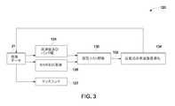
図3は、ディスプレイ122により表示された超音波画像データ121の軸方向/横方向空間分解能、信号対雑音比及び透過因子を推定することによって送信波形設定(周波数及びバンド幅)を調整する例示的な自動画像最適化システム120の概要図である。軸方向/横方向空間分解能及び信号対雑音比に影響を及ぼす因子には、参照番号124で表した周波数及びバンド幅が含まれる。ここに図示したように、プロセッサ28(図1)で作成された画像に基づいて暫定の周波数及びバンド幅124並びに信号対雑音比126が推定される。推定した周波数及びバンド幅並びに信号対雑音比は、画像の軸方向及び横方向分解能並びに信号対雑音比を改善させた出力像132になるようにアパーチャサイズを調整する参照番号130で表した画質コスト関数に供給される。画質計測量が最大化に至らない場合は、参照番号134で表したようにフィードバックループ内で周波数最適化を反復して実行する。具体的なある実施形態では、信号とノイズの両方を包含した画像フレームが受け取られる。ノイズだけを包含したゼロ送信振幅から取得されるノイズフレームも受け取られる。次いで信号対雑音比126が算出されて画質コスト関数130に供給される。
FIG. 3 is an example of adjusting transmit waveform settings (frequency and bandwidth) by estimating axial / lateral spatial resolution, signal-to-noise ratio, and transmission factor of ultrasound image data 121 displayed by display 122. 1 is a schematic diagram of a simple automatic
したがって、上述した超音波画像最適化のためのシステム及び方法の様々な実施形態によって、画質を最適化させるための好都合でありかつ効率がよい手段を達成するための方法が得られる。さらに本技法を自動化すれば操作者依存性が排除される。さらに本システム及び技法により費用対効果のよい手段が可能となる。 Thus, the various embodiments of the ultrasound image optimization system and method described above provide a method for achieving a convenient and efficient means for optimizing image quality. Furthermore, if this technique is automated, operator dependence is eliminated. In addition, the present system and technique allows for cost effective means.
特定の任意の実施形態に従って上述した目的または利点の必ずしもすべてを達成できるわけではないことを理解すべきである。したがって例えば、本明細書において教示または示唆されるような別の目的または利点を必ずしも達成することなく、本明細書における教示に従った1つの利点または利点の組を達成または最適化するような方式で本明細書に記載したシステム及び技法を具現化または実施できることは当業者であれば理解されよう。 It should be understood that not all of the objectives or advantages described above can be achieved in accordance with any particular embodiment. Thus, for example, a scheme that achieves or optimizes one set of advantages or advantages in accordance with the teachings herein without necessarily achieving another objective or advantage as taught or suggested herein. Those skilled in the art will appreciate that the systems and techniques described herein can be implemented or implemented.
さらに当業者であれば様々な実施形態からの様々な特徴が相互に置き換え可能であることを理解されよう。例えば、ある実施形態に関する手持ち式超音波トランスジューサの使用は、別の実施形態に関連して記載したフレームレートを調整するように構成された画質コスト関数と共に使用するように適合させることが可能である。同様に当業者は、記載した様々な特徴、並びに各特徴に関する別の周知の等価形態を混合しマッチングさせ、この開示の原理に従った追加的なシステム及び技法を構築することが可能である。 Moreover, those skilled in the art will appreciate that various features from the various embodiments can be interchanged. For example, the use of a handheld ultrasound transducer for one embodiment can be adapted for use with an image quality cost function configured to adjust the frame rate described in connection with another embodiment. . Similarly, those skilled in the art can mix and match the various described features, as well as other known equivalent forms for each feature, to build additional systems and techniques in accordance with the principles of this disclosure.
本発明について限られた数の実施形態のみに関連して詳細に記載してきたが、本発明が開示したこうした実施形態に限定されないことは容易に理解できよう。それどころか本発明は、ここまでに記載していないが本発明の精神及び趣旨に相応するような任意の数の変形形態、修正形態、置換形態、等価形態の機構を組み込むように修正することが可能である。さらに、本発明に関して様々な実施形態を記載しているが、本発明の態様は記載した実施形態のうちの一部のみを含むこともあり得ることを理解すべきである。したがって、本発明は上述の記述によって限定されるものと理解すべきではなく、添付の特許請求の範囲の趣旨によってのみ限定されるものと理解すべきである。 While the invention has been described in detail in connection with only a limited number of embodiments, it will be readily understood that the invention is not limited to such disclosed embodiments. On the contrary, the present invention can be modified to incorporate any number of variations, modifications, substitutions, equivalents of mechanisms not heretofore described, but commensurate with the spirit and spirit of the present invention. It is. Furthermore, while various embodiments have been described with respect to the present invention, it is to be understood that aspects of the present invention may include only some of the described embodiments. Accordingly, the invention should not be understood as limited by the foregoing description, but should be construed as limited only by the spirit of the appended claims.
10 対象の超音波撮像のためのシステム
14 対象
16 超音波トランスジューサ
18 第1の超音波信号
22 第1組の反射超音波信号
24 第1組の電気信号
28 プロセッサ
29 処理済み画像データ
32 第1の画像
34 表示モニタ
36 画質コスト関数
45 第2組の反射超音波信号
46 第2組のパラメータを有する第2組の超音波信号
47 第2組の電気信号
49 画像データ
52 得られた第2の画像
80 対象の超音波撮像における画像最適化のための方法
82 対象内に第1の超音波信号を送信する工程
84 対象からの第1の超音波信号の反射を表した第1組の電気信号を受信する工程
86 第1の画像になるように第1組の電気信号を処理する工程
88 第1の画像に関する画質コスト関数を評価して第1の画質計測量を生成する工程
90 第1の画質因子に基づいて第2組の信号パラメータを予測する工程
92 対象内に第2の超音波信号を送信する工程
94 対象からの第2の超音波信号の反射を表した第2組の電気信号を受信する工程
96 第2の画像になるように第2組の電気信号を処理する工程
98 第2の画像に関する画質コスト関数を評価して第2の画質計測量を生成する工程
100 最大化画質計測量に到達したか否かを判定するために第1の画質計測量と第2の画質計測量を比較する工程
102 最大化画質計測量を生成させた複数の信号パラメータを最適なパラメータとして割り当てる工程
104 最適なパラメータを有する超音波信号を用いて対象を撮像する工程
106 最適なパラメータを有する超音波信号に基づいて対象から得られた画像を表示する工程
120 例示的な自動画像最適化システム
121 超音波画像データ
122 ディスプレイ
124 周波数及びバンド幅
126 信号対雑音比
130 画質コスト関数
132 出力像
134 反復式の周波数最適化
DESCRIPTION OF SYMBOLS 10 System for ultrasonic imaging of object 14 Object 16 Ultrasonic transducer 18 First ultrasonic signal 22 First set of reflected ultrasonic signals 24 First set of electrical signals 28 Processor 29 Processed image data 32 First Image 34 Display monitor 36 Image quality cost function 45 Second set of reflected ultrasound signals 46 Second set of ultrasound signals having second set of parameters 47 Second set of electrical signals 49 Image data 52 Obtained second image 80 Method for Image Optimization in Ultrasound Imaging of an Object 82 Transmitting a First Ultrasound Signal into the Object 84 A First Set of Electrical Signals Representing the Reflection of the First Ultrasound Signal from the Object Receiving 86 processing the first set of electrical signals to be a first image 88 generating an image quality measure by evaluating an image quality cost function for the first image 90 predicting a second set of signal parameters based on the first image quality factor 92 transmitting a second ultrasound signal within the object 94 representing the reflection of the second ultrasound signal from the object Receiving the second set of electrical signals 96 processing the second set of electrical signals to form a second image 98 generating a second image quality measurement quantity by evaluating an image quality cost function for the second image Step 100: comparing the first image quality measurement amount with the second image quality measurement amount to determine whether or not the maximized image quality measurement amount has been reached 102. A plurality of signal parameters that have generated the maximized image quality measurement amount Assigning as an
Claims (10)
対象内に第1の複数の信号パラメータを有する第1の超音波信号を送信する工程(82)と、
対象からの第1の超音波信号の反射を表した第1組の電気信号を受信する工程(84)と、
画質因子の組を有する第1の画像になるように第1組の電気信号を処理する工程(86)と、
第1の画像に関する画質コスト関数を評価して第1の画質計測量を生成する工程(88)と、
第1の画質計測量に基づいて第2の複数の信号パラメータを決定する工程(90)と、
対象内に第2の複数の信号パラメータを有する第2の超音波信号を送信する工程(92)と、
対象からの第2の超音波信号の反射を表した第2組の電気信号を受信する工程(94)と、
前記画質因子の組を有する第2の画像になるように第2組の電気信号を処理する工程(96)と、
第2の画像に関する画質コスト関数を評価して第2の画質計測量を生成する工程(98)と、
最大化画質計測量に到達したか否かを判定するために第1の画質計測量と第2の画質計測量を比較する工程(100)と、
最大化画質計測量を生成させた複数の信号パラメータを最適なパラメータとして割り当てる工程(102)と、
最適なパラメータを有する超音波信号を用いて対象を撮像する工程(104)と、
最適なパラメータを有する超音波信号に基づいて対象から得られた画像を表示する工程(106)と、
を含み、
第2の画質計測量を生成する前記工程(98)が、複数の画質因子の重み付け総和と定義される画質コスト関数を計算する工程を含む、
自動画像最適化方法(80)。 A method (80) for automatic image optimization in ultrasound imaging of a subject (14) comprising:
Transmitting a first ultrasound signal having a first plurality of signal parameters within the object (82);
Receiving (84) a first set of electrical signals representing reflections of a first ultrasound signal from a subject;
Processing (86) the first set of electrical signals to become a first image having a set of image quality factors ;
Evaluating the image quality cost function for the first image to generate a first image quality measurement quantity (88);
Determining a second plurality of signal parameters based on the first image quality measurement quantity;
Transmitting a second ultrasound signal having a second plurality of signal parameters within the object (92);
Receiving (94) a second set of electrical signals representative of the reflection of the second ultrasound signal from the object;
Processing (96) a second set of electrical signals to become a second image having the set of image quality factors ;
Evaluating the image quality cost function for the second image to generate a second image quality measurement quantity (98);
Comparing (100) the first image quality measurement amount and the second image quality measurement amount to determine whether or not the maximized image quality measurement amount has been reached;
Assigning a plurality of signal parameters that have generated the maximized image quality measurement amount as optimum parameters (102);
Imaging an object using an ultrasound signal having optimal parameters (104);
Displaying an image obtained from the object based on an ultrasound signal having optimal parameters (106);
Only including,
Said step (98) of generating a second image quality measurement comprises calculating an image quality cost function defined as a weighted sum of a plurality of image quality factors;
Automatic image optimization method (80).
対象(14)と音響的に結合された超音波トランスジューサ(16)であって、
第1の複数の信号パラメータと第2の複数の信号パラメータをそれぞれ含む第1の超音波信号(18)と第2の超音波信号(46)を対象(14)内に送信すること、
対象からの第1組の反射超音波信号(22)と第2組の反射信号(45)を対応する第1組の電気信号(24)と第2組の電気信号(47)に変換すること、
を行うように構成され超音波トランスジューサ(16)と、
前記超音波トランスジューサ(16)に結合されたプロセッサ(28)であって、
第1組の電気信号(24)と第2組の電気信号(47)をある画質因子の組を有する第1の画像(32)と第2の画像(52)になるように処理すること、
第1の画質計測量及び第2の画質計測量を生成するように第1の画像(32)及び第2の画像(52)に関する画質コスト関数(36)を評価すること、
第1の画質計測量に基づいて第2の複数の信号パラメータを決定すること、
最大化画質計測量に到達したか否かを判定するために第1の画質計測量と第2の画質計測量を比較すること、
最大化画質計測量を生成させた複数のパラメータを最適なパラメータとして割り当てること、
最適なパラメータを有する超音波信号を用いて対象を撮像すること、
を行うように構成されたプロセッサ(28)と、
最適なパラメータを有する超音波信号からの対象の撮像に基づいて対象(14)から得られた画像を表示するように構成された表示モニタ(34)と、
を備え、
前記画質コスト関数(36)が、複数の画質因子の重み付け総和と定義される、
システム(10)。 A system (10) for image optimization in ultrasound imaging of an object (14) comprising:
An ultrasonic transducer (16) acoustically coupled to a subject (14),
Transmitting a first ultrasound signal (18) and a second ultrasound signal (46), each including a first plurality of signal parameters and a second plurality of signal parameters, into the object (14);
Converting the first set of reflected ultrasound signals (22) and the second set of reflected signals (45) from the subject into corresponding first set of electrical signals (24) and second set of electrical signals (47); ,
An ultrasonic transducer (16) configured to perform:
A processor (28) coupled to the ultrasonic transducer (16), comprising:
Processing the first set of electrical signals (24) and the second set of electrical signals (47) into a first image (32) and a second image (52) having a set of image quality factors ;
Evaluating an image quality cost function (36) for the first image (32) and the second image (52) to generate a first image quality measure and a second image quality measure;
Determining a second plurality of signal parameters based on the first image quality measurement quantity;
Comparing the first image quality measurement amount and the second image quality measurement amount to determine whether or not the maximized image quality measurement amount has been reached;
Assigning the multiple parameters that generated the maximized image quality measurement quantity as optimal parameters,
Imaging an object using an ultrasound signal having optimal parameters;
A processor (28) configured to perform:
A display monitor (34) configured to display an image obtained from the object (14) based on imaging of the object from an ultrasound signal having optimal parameters;
Equipped with a,
The image quality cost function (36) is defined as a weighted sum of a plurality of image quality factors.
System (10).
Applications Claiming Priority (2)
| Application Number | Priority Date | Filing Date | Title |
|---|---|---|---|
| US12/471,732 US8235905B2 (en) | 2009-05-26 | 2009-05-26 | System and method for automatic ultrasound image optimization |
| US12/471,732 | 2009-05-26 |
Publications (3)
| Publication Number | Publication Date |
|---|---|
| JP2010274111A JP2010274111A (en) | 2010-12-09 |
| JP2010274111A5 JP2010274111A5 (en) | 2013-06-27 |
| JP5508934B2 true JP5508934B2 (en) | 2014-06-04 |
Family
ID=43221014
Family Applications (1)
| Application Number | Title | Priority Date | Filing Date |
|---|---|---|---|
| JP2010113831A Active JP5508934B2 (en) | 2009-05-26 | 2010-05-18 | System and method for automatic ultrasound image optimization |
Country Status (3)
| Country | Link |
|---|---|
| US (1) | US8235905B2 (en) |
| JP (1) | JP5508934B2 (en) |
| CN (1) | CN101897600B (en) |
Families Citing this family (23)
| Publication number | Priority date | Publication date | Assignee | Title |
|---|---|---|---|---|
| US20120136248A1 (en) * | 2010-11-25 | 2012-05-31 | Toshiba Medical Systems Corporation | Ultrasound diagnosis apparatus, image generating method, and image processing apparatus |
| US8724878B2 (en) | 2012-01-12 | 2014-05-13 | General Electric Company | Ultrasound image segmentation |
| WO2013154079A1 (en) * | 2012-04-11 | 2013-10-17 | 株式会社東芝 | Ultrasound diagnostic device |
| CN102800072B (en) * | 2012-06-20 | 2015-07-29 | 无锡祥生医学影像有限责任公司 | Diasonograph scan image quality optimization disposal route and device thereof |
| US9918700B2 (en) | 2013-02-01 | 2018-03-20 | Siemens Medical Solutions Usa, Inc. | Tuning ultrasound acquisition parameters |
| KR101980537B1 (en) | 2013-07-11 | 2019-05-22 | 삼성전자주식회사 | imaging processing unit, ultrasonic imaging apparatus and image processing method |
| US9224213B2 (en) | 2013-12-31 | 2015-12-29 | Facebook, Inc. | Systems and methods for context based image compression |
| CN106470612B (en) * | 2014-06-30 | 2020-03-24 | 皇家飞利浦有限公司 | Translating an ultrasound array in response to anatomical characterization |
| US9918701B2 (en) | 2014-09-03 | 2018-03-20 | Contextvision Ab | Methods and systems for automatic control of subjective image quality in imaging of objects |
| US9743911B2 (en) | 2014-09-03 | 2017-08-29 | Contextvision Ab | Methods and systems for automatic control of subjective image quality in imaging of objects |
| KR102582540B1 (en) * | 2015-06-16 | 2023-09-25 | 삼성메디슨 주식회사 | ULTRASOUND APPARATUS AND operating method for the same |
| US11096671B2 (en) * | 2015-09-10 | 2021-08-24 | Siemens Medical Solutions Usa, Inc. | Sparkle artifact detection in ultrasound color flow |
| CN105496459B (en) * | 2016-01-15 | 2018-09-21 | 飞依诺科技(苏州)有限公司 | Automatic adjustment method and system for ultrasonic imaging equipment |
| WO2018130370A1 (en) | 2017-01-11 | 2018-07-19 | Contextvision Ab | Methods and systems for automatic control of subjective image quality in imaging of objects |
| US10786226B2 (en) | 2017-02-09 | 2020-09-29 | Clarius Mobile Health Corp. | Ultrasound systems and methods for optimizing multiple imaging parameters using a single user interface control |
| US10628932B2 (en) * | 2017-10-27 | 2020-04-21 | Butterfly Network, Inc. | Quality indicators for collection of and automated measurement on ultrasound images |
| US20200297318A1 (en) * | 2017-11-02 | 2020-09-24 | Koninklijke Philips N.V. | Intelligent ultrasound system for detecting image artefacts |
| US11602332B2 (en) * | 2019-10-29 | 2023-03-14 | GE Precision Healthcare LLC | Methods and systems for multi-mode ultrasound imaging |
| US20210169455A1 (en) * | 2019-12-04 | 2021-06-10 | GE Precision Healthcare LLC | System and methods for joint scan parameter selection |
| US11308609B2 (en) * | 2019-12-04 | 2022-04-19 | GE Precision Healthcare LLC | System and methods for sequential scan parameter selection |
| US11488298B2 (en) * | 2019-12-20 | 2022-11-01 | GE Precision Healthcare LLC | System and methods for ultrasound image quality determination |
| EP3923293A1 (en) * | 2020-06-09 | 2021-12-15 | Koninklijke Philips N.V. | System and method for analysis of medical image data based on an interaction of quality metrics |
| EP4098199A1 (en) * | 2021-06-01 | 2022-12-07 | Koninklijke Philips N.V. | Apparatus for medical image analysis |
Family Cites Families (9)
| Publication number | Priority date | Publication date | Assignee | Title |
|---|---|---|---|---|
| EP0533976B1 (en) | 1991-09-26 | 1996-05-15 | Dornier Medizintechnik Gmbh | Automatic optimization of the image uniformity of an ultrasound imaging system |
| US6120446A (en) | 1998-12-17 | 2000-09-19 | Acuson Corporation | Diagnostic medical ultrasonic imaging system and method with adaptive gain |
| US6699189B1 (en) | 2000-12-26 | 2004-03-02 | University Of Rochester | Ultrasound distortion compensation using blind system identification |
| JP2003235839A (en) * | 2002-02-18 | 2003-08-26 | Matsushita Electric Ind Co Ltd | Ultrasonic diagnostic system |
| US6743174B2 (en) | 2002-04-01 | 2004-06-01 | Koninklijke Philips Electronics N.V. | Ultrasonic diagnostic imaging system with automatically controlled contrast and brightness |
| US6733454B1 (en) | 2003-02-26 | 2004-05-11 | Siemens Medical Solutions Usa, Inc. | Automatic optimization methods and systems for doppler ultrasound imaging |
| CN1190753C (en) * | 2003-02-28 | 2005-02-23 | 清华大学 | Ultrasonic dynamic receiving apodization method based on delta-sigma transformation |
| US7578792B2 (en) * | 2003-07-21 | 2009-08-25 | Siemens Medical Solutions Usa, Inc. | Automatic optimization in spectral Doppler ultrasound imaging |
| EP1965705A2 (en) | 2005-12-19 | 2008-09-10 | Koninklijke Philips Electronics N.V. | Automatic ultrasound scanning initiated by protocol stage |
-
2009
- 2009-05-26 US US12/471,732 patent/US8235905B2/en not_active Expired - Fee Related
-
2010
- 2010-05-18 JP JP2010113831A patent/JP5508934B2/en active Active
- 2010-05-26 CN CN201010197260.4A patent/CN101897600B/en not_active Expired - Fee Related
Also Published As
| Publication number | Publication date |
|---|---|
| US20100305441A1 (en) | 2010-12-02 |
| US8235905B2 (en) | 2012-08-07 |
| JP2010274111A (en) | 2010-12-09 |
| CN101897600A (en) | 2010-12-01 |
| CN101897600B (en) | 2014-04-02 |
Similar Documents
| Publication | Publication Date | Title |
|---|---|---|
| JP5508934B2 (en) | System and method for automatic ultrasound image optimization | |
| US6142942A (en) | Ultrasound imaging system and method employing an adaptive filter | |
| US6120446A (en) | Diagnostic medical ultrasonic imaging system and method with adaptive gain | |
| US8235900B2 (en) | Method and apparatus for an automatic ultrasound imaging system | |
| JP5248961B2 (en) | Ultrasonic diagnostic equipment | |
| KR20070092407A (en) | Image processing system and method | |
| JP2006043457A (en) | Method and system for controlling ultrasonic system | |
| CN105559828B (en) | Blood flow imaging method and system | |
| US20110054317A1 (en) | Tracking and optimizing gain and contrast in real-time for ultrasound imaging | |
| JP2015213575A (en) | Ultrasonic diagnostic device and ultrasonic imaging program | |
| JP7370903B2 (en) | Ultrasonic diagnostic equipment, learning equipment, image processing methods and programs | |
| CN113491536A (en) | Ultrasonic imaging apparatus and image processing apparatus | |
| JP2016002208A (en) | Ultrasonic diagnostic equipment | |
| JP4808373B2 (en) | Method and apparatus for applications related to B-mode image banding suppression | |
| JP6169361B2 (en) | Ultrasonic diagnostic apparatus and brightness correction method | |
| JP5380114B2 (en) | Ultrasonic diagnostic apparatus and ultrasonic diagnostic apparatus control method | |
| JP6396590B2 (en) | Method and system for adjusting image gain | |
| JP5269626B2 (en) | Ultrasonic diagnostic equipment | |
| Guenther et al. | Robust finite impulse response beamforming applied to medical ultrasound | |
| JP2005177338A (en) | Ultrasonic diagnostic instrument | |
| JP7280713B2 (en) | ultrasound diagnostic equipment | |
| US20230301625A1 (en) | Ultrasonic imaging method, ultrasonic imaging apparatus and storage medium | |
| JP2024000892A (en) | Ultrasonic diagnostic device | |
| WO2011001867A1 (en) | Ultrasonic wave diagnosing device and sound speed correction method | |
| JP2023146587A (en) | Ultrasonic diagnostic apparatus |
Legal Events
| Date | Code | Title | Description |
|---|---|---|---|
| A521 | Request for written amendment filed |
Free format text: JAPANESE INTERMEDIATE CODE: A523 Effective date: 20130513 |
|
| A621 | Written request for application examination |
Free format text: JAPANESE INTERMEDIATE CODE: A621 Effective date: 20130513 |
|
| TRDD | Decision of grant or rejection written | ||
| A977 | Report on retrieval |
Free format text: JAPANESE INTERMEDIATE CODE: A971007 Effective date: 20140228 |
|
| A01 | Written decision to grant a patent or to grant a registration (utility model) |
Free format text: JAPANESE INTERMEDIATE CODE: A01 Effective date: 20140304 |
|
| A61 | First payment of annual fees (during grant procedure) |
Free format text: JAPANESE INTERMEDIATE CODE: A61 Effective date: 20140324 |
|
| R150 | Certificate of patent or registration of utility model |
Ref document number: 5508934 Country of ref document: JP Free format text: JAPANESE INTERMEDIATE CODE: R150 |
|
| R250 | Receipt of annual fees |
Free format text: JAPANESE INTERMEDIATE CODE: R250 |
|
| R250 | Receipt of annual fees |
Free format text: JAPANESE INTERMEDIATE CODE: R250 |
|
| R250 | Receipt of annual fees |
Free format text: JAPANESE INTERMEDIATE CODE: R250 |
|
| R250 | Receipt of annual fees |
Free format text: JAPANESE INTERMEDIATE CODE: R250 |
|
| R250 | Receipt of annual fees |
Free format text: JAPANESE INTERMEDIATE CODE: R250 |
|
| R250 | Receipt of annual fees |
Free format text: JAPANESE INTERMEDIATE CODE: R250 |
|
| R250 | Receipt of annual fees |
Free format text: JAPANESE INTERMEDIATE CODE: R250 |
|
| R250 | Receipt of annual fees |
Free format text: JAPANESE INTERMEDIATE CODE: R250 |