JP5501743B2 - Dust-proof structure of movable cover support in cutting machine - Google Patents
Dust-proof structure of movable cover support in cutting machine Download PDFInfo
- Publication number
- JP5501743B2 JP5501743B2 JP2009271534A JP2009271534A JP5501743B2 JP 5501743 B2 JP5501743 B2 JP 5501743B2 JP 2009271534 A JP2009271534 A JP 2009271534A JP 2009271534 A JP2009271534 A JP 2009271534A JP 5501743 B2 JP5501743 B2 JP 5501743B2
- Authority
- JP
- Japan
- Prior art keywords
- dust
- support ring
- elastic member
- movable cover
- main body
- Prior art date
- Legal status (The legal status is an assumption and is not a legal conclusion. Google has not performed a legal analysis and makes no representation as to the accuracy of the status listed.)
- Active
Links
- 238000005520 cutting process Methods 0.000 title claims description 125
- 230000002093 peripheral effect Effects 0.000 claims description 51
- 239000000428 dust Substances 0.000 claims description 46
- 239000000463 material Substances 0.000 claims description 16
- 239000011347 resin Substances 0.000 claims description 5
- 229920005989 resin Polymers 0.000 claims description 5
- 230000033001 locomotion Effects 0.000 claims description 2
- 238000006073 displacement reaction Methods 0.000 description 12
- 230000001105 regulatory effect Effects 0.000 description 7
- 239000000843 powder Substances 0.000 description 3
- 229930182556 Polyacetal Natural products 0.000 description 2
- 206010044565 Tremor Diseases 0.000 description 2
- 238000000034 method Methods 0.000 description 2
- 238000012986 modification Methods 0.000 description 2
- 230000004048 modification Effects 0.000 description 2
- 229920006324 polyoxymethylene Polymers 0.000 description 2
- 238000005452 bending Methods 0.000 description 1
- 230000000903 blocking effect Effects 0.000 description 1
- 238000007664 blowing Methods 0.000 description 1
- 238000006243 chemical reaction Methods 0.000 description 1
- 238000007796 conventional method Methods 0.000 description 1
- 230000000694 effects Effects 0.000 description 1
- 230000009545 invasion Effects 0.000 description 1
- 239000002184 metal Substances 0.000 description 1
- 230000035515 penetration Effects 0.000 description 1
- 230000002265 prevention Effects 0.000 description 1
- 238000007789 sealing Methods 0.000 description 1
- 238000005507 spraying Methods 0.000 description 1
Images


Classifications
-
- B—PERFORMING OPERATIONS; TRANSPORTING
- B23—MACHINE TOOLS; METAL-WORKING NOT OTHERWISE PROVIDED FOR
- B23D—PLANING; SLOTTING; SHEARING; BROACHING; SAWING; FILING; SCRAPING; LIKE OPERATIONS FOR WORKING METAL BY REMOVING MATERIAL, NOT OTHERWISE PROVIDED FOR
- B23D47/00—Sawing machines or sawing devices working with circular saw blades, characterised only by constructional features of particular parts
-
- B—PERFORMING OPERATIONS; TRANSPORTING
- B25—HAND TOOLS; PORTABLE POWER-DRIVEN TOOLS; MANIPULATORS
- B25F—COMBINATION OR MULTI-PURPOSE TOOLS NOT OTHERWISE PROVIDED FOR; DETAILS OR COMPONENTS OF PORTABLE POWER-DRIVEN TOOLS NOT PARTICULARLY RELATED TO THE OPERATIONS PERFORMED AND NOT OTHERWISE PROVIDED FOR
- B25F5/00—Details or components of portable power-driven tools not particularly related to the operations performed and not otherwise provided for
- B25F5/02—Construction of casings, bodies or handles
-
- B—PERFORMING OPERATIONS; TRANSPORTING
- B27—WORKING OR PRESERVING WOOD OR SIMILAR MATERIAL; NAILING OR STAPLING MACHINES IN GENERAL
- B27B—SAWS FOR WOOD OR SIMILAR MATERIAL; COMPONENTS OR ACCESSORIES THEREFOR
- B27B9/00—Portable power-driven circular saws for manual operation
-
- B—PERFORMING OPERATIONS; TRANSPORTING
- B27—WORKING OR PRESERVING WOOD OR SIMILAR MATERIAL; NAILING OR STAPLING MACHINES IN GENERAL
- B27G—ACCESSORY MACHINES OR APPARATUS FOR WORKING WOOD OR SIMILAR MATERIALS; TOOLS FOR WORKING WOOD OR SIMILAR MATERIALS; SAFETY DEVICES FOR WOOD WORKING MACHINES OR TOOLS
- B27G19/00—Safety guards or devices specially adapted for wood saws; Auxiliary devices facilitating proper operation of wood saws
- B27G19/02—Safety guards or devices specially adapted for wood saws; Auxiliary devices facilitating proper operation of wood saws for circular saws
- B27G19/04—Safety guards or devices specially adapted for wood saws; Auxiliary devices facilitating proper operation of wood saws for circular saws for manually-operated power-driven circular saws
Description
この発明は、切断加工や研削加工により発生する粉塵に対する高い防塵性が要求される場合に好適な切断機における可動カバー支持部の防塵構造に関する。 The present invention relates to a dust-proof structure for a movable cover support portion in a cutting machine suitable for a case where high dust resistance against dust generated by cutting or grinding is required.
使用者が手に持って切断材上を移動させて切断加工を行う携帯形の切断機は、切断材上に乗せ掛けるベースの上面側に切断機本体を支持した構成を備えている。切断機本体は、電動モータにより回転する円形の切断刃を備えており、この切断刃の下部側がベースの下面側に突き出されて切断材に切り込まれる。切断刃の上部側は本体ケースに覆われ、ベース下面側に突き出された下部側は可動カバーで覆われるようになっている。可動カバーは、本体ケースに回動可能に支持されて、切断刃の切断材に対する切り込み量に応じて開閉されており、閉じ側にばね付勢されている。
この可動カバーは、ベース上面側において本体ケースの円筒形状を有するベアリングボックスの外周側に回動可能に支持されている。ベアリングボックスには、切断刃を取り付けたスピンドルを回転自在に支持するベアリングが取り付けられている。
ベアリングボックスの周辺を含む本体ケース内には、切断加工により切断部位から吹き上げられる切断粉が飛散する。一方、可動カバーの回動支持部は、そのスムーズな開閉動作を確保する必要上、ベアリングボックスに対して径方向及び軸方向に適切なクリアランス(隙間)が設定されている。このため、可動カバーの回動支持部とベアリングボックスとの間の隙間に切断粉等の粉塵が侵入すると、可動カバーのスムーズな開閉動作に支障を来すおそれがある。従来、この粉塵対策として、例えば下記の特許文献に開示された技術が提供されている。この従来の技術は、スピンドル支持用のベアリングとは別に、ベアリングボックスの外周側に可動カバー支持用の第2のベアリングを取り付け、この第2のベアリングを介して可動カバーを回動可能に支持することにより上記のクリアランスをなくす一方、この第2のベアリングのシール部材をシールカバーで遮蔽してその防塵を行う構成となっていた。
2. Description of the Related Art A portable cutting machine that is held by a user and moves on a cutting material to perform cutting processing has a configuration in which a cutting machine body is supported on the upper surface side of a base that is placed on the cutting material. The main body of the cutting machine includes a circular cutting blade that is rotated by an electric motor, and the lower side of the cutting blade protrudes toward the lower surface side of the base and is cut into the cutting material. The upper side of the cutting blade is covered with the main body case, and the lower side protruding to the lower surface of the base is covered with a movable cover. The movable cover is rotatably supported by the main body case, is opened / closed according to the amount of cutting of the cutting blade with respect to the cutting material, and is biased to the closed side.
The movable cover is rotatably supported on the outer peripheral side of a bearing box having a cylindrical shape of the main body case on the base upper surface side. A bearing that rotatably supports a spindle with a cutting blade attached thereto is attached to the bearing box.
In the main body case including the periphery of the bearing box, cutting powder blown up from the cutting site by the cutting process is scattered. On the other hand, the rotation support portion of the movable cover has an appropriate clearance (gap) in the radial direction and the axial direction with respect to the bearing box in order to ensure a smooth opening / closing operation. For this reason, if dust such as cutting powder enters the gap between the rotation support portion of the movable cover and the bearing box, there is a risk of hindering the smooth opening and closing operation of the movable cover. Conventionally, as a countermeasure against this dust, for example, techniques disclosed in the following patent documents have been provided. In this conventional technique, a second bearing for supporting the movable cover is attached to the outer peripheral side of the bearing box separately from the bearing for supporting the spindle, and the movable cover is rotatably supported via the second bearing. Thus, the clearance is eliminated, and the seal member of the second bearing is shielded by a seal cover to prevent dust.
しかしながら、上記特許文献に開示された従来技術は、本体ケースにスピンドルを回転支持する第1のベアリングに加えて第2のベアリングを用いることにより可動カバーをベアリングボックスに回転支持する構成であるので、コスト高になる問題がある。このため、係る特別のベアリングを用いることなく可動カバーの回動支持部について一層確実な防塵対策を施すことができる技術が望まれていた。
そこで、本発明は、切断刃のベース下面側の刃先を開閉する可動カバーの本体ケースに対する回動支持部について、従来のような特別のベアリングを用いることなく可動カバーをスムーズに開閉可能に支持しつつその防塵性をより一層高めることを目的とする。
However, the prior art disclosed in the above-mentioned patent document is a configuration in which the movable cover is rotationally supported on the bearing box by using the second bearing in addition to the first bearing that rotationally supports the spindle in the main body case. There is a problem of high costs. For this reason, the technique which can take a more reliable dust-proof measure about the rotation support part of a movable cover, without using the special bearing which concerns is desired.
Therefore, the present invention supports a movable cover that can be opened and closed smoothly without using a special bearing as in the conventional case, with respect to the rotation support portion for the main body case of the movable cover that opens and closes the cutting edge on the base lower surface side of the cutting blade. However, it aims at further improving the dustproof property.
上記の課題は、以下の各発明により解決される。
第1の発明は、切断材の上面に当接させるベースと、該ベースの上面側に支持された切断機本体を備え、該切断機本体は、本体ケースと、電動モータにより回転する円形の切断刃を有し、該切断刃の上部が前記本体ケースに覆われ、該切断刃の下部が前記ベースの下面側に突き出され、該突き出し部分の刃先が可動カバーにより開閉可能に覆われた切断機における前記可動カバーの前記本体ケースに対する回転支持部の防塵構造であって、切断刃は、前記本体ケースのベアリングボックスに収容したベアリングにより回転支持されたスピンドルに取り付けられており、可動カバーは円筒形の支持円環部を備え、該支持円環部を前記ベアリングボックスの外周側に回転可能に支持して前記刃先を開閉可能に回転支持されており、可動カバーの支持円環部は、前記ベアリングボックス部に設けた軸方向規制部により当該軸方向両側への変位が規制されており、支持円環部の軸方向端面と前記軸方向規制部との間に円環形状の弾性部材を押圧状態で介装して、前記切断刃側から前記支持円環部の内周側に至る粉塵の侵入経路を遮断する構成とした防塵構造である。
第1の発明によれば、可動カバーの支持円環部(可動カバー支持部)とベアリングボックスの軸方向規制部との間に円環形状の弾性部材が押圧状態で介装されて、切断刃側から支持円環部の内周側に至る粉塵の侵入経路が遮断されているので、弾性部材よりも内周側に粉塵が侵入することが防止される。このことから、弾性部材で遮断された支持円環部の内周側について、支持円環部とベアリングボックスとの間に適度なクリアランスを設定して当該可動カバーのスムーズな開閉動作を確保しつつ、高い防塵性を持たせることができるので、従来のようにベアリングボックスに対する可動カバーの支持円環部のクリアランスをなくすために別途特別のベアリング(第2のベアリング)を用いる必要はなくなる。このため、従来の特別のベアリングを省略することによりコスト低減を図りつつ可動カバーのスムーズな開閉動作とその支持部の高い防塵性を確保することができる。
また、支持円環部と軸方向規制部との間に弾性部材が押圧状態で介在されるので、当該支持円環部の軸方向のがたつきを抑制することができ、ひいては可動カバーの開閉方向に直交する方向のがたつき(開閉方向左右への振れ)を抑制することができる。
第2の発明は、弾性部材は、縮径方向の付勢力に抗して拡径方向に変位可能であり、支持円環部と軸方向規制部との間に弾性部材の少なくとも一部を収容するための凹部を設け、軸方向規制部の押圧により弾性部材を拡径方向に変位させる方向に傾斜する傾斜面を軸方向規制部と支持円環部と弾性部材のいずれか一つに設けた防塵構造である。
第2の発明によれば、弾性部材の付勢力が可動カバーのスムーズな開閉動作について過度な回転抵抗(開閉抵抗)となることを防止することができる。
第3の発明は、第1又は第2の発明において、弾性部材は、樹脂を素材とする防塵構造である。
第3の発明によれば、弾性部材として金属製ではなく、例えば摺動性が高く摩擦係数の小さな高強度樹脂(ポリアセタール等)を素材として用いることにより、当該弾性部材を押圧することにより発生する摩擦によって可動カバーの開閉抵抗が増大することを抑制することができ、ひいては当該可動カバーのスムーズな開閉動作を確保することができる。
第4の発明は、第2の発明において、弾性部材の傾斜面に対する押圧面を平坦面に形成した防塵構造である。
第4の発明によれば、弾性部材を確実に拡径方向に押し広げて粉塵侵入経路のシール性を確保しつつ、軸方向規制部に押し付けたことによる摺動抵抗(回転抵抗)を極力小さくして可動カバーのスムーズな開閉動作を確保することができる。
第5の発明は、第1〜第4の何れか一つの発明において、弾性部材とこの弾性部材が押圧される軸方向規制部との間にワッシャを介在させた防塵構造である。
第5の発明によれば、軸方向規制部として規格品である止め輪を用いる場合に、より大径の弾性部材を任意サイズに加工できるワッシャを介して確実に押圧させることができ、この点で利用できる弾性部材のサイズについて選択の自由度が高まる。
第6の発明は、第1〜第5の何れか一つの発明において、弾性部材の軸方向規制部に対する押圧面を平坦面に形成して面当たりさせる構成とした防塵構造である。
第6の発明によれば、によれば、弾性部材の軸方向規制部材に対する押圧面積(シール面積)を大きくして、防塵性能を一層高めることができる。
Said subject is solved by each following invention.
1st invention is equipped with the base contact | abutted on the upper surface of a cutting material, and the cutting machine main body supported by the upper surface side of this base, and this cutting machine main body is circular cutting | disconnection rotated by a main body case and an electric motor. A cutting machine having a blade, wherein the upper portion of the cutting blade is covered by the main body case, the lower portion of the cutting blade is protruded to the lower surface side of the base, and the blade edge of the protruding portion is covered by a movable cover In the dust-proof structure of the rotation support portion of the movable cover with respect to the main body case, the cutting blade is attached to a spindle that is rotatably supported by a bearing housed in a bearing box of the main body case, and the movable cover is cylindrical. The support ring is rotatably supported on the outer peripheral side of the bearing box, and the blade edge is rotatably supported to be openable and closable. The annular part is restricted from being displaced in the axial direction by an axial restriction part provided in the bearing box part, and the annular part is interposed between the axial end surface of the support annular part and the axial restriction part. It is a dustproof structure in which an elastic member having a shape is interposed in a pressed state to block a dust intrusion path from the cutting blade side to the inner peripheral side of the support ring portion.
According to the first invention , an annular elastic member is interposed in a pressed state between the support ring portion (movable cover support portion) of the movable cover and the axial restriction portion of the bearing box, and the cutting blade Since the dust intrusion path from the side to the inner peripheral side of the support ring portion is blocked, the dust is prevented from entering the inner peripheral side of the elastic member. From this, while setting an appropriate clearance between the support ring part and the bearing box on the inner peripheral side of the support ring part blocked by the elastic member, while ensuring a smooth opening and closing operation of the movable cover Since high dust resistance can be provided, there is no need to use a special bearing (second bearing) separately in order to eliminate the clearance of the support ring of the movable cover with respect to the bearing box as in the prior art. For this reason, it is possible to secure a smooth opening / closing operation of the movable cover and a high dustproof property of the support portion while reducing the cost by omitting the conventional special bearing.
In addition, since the elastic member is interposed between the support ring portion and the axial direction restricting portion in a pressed state, it is possible to suppress the shakiness of the support ring portion in the axial direction, and thus open and close the movable cover. Shaking in the direction orthogonal to the direction (swing to the left and right in the opening and closing direction) can be suppressed.
In the second invention, the elastic member can be displaced in the diameter increasing direction against the urging force in the diameter reducing direction, and at least a part of the elastic member is accommodated between the support ring portion and the axial direction restricting portion. And an inclined surface that is inclined in a direction in which the elastic member is displaced in the diameter-expanding direction by pressing of the axial restricting portion is provided in any one of the axial restricting portion, the support annular portion, and the elastic member. Dust-proof structure.
According to the second invention , it is possible to prevent the biasing force of the elastic member from becoming an excessive rotational resistance (opening / closing resistance) for the smooth opening / closing operation of the movable cover.
According to a third invention, in the first or second invention, the elastic member is a dustproof structure made of resin.
According to the third invention , the elastic member is not made of metal, but is generated by pressing the elastic member by using, for example, a high-strength resin (polyacetal or the like) having a high slidability and a small friction coefficient as a material. An increase in opening / closing resistance of the movable cover due to friction can be suppressed, and as a result, a smooth opening / closing operation of the movable cover can be ensured.
4th invention is a dust-proof structure which formed the press surface with respect to the inclined surface of an elastic member in the 2nd invention in the flat surface.
According to the fourth aspect of the present invention , the sliding resistance (rotational resistance) caused by pressing against the axial direction restricting portion is made as small as possible while ensuring the sealing performance of the dust intrusion path by surely expanding the elastic member in the diameter expanding direction. Thus, a smooth opening / closing operation of the movable cover can be ensured.
A fifth invention is a dust-proof structure according to any one of the first to fourth inventions, wherein a washer is interposed between the elastic member and the axial restriction portion to which the elastic member is pressed.
According to the fifth invention , when the retaining ring which is a standard product is used as the axial direction restricting portion, the elastic member having a larger diameter can be surely pressed through the washer that can be processed into an arbitrary size. This increases the degree of freedom in selecting the size of the elastic member that can be used.
A sixth invention is a dustproof structure according to any one of the first to fifth inventions, wherein the pressing surface of the elastic member with respect to the axial direction restricting portion is formed as a flat surface and is brought into contact with the surface.
According to the sixth aspect of the invention, it is possible to further increase the dustproof performance by increasing the pressing area (seal area) of the elastic member against the axial restriction member.
また、上記の第1〜第6の発明(弾性部材シール構造)に代えて、以下に列挙する関連発明1〜5(ラビリンス構造)によっても同様の作用効果を得ることができる。
[関連発明1]切断材に乗せ掛けるベースと、該ベースの上面側に支持された切断機本体を備え、該切断機本体は、本体ケースと、電動モータにより回転する円形の切断刃を有し、該切断刃の上部が前記本体ケースに覆われ、該切断刃の下部が前記ベースの下面側に突き出され、該突き出し部分の刃先が可動カバーにより開閉可能に覆われた切断機における前記可動カバーの前記本体ケースに対する回転支持部の防塵構造であって、
前記切断刃は、前記本体ケースのベアリングボックスに収容したベアリングにより回転支持されたスピンドルに取り付けられており、
前記可動カバーは円筒形の支持円環部を備え、該支持円環部を前記ベアリングボックスの外周側に回転可能に支持して前記刃先を開閉可能に回転支持されており、
前記可動カバーの支持円環部は、前記ベアリングボックス部に設けた軸方向規制部により当該軸方向両側への変位が規制されており、
前記ベアリングボックスに、前記支持円環部の外周側に張り出す防塵壁部を設けて、前記切断刃側から前記支持円環部の内周側に至る粉塵の侵入経路を屈曲させた防塵構造。
この関連発明1に係る防塵構造によれば、支持円環部の内周側に至る粉塵の侵入経路が屈曲したいわゆるラビリンス構造を備えているので、可動カバーのスムーズな開閉動作を確保しつつその防塵性を高めることができる。
[関連発明2]関連発明1記載の防塵構造であって、前記ベアリングボックス側の防塵壁部を第1防塵壁部とし、該第1防塵壁部の外周側に張り出す第2防塵壁部を前記支持円環部に設けて、前記切断刃側から前記支持円環部の内周側に至る粉塵の侵入経路を屈曲させた防塵構造。
この関連発明2に係る防塵構造によれば、より防塵性能の高いラビリンス構造とすることができる。
[関連発明3]関連発明2記載の防塵構造であって、前記第2防塵壁部と前記ベアリングボックスとの間に円環形状の弾性部材を押圧状態で介在させた防塵構造。
この関連発明3に係る防塵構造によれば、ラビリンス構造と弾性部材の双方によって一層防塵性能を高めることができる。
Further, instead of the above first to sixth inventions (elastic member seal structure), similar effects can be obtained by
[Related Invention 1] A base on which a cutting material is placed, and a cutting machine main body supported on the upper surface of the base are provided. The main body of the cutting machine has a main body case and a circular cutting blade rotated by an electric motor. The movable cover in a cutting machine in which the upper part of the cutting blade is covered with the main body case, the lower part of the cutting blade is protruded to the lower surface side of the base, and the blade edge of the protruding part is covered with a movable cover so as to be opened and closed. A dust-proof structure of the rotation support portion with respect to the main body case,
The cutting blade is attached to a spindle that is rotatably supported by a bearing accommodated in a bearing box of the main body case,
The movable cover includes a cylindrical support ring part, and the support ring part is rotatably supported on the outer peripheral side of the bearing box so that the blade edge can be opened and closed.
The support ring part of the movable cover is restricted from being displaced in the axial direction by the axial restriction part provided in the bearing box part,
A dust-proof structure in which a dust-proof wall portion projecting to the outer peripheral side of the support ring portion is provided in the bearing box, and a dust intrusion path from the cutting blade side to the inner peripheral side of the support ring portion is bent.
The dust-proof structure according to this
[Related invention 2] The dust-proof structure according to
According to the dustproof structure according to this
[Related invention 3] The dustproof structure according to
According to the dustproof structure according to the related invention 3, the dustproof performance can be further enhanced by both the labyrinth structure and the elastic member.
[関連発明4]切断材に乗せ掛けるベースと、該ベースの上面側に支持された切断機本体を備え、該切断機本体は、本体ケースと、電動モータにより回転する円形の切断刃を有し、該切断刃の上部が前記本体ケースに覆われ、該切断刃の下部が前記ベースの下面側に突き出され、該突き出し部分の刃先が可動カバーにより開閉可能に覆われた切断機における前記可動カバーの前記本体ケースに対する回転支持部の防塵構造であって、
前記切断刃は、前記本体ケースのベアリングボックスに収容したベアリングにより回転支持されたスピンドルに取り付けられており、
前記可動カバーは円筒形の支持円環部を備え、該支持円環部を前記ベアリングボックスの外周側に回転可能に支持して前記刃先を開閉可能に回転支持されており、
前記可動カバーの支持円環部は、前記ベアリングボックス部に設けた軸方向規制部により当該軸方向両側への変位が規制されており、
前記スピンドルに防塵ワッシャを取り付け、該防塵ワッシャの周縁部を前記支持円環部に設けた溝部に侵入させて、前記切断刃側から前記支持円環部の内周側に至る粉塵の侵入経路を屈曲させた防塵構造。
この関連発明4に係る防塵構造によれば、防塵ワッシャの周縁部と支持円環部との間に、粉塵の侵入経路を屈曲させたラビリンス構造を備えているので、可動カバーのスムーズな開閉動作を確保しつつその防塵性を高めることができる。
[関連発明5]関連発明4記載の防塵構造であって、前記防塵ワッシャにフィンを設けて前記スピンドルの回転により当該防塵ワッシャを粉塵を吹き飛ばす防塵ファンとして機能させる構成とした防塵構造。
この関連発明5に係る防塵構造によれば、スピンドルと一体で回転する防塵ワッシャが、発生した粉塵を吹き飛ばす防塵ファンとして機能することから、上記ラビリンス構造との併用により支持円環部の防塵性を一層高めることができる。
[Related Invention 4] A base on which a cutting material is placed and a cutting machine main body supported on the upper surface of the base are provided. The cutting machine main body has a main body case and a circular cutting blade that is rotated by an electric motor. The movable cover in a cutting machine in which the upper part of the cutting blade is covered with the main body case, the lower part of the cutting blade is protruded to the lower surface side of the base, and the blade edge of the protruding part is covered with a movable cover so as to be opened and closed. A dust-proof structure of the rotation support portion with respect to the main body case,
The cutting blade is attached to a spindle that is rotatably supported by a bearing accommodated in a bearing box of the main body case,
The movable cover includes a cylindrical support ring part, and the support ring part is rotatably supported on the outer peripheral side of the bearing box so that the blade edge can be opened and closed.
The support ring part of the movable cover is restricted from being displaced in the axial direction by the axial restriction part provided in the bearing box part,
A dust-proof washer is attached to the spindle, and a peripheral portion of the dust-proof washer is inserted into a groove portion provided in the support annular portion, so that a dust intrusion path from the cutting blade side to the inner peripheral side of the support annular portion is provided. Bent dustproof structure.
According to the dustproof structure according to the related invention 4, the labyrinth structure in which the dust intrusion path is bent is provided between the peripheral edge portion of the dustproof washer and the support ring portion, so that the movable cover can be smoothly opened and closed. The dustproofness can be improved while securing the above.
[Related invention 5] A dustproof structure according to the related invention 4, wherein the dustproof washer is provided with fins so that the dustproof washer functions as a dustproof fan for blowing off dust by rotation of the spindle.
According to the dust-proof structure according to the related invention 5, the dust-proof washer that rotates integrally with the spindle functions as a dust-proof fan that blows off the generated dust. It can be further enhanced.
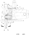
次に、前記した第1〜第6の発明及び関連発明の実施形態を図1〜図10に基づいて説明する。図1は、携帯丸鋸と称される切断機1が示されている。この切断機1は、切断材Wの上面に乗せ掛けるベース2と、このベース2の上面側に支持された切断機本体10を備えている。切断機本体10は、本体ケース11の背面に駆動源としての電動モータ12を備えている。この電動モータ12の回転出力は減速ギヤ列13を経てスピンドル14に伝達される。減速ギヤ列13は、相互に噛み合わされた電動モータ12のピニオンギヤ12aと駆動ギヤ13aから構成されており、ギヤボックス18内に収容されている。駆動ギヤ13aがスピンドル14上に固定されている。このスピンドル14は、ベアリング15,16を介して本体ケース11に回転可能に支持されている。正面側のベアリング15はベアリングボックス17の内周側に保持されている。同じくベアリングボックス15の内周側であってこのベアリング15の前側には防塵用のシール部材15aが取り付けられている。背面側のベアリング16はギヤボックス18に保持されている。ギヤボックス18の正面側にベアリングボックス17が取り付けられている。
スピンドル14の先端側は、ベアリングボックス17から突き出されて本体ケース11の内部に至っている。このスピンドル14の先端部に円形の切断刃20が取り付けられている。切断刃20は、アウタ側の固定フランジ21とインナ側の固定フランジ22で板厚方向に挟まれた状態で、軸方向及び回転方向に強固に固定された状態でスピンドル14に取り付けられている。固定フランジ21,22の挟み込み状態は、スピンドル14の先端に締め込んだ固定ねじ23によって強固に固定されている。
切断刃20の上側ほぼ半周の範囲の周縁部(刃先)は、本体ケース11のカバー部11aに覆われている。切断刃20の下側ほぼ半周の範囲は、ベース2に設けた窓部2aを経てベース2の下面側へ突き出されている。切断刃20の、ベース2の下面側に突き出された部分が切断材Wに切り込まれる。
Next, embodiments of the first to sixth inventions and related inventions will be described with reference to FIGS. FIG. 1 shows a cutting
The tip end side of the
A peripheral edge (cutting edge) in the range of approximately a half circumference on the upper side of the
切断刃20の、ベース2の下面側に突き出された範囲の周縁部(刃先)は、可動カバー25で覆われている。この可動カバー25は、ベアリングボックス17に回転可能に支持されている。この可動カバー25は、切断刃20の、ベース2の下面側に突き出された範囲で刃先の全周を覆う閉じ位置と、刃先の全周を露出させる全開位置との間を開閉可能に支持されている。
この可動カバー25とこれを支持するベアリングボックス17の詳細が図2に示されている。可動カバー25は、切断刃20の刃先を覆う断面U字形のカバー部25aと、このカバー部25aをベアリングボックス17に支持する円筒形状の支持円環部25bを備えている。この支持円環部25bの内周側にベアリングボックス17の回転ボス部17aが挿入されて、当該可動カバー25がスピンドル14と同軸で回転可能に支持されている。回転ボス部17aの外径寸法に対して支持円環部25bの内径寸法は、当該可動カバー25のスムーズな回転動作を阻害しない範囲でがたつきが発生しないように適切に設定されており、両者間のクリアランスは極力小さくなるように寸法設定されている。
支持円環部25bとベアリングボックス17との間には、引っ張りばね24が介装されている。この引っ張りばね24によって可動カバー25は、閉じ方向に付勢されている。可動カバー25の先端部を切断材Wの切り込み端部に当接させ、この当接状態で当該切断機1を切断進行方向に移動させると、可動カバー25が引っ張りばね24に抗して相対的に開かれて切断刃20の露出範囲が徐々に拡大して切断材Wに切り込まれていく。
ベアリングボックス17の外周であって回転ボス部17aの背面側には軸方向規制部17bが段付き状に形成されている。また、ベアリングボックス17の外周であって回転ボス部17aの正面側には止め輪19が装着されている。支持円環部25bは、軸方向規制部17bとこの止め輪19によって軸方向の変位が規制されている。従って、止め輪19は、支持円環部25bの正面側への変位を規制する軸方向規制部として機能する。支持円環部25bと止め輪19との間には、円形平板形のワッシャ19aが挟み込まれている。
The peripheral edge (blade edge) of the
Details of the
A
An axial
このように、支持円環部25bが軸方向規制部としての止め輪19と軸方向規制部17b間に挟まれて軸方向への変位(がたつき)が規制されていることにより、可動カバー25の切断進行方向左右方向(図1において矢印X方向)への振れ(がたつき)が規制されている。
支持円環部25bとベアリングボックス17との間には、両者間への切断粉等の粉塵の侵入を防止するための防塵構造を備えている。以下、この防塵構造について種々の実施形態を説明する。第1実施形態の防塵構造30は、支持円環部25bの正面側端面とワッシャ19aとの間にリングスプリング31を挟み込んだ構成を備えている。第1実施形態の場合、このリングスプリング31が特許請求の範囲に記載した弾性部材に相当する。このリングスプリング31は、摺動性が高く摩擦係数の小さな高強度樹脂(例えば、ポリアセタール)を素材として円環形状(C字形)に成形されたもので、縮径方向に付勢力を有している。このリングスプリング31は、支持円環部25bの正面側端面に設けた円環形状の凹部25c内に沿って嵌め込まれている。図3に示すように、この凹部25cの小径側(図3において下側)の側壁部と底部との間には、傾斜面25dが形成されている。この傾斜面25dは、外周側(図3において上側)の側壁部に向かって下る方向に傾斜している。
リングスプリング31は、当該支持円環部25bが軸方向規制部としての止め輪19と軸方向規制部17bとの間に挟まれて軸方向の変位が規制されることにより、凹部25c内へ押し込まれる状態で装着され、従って傾斜面25dに押し付けられた状態で装着されている。このため、リングスプリング31は、その付勢力に抗して拡径方向へ変位した状態で凹部25c内に保持されており、その結果リングスプリング31は傾斜面25dに対するその付勢力の軸方向成分によってワッシャ19a(止め輪19側)に押し付けられた状態となっている。
リングスプリング31の傾斜面25dに対する押圧面とワッシャ19aに対する押圧面はそれぞれ全周にわたって平坦面31a,31bに形成されている。このため、リングスプリング31は、傾斜面25d及びワッシャ19aに対してそれぞれ面当たり状態で押圧されている。このように、当該リングスプリング31の断面形状が単に円形ではなく、全周にわたって平たん面31a,31bが形成されて、それぞれが傾斜面25dとワッシャ19aに対して面当たり状態で押圧される構成であることから、高い摺動性を確保しつつ押圧力を確実に伝達してスムーズに拡径方向及び縮径方向に変形させることができ、ひいては支持円環部25bの軸方向の弾性力を確実に発揮してそのがたつきを抑制するとともに、粉塵の遮断機能(防塵機能)を確実に発揮させることができるようになっている。
As described above, the
A dust-proof structure is provided between the
The
The pressing surface for the
このように構成した第1実施形態の防塵構造30によれば、支持円環部25bの凹部25cとワッシャ19aとの間にリングスプリング31がその全周にわたって弾性的に押し付けられることにより、粉塵発生側(切断刃20側)から支持円環部25bの内周側に至る粉塵の侵入経路がその途中で遮断されて支持円環部25bの内周側への粉塵の侵入が防止されるようになっている。このようにリングスプリング31によって支持円環部25bの内周側及びその周辺に対する防塵が確実になされることから、当該支持円環部25bひいては可動カバー25のベアリングボックス17に対するスムーズな回転動作を確保するために必要かつ十分なクリアランスを設定しても高い防塵性を確保することができる。このことから、第1実施形態の防塵構造30によれば、従来のような特別のベアリング(第2ベアリング)を省略することにより、当該可動カバー25の支持構造について低コスト化を図りつつ高い防塵性を確保することができる。
また、摺動性の高いリングスプリング31をワッシャ19aを介して軸方向規制部としての止め輪19に押圧して防塵する構成であるので、規格品である止め輪を軸方向規制部として用いる場合に、より大径のリングスプリング31を任意サイズに加工できるワッシャを介して当該止め輪に押圧させることができ、従って利用できるリングスプリングのサイズについて選択の自由度が高まる。
以上説明した第1実施形態には種々変更を加えることができる。例えば、図4に示すように可動カバー25の支持円環部25bとベアリングボックス17との間に中間スリーブ32を介装する構成(第2実施形態)としてもよい。この中間スリーブ32は、リングスプリング31と同様摺動性の高い(摩擦抵抗の小さい)高強度樹脂を素材として成型されたもので、支持円環部25bの内周面とベアリングボックス17の回転ボス部17aとの間に挟まれた円筒部32aと、この円筒部32aの背面側端部から張り出して、支持円環部25bの背面側端部とベアリングボックス17の軸方向規制部17bとの間に挟まれたフランジ部32bを備えている。この中間スリーブ32は、回転ボス部17aの外周側に固定されて軸回り及び軸方向に位置ずれしないようになっている。
この第2実施形態の防塵構造33によれば、可動カバー25の支持円環部25bと中間スリーブ32の円筒部32aとの間のクリアランスを一層小さく設定して防塵性を高めつつ、両者25b,32a間のがたつきを抑制して可動カバー25のよりスムーズな開閉動作を実現することができる。
According to the
In addition, since the
Various modifications can be made to the first embodiment described above. For example, as shown in FIG. 4, the
According to the
図5にはさらに変更を加えた第3実施形態の防塵構造40が示されている。この第3実施形態の防塵構造40では、弾性部材として前記第1及び第2実施形態におけるリングスプリング31に代えて2つのゴムリング42,43を用いた構成となっている。第1又は第2実施形態と同様で足り、特に変更を要しない部材及び構成については同位の符号を用いてその説明を省略する。
スピンドル14の正面側はベアリング15で回転支持されている。このベアリング15は、ベアリングケース17に保持されている。ベアリングケース17の回転ボス部17aに、可動カバー41の支持円環部41aが回転可能に支持されている。支持円環部41aは、第1及び第2実施形態と同様円筒形状を有するもので、ベアリングケース17の軸方向規制部17bと止め輪19によって軸方向両側への変位を規制されている。また、支持円環部41aの内径寸法と回転ボス部17aの外径寸法は、当該可動カバー41に振れ(図1中矢印X方向の変位)を発生させない範囲でスムーズな回転動作が得られる寸法に設定されている。
支持円環部41aの正面側端面と止め輪19との間には、第1及び第2実施形態と同様ワッシャ19aが挟み込まれている。支持円環部41aの正面側及び背面側の両端面に、それぞれ円環形状のゴムリング42,43が装着されている。本実施形態の場合、このゴムリング42,43には、Oリング(オーリング)と称される安価な部材が用いられており、前記リングスプリング31を用いる構成に比して低コスト化が図られている。両ゴムリング42,43は、それぞれ支持円環部41aの両端面に形成した凹部41b,41c内に嵌め込まれている。両凹部41b,41c内には前記第1及び第2実施形態と同様傾斜面が形成されており、この傾斜面にそれぞれゴムリング42,43が押し付けられている。このため、正面側のゴムリング42はワッシャ19aにより凹部41bの傾斜面に適度な押し付け力で押し付けられて拡径方向に押し拡げられた状態で装着され、背面側のゴムリング43は軸方向規制部17bにより凹部41cの傾斜面に適度な押し付け力で押し付けられて拡径方向に押し広げられた状態で装着されており、その結果それぞれ押し付けによる反力でワッシャ19a及び軸方向規制部17bに弾性的に押し付けられた状態となっている。
第3実施形態の場合、このように装着された2つのゴムリング42,43によって、切断刃20側(粉塵発生側)から支持円環部41aの内周側に至る粉塵の侵入経路が正面側及び背面側の両側においてその途中で遮断された構成となっている。
このように構成した第3実施形態の防塵構造40によれば、2つのゴムリング42,43によって支持円環部41aの内周側及びその周辺への粉塵の侵入を防止することができる。このため、支持円環部41aとベアリングケース17の支持ボス部17aとの間に、可動カバー41のスムーズな開閉動作を確保するために必要かつ十分なクリアランスを設定しても高い防塵性を確保することができ、従って従来の可動カバー回転支持用のベアリングを省略することにより当該支持構造の低コスト化を図ることができる。
FIG. 5 shows a
The front side of the
A
In the case of the third embodiment, the two
According to the
図6には、第4実施形態に係る防塵構造50が示されている。この第4実施形態は、前記第1〜第3実施形態の弾性部材シール構造とは異なって、ラビリンス構造を主体とする防塵構造で、関連発明の実施形態に相当する。第1〜第3実施形態と同様の部材及び構成については同位の符号を用いて説明を省略する。
前記各実施形態と同様、可動カバー51の支持円環部51aは、ベアリングボックス52の回転ボス部52aに回転可能に支持されている。可動カバー51は、その支持円環部51aとベアリングボックス52との間に装着した引っ張りばね24によって閉じ方向に付勢されている。
支持円環部51aは、その正面側への変位がベアリングボックス52に装着した止め輪19によって規制され、背面側への変位がベアリングボックス52の背面側端部に設けた軸方向規制部52bによって規制されている。
支持円環部51aの正面側端面には、凹部51cが全周にわたって設けられている。この凹部51c内には、防塵ワッシャ53の周縁部が進入している。防塵ワッシャ53は、スピンドル14のフランジ部14aとインナ側の固定フランジ22との間に挟み込まれてスピンドル14と一体で回転する。防塵ワッシャ53の周縁部は背面側へ直角に屈曲しており、この屈曲部53aが凹部51c内に接触しない範囲で進入している。防塵ワッシャ53の屈曲部53aが凹部51c内に進入することにより、切断刃20側から支持円環部51aの内周側へ至る粉塵の侵入経路の途中が屈曲されてラビリンス構造(経路屈曲構造)が構成されており、これにより当該支持円環部51aの正面側端面と止め輪19との間の隙間及び支持円環部51aの内周側の防塵がなされるようになっている。
FIG. 6 shows a
As in the above embodiments, the
The
A
ベアリングボックス52の軸方向規制部52bには、その全周にわたって防塵縁52cが正面側に張り出す状態に設けられている。図示するようにこの防塵縁52cは、支持円環部51aの背面側端部の外周側を覆う状態に張り出している。このため、この防塵縁52cによって、支持円環部51aの背面側端部と軸方向規制部52bとの間の隙間が切断刃20側(粉塵発生側)から遮蔽され、これにより当該支持円環部51aの背面側端部と軸方向規制部52b間の隙間及び支持円環部51aの内周側の防塵がなされるようになっている。
防塵ワッシャ53の正面側周縁には、複数のフィン53b〜53bが正面側へ張り出す状態に設けられている。この複数のフィン53b〜53bは、周方向等間隔に配置されて、固定フランジ22に干渉しない範囲で正面側に張り出している。この複数のフィン53b〜53bによって、当該防塵ワッシャ53がスピンドル14と一体で回転することにより防塵ファンとして機能する。
このように第4実施形態の防塵構造50によれば、可動カバー51の支持円環部51aの正面側が防塵ワッシャ53の屈曲部53aで切断刃20側から遮蔽され、背面側がギヤボックス52の防塵縁52cで切断刃20側からそれぞれ遮蔽されている。このため、支持円環部51aの正面側端部と止め輪19との間の隙間、背面側端部と軸方向規制部52bとの間の隙間への粉塵の侵入が防止され、ひいては支持円環部51aの内周側への粉塵の侵入が防止される。このことから、従来の特別のベアリング(第2のベアリング)を用いることなく、高い防塵性を確保しつつ、当該可動カバー51のスムーズな開閉動作を確保するために必要かつ十分なクリアランスを支持円環部51aとベアリングボックス52の回転ボス部52aとの間に設定することができ、これによりコスト低減を図ることができる。
また、第4実施形態の防塵構造50によれば、スピンドル14と一体で回転する防塵ワッシャ53を防塵ファンとして機能させることができることから、切断刃20側で発生した粉塵が支持円環部51a側へ吹き付けられることを低減することができ、この点でも当該支持円環部51aのベアリングボックス52に対する回転支持部の高い防塵性を確保することができる。
さらに、第4実施形態の防塵構造50によれば、支持円環部51aに対して、防塵ワッシャ53の屈曲部53a及びベアリングボックス52の防塵縁52cが共に非接触であるので、支持円環部51aのベアリングボックス52に対する回転動作ひいては可動カバー51のスムーズな開閉動作が阻害されることがない。
A dust-
A plurality of
As described above, according to the dust-
Further, according to the
Further, according to the
図7には、上記第4実施形態にさらに変更を加えた第5実施形態に係る防塵構造60が示されている。この第5実施形態の防塵構造60では、第4実施形態の防塵ワッシャ53に代えて防塵ファン61を備えている点で第4実施形態とは異なっている。第4実施形態と同様の部材及び構成については同位の符号を用いてその説明を省略する。
第5実施形態の場合、防塵ファン61は、インナ側の固定フランジ22の周囲に一体に設けられている。このため、防塵ファン61は、スピンドル14と一体で回転する。この防塵ファン61の周囲には、複数のフィン61a〜61aが設けられている。図示するように各フィン61aは、その外周側ほど背面側に長く延びる形状を有している。各フィン61aの背面側突出部61bが、支持円環部51aの正面側端部に設けた凹部51c内に干渉しない範囲で進入している。
このように構成した第5実施形態の防塵構造60によれば、スピンドル14と一体で防塵ファン61が回転する。このため、防塵ファン61の各フィン61aの背面側突出部61bが凹部51c内に沿って高速で移動するため、支持円環部51aの正面側端面と止め輪19との間の隙間の外周側(切断刃20側)が防塵ファン61のフィン61a〜61aによって実質的に遮蔽された状態となる。このように、支持円環部51aの正面側端面とこれの正面側への変位を規制する止め輪19との間の隙間が高速で回転する各フィン61aの背面側突出部61bによって切断刃20側から遮蔽されるとともに、支持円環部51aの背面側端面とこれの背面側への変位を規制する軸方向規制部52bとの間の隙間が第4実施形態と同様防塵縁52cによって同じく回転刃20側から遮蔽されて、当該支持円環部51aの内周側への粉塵の侵入が防止される。このため、第5実施形態の防塵構造60によっても、支持円環部51aのベアリングボックス52に対する回転支持部の高い防塵性を確保しつつ、従来の第2のベアリングを省略してそのコスト低減を図ることができる。
また、第5実施形態によっても、切断刃20側で発生した粉塵が防塵ファン61によって吹き飛ばされることから、この点でも支持円環部51a付近の高い防塵性を確保することができる。
FIG. 7 shows a
In the case of the fifth embodiment, the
According to the
Also, according to the fifth embodiment, since dust generated on the
図8には、第6実施形態の防塵構造70が示されている。この第6実施形態は、弾性部材シール構造とラビリンス構造の双方を併せ持つ形態で、防塵性能が一層高められている。前記各実施形態と同様の部材及び構成については同位の符号を用いてその説明を省略する。第6実施形態の防塵構造70では、可動カバー71の支持円環部71aとベアリングボックス72の構成に特徴を有している。可動カバー71の支持円環部71aは、ベアリングボックス72の回転ボス部72aに回転可能に支持されている。支持円環部71aの正面側への変位は止め輪19によって規制されている。支持円環部71aの背面側への変位は、ベアリングボックス72に設けた軸方向規制部72bによって規制されている。
支持円環部71aの正面側には、リング形の防塵カバー73が取り付けられている。この防塵カバー73によって、止め輪19と支持円環部71aの正面側端面との間の隙間が切断刃20側(粉塵発生側)から遮蔽されている。
支持円環部71aには、背面側に張り出す第2防塵壁部71bが一体に設けられている。この第2防塵壁部71bは、支持円環部71aの外周側に沿って円筒形状に形成されている。一方、ベアリングボックス72の軸方向規制部72bにも、円筒形状の第1防塵壁部72cが正面側へ張り出す状態で一体に設けられている。ベアリングボックス72側の第1防塵壁部72cは、支持円環部71a側の第2防塵壁部71bの内周側に侵入している。
ベアリングボックス72の軸方向規制部72bの正面側であって第1防塵壁部72cの外周側には、第1実施形態の凹部25cと同様の凹部72dが形成されている。第1実施形態と同様この凹部72d内には、一つの円環形状のリングスプリング74が嵌め込まれている。この凹部72dの内周側の側壁部と底部との間には傾斜面が形成されており、この傾斜面にリングスプリング74が押し付けられている。このリングスプリング74は、支持円環部71a側の第2防塵壁部71bによって凹部72d内の傾斜面に押し付けられてその付勢力に抗して拡径方向に変位しており、その反力の軸方向成分によって第2防塵壁部71bの先端面に押し付けられている。
支持円環部71aとベアリングボックス72との間には、可動カバー71を閉じ側へ付勢するための引っ張りばね24が介装されている。第6実施形態の場合、この引っ張りばね24は、支持円環部71a側の第2防塵壁部71bの外周面に沿って介装されている。
FIG. 8 shows a
A ring-shaped dustproof cover 73 is attached to the front side of the
The
A
A
以上のように構成した第6実施形態の防塵構造70によれば、支持円環部71aの正面側端面と止め輪19との間の隙間が防塵ワッシャ73によって切断刃20側(粉塵発生側)から遮蔽されて、その防塵がなされる。また、支持円環部71aの背面側と軸方向規制部72bとの間の隙間が第2防塵壁部71bと第1防塵壁部72cによって切断刃20側から遮蔽されて、その防塵がなされる。このため、支持円環部71aとベアリングボックス72の回転ボス部72aとの間に可動カバー71のスムーズな開閉動作を確保するために必要かつ十分なクリアランスを設定しても、両者間の高い防塵性を確保することができる。このため、従来の特別な第2のベアリングを省略することによりコストの低減を図ることができる。
また、支持円環部71a側の第2防塵壁部71bと、ベアリングボックス72の軸方向規制部72bとの間のクリアランスがリングスプリング74によってシールされていることから、一層高い防塵性を実現できる。さらに、支持円環部71a側の第2防塵壁部71bと、ベアリングボックス72側の防塵壁部72によって、切断刃20側から支持円環部71aの内周側へ至る粉塵の侵入経路の途中においてより複雑な屈曲経路(ラビリンス構造)が形成されているため、この点でも支持円環部71aの内周側への粉塵の侵入を確実に防止することができる。
According to the
Further, since the clearance between the second dust-
以上説明した各実施形態にはさらに変更を加えることができる。例えば、第1実施形態において、凹部25c内に傾斜面25dを設けてリングスプリング31を拡径方向に変位させる構成を例示したが、これに代えてあるいは加えて止め輪19側若しくはワッシャ19a側に傾斜面を設けて弾性部材としてのリングスプリング31をより確実に拡径方向に変位させる構成としてもよい。
また、第1実施形態では、支持円環部25bの前側端面(凹部25c)と前側の軸方向規制部としての止め輪19との間にリングスプリング31を介在させる構成を例示したが、これに代えてあるいは加えて支持円環部25bの後ろ側端面と後ろ側の軸方向規制部17bとの間にリングスプリング31を介在させる構成としてもよい。係る構成が図9及び図10に示されている。
図9に示す防塵構造80は、支持円環部25bの後面に凹部81を設け、この凹部81の口元角部81aを、弾性部材82の平坦面82aに押し当てる構成を備えている。支持円環部25bの前側については第1実施形態の防塵構造30が構成されている。この防塵構造80によっても弾性部材82の平たん面82a(傾斜面)が支持円環部25bと軸方向規制部17bとの間で押圧されることにより当該弾性部材82が拡径方向へ変位し、これにより前側の防塵構造30とも相まって支持円環部25bの内周側への粉塵侵入経路が確実に遮断されるとともに、可動カバー25のスムーズな開閉動作を確保することができる。この場合、弾性部材82の平坦面82aが、当該弾性部材82を拡径方向へ変位させるための傾斜面として機能する。
なお、凹部81の外周側壁部83(図9において破線の右側に示す部分)を取り除いた段付き形状の凹部としてもよい。また、支持円環部25bの後面に、後方(弾性部材側)へ張り出す円環形の壁部を設けて、この壁部の角部を弾性部材の傾斜面に押圧する構成とすることにより凹部を省略する構成としてもよい。
図10に示す防塵構造90では、支持円環部25bの後面に後方へ張り出す円環形の壁部91が設けられ、この壁部91が弾性部材92を拡径方向へ変位させるための傾斜面91aを備えた構成となっている。弾性部材92は、軸方向規制部17bに設けた凹部93内に収容されている。この防塵構造90によっても弾性部材92が支持円環部25b側の傾斜面91aと軸方向規制部17b側の凹部93との間で押圧されることにより拡径方向に変位し、これにより前側の防塵構造30とも相まって支持円環部25bの内周側への粉塵侵入経路が遮断されるとともに、可動カバー25のスムーズな開閉動作を確保することができる。なお、この場合にも、凹部93の外周側壁部94(図10において破線の左側に示す部分)を取り除いた段付き形状の凹部としてもよい。
さらに、同じく第1実施形態において、リングスプリング31の傾斜面25dに対する押圧面を平坦面31aに形成して面当たり状態で押圧し、またリングスプリング31の軸方向規制部としての止め輪19(ワッシャ19a)に対する押圧面を平坦面31bに形成して面当たり状態で押圧させる構成を例示したが、これらの平坦面31a,31bを省略してもよい。
また、切断機として、使用者が切断材W上を移動させて切断加工を行う携帯形の切断機を例示したが、例示した各防塵構造は、テーブル上に固定した切断材に対して切断機本体を下動させて切断刃を切り込む卓上形の切断機についても同様に適用することができる。
Each embodiment described above can be further modified. For example, in the first embodiment, the configuration in which the
Further, in the first embodiment, the configuration in which the
The dust-proof structure 80 shown in FIG. 9 has a configuration in which a concave portion 81 is provided on the rear surface of the
In addition, it is good also as a recessed part of the step shape which remove | excluded the outer peripheral side wall part 83 (part shown in the right side of a broken line in FIG. 9) of the recessed part 81. FIG. Further, an annular wall portion projecting rearward (to the elastic member side) is provided on the rear surface of the support
In the
Further, in the first embodiment as well, a pressing surface against the
Moreover, although the portable cutting machine which a user moves on the cutting material W and performed cutting processing was illustrated as a cutting machine, each illustrated dustproof structure is a cutting machine with respect to the cutting material fixed on the table. The present invention can be similarly applied to a table-type cutting machine that lowers the main body and cuts the cutting blade.
W…切断材
1…切断機(携帯丸鋸)
2…ベース、2a…窓部
10…切断機本体
11…本体ケース、11a…カバー部
12…電動モータ、12a…ピニオンギヤ
13…減速ギヤ列、13a…駆動ギヤ
14…スピンドル、14a…フランジ部
15,16…ベアリング、15a…シール部材
17…ベアリングボックス、17a…回転ボス部、17b…軸方向規制部
18…ギヤボックス
19…止め輪、19a…ワッシャ
20…切断刃
21…固定フランジ(アウタ側)
22…固定フランジ(インナ側)
23…固定ねじ
24…引っ張りばね
25…可動カバー
25a…カバー部、25b…支持円環部、25c…凹部、25d…傾斜面
30…防塵構造(第1実施形態)
31…リングスプリング
32…中間スリーブ、32a…円筒部、32b…フランジ部
33…防塵構造(第2実施形態)
40…防塵構造(第3実施形態)
41…可動カバー、41a…支持円環部、41b,41c…凹部
42,43…ゴムリング
50…防塵構造(第4実施形態)
51…可動カバー、51a…支持円環部、51c…凹部
52…ベアリングボックス
52a…回転ボス部、52b…軸方向規制部、52c…防塵縁
53…防塵ワッシャ、53a…屈曲部、53b…フィン
60…防塵構造(第5実施形態)
61…防塵ファン、61a…フィン、61b…背面側突出部
70…防塵構造(第6実施形態)
71…可動カバー、71a…支持円環部、71b…第2防塵壁部
72…ベアリングボックス
72a…回転ボス部、72b…軸方向規制部、72c…第1防塵壁部、72d…凹部
73…防塵カバー
74…リングスプリング
W ... Cutting
DESCRIPTION OF
22: Fixed flange (inner side)
DESCRIPTION OF
31 ...
40 ... Dust-proof structure (third embodiment)
41 ... movable cover, 41a ... support ring part, 41b, 41c ...
51 ... movable cover, 51a ... support ring, 51c ... concave 52 ... bearing
61 ... dust-proof fan, 61a ... fin, 61b ...
71 ... Movable cover, 71a ... Supporting ring part, 71b ... Second
Claims (8)
前記切断刃は、前記本体ケースのベアリングボックスに収容したベアリングにより回転支持されたスピンドルに取り付けられており、
前記可動カバーは円筒形の支持円環部を備え、該支持円環部を前記ベアリングボックスの外周側に回転可能に支持して前記刃先を開閉可能に回転支持されており、
前記可動カバーの支持円環部は、前記ベアリングボックス部に設けた軸方向規制部により当該軸方向両側への変位が規制されており、
該支持円環部の軸方向端面と前記軸方向規制部との間に円環形状の弾性部材を押圧状態で介装して、前記切断刃側から前記支持円環部の内周側に至る粉塵の侵入経路を遮断する構成とした防塵構造。 A base to be brought into contact with the upper surface of the cutting material, and a cutting machine main body supported on the upper surface side of the base, the cutting machine main body having a main body case and a circular cutting blade rotated by an electric motor; The upper part of the cutting blade is covered with the main body case, the lower part of the cutting blade is protruded to the lower surface side of the base, and the cutting edge of the protruding part is covered with the movable cover so as to be opened and closed. A dust-proof structure of the rotation support part for the main body case,
The cutting blade is attached to a spindle that is rotatably supported by a bearing accommodated in a bearing box of the main body case,
The movable cover includes a cylindrical support ring part, and the support ring part is rotatably supported on the outer peripheral side of the bearing box so that the blade edge can be opened and closed.
The support ring part of the movable cover is restricted from being displaced in the axial direction by the axial restriction part provided in the bearing box part,
An annular elastic member is interposed between the axial end face of the support ring part and the axial restriction part in a pressed state, and reaches from the cutting blade side to the inner peripheral side of the support ring part. A dust-proof structure that blocks the dust entry path.
前記支持円環部が外周に配置される回転ボス部を設け、かつ、前記支持円環部の軸方向への移動が規制される軸方向規制部を設け、該軸方向規制部と前記支持円環部との間に、円環形状の弾性部材を配置したことを特徴とする切断機。 A motor, a main body case provided with the motor, a cutting blade rotated by the motor, and a movable cover that covers the cutting edge of the cutting blade protruding from the main body case so as to be openable and closable and has a support ring portion And a cutting machine having
The support ring portion is provided with a rotating boss portion arranged on the outer periphery, and an axial direction restriction portion is provided for restricting movement of the support ring portion in the axial direction. The axial direction restriction portion and the support circle A cutting machine in which an annular elastic member is disposed between the ring portion.
前記ベアリングボックスに、前記支持円環部が外周に配置される回転ボス部、及び第1の端部を設け、前記支持円環部の軸方向に第2の端部を設け、前記第1の端部及び前記第2の端部に隙間を設け、前記隙間に弾性体を配置したことを特徴とする切断機。
A motor, a main body case including the motor, a spindle rotated by the motor, a cutting blade held by the spindle, and a cutting edge of the cutting blade protruding from the main body case so as to be openable and closable. A cutting machine comprising: a movable cover having a support ring portion; a bearing for holding the spindle; and a bearing box for holding the bearing,
The bearing box is provided with a rotating boss portion on which the support ring portion is disposed on the outer periphery, and a first end portion, and a second end portion is provided in the axial direction of the support ring portion, and the first A cutting machine, wherein a gap is provided in an end portion and the second end portion, and an elastic body is disposed in the gap.
Priority Applications (5)
| Application Number | Priority Date | Filing Date | Title |
|---|---|---|---|
| JP2009271534A JP5501743B2 (en) | 2009-11-30 | 2009-11-30 | Dust-proof structure of movable cover support in cutting machine |
| PCT/JP2010/069809 WO2011065214A1 (en) | 2009-11-30 | 2010-11-08 | Dustproof structure for movable support section in cutting machine |
| CN201080058138.7A CN102665984B (en) | 2009-11-30 | 2010-11-08 | Dustproof structure for movable support section in cutting machine |
| US13/510,457 US8813375B2 (en) | 2009-11-30 | 2010-11-08 | Dust-proof structure of movable cover supporting portion of cutting machine |
| EP10833061.4A EP2508285B1 (en) | 2009-11-30 | 2010-11-08 | Dustproof structure for movable support section in cutting machine |
Applications Claiming Priority (1)
| Application Number | Priority Date | Filing Date | Title |
|---|---|---|---|
| JP2009271534A JP5501743B2 (en) | 2009-11-30 | 2009-11-30 | Dust-proof structure of movable cover support in cutting machine |
Publications (3)
| Publication Number | Publication Date |
|---|---|
| JP2011110685A JP2011110685A (en) | 2011-06-09 |
| JP2011110685A5 JP2011110685A5 (en) | 2012-10-11 |
| JP5501743B2 true JP5501743B2 (en) | 2014-05-28 |
Family
ID=44066317
Family Applications (1)
| Application Number | Title | Priority Date | Filing Date |
|---|---|---|---|
| JP2009271534A Active JP5501743B2 (en) | 2009-11-30 | 2009-11-30 | Dust-proof structure of movable cover support in cutting machine |
Country Status (5)
| Country | Link |
|---|---|
| US (1) | US8813375B2 (en) |
| EP (1) | EP2508285B1 (en) |
| JP (1) | JP5501743B2 (en) |
| CN (1) | CN102665984B (en) |
| WO (1) | WO2011065214A1 (en) |
Families Citing this family (3)
| Publication number | Priority date | Publication date | Assignee | Title |
|---|---|---|---|---|
| JP2014079874A (en) * | 2012-09-26 | 2014-05-08 | Makita Corp | Power tool |
| CN110199069B (en) * | 2017-01-10 | 2022-07-12 | 株式会社牧田 | Binding machine |
| DE102020100574B4 (en) * | 2020-01-13 | 2024-02-08 | Festool Gmbh | Guide rail for guiding a hand-held machine tool |
Family Cites Families (19)
| Publication number | Priority date | Publication date | Assignee | Title |
|---|---|---|---|---|
| US1672238A (en) * | 1926-08-13 | 1928-06-05 | J D Wallace & Company | Electric handsaw |
| US4685214A (en) * | 1985-10-04 | 1987-08-11 | Fmc Corporation | Protective guard unit for metal working tool |
| JPS6441901U (en) * | 1987-09-07 | 1989-03-13 | ||
| JPH0727121Y2 (en) * | 1988-09-14 | 1995-06-21 | 日立工機株式会社 | Portable dust collecting circular saw |
| JP2501707Y2 (en) * | 1989-10-14 | 1996-06-19 | 日立工機株式会社 | Portable electric cutting tool |
| US5023999A (en) * | 1990-08-09 | 1991-06-18 | Ryobi Motor Products Corp. | Unitized tool construction |
| US5140754A (en) * | 1991-09-24 | 1992-08-25 | Textron Inc. | Power tool protective hood positioning system and method of manufacturing the same |
| JP2584955Y2 (en) * | 1993-07-29 | 1998-11-11 | 日立工機株式会社 | Circular saw |
| SE506590C2 (en) * | 1996-05-13 | 1998-01-19 | Electrolux Ab | Explosion protection for circular tool |
| JP2001047407A (en) * | 1999-08-10 | 2001-02-20 | Makita Corp | Portable motor-driven circular sawing machine |
| JP2003251601A (en) * | 2002-03-05 | 2003-09-09 | Ryobi Ltd | Motor-driven tool |
| US6739060B1 (en) * | 2003-04-29 | 2004-05-25 | Durq Machinery Corp. | Sawing machine with dustproof assembly |
| JP2005001896A (en) | 2003-06-09 | 2005-01-06 | Fuji Heavy Ind Ltd | Glass cutting device |
| SE528265C2 (en) * | 2005-02-18 | 2006-10-10 | Mats Johansson | Cutting and dust collection units and work machine with such units |
| US20080011138A1 (en) * | 2006-07-13 | 2008-01-17 | Brazell Kenneth M | Portable power tool for cutting concrete board and other substrates |
| JP4780528B2 (en) * | 2006-09-20 | 2011-09-28 | 日立工機株式会社 | Tabletop cutting machine |
| US20080066323A1 (en) * | 2006-09-20 | 2008-03-20 | Crain Cutter Company, Inc. | Yieldable drive mechanism for a toe-kick saw |
| JP2008188716A (en) * | 2007-02-06 | 2008-08-21 | Yamashin Seikyo Kk | Circular saw cutter |
| US8037610B2 (en) * | 2008-12-30 | 2011-10-18 | Crain Cutter Co., Inc. | Powered groover with airflow fin |
-
2009
- 2009-11-30 JP JP2009271534A patent/JP5501743B2/en active Active
-
2010
- 2010-11-08 EP EP10833061.4A patent/EP2508285B1/en active Active
- 2010-11-08 CN CN201080058138.7A patent/CN102665984B/en active Active
- 2010-11-08 WO PCT/JP2010/069809 patent/WO2011065214A1/en active Application Filing
- 2010-11-08 US US13/510,457 patent/US8813375B2/en active Active
Also Published As
| Publication number | Publication date |
|---|---|
| US8813375B2 (en) | 2014-08-26 |
| CN102665984A (en) | 2012-09-12 |
| EP2508285A4 (en) | 2015-07-29 |
| EP2508285B1 (en) | 2018-01-03 |
| US20120240416A1 (en) | 2012-09-27 |
| JP2011110685A (en) | 2011-06-09 |
| EP2508285A1 (en) | 2012-10-10 |
| CN102665984B (en) | 2014-07-16 |
| WO2011065214A1 (en) | 2011-06-03 |
Similar Documents
| Publication | Publication Date | Title |
|---|---|---|
| JP6034812B2 (en) | Bush bearing structure | |
| JP6332463B2 (en) | Electric power steering device | |
| JP5501743B2 (en) | Dust-proof structure of movable cover support in cutting machine | |
| EP3081335B1 (en) | Guard assembly for a power tool | |
| WO2016088659A1 (en) | Mechanical seal apparatus | |
| WO2018043330A1 (en) | Working machine | |
| WO2011048950A1 (en) | Shock absorbing mechanism for gear train | |
| JP6282918B2 (en) | Motor actuator | |
| JP2007139045A (en) | Rotating shaft seal and bearing device | |
| JP2011110685A5 (en) | ||
| WO2017154522A1 (en) | Desk-top cutting machine | |
| JP2016016469A (en) | Rotary tool | |
| JP4890879B2 (en) | Dust-proof structure of power tools | |
| JP2020128609A (en) | Visor locking mechanism and helmet | |
| JP6943584B2 (en) | Grinder | |
| JPH10109247A (en) | Rotation preventing device for tool rotatively borne of working apparatus | |
| JP2010025253A (en) | Sealing device for rolling bearing | |
| JP2008156818A (en) | Gear damper | |
| JP5403622B2 (en) | Dustproof cover for fan gear | |
| JP2018001504A (en) | Chain saw | |
| JP4687090B2 (en) | Auto tensioner | |
| JP2006029536A (en) | Auto tensioner | |
| JP6469607B2 (en) | Cup holder | |
| JP6445338B2 (en) | Seat reclining device | |
| JP2016138340A (en) | Fitting structure of antifog sheet to shield |
Legal Events
| Date | Code | Title | Description |
|---|---|---|---|
| A521 | Request for written amendment filed |
Free format text: JAPANESE INTERMEDIATE CODE: A523 Effective date: 20120829 |
|
| A621 | Written request for application examination |
Free format text: JAPANESE INTERMEDIATE CODE: A621 Effective date: 20120829 |
|
| A131 | Notification of reasons for refusal |
Free format text: JAPANESE INTERMEDIATE CODE: A131 Effective date: 20131001 |
|
| A521 | Request for written amendment filed |
Free format text: JAPANESE INTERMEDIATE CODE: A523 Effective date: 20131010 |
|
| TRDD | Decision of grant or rejection written | ||
| A01 | Written decision to grant a patent or to grant a registration (utility model) |
Free format text: JAPANESE INTERMEDIATE CODE: A01 Effective date: 20140304 |
|
| A61 | First payment of annual fees (during grant procedure) |
Free format text: JAPANESE INTERMEDIATE CODE: A61 Effective date: 20140312 |
|
| R150 | Certificate of patent or registration of utility model |
Ref document number: 5501743 Country of ref document: JP Free format text: JAPANESE INTERMEDIATE CODE: R150 |
|
| R250 | Receipt of annual fees |
Free format text: JAPANESE INTERMEDIATE CODE: R250 |
|
| R250 | Receipt of annual fees |
Free format text: JAPANESE INTERMEDIATE CODE: R250 |
|
| R250 | Receipt of annual fees |
Free format text: JAPANESE INTERMEDIATE CODE: R250 |
|
| R250 | Receipt of annual fees |
Free format text: JAPANESE INTERMEDIATE CODE: R250 |
|
| R250 | Receipt of annual fees |
Free format text: JAPANESE INTERMEDIATE CODE: R250 |
|
| R250 | Receipt of annual fees |
Free format text: JAPANESE INTERMEDIATE CODE: R250 |
|
| R250 | Receipt of annual fees |
Free format text: JAPANESE INTERMEDIATE CODE: R250 |
|
| R250 | Receipt of annual fees |
Free format text: JAPANESE INTERMEDIATE CODE: R250 |