JP5500883B2 - Image reading apparatus, control method therefor, and program therefor - Google Patents
Image reading apparatus, control method therefor, and program therefor Download PDFInfo
- Publication number
- JP5500883B2 JP5500883B2 JP2009149181A JP2009149181A JP5500883B2 JP 5500883 B2 JP5500883 B2 JP 5500883B2 JP 2009149181 A JP2009149181 A JP 2009149181A JP 2009149181 A JP2009149181 A JP 2009149181A JP 5500883 B2 JP5500883 B2 JP 5500883B2
- Authority
- JP
- Japan
- Prior art keywords
- profile
- unit
- image
- image data
- reading
- Prior art date
- Legal status (The legal status is an assumption and is not a legal conclusion. Google has not performed a legal analysis and makes no representation as to the accuracy of the status listed.)
- Expired - Fee Related
Links
Images


Classifications
-
- H—ELECTRICITY
- H04—ELECTRIC COMMUNICATION TECHNIQUE
- H04N—PICTORIAL COMMUNICATION, e.g. TELEVISION
- H04N1/00—Scanning, transmission or reproduction of documents or the like, e.g. facsimile transmission; Details thereof
- H04N1/00127—Connection or combination of a still picture apparatus with another apparatus, e.g. for storage, processing or transmission of still picture signals or of information associated with a still picture
- H04N1/00204—Connection or combination of a still picture apparatus with another apparatus, e.g. for storage, processing or transmission of still picture signals or of information associated with a still picture with a digital computer or a digital computer system, e.g. an internet server
- H04N1/00209—Transmitting or receiving image data, e.g. facsimile data, via a computer, e.g. using e-mail, a computer network, the internet, I-fax
- H04N1/00222—Transmitting or receiving image data, e.g. facsimile data, via a computer, e.g. using e-mail, a computer network, the internet, I-fax details of image data generation or reproduction, e.g. scan-to-email or network printing
- H04N1/00225—Transmitting or receiving image data, e.g. facsimile data, via a computer, e.g. using e-mail, a computer network, the internet, I-fax details of image data generation or reproduction, e.g. scan-to-email or network printing details of image data generation, e.g. scan-to-email or network scanners
-
- H—ELECTRICITY
- H04—ELECTRIC COMMUNICATION TECHNIQUE
- H04N—PICTORIAL COMMUNICATION, e.g. TELEVISION
- H04N1/00—Scanning, transmission or reproduction of documents or the like, e.g. facsimile transmission; Details thereof
- H04N1/00127—Connection or combination of a still picture apparatus with another apparatus, e.g. for storage, processing or transmission of still picture signals or of information associated with a still picture
- H04N1/00204—Connection or combination of a still picture apparatus with another apparatus, e.g. for storage, processing or transmission of still picture signals or of information associated with a still picture with a digital computer or a digital computer system, e.g. an internet server
- H04N1/00209—Transmitting or receiving image data, e.g. facsimile data, via a computer, e.g. using e-mail, a computer network, the internet, I-fax
- H04N1/00222—Transmitting or receiving image data, e.g. facsimile data, via a computer, e.g. using e-mail, a computer network, the internet, I-fax details of image data generation or reproduction, e.g. scan-to-email or network printing
- H04N1/00228—Image push arrangements, e.g. from an image reading device to a specific network destination
-
- H—ELECTRICITY
- H04—ELECTRIC COMMUNICATION TECHNIQUE
- H04N—PICTORIAL COMMUNICATION, e.g. TELEVISION
- H04N1/00—Scanning, transmission or reproduction of documents or the like, e.g. facsimile transmission; Details thereof
- H04N1/00127—Connection or combination of a still picture apparatus with another apparatus, e.g. for storage, processing or transmission of still picture signals or of information associated with a still picture
- H04N1/00204—Connection or combination of a still picture apparatus with another apparatus, e.g. for storage, processing or transmission of still picture signals or of information associated with a still picture with a digital computer or a digital computer system, e.g. an internet server
- H04N1/00209—Transmitting or receiving image data, e.g. facsimile data, via a computer, e.g. using e-mail, a computer network, the internet, I-fax
- H04N1/00222—Transmitting or receiving image data, e.g. facsimile data, via a computer, e.g. using e-mail, a computer network, the internet, I-fax details of image data generation or reproduction, e.g. scan-to-email or network printing
- H04N1/0023—Image pull arrangements, e.g. to a multifunctional peripheral from a networked computer
-
- H—ELECTRICITY
- H04—ELECTRIC COMMUNICATION TECHNIQUE
- H04N—PICTORIAL COMMUNICATION, e.g. TELEVISION
- H04N1/00—Scanning, transmission or reproduction of documents or the like, e.g. facsimile transmission; Details thereof
- H04N1/0035—User-machine interface; Control console
- H04N1/00405—Output means
- H04N1/00408—Display of information to the user, e.g. menus
- H04N1/00413—Display of information to the user, e.g. menus using menus, i.e. presenting the user with a plurality of selectable options
- H04N1/00416—Multi-level menus
- H04N1/00419—Arrangements for navigating between pages or parts of the menu
- H04N1/00424—Arrangements for navigating between pages or parts of the menu using a list of graphical elements, e.g. icons or icon bar
-
- H—ELECTRICITY
- H04—ELECTRIC COMMUNICATION TECHNIQUE
- H04N—PICTORIAL COMMUNICATION, e.g. TELEVISION
- H04N1/00—Scanning, transmission or reproduction of documents or the like, e.g. facsimile transmission; Details thereof
- H04N1/0035—User-machine interface; Control console
- H04N1/00405—Output means
- H04N1/00482—Output means outputting a plurality of job set-up options, e.g. number of copies, paper size or resolution
-
- H—ELECTRICITY
- H04—ELECTRIC COMMUNICATION TECHNIQUE
- H04N—PICTORIAL COMMUNICATION, e.g. TELEVISION
- H04N1/00—Scanning, transmission or reproduction of documents or the like, e.g. facsimile transmission; Details thereof
- H04N1/00795—Reading arrangements
-
- H—ELECTRICITY
- H04—ELECTRIC COMMUNICATION TECHNIQUE
- H04N—PICTORIAL COMMUNICATION, e.g. TELEVISION
- H04N1/00—Scanning, transmission or reproduction of documents or the like, e.g. facsimile transmission; Details thereof
- H04N1/00795—Reading arrangements
- H04N1/00798—Circuits or arrangements for the control thereof, e.g. using a programmed control device or according to a measured quantity
- H04N1/00814—Circuits or arrangements for the control thereof, e.g. using a programmed control device or according to a measured quantity according to a detected condition or state of the reading apparatus, e.g. temperature
-
- H—ELECTRICITY
- H04—ELECTRIC COMMUNICATION TECHNIQUE
- H04N—PICTORIAL COMMUNICATION, e.g. TELEVISION
- H04N1/00—Scanning, transmission or reproduction of documents or the like, e.g. facsimile transmission; Details thereof
- H04N1/00795—Reading arrangements
- H04N1/00798—Circuits or arrangements for the control thereof, e.g. using a programmed control device or according to a measured quantity
- H04N1/00822—Selecting or setting a particular reading mode, e.g. from amongst a plurality of modes, simplex or duplex, or high or low resolution
-
- H—ELECTRICITY
- H04—ELECTRIC COMMUNICATION TECHNIQUE
- H04N—PICTORIAL COMMUNICATION, e.g. TELEVISION
- H04N1/00—Scanning, transmission or reproduction of documents or the like, e.g. facsimile transmission; Details thereof
- H04N1/00962—Input arrangements for operating instructions or parameters, e.g. updating internal software
- H04N1/00973—Input arrangements for operating instructions or parameters, e.g. updating internal software from a remote device, e.g. receiving via the internet instructions input to a computer terminal
-
- H—ELECTRICITY
- H04—ELECTRIC COMMUNICATION TECHNIQUE
- H04N—PICTORIAL COMMUNICATION, e.g. TELEVISION
- H04N2201/00—Indexing scheme relating to scanning, transmission or reproduction of documents or the like, and to details thereof
- H04N2201/0008—Connection or combination of a still picture apparatus with another apparatus
- H04N2201/0034—Details of the connection, e.g. connector, interface
- H04N2201/0037—Topological details of the connection
- H04N2201/0039—Connection via a network
-
- H—ELECTRICITY
- H04—ELECTRIC COMMUNICATION TECHNIQUE
- H04N—PICTORIAL COMMUNICATION, e.g. TELEVISION
- H04N2201/00—Indexing scheme relating to scanning, transmission or reproduction of documents or the like, and to details thereof
- H04N2201/0077—Types of the still picture apparatus
- H04N2201/0094—Multifunctional device, i.e. a device capable of all of reading, reproducing, copying, facsimile transception, file transception
Description
本発明は、情報機器との間でPull Scan機能を利用した疑似的なPush Scan機能を実施できる画像読取装置及びその制御方法とそのプログラムに関する。 The present invention relates to an image reading apparatus capable of performing a pseudo Push Scan function using a Pull Scan function with an information device, a control method thereof, and a program thereof.
近年、廉価なスキャナやMFP(多機能処理装置)では、MFPでスキャンして読み取った画像データを送信する場合に疑似Push Scan方式(ホストPC(以下、PC)とドライバを使用する方法)を使用するのが多くなっている。この疑似Push Scan方式は、Pull ScanドライバがインストールされたPCに対してMFPから「自機に対してPull Scanを実行せよ」と依頼を出し、そのPCからMFPに対してスキャンを実行させる方式である。PCは、こうしてMFPから受け取った画像をPull Scan時に指定された画像処理方法に基づいて処理して所定の格納先に格納する。これらの手順によりMFPからの指示に従って、所望のフォーマットでMFPからPCに画像データを送信することが可能となり、疑似的にMFPからのPush Scanを実現できる。また、この方式は、MFPでPush Scan(PC側での操作を含まずに、MFPからスキャンした画像データをPCに送信する方法)を行う場合と比較して以下のメリットがある。
・MFP側でいくつものプロトコルをサポートする必要がないため、MFPのコストが抑えられる。
・MFP側での煩雑なネットワークの設定が不要となりユーザビリティが向上する。
In recent years, inexpensive scanners and MFPs (multifunctional processing devices) have used a pseudo-Push Scan method (a method that uses a host PC (hereinafter referred to as a PC) and a driver) to send image data scanned and read by the MFP. More to do. This pseudo-Push Scan method is a method in which a request is issued from the MFP to the PC on which the Pull Scan driver is installed, and the PC executes a scan from the PC to the MFP. is there. The PC processes the image received from the MFP in this way based on the image processing method designated at the time of Pull Scan, and stores it in a predetermined storage location. Through these procedures, it becomes possible to transmit image data from the MFP to the PC in a desired format in accordance with an instruction from the MFP, and a pseudo scan from the MFP can be realized. Further, this method has the following merits as compared with a case where Push Scan (a method of transmitting image data scanned from the MFP to the PC without including any operation on the PC side) is performed by the MFP.
-Since the MFP does not need to support several protocols, the cost of the MFP can be reduced.
・ Complicated network settings on the MFP side are not required, improving usability.
またMFPから疑似Push Scanを実行する場合、ユーザはMFPの操作パネルに表示されるPC名やPC側のスキャン・パラメタセット(以下、プロファイルと呼ぶ)に対応した選択肢から所望のものを選択するという操作を行っていた。 In addition, when executing pseudo push scan from the MFP, the user selects a desired one from the options corresponding to the PC name displayed on the operation panel of the MFP and the PC-side scan parameter set (hereinafter referred to as profile). I was doing the operation.
一方、MFPから別の機器(PC)の資源、能力を使用して画像データの送信等を行う場合に、そのPCでどの機能が使用可能であるかをMFPで確認したいという要望がある。このような要望に対して、例えば、PCでEメールの送信が行えない場合は、MFP側のEメール操作をプロテクトする技術が提案されている(特許文献1)。 On the other hand, when image data is transmitted from an MFP using resources and capabilities of another device (PC), there is a demand for the MFP to confirm which functions are available on the PC. In response to such a request, for example, when an email cannot be transmitted by a PC, a technique for protecting an email operation on the MFP side has been proposed (Patent Document 1).
上述したように、疑似PushScanは、PCからのPull Scanで実現されるため、送信する画像データのフォーマットに関するプロファイルを予めPCで設定する必要がある。一方、MFPでは、MFPのUIによりプロファイルを選択してスキャンを実行させるが、そのプロファイルの表示は予め固定の名称であったり、或いはプロファイルの名称のみを表示するものであった。そのためユーザは、それらプロファイルがどのような設定であるかが分かりにくく、そのプロファイルでスキャンを実行したときに、どのような画像データがPCで得られるかを、実際にスキャンを実行する前にMFPで確認する方法がなかった。従来例で説明すると、仮に、PCがEメールの送信が行える状態であることをMFPが判別できても、そのEメールで、どのようなファイルフォーマットの画像データが送信されるかがMFPのUIでは判別できない。従って、MFPで、誤ったフォーマットのプロファイルを選択して疑似PushScanを実行すると、ユーザはPCが受け取った画像データを見て初めてその間違いに気付くことになる。このような場合は、MFPでのプロファイルの選択とPCでの画像データの確認とを繰り返す必要があり、極めて操作性が悪かった。 As described above, pseudo PushScan is realized by Pull Scan from a PC, so it is necessary to set a profile related to the format of image data to be transmitted on the PC in advance. On the other hand, in the MFP, a profile is selected and scanned by the UI of the MFP, and the display of the profile is a fixed name in advance or only the name of the profile is displayed. Therefore, it is difficult for the user to know what settings the profiles are, and what kind of image data can be obtained on the PC when scanning is performed with the profiles before the actual scanning. There was no way to check. In the conventional example, even if the MFP can determine that the PC is ready to send an e-mail, the UI of the MFP determines what file format image data is to be sent by the e-mail. Can not be determined. Therefore, if the pseudo-PushScan is executed by selecting an incorrect format profile in the MFP, the user notices the error only after viewing the image data received by the PC. In such a case, it is necessary to repeat selection of a profile on the MFP and confirmation of image data on the PC, and the operability is extremely poor.
本発明の目的は、上記従来技術の問題点を解決することにある。 An object of the present invention is to solve the above-mentioned problems of the prior art.
本発明の目的は、情報機器が設定できるプロファイルを画像読取装置で確認できるようにすることにより、情報機器と画像読取装置との間での設定項目の確認処理を容易にすることにある。 This onset Ming purposes, by enabling the check image reading apparatus the profile of the information device can be set, is to facilitate the confirmation process of setting items between the information apparatus and the image reading apparatus .
上記目的を達成するために本発明の一態様に係る画像読取装置は以下のような構成を備える。即ち、
情報機器と通信可能な画像読取装置であって、
原稿を読み取って当該原稿の画像データを生成する読み取り手段と、
前記読み取り手段により画像データを生成するための設定を含むプロファイルを、前記情報機器から取得する取得手段と、
前記取得手段により取得した前記プロファイルの設定内容を前記画像読取装置の表示用に分類し、前記分類された設定内容に基づいて生成された項目を前記画像読取装置の表示部に表示させる表示制御手段と、
前記表示制御手段により前記表示部に表示された前記項目が選択された場合、当該選択された項目に対応するプロファイルの情報を前記情報機器に送信する送信手段と、
前記情報機器から送信される原稿読み取り指示に応じて、前記読み取り手段により生成した前記画像データを前記情報機器に送信する画像送信手段と、を有することを特徴とする。
In order to achieve the above object, an image reading apparatus according to an aspect of the present invention has the following arrangement. That is,
An image reading apparatus capable of communicating with an information device,
Reading means for reading a document and generating image data of the document;
An acquisition means for acquiring a profile including a setting for generating image data by the reading means from the information device;
The Ruishi minute settings of the profile acquired by the acquisition unit for display of the image reading apparatus, the display control to display the item which is generated based on the classified settings to the display unit of the image reading apparatus Means,
When the item displayed on the display unit is selected by the display control unit, a transmission unit that transmits information on a profile corresponding to the selected item to the information device;
An image transmission unit configured to transmit the image data generated by the reading unit to the information device in response to a document reading instruction transmitted from the information device.
本発明によれば、情報機器が有するプロファイルを、画像読取装置用の項目として表示し、その表示された項目に従ってユーザが画像データの形式等の設定項目を画像読取装置で指定できる。 According to the present invention, the profile having the information equipment, and displays as an item for an image reading apparatus, can be specified by the image reading device setting items of the form of the image data user in accordance with the displayed items.
以下、添付図面を参照して本発明の実施形態を詳しく説明する。尚、以下の実施形態は特許請求の範囲に係る本発明を限定するものでなく、また本実施形態で説明されている特徴の組み合わせの全てが本発明の解決手段に必須のものとは限らない。尚、本実施形態では、本発明の画像読取装置を複合機(MFP)を参照して説明するが、本発明はこれに限定されるものでない。例えば、原稿画像を読み取って画像データを生成するスキャナ、スキャナ機能を有するプリンタ、ファクシミリ装置なども含まれる。 Hereinafter, embodiments of the present invention will be described in detail with reference to the accompanying drawings. The following embodiments do not limit the present invention according to the claims, and all combinations of features described in the embodiments are not necessarily essential to the solution means of the present invention. . In this embodiment, the image reading apparatus of the present invention will be described with reference to a multifunction peripheral (MFP), but the present invention is not limited to this. For example, a scanner that reads a document image and generates image data, a printer having a scanner function, a facsimile machine, and the like are also included.
図1は、本実施形態に係る複合機(多機能処理装置)101の全体構成を示すブロック図である。 FIG. 1 is a block diagram illustrating the overall configuration of a multifunction peripheral (multifunctional processing apparatus) 101 according to the present embodiment.
リーダ部13は、原稿画像を光学的に読み取って画像データに変換する。このリーダ部13は、原稿を読取るための機能を持つスキャナユニット11と、原稿を搬送するための機能を持つ原稿給紙ユニット12とを有している。プリンタ部45は、記録紙(シート)に画像データを可視画像として印刷して機外に排紙する。プリンタ部45は、複数種類の記録紙カセットを持つ給紙ユニット43と、画像データを記録紙に転写、定着させて印刷する機能を持つマーキングユニット41と、印刷された記録紙をソート、ステイプルして排出する機能を持つ排紙ユニット42とを具備する。制御部102は、リーダ部13、プリンタ部45及び操作部150と電気的に接続され、更にネットワーク105を介してPC103と接続されている。
The
制御部102はスキャナインターフェース(I/F)10を介してリーダ部13を制御して原稿の画像データを読込み、またプリンタI/F40を介してプリンタ部45を制御して画像データを記録紙に印刷するコピー機能を提供する。またリーダ部13で読み取った画像データを、ネットワーク105を介してPC103等の他の情報機器へ送信する機能を提供する。操作部150は、制御部102に接続されて、表示部135や各種ハードキーを有し、この複合機101に対してユーザが指示するためのユーザI/Fを提供する。
The
図2は、制御部102の機能構成を説明するブロック図である。
FIG. 2 is a block diagram illustrating a functional configuration of the
スキャナI/F10には、アナログフロントエンド(AFE)15を介して、CCD17及びCIS18が接続され、個別の専用回路を介在することなく、リーダ部13で読み取った画像データを制御部102に取り込むことができる。スキャナI/F10は、画像読み取りデバイスとして、CCD17及びCIS(コンタクトイメージセンサ)18に対応可能であり、これら画像読み取りデバイスからの信号を入力処理する。ここで入力されて処理された画像データは、メモリ制御部70によりDMA転送されてメインメモリ100に展開される。
A
スキャナ画像処理部20は、スキャナI/F部10の処理によりメインメモリ100に記憶された画像データに対して、画像処理動作モード(カラーコピー、モノクロコピー、カラースキャン、モノクロスキャン等)に応じた画像処理を実行する。バッファ調停部77は、スキャナI/F10とスキャナ画像処理部20との間のデータの受け渡しをメインメモリ100上のリングバッファ領域を介して行う場合、データの書き込みと読み出しを調停する。プリンタ画像処理部30は、入力した画像データの編集や解像度変換を行い、得られた画像データをプリンタ部45に出力する。プリンタインターフェース(I/F)40は、プリンタ画像処理部30で処理された画像データを、レーザビームプリンタなどのプリンタ部45に出力する。バッファ調停部78は、プリンタ画像処理部30とプリンタインターフェース40との間のデータの受け渡しをメインメモリ100のリングバッファ領域を介して行う場合、データの書き込みと読み出しとを調停する。バッファ調停部77,78の基本構成は同一であるが、使用する用途により制御方法が異なる。JPEGモジュール50、JBIGモジュール60は、それぞれJPEG,JBIGの規格に準拠した画像データの圧縮、伸張処理を実行する。
The scanner
メモリ制御部70は、画像処理系の第1バス83、第2バス84及びコンピュータ系の第3バス85とそれぞれ接続し、メインメモリ100に対するデータの書き込み、読み出しのためのデータ転送制御を行なう。DMAコントローラ90は、メモリ制御部70と協働して、ROMISA97を介してROM95と接続し、外部デバイスや種々のインタフェース部170とメインメモリ100との間のDMA転送を制御するための所定のアドレス情報を生成、設定する。DMAコントローラ(DMAC)91は、メモリ制御部70と協働して、各インターフェース10,40及び画像処理部20,30とメインメモリ100との間のDMA転送を制御するための所定のアドレス情報を生成、設定する。例えば、画像読み取りデバイスの種類、CCD17,CIS18に応じて、スキャナI/F部10から入力した画像データをメインメモリ100にDMA転送するためのアドレス情報をDMAチャンネルごとに生成する。またメインメモリ100に展開された画像データをスキャナ画像処理部20にDMA転送する等、画像処理部20,30とメインメモリ100との間でのDMA制御をメモリ制御部70と共に実行する。HDD111は、読み取った画像データや、各種設定情報などを不揮発に記憶するハードディスクドライブである。
The
ROM95は、画像読み取りデバイス(CCD17やCIS18)に応じて、適した制御パラメタ、制御プログラムデータを格納している。このためCCD17,CIS18の個別のデータ出力形式に応じた画像データの入力処理が可能となり、専用のインタフェース回路を設ける必要がなくなる。またROM95は、不揮発にデータを格納できるため、電源のオン/オフに関わらず保存しておきたいデータを格納している。第1バス83は、メインメモリ100から読み出したデータを画像処理系の各処理部(10〜60)に送出することが可能なバスである。第2バス84は、画像処理系の各処理部(10〜60)から読み出したデータをメインメモリ100に送出することが可能なバスである。これら第1及び第2バスは対になって画像処理部とメインメモリ100間の画像データの授受を行う。第3バス85は、CPU180、通信及びユーザインタフェース制御部170、メカトロ系制御部125、画像処理部内部の制御レジスタ、及びDMAC90が接続されているコンピュータ系のバスである。メカトロ系制御部125は、モータ制御部110と、モータの駆動タイミングや画像処理系の処理の同調を制御するためのタイミング制御を司る割り込みタイマ制御部120が含まれている。
The
表示制御部130は、この複合機の種々の設定、処理状況等を表示部135に表示するための表示制御を司る。USBインタフェース部140,150は、周辺機器との接続を可能にする。メディアアクセス制御(MAC/LANC)部160は、接続する機器に対してデータをどのようなタイミングで送り出せばよいか(アクセス)等を制御する。LAN105を介して他の機器(PC103)と通信する場合にもこのメディアアクセス制御(MAC/LANC)部160を使用する。CPU180は、この複合機101の全体的な動作を制御する。モデム93は公衆回線と接続され、ファクシミリ信号などの送受信を行う。
The
尚、本実施形態では、Pull Scan、疑似Push Scanを行う場合は、ほとんどの画像処理をPC103に任せる。従って、読み取った画像データの回転処理やエンコード処理を行わずに、スキャンした画像データをそのままメインメモリ100に格納する。
In the present embodiment, most of the image processing is left to the
複合機101からPC103に画像データを送信する場合の処理を説明する。
Processing when image data is transmitted from the
CPU180は、ROM95に格納されたプロトコルや送信仕様を実現するための制御プログラムを実行する。具体的には、メインメモリ100に蓄積された画像データに対して符号化、パケットヘッダの付加などを行い、第3バス85、LANC160を介してLAN105上の情報機器(PC103)へ画像データを送信する。本実施形態では、TCP/IPを利用し、TCP/IP上で疑似Push Scanを行うための通信を行う。疑似Push Scanのためのシーケンス(手順詳細)は後ほど述べる。
The
次に本実施形態に係る複合機101の操作部150について説明する。
Next, the
操作部150は、表示部135、メニュー選択キー、テンキー、リセットキー、ストップキー、スタートキーなどを具備している。表示部135は、表示制御部130の制御に基づいて表示を行う。メニュー選択キーは、表示部135に表示されるメニューを選択するための上下左右にスクロールするためのキーと、選択項目を確定させるためのキーから構成される。テンキーは、コピー部数や、電話番号などの数値を直接入力するためのキーである。リセットキーは、設定途中の状態をクリアして、設定を初期値に戻すためのキーである。スタートキーは各種ジョブを開始する指示を与えるためのキーである。ストップキーは、開始されたジョブを停止させるための指示を与えるキーである。
The
次にPC103で実行されるドライバについて説明する。
Next, a driver executed on the
ここでは複合機101との間のシーケンスは後ほど説明し、ここではドライバでの読み取り設定について説明する。 Here, the sequence with the multifunction peripheral 101 will be described later, and here, the reading setting by the driver will be described.
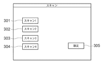
図3は、PC103のPull ScanドライバのUI画面例を示す図である。
FIG. 3 is a diagram illustrating a UI screen example of the Pull Scan driver of the
この画面は、PC103からPull Scanを行う場合にPC103の表示部に表示される画面の例を示す。ボタン301〜304にはそれぞれどのような読み取りを行うかのプロファイルが割り当てられている。ここではこれらプロファイルを「スキャン1」〜「スキャン4」で示している。そしてこれらボタン301〜304のいずれかのボタンが押下されることにより、この複合機101は原稿の読み取りを開始し、PC103に対して読み取った画像データを送信する。こうしてPC103は、その画像データに対して、そのプロファイルに従った処理を実行することになる。
This screen shows an example of a screen displayed on the display unit of the
次に、これらボタン301〜304のそれぞれに具体的にどのような読み取り設定を行えるか図4を参照して説明する。
Next, specific reading settings for each of these
図4は、読み取り設定を行うためのPC103のUI画面例を示す図である。この画面は、ドライバ画面上の「設定」キー305(図3)が押下されることによりPC103の表示部に表示される。401〜404は、図3のボタン301〜304に対応するプロファイルを選択するためのボタンである。図4では、ボタン401が押されて「スキャン1」として設定されているプロファイルが表示された状態を示す。このようにボタン401〜404のいずれかが押されると、そのボタンに対応するプロファイルの設定値が405〜411で示す各フィールドに表示される。尚、これらは設定値は、以前にユーザが入力した設定値か、或いはデフォルトの設定値であり、ユーザはこれらの設定値を所望の値に変更することができる。例えば、405ではプロファイル名(「スキャン1」)を他の名称に変更できる。後ほど説明するが、ここでプロファイル名を変更すると、その変更したプロファイル名が複合機101の表示部135に表示される画面にも反映される。また406では、読み取り時の原稿の種類を選択できる。本実施形態では、選択肢として白黒、白黒(OCR)、グレースケール、カラー、カラー(雑誌、カタログ)が存在するものとする。図4では、カラー原稿の読み取りを指示する「カラー」が選択されて設定されている。407では、JPEG,TIFF,PDF,BMPなど保存する際のファイルの形式を指定する。図4では、JPEGファイル形式を示す「JPEG」が設定されている。408ではスキャンを行う原稿のサイズを指定できる。図4では、A4サイズの原稿を示す「A4」が設定されている。409では、スキャンを行う画像の解像度を指定できる。図4では、300dpiを指示する「300dpi」が設定されている。410では、画像を保存する場所(パス)を指定できる。411では、保存するファイルの名称(ここでは「FileA」)を指定できる。
FIG. 4 is a diagram illustrating an example of a UI screen of the
以上説明した406〜409で示す設定値に基づいて、スキャンして得られた画像データに画像処理を施して所望の画像を得ることになるが、この画像処理は複合機101とPC103のいずれで行ってもよい。本実施形態では、PC103で、この画像処理を行うものとして説明する。尚、疑似Push Scanでは、複合機101側から、Pull Scanのスタート、つまり図3のボタン301〜304のいずれかのボタンを押下させるようにPC103に依頼する。そしてPC103でそのボタンが押されると、PC103から複合機101にスキャンの開始が指示されて、複合機101における画像の読み取りと、その読み取った画像データをPC103に送信する処理が実行される。
Based on the setting values indicated by 406 to 409 described above, the image data obtained by scanning is subjected to image processing to obtain a desired image. This image processing is performed by either the
図5は、本実施形態に係る複合機101とPC103との間の基本的なデータの送受信シーケンスを説明する図である。
FIG. 5 is a diagram for explaining a basic data transmission / reception sequence between the
図において、531は、PC103にPull Scanドライバをインストールするステップを示す。これによりPC103は、Pull Scanを行うことが可能となる。尚、予めPC103にこのドライバがインストールされているときは、この処理は省略できることはいうまでもない。次に532で、PC103から複合機101に対して、PCの名称、プロファイル名、プロファイルの設定内容(パラメタ)を送信する。この処理は、例えば以下のタイミングで実行される。
・PC103にドライバがインストールされたタイミング、或いはPC103が起動されるタイミング
・PC103のドライバのプロファイルの設定が変更されたタイミング
・PC103が、例えばマイクロソフト社のWindows(登録商標)のようにマルチユーザインターフェースを有する場合のログオンユーザ切り替えたタイミング
521は、532で送信される情報を表し、この情報は、PC名、プロファイル名、プロファイルの設定内容を含んでいる。また図3に示すように複数のプロファイルが存在する場合は、これら複数のプログラムファイルが、図3のボタン301〜304で示すプロファイルの数分送信される。以上の処理で、PC103で設定されているプロファイルが複合機101に通知されたことになる。
In the figure,
The timing when the driver is installed on the
511では、複合機101は、PC103から送信された情報を受信し、その情報に含まれるプロファイルの設定内容を複合機101の表示用に再分類する。そして512で、その再分類した項目名を複合機101での項目名に変換する。これは図4に示すPC103のプロファイル設定画面では、文字や注釈を表示するスペースが十分存在することが一般的であり、各項目の詳細を表示して設定を行える方がユーザの利便性が向上する。しかしながら、複合機101の表示部135が、例えば表示できる文字数が少ない場合、むしろ短い文字でプロファイルの属性を表示した方がプロファイルの一覧性が上がり使い勝手が向上する。更に、いくつかの項目の表示をユーザが理解できる範囲内でグルーピングすることも文字数の制限上有効である。従って、511,512で、プロファイルの設定内容を複合機101の表示用に再分類し、その項目名を複合機101で表示する項目名に変換している。これらの処理についての具体的な説明は後述する。
In
次に513で、511,512で処理された、PC名、プロファイル名、再分類項目、変換された項目名を、複合機101に記憶する。これら情報はHDD111に記憶される。次に514で、表示部135に、PC名やプロファイル名やプロファイルの設定内容を表示する。ここでは513で記憶された内容を、表示部135の選択メニューで表示できるようメニュー画面を形成する。このとき複合機101は、表示部135上に図6に示す画面を表示する。尚、この図6の画面については、後ほど複合機101での処理を説明するフローチャートとともに説明する。
Next, in 513, the PC name, profile name, reclassification item, and converted item name processed in 511 and 512 are stored in the multi-function peripheral 101. Such information is stored in the
515では、ユーザは、表示部135に表示したプロファイル(図6)を選択し、複合機101からPull ScanをPC103に依頼する。522では、PC103に対するPull Scan指示と、515で選択されたプロファイルが送信される。これにより533で、PC103は、複合機101からのPull Scan開始要求を受け取ってPull Scanの処理に進む。ここではPC103は、522で伝達された内容に基づき、図3の301〜304のいずれのプロファイルによるPull Scanを開始するかを判断する。523では、PC103から複合機101に対してスキャン開始指示を通知する。これにより516で、複合機101は、523で指示された内容に基づいて原稿を読み取って、その画像データを取得する。そして524で、516で読み取った画像データをPC103に送信する。これによりPC103は、524で送信された画像データを受信し、522で送信されたプロファイルのパラメタに基づいて画像処理を行う。また、本実施形態では保存先として、PC103のハードディスク上のフォルダが、図4の410,411で指定されている。このため、535では、その画像処理された画像データを、図4の画面で指示されたフォルダに格納する。
In 515, the user selects the profile (FIG. 6) displayed on the
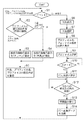
図7は、本実施形態に係る複合機101における処理手順を説明するフローチャートである。尚、この処理を実行するプログラムはROM95に格納されており、CPU180の制御の下に実行される。
FIG. 7 is a flowchart for explaining a processing procedure in the multifunction peripheral 101 according to the present embodiment. Note that a program for executing this processing is stored in the
まずS1で、CPU180は、PC103からの情報(PC名+プロファイル名+プロファイルの設定内容)(図5の521)の受信か、ユーザにより操作が行われたことによるイベントの発生かどうかを判断する。PC103からの情報の受信の場合はS2に進み、CPU180は、S1で受信したプロファイルの設定内容から、読み取り対象の原稿の種類を判別する。原稿の種類は図4の406で設定されている。ここでPC103から受信するプロファイルは、複数存在しても良い。尚、本実施形態では、プロファイルの設定内容として原稿の種類の情報のみを複合機101の表示部135に表示するものとする。よってS2では原稿の種類のみを判別し、原稿の種類が白黒、白黒(OCR)、グレースケールの場合はS4に進み、カラー、カラー(雑誌、カタログ)の場合はS3に進む。S3では、CPU180は、PC名とプロファイル名と、プロファイルの設定内容に基づいて表示部135に表示する文字列を生成する。ここで、原稿の種類がカラー、カラー(雑誌、カタログ)の場合は「カラー」という文字列にする。一方、S4でCPU180は、PC名とプロファイル名と、プロファイルの設定内容に基づいて表示部135に表示する文字列を生成する。ここでは、原稿の種類が白黒、白黒(OCR)、グレースケールの場合は「白黒」という文字列にする。尚、S3或いはS4で生成された文字列は、PC103での表示内容と異なっているが、PC名とプロファイル名と、プロファイルの設定内容を少なくとも識別できる文字列である。こうしてS3或いはS4を実行するとS5に進み、CPU180は、S3或いはS4で作成した文字列をHDD111に記憶する。そしてS1の処理に進む。
First, in step S1, the
一方、S1でユーザの操作であると判断したときはS6に進み、これ以降CPU180は、操作部150から疑似Push Scanのメニューが選択された場合の処理を行う。まずS6で、S5で記憶したPC名を表示する。
On the other hand, when it is determined in S1 that the operation is a user operation, the process proceeds to S6, and thereafter, the
図6は、実施形態に係る複合機101で表示されるスキャン機能選択画面、PCの選択画面の一例を示す図である。 FIG. 6 is a diagram illustrating an example of a scan function selection screen and a PC selection screen displayed on the multifunction peripheral 101 according to the embodiment.
図6において、スキャン機能選択画面601で、602で示すようにPCが選択されると、更にそのPCを選択する選択画面610が表示される。このPC選択画面610には、S3或いはS4で作成されたPC名の文字列に従った文字列が表示され、選択肢(PC名)として表示される。図6の例では、3つのPCの名称「Host1」「Host2」「Host3」が表示されている。次にS7に進み、CPU180は、操作部150のハードキーの入力を検知してどのPCが選択されたかを認識する。図6では611で示す「Host1」(PC103に相当)が選択されたものとする。次にS8に進み、CPU180が、その選択されたPC103が持つプロファイル名を表示する。
In FIG. 6, when a PC is selected on the scan
図6で説明すると、PC選択画面610で、611で示すPC「Host1」が選択され、そのPC103のプロファイル選択画面620が表示されている。そして、このプロファイル選択画面620には、S3或いはS4で生成された文字列(プロファイル名とプロファイルの設定内容)が表示される。またS3で生成された文字列は、図6の621のように「カラー」と共に「スキャン−1」として表示される。またS4で生成された文字列は、図6の622のように「白黒」と共に「スキャン−2」として表示される。そしてS9に進み、CPU180は、操作部150のハードキーの入力を検知して、どのプロファイルが選択されたかの情報を得る。複合機101では、PCで設定されたプロファイルの設定内容を複合機101の表示用に「カラー」と「白黒」に再分類し、その項目名を複合機101で表示する項目名(「カラー スキャン−1」「「白黒 スキャン−2」」など)に変換して表示している。
Referring to FIG. 6, the PC “Host1” indicated by 611 is selected on the
そしてS10で、CPU180は操作部150のスタートキーが押されたかどうかを判定し、スタートキーが押されるとS11に進む。S11で、CPU180は、自機にPull Scanを行わせるように、S7で選択されたPC(「Host1」、即ち、PC103とする)に送信依頼要求を発行する。その際に、PC103上のドライバが持つどのプロファイルでPull Scanを行うかの情報も送信する。そしてS12で、CPU180は、PC103から発行されるPull Scan指示(画像送信要求)を受信するのを待つ。このPull Scan指示を受信するとS13に進み、CPU180はリーダ部13を制御して原稿をスキャンし、その原稿の画像データを得る(図5の516)。そしてS14でCPU180は、図5の524で示すように、PC103にその画像データを送信する。
In step S10, the
<PCの処理説明>
図8は、本実施形態に係るPC103における処理手順を示すフローチャートである。尚、この処理を実行するプログラムはPC103のHDD(不図示)にインストールされており、実行時にメモリメモリ(不図示)にロードされ、CPU(不図示)の制御の下に実行される。
<Description of PC processing>
FIG. 8 is a flowchart showing a processing procedure in the
まずS21で、PC103にPull Scanのドライバをインストールする。このS21は、一度インストールを行えば明示的に消去されない限り二度と必要ないため、省略可能である。次にS22に進み、PC103は、各種イベントの発生を待つ。ここでは待つイベントの種類は以下の通りである。
・PC103が起動された、又は、ログオンユーザが変更された
・Pull Scanドライバのプロファイルの設定、或いは変更が要求された
・複合機101からPull Scanをするよう促された(通知された)
このS22で、Pull Scanドライバのプロファイルの設定或いは変更が要求された場合はS23に進む。S23では、PC103は、ユーザにより設定された、或いは変更された図4の405〜411で設定された情報を記憶する。そしてS24に進み、PC103は、複合機101で疑似Push Scan時に表示するメニュー(図6)を作成させるために、PC名とプロファイル名とプロファイルの設定内容を複合機101に送信する(図5の521に相当)。
In step S21, a Pull Scan driver is installed in the
-The
If it is determined in S22 that the setting or change of the profile of the Pull Scan driver is requested, the process proceeds to S23. In S23, the
一方、S22でPC103が起動されたか、又は、ログオンユーザが変更された場合はS24に進む。これは、PC103の持つプロファイルの情報を複合機101に通知して疑似Push Scan時に表示するメニュー(図6)を作成させるための処理である。
On the other hand, if the
一方、S22で、複合機からPull Scanをするよう促された(通知された)場合はS25に進む。S25では、PC103は、複合機101からPull Scan開始の依頼と、Pull Scanを行う場合の選択プロファイル情報を受信する(図5の522に相当)。そしてPC103は、S22で受信した情報に基づいて、プロファイル301〜304(図3)の中から、複合機101で選択されたプロファイルに対応するプロファイルを選択する。次にS26に進み、PC103は、S25で行った設定に基づいて複合機101に対してPull Scanのスキャン指示を送信する(図5の523)。そして複合機101から画像データを送信されるのを待つ。S27で画像データを受信するとS28に進み、PC103は、複合機101から画像データを受信する。そしてS29に進み、PC103は、S25で複合機101から受信したPull Scanを行う場合のプロファイルの設定に基づいて画像処理を行う。そしてS30に進み、PC103は、複合機101で選択されたプロファイル情報に対応するプロファイルの画像データの格納場所(図4の410)、ファイル名(図4の411)を参照して、その設定された場所にそのファイル名を付して画像データを格納する。
On the other hand, when it is urged (notified) to perform a pull scan from the multifunction machine in S22, the process proceeds to S25. In S <b> 25, the
尚、本実施形態では、ネットワーク(TCP/IP)を通信手段として使用しているが、USBを始めとするその他の通信手段でも同様の処理が適用できる。 In this embodiment, the network (TCP / IP) is used as a communication means, but the same processing can be applied to other communication means such as USB.
また本実施形態では、複合機101の表示部135で表示するプロファイルの設定内容として原稿の種類の例を提示したが、その他のパラメタでも同様の処理が行えることは言うまでもない。例えばファイルの種類(JPEG,PDF等)や原稿サイズ(A4,A3等)や解像度であってもよいし、これらの複数であってもよい。また、どのパラメタを表示部135に表示させるのか、即ち表示対象パラメタをPull scanドライバの画面(図4)上でユーザが選択できるようにしてもよい。
In this embodiment, the example of the type of document is presented as the setting contents of the profile displayed on the
また本実施形態では、複合機101の表示部135で表示するプロファイルの設定内容として「カラー」、「白黒」という文字列の例を提示したが、表示部135の能力が許せばグラフィカルなアイコンで表示しても良い。
In this embodiment, examples of character strings of “color” and “black and white” are presented as the setting contents of the profile displayed on the
(他の実施形態)
本発明は、以下の処理を実行することによっても実現される。即ち、上述した実施形態の機能を実現するソフトウェア(プログラム)をネットワーク又は各種記憶媒体を介してシステム或いは装置に供給し、そのシステム或いは装置のコンピュータ(又はCPUやMPU等)がプログラムコードを読み出して実行する処理である。この場合、そのプログラム、及び該プログラムを記憶した記憶媒体は本発明を構成することになる。
(Other embodiments)
The present invention is also realized by executing the following processing. That is, software (program) that realizes the functions of the above-described embodiments is supplied to a system or apparatus via a network or various storage media, and a computer (or CPU, MPU, etc.) of the system or apparatus reads the program code. It is a process to be executed. In this case, the program and the storage medium storing the program constitute the present invention.
以上説明したように本実施形態によれば、MFPのUIでプロファイルを選択する時に、プロファイル名と共にプロファイルの設定内容も表示される。このため、ユーザが出力画像の形式をデバイスの前で確認することができ、PCに戻って初めてスキャン結果の間違いに気付くことが防止され、利便性が高まる。 As described above, according to the present embodiment , when a profile is selected on the UI of the MFP, the setting contents of the profile are displayed together with the profile name. For this reason, the user can confirm the format of the output image in front of the device, and the user is prevented from noticing an error in the scan result only after returning to the PC, thereby improving convenience.
また廉価なMFPのUIはPCの画像パラメタ設定画面と異なり制約が多く、長い文字列が表示できない、又はグラフィカルなアイコンが使用できないことが多い。これに対して本実施形態によれば、プロファイルの設定内容表示をPCとMFPとで変えることにより、MFPではMFPに適した表示が行われ、ユーザへのプロファイル認識性が高まり、間違いがより低減できるという効果がある。 In addition, the UI of an inexpensive MFP has many restrictions unlike the image parameter setting screen of a PC, and often a long character string cannot be displayed or a graphical icon cannot be used. On the other hand, according to the present embodiment, by changing the setting content display of the profile between the PC and the MFP, the MFP performs a display suitable for the MFP, enhances the profile recognizability to the user, and further reduces errors. There is an effect that can be done.
Claims (10)
原稿を読み取って当該原稿の画像データを生成する読み取り手段と、
前記読み取り手段により画像データを生成するための設定を含むプロファイルを、前記情報機器から取得する取得手段と、
前記取得手段により取得した前記プロファイルの設定内容を前記画像読取装置の表示用に分類し、前記分類された設定内容に基づいて生成された項目を前記画像読取装置の表示部に表示させる表示制御手段と、
前記表示制御手段により前記表示部に表示された前記項目が選択された場合、当該選択された項目に対応するプロファイルの情報を前記情報機器に送信する送信手段と、
前記情報機器から送信される原稿読み取り指示に応じて、前記読み取り手段により生成した前記画像データを前記情報機器に送信する画像送信手段と、
を有することを特徴とする画像読取装置。 An image reading apparatus capable of communicating with an information device,
Reading means for reading a document and generating image data of the document;
An acquisition means for acquiring a profile including a setting for generating image data by the reading means from the information device;
The Ruishi minute settings of the profile acquired by the acquisition unit for display of the image reading apparatus, the display control to display the item which is generated based on the classified settings to the display unit of the image reading apparatus Means,
When the item displayed on the display unit is selected by the display control unit, a transmission unit that transmits information on a profile corresponding to the selected item to the information device;
An image transmission unit that transmits the image data generated by the reading unit to the information device in response to a document reading instruction transmitted from the information device;
An image reading apparatus comprising:
原稿を読み取って画像データを生成するための設定を含むプロファイルを前記情報機器から取得する取得工程と、
前記取得工程で取得した前記プロファイルの設定内容を前記画像読取装置の表示用に分類し、前記分類された設定内容に基づいて生成された項目を前記画像読取装置の表示部に表示させる表示制御工程と、
前記表示制御工程で前記表示部に表示された前記項目が選択された場合、当該選択された項目に対応するプロファイルの情報を前記情報機器に送信する送信工程と、
前記情報機器から送信される原稿読み取り指示に応じて、原稿を読み取って生成した前記画像データを前記情報機器に送信する画像送信工程と、
を有することを特徴とする画像読取装置の制御方法。 An image reading apparatus control method capable of communicating with an information device,
An acquisition step of acquiring from the information device a profile including settings for reading a document and generating image data ;
Display for displaying Ruishi minute settings of the profile obtained in the previous SL acquisition step for display of the image reading apparatus, an item that has been generated based on the classified settings to the display unit of the image reading apparatus Control process;
If the items displayed on the display unit in front Symbol display control step is selected, a transmission step of transmitting profile information corresponding to the selected item to the information apparatus,
Depending on the original reading instruction sent from the previous SL information apparatus, an image transmission step of transmitting the image data generated by reading a document in the information equipment,
An image reading apparatus control method comprising:
Priority Applications (2)
| Application Number | Priority Date | Filing Date | Title |
|---|---|---|---|
| JP2009149181A JP5500883B2 (en) | 2009-06-23 | 2009-06-23 | Image reading apparatus, control method therefor, and program therefor |
| US12/782,149 US8482773B2 (en) | 2009-06-23 | 2010-05-18 | Image reading apparatus and method of controlling the apparatus, and storage medium |
Applications Claiming Priority (1)
| Application Number | Priority Date | Filing Date | Title |
|---|---|---|---|
| JP2009149181A JP5500883B2 (en) | 2009-06-23 | 2009-06-23 | Image reading apparatus, control method therefor, and program therefor |
Publications (3)
| Publication Number | Publication Date |
|---|---|
| JP2011009880A JP2011009880A (en) | 2011-01-13 |
| JP2011009880A5 JP2011009880A5 (en) | 2012-08-09 |
| JP5500883B2 true JP5500883B2 (en) | 2014-05-21 |
Family
ID=43354089
Family Applications (1)
| Application Number | Title | Priority Date | Filing Date |
|---|---|---|---|
| JP2009149181A Expired - Fee Related JP5500883B2 (en) | 2009-06-23 | 2009-06-23 | Image reading apparatus, control method therefor, and program therefor |
Country Status (2)
| Country | Link |
|---|---|
| US (1) | US8482773B2 (en) |
| JP (1) | JP5500883B2 (en) |
Families Citing this family (4)
| Publication number | Priority date | Publication date | Assignee | Title |
|---|---|---|---|---|
| JP6230453B2 (en) * | 2014-03-17 | 2017-11-15 | キヤノン株式会社 | Imaging apparatus and control method thereof |
| KR20180041402A (en) * | 2016-10-14 | 2018-04-24 | 에스프린팅솔루션 주식회사 | Image scanning apparatus and method for controlling scan |
| JP6852509B2 (en) * | 2017-03-30 | 2021-03-31 | ブラザー工業株式会社 | Programs and information processing equipment |
| JP6879131B2 (en) * | 2017-08-31 | 2021-06-02 | ブラザー工業株式会社 | Scan system, information processing device, and scanner driver |
Family Cites Families (10)
| Publication number | Priority date | Publication date | Assignee | Title |
|---|---|---|---|---|
| US6459499B1 (en) * | 1998-12-22 | 2002-10-01 | Canon Kabushiki Kaisha | Push technology for network scanner |
| US7139094B2 (en) * | 2000-12-28 | 2006-11-21 | Xerox Corporation | Systems and methods for simplified scanning using multi-function devices |
| JP2003259074A (en) * | 2002-03-01 | 2003-09-12 | Kyocera Mita Corp | Image processing apparatus, image processing content setting program, and image processing system |
| JP3960177B2 (en) * | 2002-09-13 | 2007-08-15 | 富士ゼロックス株式会社 | Parameter setting apparatus and method |
| JP2004222016A (en) * | 2003-01-16 | 2004-08-05 | Sharp Corp | Scanner repeater and method for controlling read of picture |
| JP2005244754A (en) | 2004-02-27 | 2005-09-08 | Seiko Epson Corp | Image data generating/utilizing system |
| JP4539293B2 (en) * | 2004-11-01 | 2010-09-08 | 富士ゼロックス株式会社 | Document processing system, document processing apparatus, device, UI display processing method and display processing program for document processing system |
| JP2007118374A (en) * | 2005-10-27 | 2007-05-17 | Sharp Corp | Printing setting device |
| US20070183002A1 (en) * | 2006-02-07 | 2007-08-09 | Fatima Corona | System and method for user selectable scan settings on a scan capable device |
| US7843586B2 (en) * | 2006-09-28 | 2010-11-30 | Sharp Laboratories Of America, Inc. | Systems and methods for facilitating direct scanning to network destinations by clients |
-
2009
- 2009-06-23 JP JP2009149181A patent/JP5500883B2/en not_active Expired - Fee Related
-
2010
- 2010-05-18 US US12/782,149 patent/US8482773B2/en not_active Expired - Fee Related
Also Published As
| Publication number | Publication date |
|---|---|
| JP2011009880A (en) | 2011-01-13 |
| US8482773B2 (en) | 2013-07-09 |
| US20100321728A1 (en) | 2010-12-23 |
Similar Documents
| Publication | Publication Date | Title |
|---|---|---|
| EP2216979B1 (en) | Image processing apparatus, information processing system, method of controlling the same | |
| JP5377039B2 (en) | Image processing apparatus, image processing apparatus control method, and program | |
| JP5669571B2 (en) | Image reading apparatus, control method thereof, and control program | |
| US8922816B2 (en) | Information processing apparatus, control method thereof, and storage medium storing program | |
| JP5735763B2 (en) | Image reading apparatus, control method therefor, and computer program | |
| EP2575343B1 (en) | Image reading apparatus and image reading system | |
| US8508774B2 (en) | Image processing apparatus, method for controlling image processing apparatus, and recording medium | |
| US9185242B2 (en) | Image reading apparatus, information processing apparatus, control method thereof, and storage medium | |
| JP5500883B2 (en) | Image reading apparatus, control method therefor, and program therefor | |
| JP6412353B2 (en) | Image reading apparatus, control method therefor, program, and system | |
| JP2008065534A (en) | Information processing system and server | |
| KR20050075229A (en) | Multi function peripheral and a method operation controlling thereof | |
| US20110096363A1 (en) | Image processing apparatus | |
| JP5460907B2 (en) | Image processing apparatus, image processing apparatus control method, and program | |
| JP5725844B2 (en) | Image reading apparatus, image reading apparatus control method, and program | |
| JP2006085255A (en) | Image processor, image processing system, method for processing setting, storage medium for storing computer-readable program, and program | |
| JP4641488B2 (en) | Image forming apparatus | |
| JP2006054671A (en) | Digital multi-function machine | |
| JP2006100925A (en) | Image forming apparatus and image processing system | |
| JP2009159213A (en) | Image processing apparatus, terminal device and scan data transfer system | |
| JP2009200539A (en) | Image processing apparatus |
Legal Events
| Date | Code | Title | Description |
|---|---|---|---|
| A521 | Written amendment |
Free format text: JAPANESE INTERMEDIATE CODE: A523 Effective date: 20120621 |
|
| A621 | Written request for application examination |
Free format text: JAPANESE INTERMEDIATE CODE: A621 Effective date: 20120621 |
|
| A977 | Report on retrieval |
Free format text: JAPANESE INTERMEDIATE CODE: A971007 Effective date: 20130711 |
|
| A131 | Notification of reasons for refusal |
Free format text: JAPANESE INTERMEDIATE CODE: A131 Effective date: 20130719 |
|
| A521 | Written amendment |
Free format text: JAPANESE INTERMEDIATE CODE: A523 Effective date: 20130913 |
|
| TRDD | Decision of grant or rejection written | ||
| A01 | Written decision to grant a patent or to grant a registration (utility model) |
Free format text: JAPANESE INTERMEDIATE CODE: A01 Effective date: 20140210 |
|
| A61 | First payment of annual fees (during grant procedure) |
Free format text: JAPANESE INTERMEDIATE CODE: A61 Effective date: 20140311 |
|
| LAPS | Cancellation because of no payment of annual fees |