JP5497150B2 - Extraction with internal filter in the tandem rotor of the compressor - Google Patents
Extraction with internal filter in the tandem rotor of the compressor Download PDFInfo
- Publication number
- JP5497150B2 JP5497150B2 JP2012504049A JP2012504049A JP5497150B2 JP 5497150 B2 JP5497150 B2 JP 5497150B2 JP 2012504049 A JP2012504049 A JP 2012504049A JP 2012504049 A JP2012504049 A JP 2012504049A JP 5497150 B2 JP5497150 B2 JP 5497150B2
- Authority
- JP
- Japan
- Prior art keywords
- compressor
- orifice
- rotor
- secondary air
- gas
- Prior art date
- Legal status (The legal status is an assumption and is not a legal conclusion. Google has not performed a legal analysis and makes no representation as to the accuracy of the status listed.)
- Expired - Fee Related
Links
Images


Classifications
-
- F—MECHANICAL ENGINEERING; LIGHTING; HEATING; WEAPONS; BLASTING
- F04—POSITIVE - DISPLACEMENT MACHINES FOR LIQUIDS; PUMPS FOR LIQUIDS OR ELASTIC FLUIDS
- F04D—NON-POSITIVE-DISPLACEMENT PUMPS
- F04D29/00—Details, component parts, or accessories
- F04D29/26—Rotors specially for elastic fluids
- F04D29/28—Rotors specially for elastic fluids for centrifugal or helico-centrifugal pumps for radial-flow or helico-centrifugal pumps
- F04D29/284—Rotors specially for elastic fluids for centrifugal or helico-centrifugal pumps for radial-flow or helico-centrifugal pumps for compressors
-
- B—PERFORMING OPERATIONS; TRANSPORTING
- B64—AIRCRAFT; AVIATION; COSMONAUTICS
- B64D—EQUIPMENT FOR FITTING IN OR TO AIRCRAFT; FLIGHT SUITS; PARACHUTES; ARRANGEMENTS OR MOUNTING OF POWER PLANTS OR PROPULSION TRANSMISSIONS IN AIRCRAFT
- B64D27/00—Arrangement or mounting of power plant in aircraft; Aircraft characterised thereby
- B64D27/02—Aircraft characterised by the type or position of power plant
- B64D27/10—Aircraft characterised by the type or position of power plant of gas-turbine type
-
- F—MECHANICAL ENGINEERING; LIGHTING; HEATING; WEAPONS; BLASTING
- F01—MACHINES OR ENGINES IN GENERAL; ENGINE PLANTS IN GENERAL; STEAM ENGINES
- F01D—NON-POSITIVE DISPLACEMENT MACHINES OR ENGINES, e.g. STEAM TURBINES
- F01D25/00—Component parts, details, or accessories, not provided for in, or of interest apart from, other groups
- F01D25/08—Cooling; Heating; Heat-insulation
-
- F—MECHANICAL ENGINEERING; LIGHTING; HEATING; WEAPONS; BLASTING
- F02—COMBUSTION ENGINES; HOT-GAS OR COMBUSTION-PRODUCT ENGINE PLANTS
- F02C—GAS-TURBINE PLANTS; AIR INTAKES FOR JET-PROPULSION PLANTS; CONTROLLING FUEL SUPPLY IN AIR-BREATHING JET-PROPULSION PLANTS
- F02C7/00—Features, components parts, details or accessories, not provided for in, or of interest apart form groups F02C1/00 - F02C6/00; Air intakes for jet-propulsion plants
- F02C7/12—Cooling of plants
- F02C7/16—Cooling of plants characterised by cooling medium
- F02C7/18—Cooling of plants characterised by cooling medium the medium being gaseous, e.g. air
-
- F—MECHANICAL ENGINEERING; LIGHTING; HEATING; WEAPONS; BLASTING
- F04—POSITIVE - DISPLACEMENT MACHINES FOR LIQUIDS; PUMPS FOR LIQUIDS OR ELASTIC FLUIDS
- F04D—NON-POSITIVE-DISPLACEMENT PUMPS
- F04D29/00—Details, component parts, or accessories
- F04D29/26—Rotors specially for elastic fluids
- F04D29/28—Rotors specially for elastic fluids for centrifugal or helico-centrifugal pumps for radial-flow or helico-centrifugal pumps
-
- F—MECHANICAL ENGINEERING; LIGHTING; HEATING; WEAPONS; BLASTING
- F04—POSITIVE - DISPLACEMENT MACHINES FOR LIQUIDS; PUMPS FOR LIQUIDS OR ELASTIC FLUIDS
- F04D—NON-POSITIVE-DISPLACEMENT PUMPS
- F04D29/00—Details, component parts, or accessories
- F04D29/58—Cooling; Heating; Diminishing heat transfer
-
- F—MECHANICAL ENGINEERING; LIGHTING; HEATING; WEAPONS; BLASTING
- F04—POSITIVE - DISPLACEMENT MACHINES FOR LIQUIDS; PUMPS FOR LIQUIDS OR ELASTIC FLUIDS
- F04D—NON-POSITIVE-DISPLACEMENT PUMPS
- F04D29/00—Details, component parts, or accessories
- F04D29/66—Combating cavitation, whirls, noise, vibration or the like; Balancing
- F04D29/68—Combating cavitation, whirls, noise, vibration or the like; Balancing by influencing boundary layers
- F04D29/681—Combating cavitation, whirls, noise, vibration or the like; Balancing by influencing boundary layers especially adapted for elastic fluid pumps
- F04D29/682—Combating cavitation, whirls, noise, vibration or the like; Balancing by influencing boundary layers especially adapted for elastic fluid pumps by fluid extraction
-
- Y—GENERAL TAGGING OF NEW TECHNOLOGICAL DEVELOPMENTS; GENERAL TAGGING OF CROSS-SECTIONAL TECHNOLOGIES SPANNING OVER SEVERAL SECTIONS OF THE IPC; TECHNICAL SUBJECTS COVERED BY FORMER USPC CROSS-REFERENCE ART COLLECTIONS [XRACs] AND DIGESTS
- Y02—TECHNOLOGIES OR APPLICATIONS FOR MITIGATION OR ADAPTATION AGAINST CLIMATE CHANGE
- Y02T—CLIMATE CHANGE MITIGATION TECHNOLOGIES RELATED TO TRANSPORTATION
- Y02T50/00—Aeronautics or air transport
- Y02T50/60—Efficient propulsion technologies, e.g. for aircraft
Landscapes
- Engineering & Computer Science (AREA)
- Mechanical Engineering (AREA)
- General Engineering & Computer Science (AREA)
- Chemical & Material Sciences (AREA)
- Combustion & Propulsion (AREA)
- Aviation & Aerospace Engineering (AREA)
- Physics & Mathematics (AREA)
- Thermal Sciences (AREA)
- Structures Of Non-Positive Displacement Pumps (AREA)
Description
本発明は、遠心または混流圧縮機用の2次空気システム、および特に航空機ガスタービンの遠心または混流圧縮機用の2次空気システムの技術分野に関する。 The present invention relates to the technical field of secondary air systems for centrifugal or mixed flow compressors, and in particular secondary air systems for centrifugal or mixed flow compressors of aircraft gas turbines.
従来の方法では、ガスタービンは、酸化剤ガス、通常は空気を吸い込み、酸化剤ガスを圧縮する圧縮システムの入口に酸化剤ガスを運ぶように設計される空気入口から構成されている。圧縮システムは、混合または遠心タイプのうちの少なくとも1つの圧縮機から構成され、各遠心タイプの圧縮機は、伝動シャフトに取り付けられる少なくとも1つのロータ、および少なくとも1つのステータを含む。圧縮システムによって圧縮される酸化剤ガスは、燃料と混合され、燃焼室内で燃焼される。伝動シャフトに取り付けられる少なくとも1つのタービンは、燃焼室で燃焼されるガスの運動エネルギーのほんの一部分を、少なくとも圧縮機を駆動する働きをする機械エネルギーに変換する。既燃ガスは、高温部品、たとえばタービンと熱を交換し、その結果、既燃ガスは、高温部品の温度上昇を制限するために冷却するのに適している。 In a conventional manner, a gas turbine consists of an air inlet that is designed to draw oxidant gas, usually air, and carry the oxidant gas to the inlet of a compression system that compresses the oxidant gas. The compression system is comprised of at least one compressor of a mixing or centrifugal type, each centrifugal type compressor including at least one rotor attached to a transmission shaft and at least one stator. The oxidant gas compressed by the compression system is mixed with fuel and burned in the combustion chamber. At least one turbine attached to the transmission shaft converts only a fraction of the kinetic energy of the gas combusted in the combustion chamber into mechanical energy that serves to drive at least the compressor. The burnt gas exchanges heat with a hot part, such as a turbine, so that the burned gas is suitable for cooling to limit the temperature rise of the hot part.
少なくとも1つの遠心または混流圧縮機を含むタイプのガスタービンでは、前記遠心または混流圧縮機のステータから酸化剤ガスを抽気するように構成される2次空気システムを使って、この冷却を実現することが知られている。抽気は、通常、流体の流れに対して接線方向に配置される複数の抽気オリフィスによって行われる。 In a gas turbine of the type that includes at least one centrifugal or mixed flow compressor, this cooling is achieved using a secondary air system configured to bleed oxidant gas from the stator of the centrifugal or mixed flow compressor. It has been known. The bleed is usually performed by a plurality of bleed orifices arranged tangentially to the fluid flow.
それにもかかわらず、酸化剤ガスは、少なくとも部分的に前記抽気オリフィスを詰まらせるように働く汚染粒子を含む場合がある。この目詰まり現象は、2次空気システムによって抽気されるガスの量の著しい減少をもたらし、その結果として、高温部品の温度の上昇を招き、それにより、高温部品の寿命および/または機械的強度の低下を生じさせる。 Nevertheless, the oxidant gas may contain contaminating particles that serve to at least partially clog the bleed orifice. This clogging phenomenon results in a significant decrease in the amount of gas extracted by the secondary air system, resulting in an increase in the temperature of the hot part, thereby increasing the life and / or mechanical strength of the hot part. Cause a drop.
さらに、遠心または混流圧縮機の全体的な効率は、圧縮機のロータに沿った酸化剤ガスの流れの攪乱によって、たとえば、剥離されるようになるロータと接触している酸化剤ガスの境界層によって低下され得る。 Further, the overall efficiency of a centrifugal or mixed flow compressor is due to disturbances in the flow of oxidant gas along the compressor rotor, for example, the boundary layer of oxidant gas in contact with the rotor becoming exfoliated. Can be lowered.
本発明の第1の目的は、酸化剤ガスの汚染に対して頑健な2次空気システムを提供することである。 A primary object of the present invention is to provide a secondary air system that is robust against oxidant gas contamination.
本発明の第2の目的は、遠心または混流圧縮機内の空気の流れを改善することができる2次空気システムを提供することである。 It is a second object of the present invention to provide a secondary air system that can improve the air flow in a centrifugal or mixed flow compressor.
上記の2つの技術的問題のうちの少なくとも1つを解決するために、本発明の2次空気システムは、酸化剤ガスを圧縮するように構成される遠心または混流圧縮機に組み込まれるように設計され、前記遠心または混流圧縮機は、回転軸を有するロータを含んでいる。 To solve at least one of the above two technical problems, the secondary air system of the present invention is designed to be incorporated into a centrifugal or mixed flow compressor configured to compress oxidant gas. The centrifugal or mixed flow compressor includes a rotor having a rotating shaft.
本発明の2次空気システムは、圧縮機のロータに配置される酸化剤ガス抽気システムを備えることが有利である。これにより、酸化剤ガスに含まれることもある汚染粒子に遠心力を作用させることができるようになり、それによって、前記汚染粒子による抽気システムの目詰まりの進行を防止し、または少なくとも制限する。 The secondary air system of the present invention advantageously comprises an oxidant gas bleed system located in the compressor rotor. This allows centrifugal force to act on the contaminating particles that may be contained in the oxidant gas, thereby preventing or at least limiting the progression of clogging of the bleed system by the contaminating particles.
さらに、本発明の2次空気システムは、ロータに沿った酸化剤ガスの流れを改善することによって、圧縮機の空気力学を改善する。 Furthermore, the secondary air system of the present invention improves compressor aerodynamics by improving the flow of oxidant gas along the rotor.
好ましい実施形態では、2次空気システムは、少なくとも圧縮ガスを燃焼するように構成される燃焼室を含み、かつ高温の既燃ガスと接触する少なくとも1つの高温部品を有するタイプのガスタービンの圧縮機に組み込まれるように設計される。この変形では、2次空気システムはまた、高温部品の温度を低下させるために、高温部品のうちの少なくとも1つに抽気ガスを導くためのチャネリングシステムも含んでいる。 In a preferred embodiment, the secondary air system includes a combustion chamber configured to combust at least compressed gas and has at least one hot component in contact with the hot burned gas, the compressor of a gas turbine of the type Designed to be incorporated into. In this variation, the secondary air system also includes a channeling system for directing the bleed gas to at least one of the hot components to reduce the temperature of the hot components.
好ましい実施形態では、2次空気システムは、外表面を有する圧縮機に組み込まれるように設計される。この実施形態では、チャネリングシステムは、ロータ内側に少なくとも1つのキャビティを含み、一方で抽気システムは、ロータに作られる少なくとも1つのオリフィスを含む。各オリフィスは、外表面から延在し、少なくとも1つのキャビティに通じ、オリフィス軸線を有する。 In a preferred embodiment, the secondary air system is designed to be incorporated into a compressor having an outer surface. In this embodiment, the channeling system includes at least one cavity inside the rotor, while the bleed system includes at least one orifice made in the rotor. Each orifice extends from the outer surface and communicates with at least one cavity and has an orifice axis.
また、本発明の2次空気システムは、以下の有利な特徴のうちの少なくとも1つを含むこともでき、
2次空気システムは、少なくとも1つのタービンを含むタイプのガスタービンの圧縮機に組み込まれるように設計され、
チャネリングシステムは、抽気ガスをタービンに送出する働きをし、
ロータは、ハブを有し、オリフィスのうちの少なくとも1つは、ハブに作られ、
2次空気システムは、複数の主ブレードおよび/または複数の中間ブレードを備えるロータを有する圧縮機に取り付けられるように設計され、
各主ブレードには、主前縁が設けられ、
各中間ブレードには、中間前縁が設けられ、
少なくとも1つのオリフィスの少なくとも一部は、主前縁と中間前縁との間に回転軸に関して軸方向に配置され、
少なくとも1つのオリフィスの少なくとも一部は、回転軸に対して軸方向に、および中間前縁の後の酸化剤ガスの流れ方向に配置され、
少なくとも1つのオリフィスの少なくとも一部は、主ブレードの前縁の前に回転軸に対して軸方向に配置され、
主または中間タイプの各ブレードは、負圧側面を含み、
少なくとも1つのオリフィスの少なくとも一部は、負圧側面のうちの1つの付近に回転軸に対して半径方向に配置される。
The secondary air system of the present invention may also include at least one of the following advantageous features:
The secondary air system is designed to be incorporated into a compressor of a gas turbine of a type that includes at least one turbine;
The channeling system serves to deliver bleed gas to the turbine,
The rotor has a hub and at least one of the orifices is made in the hub;
The secondary air system is designed to be attached to a compressor having a rotor with multiple primary blades and / or multiple intermediate blades;
Each main blade is provided with a main leading edge,
Each intermediate blade is provided with an intermediate leading edge,
At least a portion of the at least one orifice is disposed axially with respect to the axis of rotation between the main leading edge and the intermediate leading edge;
At least a portion of the at least one orifice is disposed axially relative to the axis of rotation and in the direction of oxidant gas flow after the intermediate leading edge;
At least a portion of the at least one orifice is disposed axially relative to the axis of rotation before the leading edge of the main blade;
Each blade of the main or intermediate type includes a suction side,
At least a portion of the at least one orifice is disposed radially about the axis of rotation near one of the suction sides.
本発明の第3の目的は、酸化剤ガスの汚染に対して頑健な圧縮機ロータを提供することである。 A third object of the present invention is to provide a compressor rotor that is robust against oxidant gas contamination.
このために、本発明の圧縮機ロータは、上で規定した通りの2次空気システムを含む。 For this purpose, the compressor rotor according to the invention comprises a secondary air system as defined above.
本発明の第4の目的は、酸化剤ガスの汚染に対して頑健な圧縮機を提供することである。 A fourth object of the present invention is to provide a compressor that is robust against oxidant gas contamination.
このために、本発明の圧縮機は、上で規定した通りのロータを含む。 For this purpose, the compressor according to the invention comprises a rotor as defined above.
本発明の第5の目的は、酸化剤ガスの汚染に対して頑健なガスタービンを提供することである。 A fifth object of the present invention is to provide a gas turbine that is robust against oxidant gas contamination.
本発明の第6の目的は、圧縮機の回転速度に応じて抽気ガス流量を最適化する可能性を提供することである。 The sixth object of the present invention is to provide a possibility of optimizing the extraction gas flow rate according to the rotational speed of the compressor.
このために、本発明のガスタービンは、上で規定した通りの少なくとも1つの圧縮機を含む。 For this purpose, the gas turbine according to the invention comprises at least one compressor as defined above.
本発明の他の特徴および利点は、非限定的な例として述べられる本発明のいくつかの実施形態についての以下の説明を読むことで、より一層明らかになる。 Other features and advantages of the present invention will become more apparent upon reading the following description of some embodiments of the present invention which are set forth as non-limiting examples.
説明には、添付の図面を参照する。 The description refers to the accompanying drawings.
図1は、本発明の2次空気システム12が取り付けられるガスタービン10を示している。ガスタービン10は、たとえば、ヘリコプタなどの航空機に取り付けられるために設計されることが好ましい。
FIG. 1 shows a
ガスタービン10の一般的な機能は、それ自体知られており、本説明では詳細に記述されない。
The general function of the
示された実施形態では、ガスタービン10は、酸化剤ガス、通常は空気(特に以下の本明細書においては、これは吸気ガスである)を受け入れるための入口14を有する。
In the illustrated embodiment, the
吸気ガスは、浮遊物中に粒子状の汚染物質、たとえば粉塵、花粉、または水蒸気を含む、または含む場合がある。 Inhaled gas may or may contain particulate contaminants such as dust, pollen, or water vapor in the suspended material.
吸気ガスは、その後、少なくとも1つの圧縮段で圧縮される。この実施形態では、ガスタービン10は、吸気ガスが第1の遠心圧縮機16aに流入し、かつ第1の遠心圧縮機16aによって圧縮されたガスが第2の遠心圧縮機16bに流入するように、連続して配置される第1の遠心圧縮機16aおよび第2の遠心圧縮機16bを有する。
The intake gas is then compressed in at least one compression stage. In this embodiment, the
従来の方法では、各遠心圧縮機16a、16bは、回転軸(X)の周りに回転動作でき、かつガスを加速するように構成されるロータ18と、ガスの運動エネルギーの少なくとも一部分をガスの圧力の増加に変換するように構成されるステータ20とを備える。
In the conventional method, each
示された実施形態では、本発明の2次空気システム12は、第2の遠心圧縮機16b、すなわち下流側圧縮機に取り付けられる。
In the illustrated embodiment, the
以下の本明細書で「圧縮ガス」と呼ばれる少なくとも1つの圧縮機16a、16bによって圧縮されるガスは、その後、燃料と混合され次いで燃焼が行われる燃焼室22に運ばれる。
The gas compressed by at least one
次いで、以下の本明細書で「既燃ガス」と呼ばれる燃焼室22からの既燃ガスは、既燃ガスの運動エネルギーの少なくとも一部分を、圧縮機16a、16bを少なくとも駆動する働きをする機械エネルギーに変換するように構成される少なくとも1つのタービン24に運ばれる。
The burned gas from the
既燃ガスと接触している部品は、「高温」部品26を構成する。既燃ガスは、前記高温部品26と熱を交換する。
The parts that are in contact with the burned gas constitute “high temperature”
特定の高温部品は、それらの温度の上昇を制限するために、たとえばそれらの損傷を制限するために、冷却する必要がある。各タービン24は、損傷を回避するために温度上昇を制限する必要がある高温部品26の例を構成する。また、この抽気は、エンジンの特定の軸受を加圧するために使用され得る。
Certain hot parts need to be cooled to limit their rise in temperature, for example to limit their damage. Each
異なる実施形態では、本発明の2次空気システム12は、必要な変更を加えながらも同様の方法で、第1の遠心圧縮機16aに取り付けられる。
In different embodiments, the
一般に、ガスタービン10が複数の遠心圧縮機を有する場合、本発明の2次空気システム12は、前記遠心圧縮機のそれぞれに、および/または2つ以上の圧縮機に同等の方法で取り付けられ得る。
In general, if the
さらに、2次空気システム12は、いかなるタイプの遠心圧縮機にも、および/または少なくとも1つの遠心圧縮機を含むいかなるタイプのガスタービンにも取り付けられ得る。たとえば、2次空気システム12は、混流段または遠心段である最終圧縮段が設けられる多段圧縮機を備えるタイプのガスタービン10に取り付けられ得る。
Further, the
図2および図3は、本発明の2次空気システム12が取り付けられる第2の遠心圧縮機16bのロータ18の詳細図である。
2 and 3 are detailed views of the
従来の方法では、ロータ18は、中間タイプのブレード32bと交互する複数の主タイプのブレード32aが延在する外表面30によって少なくとも一部分が画定されるハブ28を備えている。
In a conventional manner, the
酸化剤ガスは、回転軸(X)に関して軸方向にロータ18の中に貫入し、次いで外表面30に沿ってステータ20に向かって流れる。酸化剤ガスの速度は、遠心加速度の結果としてその流れの端から端まで増加する。酸化剤ガスは、ロータ18の上流端部からその下流端部に向かって方向付けられる流れ方向Dに流れる。
The oxidant gas penetrates into the
従来、各ブレード32a、32bは、ロータ18の外表面30から突出する対向する正圧側34および負圧側36を有する。負圧側面36は、主ブレード32aについては主前縁38aによって、および中間ブレード32bについては中間前縁38bによって正圧側面34に接続される。
Conventionally, each
本発明では、2次空気システム12は、ロータ18から酸化剤ガスを抽気する。このために、2次空気システム12は、ロータ18に酸化剤ガス抽気システム40を備えている。抽気システム40によって抽気されるガスは、以下の本明細書において「抽気ガス」と呼ばれる。
In the present invention, the
第2の圧縮機16bのブレード32a、32bに沿った酸化剤ガスの流れは、複数の流体の流線に沿って生じる(図示せず)。外表面30、ブレード32a、32bの正圧側面34、または負圧側面36と実質的に接触している流体の流線は、境界層42を画定する。境界層42には、当業者によく知られており、かつ酸化剤ガスの流れの中に乱流を生じさせ、その結果として遠心圧縮機の効率の損失を生じさせる剥離というデリケートな問題がある。
The flow of the oxidant gas along the
境界層42から酸化剤ガスを抽気することは、有利なことに境界層42の剥離にまつわるいかなる危険をも最小限度にする働きをし、それによって、第2の遠心圧縮機16bの全体的な効率を増大させ、ロータ18のブレード32a、32bに沿った酸化剤ガスの流れを改善する。
Extracting the oxidant gas from the
好ましい実施形態では、2次空気システム12は、高温部品の温度を調整するために少なくとも1つの高温部品26に、および好ましくは少なくとも1つのタービン24に抽気ガスを運ぶ。このために、2次空気システム12は、抽気ガス44を導くためのチャネリングシステムを含んでいる。チャネリングシステム44によって導かれるガスは、以下の本明細書では「導入ガス」と呼ばれる。
In a preferred embodiment,
ロータ18から酸化剤ガスを抽気することによって、酸化剤ガスに含まれることもある汚染粒子に遠心力を作用させることができ、それによって、酸化剤ガスを清浄にする。これにより、抽気システム40を詰まらせることが回避され、それによって、抽気される酸化剤ガスの量が経時的に減少することが回避される。
By extracting the oxidant gas from the
示された実施形態では、チャネリングシステム44は、ロータ18内部のキャビティ46を含み、抽気システム40は、ロータ18のハブ28に作られる複数の角度配分されたオリフィス48を含む。
In the illustrated embodiment, the channeling
示されていない本発明の変形では、チャネリングシステムは、随意に互いに連結され得る複数のキャビティを含むことができる。このような環境下で、各キャビティは、あるキャビティから別のキャビティまで異なる位置を有する1つまたは複数のオリフィスを含むことができる。 In a variation of the invention not shown, the channeling system can include a plurality of cavities that can optionally be coupled together. Under such circumstances, each cavity may include one or more orifices having different positions from one cavity to another.
各オリフィス48は、ロータ18の外表面30に配置される上面50から延在し、軸方向チムニー46に入る。各オリフィスは、オリフィス軸線(Y)に沿って実質的に延在する。さらに、各オリフィス48は、形状が実質的に円筒形であることが好ましいが、必ずしもそうとは限らず、各オリフィスは、一定であり、または実際には変化する断面を有し得ることが規定されている。
Each
示された実施形態では、各オリフィス48の少なくとも一部は、主前縁38aと中間前縁38bとの間に回転軸(X)に対して軸方向に配置される。より詳細には、各オリフィス48の上面50が、主前縁38aと中間前縁38bとの間に回転軸(X)に対して軸方向に配置される。
In the illustrated embodiment, at least a portion of each
異なる実施形態では、各オリフィス48の少なくとも一部は、回転軸(X)に対して軸方向に、および中間前縁38bの後の流れ方向Dに配置される。
In different embodiments, at least a portion of each
また、オリフィス48は、ロータの上流端部と主前縁38aとの間に配置されることもできる。
また、各オリフィス48の少なくとも一部は、負圧側面36近くに回転軸(X)に対して半径方向に配置される。より詳細には、各オリフィス48の上面50は、隣接する主ブレード32aの正圧側面34よりも主ブレード32aの負圧側面36近くに回転軸(X)に対して半径方向に配置される。
Further, at least a part of each
図4に示されるように、第1の傾斜角度αは、外表面30に対して接線方向でありかつ回転軸(X)と同一平面にある直線(D1)とオリフィスの軸線(Y)との間に形成される配向角度であるように、各オリフィスについて規定される。
As shown in FIG. 4, the first inclination angle α is a tangential direction to the
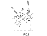
図5に示されるように、第2の傾斜角度βは、外表面30に対して接線方向でありかつ回転軸(X)に対して直角である直線(D2)とオリフィスの軸線(Y)との間に形成される配向角度であるように、各オリフィスについて規定される。
As shown in FIG. 5, the second inclination angle β is defined by a straight line (D2) that is tangential to the
オリフィス48の第1の角度αおよび/または第2の角度βが0°から90°までの範囲にある場合、オリフィス48は、2次空気システム12によって抽気される空気の量の損失に対して耐汚染性を改善する。逆に、オリフィス48の第1の角度αおよび/または第2の角度βが90°から180°までの範囲にある場合、オリフィス48は、汚染に対する頑健性を損なうことに対して2次空気システム12によって抽気される空気の量を増加させる。
If the first angle α and / or the second angle β of the
したがって、2次空気システム12を構成する各オリフィス48の第1の角度αおよび/または第2の角度βに作用することによって、抽気される酸化剤ガスの量と2次空気システム12の汚染に対する頑健性との間の妥協点を変更または調整することができる。さらに、前記2次空気システム12を構成する各オリフィス48の第1の角度αおよび/または第2の角度βに作用することによって、圧縮機の所与の回転速度について抽気される酸化剤ガスの量を調整することができる。
Accordingly, by acting on the first angle α and / or the second angle β of each
その結果として、各オリフィス48を通して流れる空気の流量は、第1の傾斜角度αを第1の所定値に設定することによって、および/または第2の傾斜角度βを第2の所定値に設定することによって予め定められ得る。したがって、圧縮機の所与の回転速度について、第1の角度αの値および/または第2の角度βの値は、オリフィス48を通して流れる空気の流量を所定値に調整できるようにするパラメータであることが理解され得る。
As a result, the flow rate of air flowing through each
もちろん、オリフィス48の上で記述した実施形態は、限定的な性質のものではない。たとえば、ハブ28の他にロータ18の部分にオリフィスを作ることができる。また、軸方向の位置決め、および/または方位位置、および/または半径方向位置、および/または第1の角度α、および/または第2の角度βを変更しているオリフィス48を提供することもできる。
Of course, the embodiment described above
Claims (8)
Applications Claiming Priority (3)
| Application Number | Priority Date | Filing Date | Title |
|---|---|---|---|
| FR0952227A FR2944060B1 (en) | 2009-04-06 | 2009-04-06 | SECONDARY AIR SYSTEM FOR CENTRIFUGAL OR MIXED COMPRESSOR |
| FR0952227 | 2009-04-06 | ||
| PCT/FR2010/050605 WO2010116071A1 (en) | 2009-04-06 | 2010-03-31 | Air bleed having an inertial filter in the tandem rotor of a compressor |
Publications (3)
| Publication Number | Publication Date |
|---|---|
| JP2012522938A JP2012522938A (en) | 2012-09-27 |
| JP2012522938A5 JP2012522938A5 (en) | 2013-05-02 |
| JP5497150B2 true JP5497150B2 (en) | 2014-05-21 |
Family
ID=40810171
Family Applications (1)
| Application Number | Title | Priority Date | Filing Date |
|---|---|---|---|
| JP2012504049A Expired - Fee Related JP5497150B2 (en) | 2009-04-06 | 2010-03-31 | Extraction with internal filter in the tandem rotor of the compressor |
Country Status (11)
| Country | Link |
|---|---|
| US (1) | US9611862B2 (en) |
| EP (1) | EP2417359B1 (en) |
| JP (1) | JP5497150B2 (en) |
| KR (1) | KR101647534B1 (en) |
| CN (1) | CN102388224B (en) |
| CA (1) | CA2758078C (en) |
| ES (1) | ES2559932T3 (en) |
| FR (1) | FR2944060B1 (en) |
| PL (1) | PL2417359T3 (en) |
| RU (1) | RU2519009C2 (en) |
| WO (1) | WO2010116071A1 (en) |
Families Citing this family (20)
| Publication number | Priority date | Publication date | Assignee | Title |
|---|---|---|---|---|
| US8935926B2 (en) * | 2010-10-28 | 2015-01-20 | United Technologies Corporation | Centrifugal compressor with bleed flow splitter for a gas turbine engine |
| US8920128B2 (en) * | 2011-10-19 | 2014-12-30 | Honeywell International Inc. | Gas turbine engine cooling systems having hub-bleed impellers and methods for the production thereof |
| US20130320148A1 (en) * | 2012-06-05 | 2013-12-05 | Honeywell International Inc. | Impeller, centrifugal pump including the same, and aircraft fuel system including the centrifugal pump |
| US9512721B2 (en) * | 2012-07-20 | 2016-12-06 | Pratt & Whitney Canada Corp. | Compound cycle engine |
| US20140186170A1 (en) * | 2012-12-27 | 2014-07-03 | Ronald E. Graf | Centrifugal Expanders And Compressors Each Using Rotors In Both Flow Going From Periphery To Center And Flow Going From Center To Periphery Their Use In Engines Both External Heat And Internal Combustion. Means to convert radial inward flow to radial outward flow with less eddy currents |
| DE102015214864A1 (en) | 2015-08-04 | 2017-02-09 | Bosch Mahle Turbo Systems Gmbh & Co. Kg | Compressor wheel with wavy wheel back |
| CN105952537A (en) * | 2016-04-22 | 2016-09-21 | 山东元动力科技有限公司 | Micro turbojet engine |
| CN105952538A (en) * | 2016-04-22 | 2016-09-21 | 山东元动力科技有限公司 | Micro turbojet engine |
| CN105952539A (en) * | 2016-04-22 | 2016-09-21 | 山东元动力科技有限公司 | Micro turbojet engine |
| US10683809B2 (en) * | 2016-05-10 | 2020-06-16 | General Electric Company | Impeller-mounted vortex spoiler |
| FR3065030B1 (en) * | 2017-04-05 | 2021-01-22 | Safran Helicopter Engines | INTERNAL COMBUSTION ENGINE |
| CN109209980B (en) * | 2017-06-30 | 2020-06-05 | 中国航发商用航空发动机有限责任公司 | Guide plate for axial flow compressor |
| CN108194419B (en) * | 2018-01-11 | 2019-10-11 | 南京航空航天大学 | The small aperture of centrifugal compressor circumferential direction large-spacing, which is blown, takes out joint pulse excitation casing |
| US11421708B2 (en) | 2018-03-16 | 2022-08-23 | Carrier Corporation | Refrigeration system mixed-flow compressor |
| CN110094361A (en) * | 2019-04-02 | 2019-08-06 | 中国北方发动机研究所(天津) | A kind of dynamoelectric compressor impeller |
| CN114651131A (en) * | 2019-11-13 | 2022-06-21 | 丹佛斯公司 | Active unloading device for mixed flow compressor |
| JP2022056948A (en) * | 2020-09-30 | 2022-04-11 | 株式会社豊田自動織機 | Centrifugal compressor |
| CN113107867B (en) * | 2021-05-11 | 2022-05-03 | 北京航空航天大学 | Centrifugal compressor water spray structure with circumferential arrangement |
| US11761632B2 (en) | 2021-08-05 | 2023-09-19 | General Electric Company | Combustor swirler with vanes incorporating open area |
| CN113969899A (en) * | 2021-09-03 | 2022-01-25 | 北京动力机械研究所 | Shafting structure for centrifugal turbine low-temperature helium compressor |
Family Cites Families (55)
| Publication number | Priority date | Publication date | Assignee | Title |
|---|---|---|---|---|
| US1488582A (en) * | 1922-01-13 | 1924-04-01 | Westinghouse Electric & Mfg Co | Elastic-fluid turbine |
| US2283176A (en) * | 1937-11-29 | 1942-05-19 | Turbo Engineering Corp | Elastic fluid mechanism |
| US2620123A (en) * | 1946-05-31 | 1952-12-02 | Continental Aviat & Engineerin | Cooling system for combustion gas turbines |
| US2709893A (en) * | 1949-08-06 | 1955-06-07 | Laval Steam Turbine Co | Gas turbine power plant with heat exchanger and cooling means |
| US2797858A (en) * | 1954-03-22 | 1957-07-02 | Garrett Corp | Radial compressors or turbines |
| US3493169A (en) * | 1968-06-03 | 1970-02-03 | United Aircraft Corp | Bleed for compressor |
| US3582232A (en) * | 1969-06-02 | 1971-06-01 | United Aircraft Canada | Radial turbine rotor |
| US3927952A (en) * | 1972-11-20 | 1975-12-23 | Garrett Corp | Cooled turbine components and method of making the same |
| FR2230229A5 (en) * | 1973-05-16 | 1974-12-13 | Onera (Off Nat Aerospatiale) | |
| US3937013A (en) * | 1974-06-27 | 1976-02-10 | General Motors Corporation | By-pass jet engine with centrifugal flow compressor |
| DE2457231C2 (en) * | 1974-12-04 | 1976-11-25 | Motoren Turbinen Union | IMPELLER FOR A FAST RUNNING TURBO MACHINE |
| US3958905A (en) * | 1975-01-27 | 1976-05-25 | Deere & Company | Centrifugal compressor with indexed inducer section and pads for damping vibrations therein |
| DE2828124C2 (en) * | 1978-06-27 | 1981-11-19 | M.A.N. Maschinenfabrik Augsburg-Nürnberg AG, 4200 Oberhausen | Procedure to prevent pumping of turbo compressors |
| US4221540A (en) * | 1978-09-28 | 1980-09-09 | Savonuzzi Giovanni F | Bladed rotor for a centripetal turbine |
| US4428715A (en) * | 1979-07-02 | 1984-01-31 | Caterpillar Tractor Co. | Multi-stage centrifugal compressor |
| US4335997A (en) * | 1980-01-16 | 1982-06-22 | General Motors Corporation | Stress resistant hybrid radial turbine wheel |
| FR2491549B1 (en) | 1980-10-08 | 1985-07-05 | Snecma | DEVICE FOR COOLING A GAS TURBINE, BY TAKING AIR FROM THE COMPRESSOR |
| US4416581A (en) * | 1982-02-16 | 1983-11-22 | Elliott Turbomachinery Co., Inc. | Method and apparatus for cooling an expander |
| US4653976A (en) * | 1982-09-30 | 1987-03-31 | General Electric Company | Method of compressing a fluid flow in a multi stage centrifugal impeller |
| US4502837A (en) * | 1982-09-30 | 1985-03-05 | General Electric Company | Multi stage centrifugal impeller |
| US4587700A (en) * | 1984-06-08 | 1986-05-13 | The Garrett Corporation | Method for manufacturing a dual alloy cooled turbine wheel |
| US4664598A (en) * | 1984-10-05 | 1987-05-12 | Reliance Electric Company | Unitized quick-assembly fan |
| CN86102105A (en) * | 1986-03-26 | 1987-10-14 | 鲁道夫·德雷斯马 | Compressor |
| US4759688A (en) * | 1986-12-16 | 1988-07-26 | Allied-Signal Inc. | Cooling flow side entry for cooled turbine blading |
| US4800717A (en) | 1986-12-22 | 1989-01-31 | Sundstrand Corporation | Turbine rotor cooling |
| US5105616A (en) * | 1989-12-07 | 1992-04-21 | Sundstrand Corporation | Gas turbine with split flow radial compressor |
| US5832715A (en) * | 1990-02-28 | 1998-11-10 | Dev; Sudarshan Paul | Small gas turbine engine having enhanced fuel economy |
| JPH03260336A (en) * | 1990-03-12 | 1991-11-20 | Mitsubishi Heavy Ind Ltd | Bleed device of centrifugal compressor |
| DE4029331C1 (en) * | 1990-09-15 | 1992-01-30 | Mtu Muenchen Gmbh | |
| US5215439A (en) * | 1991-01-15 | 1993-06-01 | Northern Research & Engineering Corp. | Arbitrary hub for centrifugal impellers |
| RU2093711C1 (en) * | 1991-06-14 | 1997-10-20 | Акционерное общество "Омское машиностроительное конструкторское бюро" | Gas-turbine engine antisurge device |
| JPH0586901A (en) * | 1991-09-20 | 1993-04-06 | Hitachi Ltd | Gas turbine |
| US6004095A (en) * | 1996-06-10 | 1999-12-21 | Massachusetts Institute Of Technology | Reduction of turbomachinery noise |
| TW336270B (en) * | 1997-01-17 | 1998-07-11 | Sanyo Electric Ltd | Compressor and air conditioner |
| JP3518447B2 (en) * | 1999-11-05 | 2004-04-12 | 株式会社日立製作所 | Gas turbine, gas turbine device, and refrigerant recovery method for gas turbine rotor blade |
| US6276896B1 (en) * | 2000-07-25 | 2001-08-21 | Joseph C. Burge | Apparatus and method for cooling Axi-Centrifugal impeller |
| US6589013B2 (en) * | 2001-02-23 | 2003-07-08 | Macro-Micro Devices, Inc. | Fluid flow controller |
| US6578351B1 (en) * | 2001-08-29 | 2003-06-17 | Pratt & Whitney Canada Corp. | APU core compressor providing cooler air supply |
| US6935840B2 (en) * | 2002-07-15 | 2005-08-30 | Pratt & Whitney Canada Corp. | Low cycle fatigue life (LCF) impeller design concept |
| US7370787B2 (en) * | 2003-12-15 | 2008-05-13 | Pratt & Whitney Canada Corp. | Compressor rotor and method for making |
| US7273352B2 (en) * | 2004-01-09 | 2007-09-25 | United Technologies Corporation | Inlet partial blades for structural integrity and performance |
| JP4675638B2 (en) * | 2005-02-08 | 2011-04-27 | 本田技研工業株式会社 | Secondary air supply device for gas turbine engine |
| US7156612B2 (en) * | 2005-04-05 | 2007-01-02 | Pratt & Whitney Canada Corp. | Spigot arrangement for a split impeller |
| US7559745B2 (en) * | 2006-03-21 | 2009-07-14 | United Technologies Corporation | Tip clearance centrifugal compressor impeller |
| US8075247B2 (en) * | 2007-12-21 | 2011-12-13 | Pratt & Whitney Canada Corp. | Centrifugal impeller with internal heating |
| US20090297344A1 (en) * | 2008-05-30 | 2009-12-03 | Controlled Power Technologies Limited | Rotors and manufacturing methods for rotors |
| FR2937385B1 (en) * | 2008-10-17 | 2010-12-10 | Turbomeca | DIFFUSER WITH AUBES A ORIFICES |
| US8231341B2 (en) * | 2009-03-16 | 2012-07-31 | Pratt & Whitney Canada Corp. | Hybrid compressor |
| IT1394295B1 (en) * | 2009-05-08 | 2012-06-06 | Nuovo Pignone Spa | CENTRIFUGAL IMPELLER OF THE CLOSED TYPE FOR TURBOMACCHINE, COMPONENT FOR SUCH A IMPELLER, TURBOMACCHINA PROVIDED WITH THAT IMPELLER AND METHOD OF REALIZING SUCH A IMPELLER |
| US20110167792A1 (en) * | 2009-09-25 | 2011-07-14 | James Edward Johnson | Adaptive engine |
| US8920128B2 (en) * | 2011-10-19 | 2014-12-30 | Honeywell International Inc. | Gas turbine engine cooling systems having hub-bleed impellers and methods for the production thereof |
| JP5490338B2 (en) * | 2012-03-22 | 2014-05-14 | パナソニック株式会社 | Centrifugal compressor |
| US9897107B2 (en) * | 2013-02-22 | 2018-02-20 | Mitsubishi Heavy Industries, Ltd. | Compressor wheel and unbalance detection device for compressor assembly |
| GB201308381D0 (en) * | 2013-05-09 | 2013-06-19 | Imp Innovations Ltd | A modified inlet duct |
| FR3007086B1 (en) * | 2013-06-18 | 2015-07-03 | Cryostar Sas | CENTRIFUGAL WHEEL |
-
2009
- 2009-04-06 FR FR0952227A patent/FR2944060B1/en active Active
-
2010
- 2010-03-31 EP EP10717695.0A patent/EP2417359B1/en active Active
- 2010-03-31 PL PL10717695T patent/PL2417359T3/en unknown
- 2010-03-31 US US13/263,187 patent/US9611862B2/en active Active
- 2010-03-31 CN CN201080016185.5A patent/CN102388224B/en active Active
- 2010-03-31 ES ES10717695.0T patent/ES2559932T3/en active Active
- 2010-03-31 WO PCT/FR2010/050605 patent/WO2010116071A1/en active Application Filing
- 2010-03-31 RU RU2011144876/06A patent/RU2519009C2/en not_active IP Right Cessation
- 2010-03-31 JP JP2012504049A patent/JP5497150B2/en not_active Expired - Fee Related
- 2010-03-31 CA CA2758078A patent/CA2758078C/en active Active
- 2010-03-31 KR KR1020117025530A patent/KR101647534B1/en active IP Right Grant
Also Published As
| Publication number | Publication date |
|---|---|
| FR2944060A1 (en) | 2010-10-08 |
| ES2559932T3 (en) | 2016-02-16 |
| US9611862B2 (en) | 2017-04-04 |
| WO2010116071A1 (en) | 2010-10-14 |
| PL2417359T3 (en) | 2016-04-29 |
| CN102388224A (en) | 2012-03-21 |
| EP2417359B1 (en) | 2015-12-16 |
| KR20120013959A (en) | 2012-02-15 |
| KR101647534B1 (en) | 2016-08-10 |
| EP2417359A1 (en) | 2012-02-15 |
| CA2758078A1 (en) | 2010-10-14 |
| CN102388224B (en) | 2014-09-17 |
| US20120036865A1 (en) | 2012-02-16 |
| FR2944060B1 (en) | 2013-07-19 |
| JP2012522938A (en) | 2012-09-27 |
| CA2758078C (en) | 2017-04-18 |
| RU2519009C2 (en) | 2014-06-10 |
| RU2011144876A (en) | 2013-05-20 |
Similar Documents
| Publication | Publication Date | Title |
|---|---|---|
| JP5497150B2 (en) | Extraction with internal filter in the tandem rotor of the compressor | |
| EP1793086B1 (en) | Aerofoil for a gas turbine comprising a particle deflector | |
| EP1818512B1 (en) | Particle collector for gas turbine engine | |
| CA2844552C (en) | Compressor shroud reverse bleed holes | |
| EP3260687A1 (en) | Inlet particle separator system with pre-cleaner flow passage | |
| US7874794B2 (en) | Blade row for a rotary machine and method of fabricating same | |
| EP2778427A2 (en) | Compressor bleed self-recirculating system | |
| JP2012522938A5 (en) | ||
| CA2833986A1 (en) | Low hub-to-tip ratio fan for a turbofan gas turbine engine | |
| JP2001214891A (en) | Method and device for introducing air flow to compressor bore | |
| US8851833B2 (en) | Blades | |
| CA2920277C (en) | Blade or vane arrangement for a gas turbine engine | |
| US8241005B2 (en) | Gas turbine engine centrifugal impeller | |
| KR101891853B1 (en) | Centrifugal Compressor Impeller | |
| US10227930B2 (en) | Compressor bleed systems in turbomachines and methods of extracting compressor airflow | |
| EP2562370A2 (en) | Gas turbine engines with mid-impeller bleed cooling air | |
| CN107178425A (en) | Gas-turbine unit with exhaust passage | |
| US20170241432A1 (en) | Compressor rotor for supersonic flutter and/or resonant stress mitigation | |
| CA2930755C (en) | Compressor airfoil with compound leading edge profile | |
| US20170298819A1 (en) | Turbine impeller | |
| WO2014189702A1 (en) | A balanced mixed flow turbine wheel | |
| EP3875734A1 (en) | Exhaust diffuser strut for reducing flow separation | |
| CN113389599B (en) | Turbine engine with high acceleration and low blade turning airfoils | |
| CN105370324A (en) | Turbine nozzle with relief cut |
Legal Events
| Date | Code | Title | Description |
|---|---|---|---|
| A521 | Written amendment |
Free format text: JAPANESE INTERMEDIATE CODE: A523 Effective date: 20130311 |
|
| A621 | Written request for application examination |
Free format text: JAPANESE INTERMEDIATE CODE: A621 Effective date: 20130311 |
|
| A977 | Report on retrieval |
Free format text: JAPANESE INTERMEDIATE CODE: A971007 Effective date: 20140128 |
|
| TRDD | Decision of grant or rejection written | ||
| A01 | Written decision to grant a patent or to grant a registration (utility model) |
Free format text: JAPANESE INTERMEDIATE CODE: A01 Effective date: 20140204 |
|
| A61 | First payment of annual fees (during grant procedure) |
Free format text: JAPANESE INTERMEDIATE CODE: A61 Effective date: 20140305 |
|
| R150 | Certificate of patent or registration of utility model |
Ref document number: 5497150 Country of ref document: JP Free format text: JAPANESE INTERMEDIATE CODE: R150 |
|
| R250 | Receipt of annual fees |
Free format text: JAPANESE INTERMEDIATE CODE: R250 |
|
| R250 | Receipt of annual fees |
Free format text: JAPANESE INTERMEDIATE CODE: R250 |
|
| R250 | Receipt of annual fees |
Free format text: JAPANESE INTERMEDIATE CODE: R250 |
|
| LAPS | Cancellation because of no payment of annual fees |