JP5496203B2 - Method for changing transmit power pattern in a multi-cell environment - Google Patents
Method for changing transmit power pattern in a multi-cell environment Download PDFInfo
- Publication number
- JP5496203B2 JP5496203B2 JP2011523124A JP2011523124A JP5496203B2 JP 5496203 B2 JP5496203 B2 JP 5496203B2 JP 2011523124 A JP2011523124 A JP 2011523124A JP 2011523124 A JP2011523124 A JP 2011523124A JP 5496203 B2 JP5496203 B2 JP 5496203B2
- Authority
- JP
- Japan
- Prior art keywords
- cluster
- power
- base station
- transmission
- base stations
- Prior art date
- Legal status (The legal status is an assumption and is not a legal conclusion. Google has not performed a legal analysis and makes no representation as to the accuracy of the status listed.)
- Active
Links
- 238000000034 method Methods 0.000 title claims description 49
- 230000005540 biological transmission Effects 0.000 claims description 131
- 238000004891 communication Methods 0.000 claims description 18
- 230000008859 change Effects 0.000 claims description 13
- 238000013507 mapping Methods 0.000 claims description 9
- 230000007480 spreading Effects 0.000 claims description 3
- 238000003892 spreading Methods 0.000 claims description 3
- 238000004422 calculation algorithm Methods 0.000 description 36
- 210000004027 cell Anatomy 0.000 description 16
- 238000012545 processing Methods 0.000 description 12
- 230000008569 process Effects 0.000 description 8
- 238000005457 optimization Methods 0.000 description 7
- 230000008901 benefit Effects 0.000 description 5
- 238000010586 diagram Methods 0.000 description 5
- 238000009826 distribution Methods 0.000 description 4
- 230000003287 optical effect Effects 0.000 description 4
- 238000003860 storage Methods 0.000 description 4
- 239000013598 vector Substances 0.000 description 4
- 238000013461 design Methods 0.000 description 3
- 230000006870 function Effects 0.000 description 3
- 230000000670 limiting effect Effects 0.000 description 3
- 230000002829 reductive effect Effects 0.000 description 3
- 230000001413 cellular effect Effects 0.000 description 2
- 238000004590 computer program Methods 0.000 description 2
- 238000011161 development Methods 0.000 description 2
- 230000018109 developmental process Effects 0.000 description 2
- 230000009467 reduction Effects 0.000 description 2
- 238000013468 resource allocation Methods 0.000 description 2
- 230000003068 static effect Effects 0.000 description 2
- 210000003771 C cell Anatomy 0.000 description 1
- 241000257303 Hymenoptera Species 0.000 description 1
- 230000009471 action Effects 0.000 description 1
- 238000013459 approach Methods 0.000 description 1
- 238000004364 calculation method Methods 0.000 description 1
- 230000015556 catabolic process Effects 0.000 description 1
- 230000008878 coupling Effects 0.000 description 1
- 238000010168 coupling process Methods 0.000 description 1
- 238000005859 coupling reaction Methods 0.000 description 1
- 125000004122 cyclic group Chemical group 0.000 description 1
- 238000006731 degradation reaction Methods 0.000 description 1
- 230000001419 dependent effect Effects 0.000 description 1
- 230000001771 impaired effect Effects 0.000 description 1
- 230000006872 improvement Effects 0.000 description 1
- 230000002452 interceptive effect Effects 0.000 description 1
- 230000007774 longterm Effects 0.000 description 1
- 238000007726 management method Methods 0.000 description 1
- 238000005259 measurement Methods 0.000 description 1
- 230000007246 mechanism Effects 0.000 description 1
- 230000000116 mitigating effect Effects 0.000 description 1
- 238000012986 modification Methods 0.000 description 1
- 230000004048 modification Effects 0.000 description 1
- 230000036961 partial effect Effects 0.000 description 1
- 230000000737 periodic effect Effects 0.000 description 1
- 230000008054 signal transmission Effects 0.000 description 1
- URWAJWIAIPFPJE-YFMIWBNJSA-N sisomycin Chemical compound O1C[C@@](O)(C)[C@H](NC)[C@@H](O)[C@H]1O[C@@H]1[C@@H](O)[C@H](O[C@@H]2[C@@H](CC=C(CN)O2)N)[C@@H](N)C[C@H]1N URWAJWIAIPFPJE-YFMIWBNJSA-N 0.000 description 1
- 230000003595 spectral effect Effects 0.000 description 1
- 238000001228 spectrum Methods 0.000 description 1
- 239000000126 substance Substances 0.000 description 1
- 230000009897 systematic effect Effects 0.000 description 1
- 238000012549 training Methods 0.000 description 1
- 238000013519 translation Methods 0.000 description 1
Images


Classifications
-
- H—ELECTRICITY
- H04—ELECTRIC COMMUNICATION TECHNIQUE
- H04W—WIRELESS COMMUNICATION NETWORKS
- H04W52/00—Power management, e.g. TPC [Transmission Power Control], power saving or power classes
- H04W52/04—TPC
- H04W52/30—TPC using constraints in the total amount of available transmission power
- H04W52/34—TPC management, i.e. sharing limited amount of power among users or channels or data types, e.g. cell loading
-
- H—ELECTRICITY
- H04—ELECTRIC COMMUNICATION TECHNIQUE
- H04L—TRANSMISSION OF DIGITAL INFORMATION, e.g. TELEGRAPHIC COMMUNICATION
- H04L5/00—Arrangements affording multiple use of the transmission path
- H04L5/0001—Arrangements for dividing the transmission path
- H04L5/0003—Two-dimensional division
- H04L5/0005—Time-frequency
- H04L5/0007—Time-frequency the frequencies being orthogonal, e.g. OFDM(A), DMT
-
- H—ELECTRICITY
- H04—ELECTRIC COMMUNICATION TECHNIQUE
- H04L—TRANSMISSION OF DIGITAL INFORMATION, e.g. TELEGRAPHIC COMMUNICATION
- H04L5/00—Arrangements affording multiple use of the transmission path
- H04L5/003—Arrangements for allocating sub-channels of the transmission path
- H04L5/0032—Distributed allocation, i.e. involving a plurality of allocating devices, each making partial allocation
-
- H—ELECTRICITY
- H04—ELECTRIC COMMUNICATION TECHNIQUE
- H04W—WIRELESS COMMUNICATION NETWORKS
- H04W16/00—Network planning, e.g. coverage or traffic planning tools; Network deployment, e.g. resource partitioning or cells structures
- H04W16/24—Cell structures
- H04W16/30—Special cell shapes, e.g. doughnuts or ring cells
Description
[0003]本発明の実施形態は、ワイヤレス通信システムにおける協調送信の分野に関し、より詳細には、本発明の実施形態は、クラスタ内の異なる基地局が一緒に動作して、複数の周波数、帯域、及び/又はチャネル上において異なる電力レベルで送信するように、またすべてのクラスタにわたって送信電力の変更を合同で協調させるように、マルチ基地局環境全体において協調した方式でクラスタ内の基地局の送信電力を変更することに関する。 [0003] Embodiments of the present invention relate to the field of coordinated transmissions in wireless communication systems, and more particularly, embodiments of the present invention operate with multiple base stations in different clusters operating together in multiple frequencies, bands. And / or transmission of base stations in a cluster in a coordinated manner across the entire multi-base station environment to transmit at different power levels on the channel and to coordinate transmission power changes across all clusters jointly. It relates to changing power.
[優先権]
[0001]本特許出願は、2008年8月13日に出願された、「A Method for Joint User Scheduling and MIMO Transmission by Using Varying Transmit Power Patterns and Varying Antenna−User Coordination Patterns in a Multi−Cell Environment」と題する、対応する特許仮出願第61/089096号の優先権を主張し、同特許仮出願を参照により組み込む。
[priority]
[0001] This patent application was filed on August 13, 2008, “A Method for Joint User Scheduling and MIMO Transmission by Using TransCensing Power Patterns and Varying Ants. Claims the priority of the corresponding provisional patent application 61/089096, which is incorporated by reference.
[関連出願]
[0002]本出願は、本出願と同時に出願された以下の出願に、すなわち、2009年8月10日に出願された、「A Variable Coordination Pattern Approach for Improving Performance in Multi−Cell or Multi−Antenna Environments」と題する、米国特許出願第12/538729号、及び2009年8月10日に出願された、「A Method of Combined User and Coordination Pattern Scheduling Over Varying Antenna and Base Station Coordination Patterns in a Multi−Cell Environment」と題する、米国特許出願第12/538733号に関連する。
[Related applications]
[0002] This application is filed in the following application filed concurrently with the present application, namely, “A Variable Coordination Pattern Appropriation for Multi-Cell or Multi-Ancient Enantien Entrant, filed on August 10, 2009. U.S. patent application Ser. When To related to U.S. Patent Application No. 12/538733.
[0004]新興及び将来のワイヤレスシステムは、与えられた送信帯域幅内で達成可能なデータレートを高めるために、無線周波数スペクトルの利用においてますます高い効率を必要とする。単位帯域幅当たり達成可能なスループットの増加は、信号処理を用いて組み合わされる複数の送受信アンテナを利用することによって達成することができる。実際に、多くの最近開発された技法及び新興の規格は、基地局において複数のアンテナを利用することに基づいて、ワイヤレスシステムの有効データレートを損なうことなく、ワイヤレス媒体上でのデータ通信の信頼性を改善する。代替として、複数のアンテナは、単位帯域幅当たり達成可能なデータレートを高めるために使用することができる。 [0004] Emerging and future wireless systems require increasingly high efficiency in utilizing the radio frequency spectrum in order to increase the data rates achievable within a given transmission bandwidth. The increase in throughput achievable per unit bandwidth can be achieved by utilizing multiple transmit and receive antennas that are combined using signal processing. In fact, many recently developed techniques and emerging standards are based on the use of multiple antennas at the base station, and the reliability of data communication over the wireless medium without compromising the effective data rate of the wireless system. Improve sex. Alternatively, multiple antennas can be used to increase the achievable data rate per unit bandwidth.
[0005]具体的には、ワイヤレス通信における最近の進展は、(例えば、基地局で複数の送信アンテナを使用して)時間及び空間にわたって合同でシンボルを符号化することによって、信頼性(ダイバーシチ)利益に加えて、基地局から各セルラユーザへの有効データレートの増加も獲得できることを示している。これらの多重化(スループット)利得及びダイバーシチ利益は、システムにおける送受信アンテナの数によって決定付けられる多重化−ダイバーシチトレードオフ曲線(multiplexing−diversity trade−offs curve)によって基本的に制約されるという意味で、配備されるシステムにおける送受信アンテナの数に本質的に依存する。多くの送受信アンテナを利用することによって、非常に高いスペクトル効率を達成する、非常に高いレートの設計が示された。そのようなMIMO方式は、シングルユーザMIMOシステムと呼ばれるものの基礎を形成する。これらの方式によれば、割り当てられたチャネル上で複数のアンテナを介して送信される信号に情報搬送ストリームを符号化することによって、複数のストリームを単一のユーザに送信するために、時間−周波数スロットの異なる組に対応するチャネルが使用される。その場合、スケジューラを使用して、SISO送信で行われるのと同様の方法で、異なるユーザのための送信を異なるチャネル上にスケジュールする。 [0005] Specifically, recent developments in wireless communications have led to reliability (diversity) by encoding symbols jointly over time and space (eg, using multiple transmit antennas at a base station). In addition to profit, it also shows that an increase in effective data rate from the base station to each cellular user can be obtained. These multiplexing (throughput) gains and diversity benefits are essentially constrained by a multiplexing-diversity trade-offs curve determined by the number of transmit and receive antennas in the system, Depends essentially on the number of transmit and receive antennas in the deployed system. By utilizing many transmit and receive antennas, very high rate designs have been shown that achieve very high spectral efficiency. Such a MIMO scheme forms the basis of what is referred to as a single user MIMO system. According to these schemes, the time--in order to transmit multiple streams to a single user by encoding the information carrying stream into a signal transmitted via multiple antennas on the assigned channel. Channels corresponding to different sets of frequency slots are used. In that case, a scheduler is used to schedule transmissions for different users on different channels in a manner similar to that performed for SISO transmissions.
[0006]最近、基地局でいくつかの送信アンテナが利用可能であり、すべての送信−受信チャネルが送信基地局に知られているならば、1つ又は2つのアンテナを利用する単純な移動体を用いて、非常に高い合計レート(すなわち、送信先であるユーザのレートの合計)が獲得できることが示された。これらの技法は、マルチユーザMIMO(MU−MIMO)方式と呼ばれる。一般に、これらの方式によって達成可能なレートは、基地局で利用可能なチャネル推定の品質に強く依存する。ゼロ強制(又はブロックゼロ強制)MU−MIMOプリコーダとして知られる、マルチユーザMIMOプリコーダの最も簡単なクラスの1つは、各ユーザの受信機が雑音内に自身の信号を「見出す」ように、送信されるユーザの信号を線形プリコードするために、送信/受信アンテナペアの間のすべてのチャネルについての知識を使用する。 [0006] Recently, if several transmit antennas are available at the base station and all transmit-receive channels are known to the transmit base station, a simple mobile that utilizes one or two antennas. It was shown that a very high total rate (i.e., the sum of the rates of the destination users) can be obtained using. These techniques are called multi-user MIMO (MU-MIMO) schemes. In general, the rate achievable by these schemes is strongly dependent on the quality of channel estimation available at the base station. One of the simplest classes of multi-user MIMO precoders, known as zero-forced (or block zero-forced) MU-MIMO precoders, transmits so that each user's receiver “finds” its signal in noise. Knowledge of all channels between transmit / receive antenna pairs is used to linearly pre-code the transmitted user's signal.
[0007]既存のマルチセル配備は、異なるユーザに不均衡なスループットを提供することが知られており、各セルのエッジにいるユーザは、そのセルの中央にいるユーザと比べて、スループットが劣る。MIMO送信を使用するマルチセル配備のために、多くの方式が提案されている。いくつかのマルチセル配備は、セル間での協調を行わない孤立セル合同スケジューリング/MIMOプリコーディングアルゴリズムを利用する。協調は、各セル内のアンテナに制限される。また、これらの方式は、容易に拡張可能であるが、(セルの外部に配置されたアンテナから来る)干渉によって制限され、エッジスループットが大きく損なわれる。いくつかの完全に協調するマルチセル配備は、干渉によって制限されず、(増加した電力を用いた)任意に高い合計スループットと、任意に高いエッジスループットを提供することができる。しかし、それらは、すべてのセルにわたってすべての送信アンテナを協調させる必要があるので、拡張可能ではない。また、ネットワーク全体におけるアンテナの数、及びスケジュールする必要があるユーザの数とともに、複雑さが非常に速やかに増加し、すぐに非実用的になる。したがって、この方式は、実用的ないずれの方式の性能にも上限を課す。 [0007] Existing multi-cell deployments are known to provide unbalanced throughput for different users, with users at the edge of each cell having poor throughput compared to users at the center of the cell. Many schemes have been proposed for multi-cell deployment using MIMO transmission. Some multi-cell deployments utilize isolated cell joint scheduling / MIMO precoding algorithms that do not coordinate between cells. Coordination is limited to antennas in each cell. Also, these schemes can be easily expanded, but are limited by interference (coming from antennas located outside the cell), and edge throughput is greatly impaired. Some fully coordinated multi-cell deployments are not limited by interference and can provide arbitrarily high total throughput (with increased power) and arbitrarily high edge throughput. However, they are not scalable as all transmit antennas need to be coordinated across all cells. Also, along with the number of antennas in the entire network and the number of users that need to be scheduled, the complexity increases very quickly and quickly becomes impractical. Therefore, this scheme places an upper limit on the performance of any practical scheme.
[0008]ロングタームエボリューション(LTE:Long−Term Evolution)と呼ばれる3G規格の現在の発展は、異なるチャネルの電力レベルが隣接セルにおいて異なるように調整される、セル間干渉(inter−cell interference)協調技法を提案する。結果として、エッジユーザによって経験される干渉は低減され、より高いデータレートを達成することができる。LTEは、各セル内のダウンリンクにおいて、シングルユーザMIMO(SU−MIMO)送信を仮定する。加えて、基地局(又はコントローラ)は、常にアンテナの同じ組を制御し、チャネルにわたる電力レベルは、時間とともに、また同じ1組のスケジューリング対象のユーザに対して変化しない。 [0008] The current development of the 3G standard, called Long-Term Evolution (LTE), is inter-cell interference coordination where the power levels of different channels are adjusted differently in neighboring cells. Suggest a technique. As a result, the interference experienced by edge users is reduced and higher data rates can be achieved. LTE assumes single user MIMO (SU-MIMO) transmission on the downlink in each cell. In addition, the base station (or controller) always controls the same set of antennas, and the power level across the channel does not change over time and for the same set of scheduled users.
[0009]本明細書では、マルチセルワイヤレス送信環境において送信電力パターンを変更するための方法及び装置が開示される。一実施形態では、方法は、ワイヤレス通信システム内の基地局のための送信電力協調パターンを変更して、基地局からなる1つのクラスタ内の及びクラスタにわたる基地局にわたって1組の仮想チャネル上の基地局電力を合同で変更するステップと、送信電力協調パターンに基づいて、基地局のグループがそれぞれのクラスタ内で1つ又は複数のユーザ端末に合同で送信するステップとを含む。 [0009] Disclosed herein are methods and apparatus for changing a transmit power pattern in a multi-cell wireless transmission environment. In one embodiment, the method modifies the transmit power coordination pattern for base stations in a wireless communication system so that bases on a set of virtual channels within a cluster of base stations and across base stations across clusters. Changing the station power jointly and transmitting the group of base stations jointly to one or more user terminals in each cluster based on the transmission power coordination pattern.
[0010]本発明は、以下で与えられる詳細な説明から、また本発明の様々な実施形態についての添付の図面からより十分に理解されるが、それらは、本発明を特定の実施形態に限定するものと解釈されるべきではなく、もっぱら説明及び理解のためのものと解釈されるべきである。 [0010] The invention will be more fully understood from the detailed description given below and from the accompanying drawings of various embodiments of the invention, which limit the invention to the specific embodiments. It should not be construed to be, but merely for explanation and understanding.
[0011]本発明の実施形態は、1組のコントローラ間でリソース及びユーザをシステマティックに協調させるマルチセル配備を含む。一実施形態では、各コントローラは、クラスタ又は基地局の一部である。一実施形態では、リソースの協調は、時間とともに変化する方法(例えば、時間とともに周期的に変化する方法)で起こる。特に、これらの方式は、以下のものの使用を、すなわち、(i)各コントローラによって制御される1組の送信アンテナ、(ii)各コントローラによって制御されるアンテナに課される送信電力限界、(iii)コントローラ別のスケジューリングについて検討される1組のユーザの使用を協調させる。本発明の実施形態は、時間/周波数スロット上でコントローラ毎に各チャネルに適用される電力レベルパターンを合同で変更する。より具体的には、基地局からなる1つのクラスタ内の及び他のクラスタにわたる基地局にわたって、基地局送信電力レベルがチャネル上に割り当てられる。すなわち、1つのクラスタ内の基地局の電力は、事前に、他のクラスタ内の基地局の関連する電力と合同で選択され、送信電力レベル割り当てが、(近隣クラスタを含む)他のクラスタにおける関連する割り当てと独立することなく、1組のチャネル1、2、...、Fにわたって、すべてが合同で変更される。これは、協調しないシステムと比較して、複雑さをあまり増大させることなく、すべてのユーザについて向上したスループットと、センタユーザとエッジユーザの間のより公平な性能をもたらす。
[0011] Embodiments of the present invention include a multi-cell deployment that systematically coordinates resources and users between a set of controllers. In one embodiment, each controller is part of a cluster or base station. In one embodiment, resource coordination occurs in a manner that changes over time (eg, a method that changes periodically over time). In particular, these schemes make use of the following: (i) a set of transmit antennas controlled by each controller; (ii) transmit power limits imposed on the antennas controlled by each controller; ) Coordinate the use of a set of users to be considered for controller-specific scheduling. Embodiments of the present invention jointly change the power level pattern applied to each channel for each controller on a time / frequency slot. More specifically, base station transmit power levels are assigned on a channel within a cluster of base stations and across base stations across other clusters. That is, the power of base stations in one cluster is pre-selected jointly with the associated power of base stations in other clusters, and the transmit power level assignment is related to other clusters (including neighboring clusters). A set of
[0012]以下の説明では、本発明のより完全な説明を提供するために、多くの詳細が説明される。しかし、本発明がこれらの特定の詳細なしでも実施できることは、当業者には明らかであろう。他の例では、よく知られた構造及びデバイスは、本発明を曖昧にしないために、詳細にではなく、ブロック図形式で示される。 [0012] In the following description, numerous details are set forth to provide a more thorough explanation of the present invention. However, it will be apparent to those skilled in the art that the present invention may be practiced without these specific details. In other instances, well-known structures and devices are shown in block diagram form, rather than in detail, in order not to obscure the present invention.
[0013]以下の詳細な説明のいくつかの部分は、コンピュータメモリ内のデータビットに対する操作のアルゴリズム及びシンボル表現によって提示される。これらのアルゴリズムによる説明及び表現は、自分の仕事の内容を他の当業者に最も効果的に伝えるために、データ処理分野の当業者によって使用される手段である。アルゴリズムは、ここでは、また一般に、所望の結果に到達する自己矛盾のないステップの系列であると考えられる。ステップは、物理的量の物理的操作を必要とするステップである。必ずしも必要ではないが、通常は、これらの量は、保存し、転送し、組み合わせ、比較し、及び他の方法で操作することが可能な、電気的又は磁気的な信号の形態をとる。主として一般的な慣習上の理由で、これらの信号をビット、値、要素、シンボル、文字、項、又は数などと呼ぶことが便利であると分かることがある。 [0013] Some portions of the detailed descriptions that follow are presented in terms of algorithms and symbolic representations of operations on data bits within a computer memory. These algorithmic descriptions and representations are the means used by those skilled in the data processing arts to most effectively convey the substance of their work to others skilled in the art. The algorithm is here and generally considered to be a self-consistent sequence of steps to reach the desired result. A step is a step that requires physical manipulation of physical quantities. Usually, though not necessarily, these quantities take the form of electrical or magnetic signals capable of being stored, transferred, combined, compared, and otherwise manipulated. It may prove convenient at times, principally for reasons of common usage, to refer to these signals as bits, values, elements, symbols, characters, terms, numbers, or the like.
[0014]しかし、これらの用語及び類似の用語のすべては、適切な物理的量に関連付けられ、これらの量に付された単に便利なラベルであるにすぎないことに留意されたい。別途具体的に述べられない限り、以下の説明から明らかなように、説明の全体において、「処理する」、又は「計算する」、又は「算定する」、又は「決定する」、又は「表示する」などの用語を利用した説明は、コンピュータシステムのレジスタ及びメモリ内の物理的(電子的)量として表現されるデータを操作及び変形して、コンピュータシステムのメモリ若しくはレジスタ内の、又は他のそのような情報記憶デバイス、伝送デバイス、若しくは表示デバイス内の物理的量として同様に表現される他のデータにする、コンピュータシステム又は同様の電子的なコンピューティングデバイスのアクション及びプロセスを指すことが理解される。 [0014] However, it is noted that all of these terms and similar terms are associated with the appropriate physical quantities and are merely convenient labels attached to these quantities. Unless specifically stated otherwise, as will be clear from the following description, in the entire description, “process”, “calculate”, “calculate”, “determine”, or “display” Is used to manipulate and transform data expressed as physical (electronic) quantities in a computer system's registers and memory, and in a computer system's memory or registers, or other It is understood to refer to actions and processes of a computer system or similar electronic computing device that result in other data that is also expressed as a physical quantity in an information storage device, transmission device, or display device. The
[0015]本発明は、本明細書の動作を実行するための装置にも関する。この装置は、必要とされる目的のために特別に構成することができ、又はコンピュータに保存されたコンピュータプログラムによって選択的に活動化又は再構成される汎用コンピュータを含むことができる。そのようなコンピュータプログラムは、フロッピディスク、光ディスク、CD−ROM、磁気光ディスクを含む任意のタイプのディスク、リードオンリメモリ(ROM)、ランダムアクセスメモリ(RAM)、EPROM、EEPROM、磁気若しくは光カード、又は電子的命令を保存するのに適した任意のタイプの媒体などの、しかしそれらに限定されない、コンピュータ可読記憶媒体に保存することができ、各々は、コンピュータシステムバスに結合される。 [0015] The present invention also relates to an apparatus for performing the operations herein. The apparatus can be specially configured for the required purposes, or can include a general purpose computer selectively activated or reconfigured by a computer program stored on the computer. Such a computer program can be any type of disk, including floppy disk, optical disk, CD-ROM, magnetic optical disk, read only memory (ROM), random access memory (RAM), EPROM, EEPROM, magnetic or optical card, or It can be stored on a computer readable storage medium, such as, but not limited to, any type of medium suitable for storing electronic instructions, each coupled to a computer system bus.
[0016]本明細書で提示されるアルゴリズム及び表示は、特定のコンピュータ又は他の装置のいずれにも、本質的に関係しない。本明細書の教示に従ったプログラムとともに、様々な汎用システムを使用することができ、又は必要とされる方法ステップを実行するために、より専門的な装置を構成することが便利であると分かることもある。様々なこれらのシステムに必要とされる構造は、以下の説明から明らかとなる。加えて、本発明は、特定のプログラミング言語のいずれかに関連して説明されない。本明細書で説明される本発明の教示を実施するために、様々なプログラミング言語が使用できることが理解されよう。 [0016] The algorithms and displays presented herein are not inherently related to any particular computer or other apparatus. Various general purpose systems can be used with programs in accordance with the teachings herein, or it will prove convenient to configure a more specialized apparatus to perform the required method steps. Sometimes. The required structure for a variety of these systems will appear from the description below. In addition, the present invention is not described with reference to any particular programming language. It will be appreciated that a variety of programming languages can be used to implement the teachings of the invention as described herein.
[0017]機械可読媒体は、機械(例えばコンピュータ)によって可読な形式で、情報を保存又は伝送するための任意の機構を含む。例えば、機械可読媒体は、リードオンリメモリ(「ROM」)、ランダムアクセスメモリ(「RAM」)、磁気ディスク記憶媒体、光記憶媒体、フラッシュメモリデバイスなどを含む。 [0017] A machine-readable medium includes any mechanism for storing or transmitting information in a form readable by a machine (eg, a computer). For example, machine-readable media include read only memory (“ROM”), random access memory (“RAM”), magnetic disk storage media, optical storage media, flash memory devices, and the like.
概要
[0018]ワイヤレス通信システムにおいて送信電力パターンを変更するための技法が説明される。一実施形態では、方法は、ワイヤレス通信システム内の基地局のための送信電力協調パターンを変更して、基地局からなる1つのクラスタ内の及びクラスタにわたる基地局にわたって1組の仮想チャネル上の基地局送信電力を合同で変更するステップと、合同で変更された送信電力協調パターンに基づいて、基地局のグループがそれぞれのクラスタ内で1つ又は複数のユーザ端末に合同で送信するステップとを含む。このようにして、1つのクラスタ内の基地局の送信電力は、他のクラスタの基地局の関連する送信電力とともに合同で選択され、1組の仮想チャネルにわたって、すべてが合同で変更される。仮想チャネルは、周波数サブバンド、時間−周波数スロット、又は例えば拡散符号などの他の送信リソースとすることができる。
Overview
[0018] Techniques for changing a transmit power pattern in a wireless communication system are described. In one embodiment, the method modifies the transmit power coordination pattern for base stations in a wireless communication system so that bases on a set of virtual channels within a cluster of base stations and across base stations across clusters. A step of jointly changing station transmission power and a step of jointly transmitting a group of base stations to one or more user terminals in each cluster based on the jointly changed transmission power coordination pattern. . In this way, the transmission power of base stations in one cluster is selected jointly with the associated transmission power of base stations in other clusters, and all are changed jointly across a set of virtual channels. The virtual channel may be a frequency subband, a time-frequency slot, or other transmission resource such as a spreading code.
[0019]一実施形態では、第1の複数のクラスタ間で送信電力協調パターンを変更するステップは、1つのクラスタ内の少なくとも2つの基地局の送信電力が仮想チャネルの少なくとも1つについて異なることを保証する方法で、基地局からなる各クラスタに送信電力パターンを割り当てるサブステップを含む。別の実施形態では、送信電力協調パターンは、隣接クラスタのエッジにある基地局が、少なくとも1つの仮想チャネル上において異なる電力レベルで送信するように割り当てられる。また別の実施形態では、送信電力協調パターンは、すべてのクラスタ又はクラスタのグループに対して中央に配置された基地局(又は近隣基地局のすべてがその基地局と同じクラスタに属する任意の基地局)に、同じ電力レベルで送信させるように割り当てられる。したがって、送信電力割り当てパターンは、異なるチャネルにわたって変更される。 [0019] In an embodiment, the step of changing the transmit power coordination pattern between the first plurality of clusters is such that the transmit power of at least two base stations in one cluster is different for at least one of the virtual channels. A sub-step of assigning a transmission power pattern to each cluster of base stations in a method of guaranteeing. In another embodiment, the transmit power coordination pattern is assigned such that base stations at the edge of adjacent clusters transmit at different power levels on at least one virtual channel. In yet another embodiment, the transmit power coordination pattern is a base station centrally located for all clusters or groups of clusters (or any base station in which all neighboring base stations belong to the same cluster as the base station). To transmit at the same power level. Thus, the transmit power allocation pattern is changed across different channels.
[0020]一例として、システムが12個の基地局を有し、12個の基地局は1〜12の基地局IDによって識別され、4つのクラスタに分類され、2つの周波数f1及びf2を使用すると仮定する。また1次元基地局レイアウト表現を仮定すると、k=2、...、11の場合、IDがkの局は、左隣にIDがk−1の基地局を有し、右隣に基地局k+1を有する。また循環モデルを仮定すると、基地局12は基地局1の左隣である。一実施形態では、基地局クラスタと、4つの隣接クラスタ内の基地局に対する、2つの周波数における、割り当て電力レベルの各々は、以下のようにすることができる。

したがって、上の例に示されるように、各クラスタについて異なる各周波数帯域内で送信するための電力レベルは、各基地局の異なる周波数における送信電力がどれも同じにならない、非一様な方法で割り当てられる。
[0020] As an example, the system has twelve base stations, twelve base stations are identified by a base station ID of 1-12 and classified into four clusters, with two frequencies f 1 and f 2 . Assume that you use it. Assuming a one-dimensional base station layout representation, k = 2,. . . 11, a station with ID k has a base station with ID k−1 on the left and a base station k + 1 on the right. Assuming a circulation model, the base station 12 is adjacent to the left of the
Thus, as shown in the example above, the power level for transmitting in each frequency band that is different for each cluster is in a non-uniform manner, where none of the transmit power at different frequencies of each base station is the same. Assigned.
[0021]これらの技法の1つの利点は、スケジューリング対象のユーザの組と、可能性として、各コントローラによって制御されるアンテナサイトと一緒に、異なるチャネルにわたって送信電力割り当てパターンを思慮深く合同で変更することによって(これらの電力パターンの選択はオフライン最適化を介して最適化される)、(非実用的な)完全に協調したマルチユーザMIMOシステムの性能利益の多くを有する、スケーラブルなマルチユーザMIMO配備を獲得できることである。そのような電力/ユーザセット/アンテナサイトセット割り当てパターンを有する良好な組は、オフラインで事前に生成(又は定期的に再生成)することができ、基地局コントローラにおいてルックアップテーブルに保存することができる。一実施形態では、これらのユーザの組は、(必ずではないが)任意の与えられたチャネル上ではコントローラ毎に互いに素であるが、チャネル毎に合同で変更することができる。加えて、異なるコントローラに割り当てられる送信電力レベルも、チャネル毎にシステマティックに合同で変更される。さらに、単一のコントローラによって制御されるアンテナ(及びこれらのアンテナに個別に又はグループで割り当てられる送信電力)も、時間に応じて及び/又は周波数帯域に応じて変更することができる。 [0021] One advantage of these techniques is that thoughtful and congruent changes in transmit power allocation patterns across different channels, along with a set of scheduled users and possibly antenna sites controlled by each controller. (Although the selection of these power patterns is optimized via offline optimization), a scalable multi-user MIMO deployment with many of the performance benefits of a (impractical) fully coordinated multi-user MIMO system It is that you can earn. Good pairs with such power / user set / antenna site set allocation patterns can be pre-generated offline (or re-generated periodically) and stored in a look-up table at the base station controller. it can. In one embodiment, these user sets are disjoint for each controller on any given channel (although not necessarily), but can be changed congruently for each channel. In addition, the transmit power levels assigned to different controllers are also systematically and congruently changed from channel to channel. Furthermore, the antennas controlled by a single controller (and the transmission power assigned to these antennas individually or in groups) can also be varied according to time and / or according to frequency band.
クラスタ及び電力割り当て
[0022]本明細書で説明するように、基地局(又は送信アンテナ)は、クラスタにグループ化され、送信電力が異なるクラスタに対して合同で変更される協調した方式で、クラスタ内の基地局が動作するように、各クラスタには、周波数、チャネル、又はサブバンド毎に電力レベルが割り当てられる。
Cluster and power allocation
[0022] As described herein, base stations (or transmit antennas) are grouped into clusters and the base stations in the cluster in a coordinated manner where transmission power is jointly changed for different clusters. Each cluster is assigned a power level by frequency, channel, or subband.
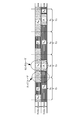
[0023]図1は、サイズC=3の協調クラスタを有するレイアウトを示している。説明のために便利なように、基地局が列挙されている。簡潔にするため、「クラスタ1」={1,2,3}、「クラスタ2」={4,5,6}、「クラスタ3」={7,8,9}のクラスタだけが、明示的に示されている。システムは、3つより多くの又は少ない(一般にははるかに多くの)クラスタを有することができることに留意されたい。
[0023] FIG. 1 shows a layout with a cooperative cluster of size C = 3. For convenience of explanation, base stations are listed. For the sake of brevity, only clusters with “
[0024]一実施形態では、クラスタ内のすべての基地局は、完全に協調する。すなわち、基地局のアンテナは、CNT個のアンテナを有する単一のMIMO送信機として効果的に動作し、基地局毎の合計電力制約を受ける。これは、実際には、各クラスタ内の基地局をクラスタコントローラ(プロセッサ)に接続することによって実施することができ、クラスタコントローラ(プロセッサ)は、新しい各時間フレームにおいて、クラスタ内のすべてのユーザ端末からすべてのチャネル状態情報測定を収集し、ダウンリンクにおいて同時にサービスされる1組のユーザと、対応するビーム形成ベクトル、電力割り当て、及びユーザ符号語とをスケジュールする。クラスタ合同処理は、各クラスタコントローラ(プロセッサ)当たり、限られた数の基地局しか含まないことに留意されたい。このようにして、非常に広いエリアにわたるカバレージを提供するために多数の基地局が使用される極限においてさえも(Nbs→∞)、システムの複雑さは抑制される。 [0024] In one embodiment, all base stations in the cluster are fully coordinated. That is, the base station antenna operates effectively as a single MIMO transmitter with CN T antennas and is subject to total power constraints per base station. This can actually be done by connecting a base station in each cluster to a cluster controller (processor), which in every new time frame, all user terminals in the cluster Collect all channel state information measurements from and schedule a set of users that are simultaneously serviced in the downlink and corresponding beamforming vectors, power allocations, and user codewords. Note that the cluster joint processing includes only a limited number of base stations for each cluster controller (processor). In this way, even in the limit where a large number of base stations are used to provide coverage over a very large area (N bs → ∞), the complexity of the system is suppressed.
[0025]図2のチャートは、クラスタの割り当てと、周波数サブチャネルに対する基地局電力割り当て係数(本明細書の目的では「電力マスク(power mask)」と呼ばれる)とを示している。この例では、ダウンリンクシステム帯域幅の全体が、3つの異なるクラスタリングレイアウトに対応する、3つのサブバンドに分割される。図1に示されるように、基地局1、2、3は、高い電力レベル(α)では周波数f=1の信号を送信し、中間のレベルの電力(β)では周波数f=2の信号を送信し、低い電力レベル(ω)では周波数f=3の信号を送信する。また、基地局4、5、6は、中間の電力レベル(β)では周波数f=3の信号を送信し、高い電力レベル(α)では周波数f=2の信号を送信し、低い電力レベル(ω)では周波数f=1の信号を送信し、基地局7、8、9は、高い電力レベル(α)では周波数f=3の信号を送信し、中間の電力レベル(β)では周波数f=1の信号を送信し、低い電力レベル(ω)では周波数f=2の信号を送信する。
[0025] The chart of FIG. 2 shows the allocation of clusters and base station power allocation factors (referred to as “power masks” for purposes herein) for frequency subchannels. In this example, the entire downlink system bandwidth is divided into three subbands corresponding to three different clustering layouts. As shown in FIG. 1,
[0026]一実施形態では、図1の基本レイアウトをシフトすることによって、重なり合った又はもつれ合った協調構造が獲得される。各シフトは、サブバンドに割り当てられる。この例では、シフトベクトルは、基準「クラスタ1」={1,2,3}内のセル1を(3つのシフトの1つによって)同じクラスタのセル1、2、3に移動することができるように選択される。一実施形態では、3つの重なり合うクラスタ構成は、Λbs 3内の3つの格子ベクトル(lattice vector)「シフト0」=0、「シフト1」=xbs(2)−xbs(1)、及び「シフト2」=xbs(3)−xbs(1)によって、図1の構成をシフトすることによって獲得される。例えば、「シフト1」構成のクラスタ1は、{2,4,7}であり、「シフト2」構成のクラスタ1は、{3,4,5}である。一実施形態では、基準構成(「シフト0」)のクラスタの境界の(トーラストポロジを法とする)剛性移動(rigid translation)によって、他のすべてのクラスタも同様に定義される。
[0026] In one embodiment, overlapping or entangled collaborative structures are obtained by shifting the basic layout of FIG. Each shift is assigned to a subband. In this example, the shift vector can move
[0027]図2に示されるように、各クラスタ構成は、サブバンドに関連付けられる。したがって、s=0、1、2として、「シフトs」によって表されるサブバンド上で送信されるすべての信号は、シフトsに対応するクラスタ構成に従ってクラスタ化される基地局が、合同で協調させる。そのような方式を実施するため、任意の1組の隣接する3つの基地局は、クラスタプロセッサに接続される必要がある。しかし、各コントローラ(プロセッサ)は、一度に3つの基地局だけを合同で扱う。したがって、一実施形態では、合同送信方式に必要な高速の相互接続は、ローカルリンクのみを含む。 [0027] As shown in FIG. 2, each cluster configuration is associated with a subband. Thus, assuming that s = 0, 1, 2, all signals transmitted on the subband represented by “shift s” are jointly coordinated by base stations clustered according to the cluster configuration corresponding to shift s. Let In order to implement such a scheme, any set of three adjacent base stations needs to be connected to a cluster processor. However, each controller (processor) handles only three base stations jointly at a time. Thus, in one embodiment, the high speed interconnect required for the joint transmission scheme includes only local links.
[0028]図2では、各クラスタサブバンドは、(この例では3つの)サブチャネルにさらに分割される。Fが、サブチャネルの総数を表すとし、Pが、すべての電力マスク係数を含む、次元がF×Nbsの非負配列を表すとする。例えば、図2は、F=9で、サイズが3のクラスタの例を動作させるためのPを(定性的に)示している。各基地局が、最大で公称値1の電力レベルで送信することができ、Pb,fが、基地局b及び周波数サブチャネルfの電力マスク係数を表すとして、基地局毎の合計電力制約が、
であることを課すと仮定する。クラスタの対称性が与えられた場合、一実施形態では、電力マスクは対称的である。この例では、係数α、β、ωが、Pの各列において繰り返される。一般に、Pのすべての要素が、厳格に正である場合、各クラスタは、システムの全帯域幅を利用する(完全周波数再利用)。一実施形態では、係数は、α≧β≧ω≧0となるように選択される。
[0028] In FIG. 2, each cluster subband is further divided into (in this example, three) subchannels. Let F denote the total number of subchannels, and let P denote a non-negative array of dimension F × N bs containing all power mask coefficients. For example, FIG. 2 shows (qualitatively) P for operating the example of a cluster with F = 9 and
Suppose that it imposes. Given cluster symmetry, in one embodiment, the power mask is symmetric. In this example, the coefficients α, β, ω are repeated in each column of P. In general, if all elements of P are strictly positive, each cluster utilizes the entire bandwidth of the system (full frequency reuse). In one embodiment, the coefficients are selected such that α ≧ β ≧ ω ≧ 0.
[0029]サイズC=3のクラスタと、電力割り当てを含む上記の例は、六角形格子の規則的なタイル張りを形成する任意のサイズCのクラスタと、任意の数のシフトに一般化することができる。ここでの目的では、1つのクラスタ構成のみを使用するシステムは、「シフトなし」と呼ばれる。本明細書では、あるセルを基本クラスタのC個のセルに移動するC個すべての可能なシフトベクトルに対応するC個のクラスタを使用するシステムは、「完全シフト」と呼ばれ、1<C’<Cとして、C’個のシフトを用いるシステムは、「部分シフト」と呼ばれる。図1及び図2の例において示される方式は、C=3の完全シフトである。 [0029] The above example involving size C = 3 clusters and power allocation generalizes to any size C clusters that form a regular tiled hexagonal lattice and any number of shifts. Can do. For purposes herein, a system that uses only one cluster configuration is referred to as “no shift”. In this document, a system that uses C clusters corresponding to all C possible shift vectors to move a cell to C cells of the base cluster is called a “perfect shift” and 1 <C A system that uses C shifts as' <C is called "partial shift". The scheme shown in the examples of FIGS. 1 and 2 is a full shift of C = 3.
[0030]図3は、通信システムにおいて送信電力を変更するためのプロセスの一実施形態のフロー図である。プロセスは、ハードウェア(例えば、専用ロジック、回路など)、(汎用コンピュータシステム若しくは専用マシンなどで作動する)ソフトウェア、又は両方の組み合わせを含むことができる処理ロジックによって実行される。 [0030] FIG. 3 is a flow diagram of one embodiment of a process for changing transmit power in a communication system. The process is performed by processing logic that may include hardware (eg, dedicated logic, circuitry, etc.), software (running on a general purpose computer system or a dedicated machine, etc.), or a combination of both.
[0031]図3を参照すると、プロセスは、処理ロジックが、単一の分散マルチアンテナ送信機として一緒に動作する隣接基地局からなる第1のクラスタによって使用される1組のチャネルを、サブチャネルに分割することによって開始する(処理ブロック301)。一実施形態では、チャネルは、周波数サブバンドに分割される。 [0031] Referring to FIG. 3, the process sub-channels a set of channels used by a first cluster of neighboring base stations whose processing logic operates together as a single distributed multi-antenna transmitter. (Processing block 301). In one embodiment, the channel is divided into frequency subbands.
[0032]サブバンドに分割した後、処理ロジックは、サブチャネル上で送信するための電力を、非一様なパターンで、第1のクラスタ内の各基地局に、第1のクラスタ内で及び他のクラスタにわたって合同で割り当てる(処理ブロック302)。一実施形態では、送信するための電力を割り当てるステップは、少なくとも2つのサブチャネルにおいて、第1のクラスタの基地局間で非一様な方法で各サブチャネル上において異なる電力レベルで送信するように、第1のクラスタ内の各基地局を設定するサブステップを含む。 [0032] After splitting into subbands, processing logic distributes power for transmission on the subchannel to each base station in the first cluster in a non-uniform pattern and in the first cluster. Assign jointly across other clusters (processing block 302). In one embodiment, the step of allocating power for transmission is to transmit at different power levels on each subchannel in a non-uniform manner between base stations of the first cluster in at least two subchannels. , Including a sub-step of configuring each base station in the first cluster.
[0033]その後、処理ロジックは、第1のクラスタ内の基地局のために送信をスケジュールし(処理ブロック303)、各サブチャネル上でワイヤレス信号を送信することを含む、第1のクラスタ内の基地局から1つ又は複数のユーザ端末への合同送信を生じさせ、それによって、各基地局及び各クラスタにおける送信電力は、電力協調パターンの事前割り当て電力レベルに従う(処理ブロック304)。 [0033] Processing logic then schedules transmissions for base stations in the first cluster (processing block 303) and includes transmitting wireless signals on each subchannel. A joint transmission from the base station to one or more user terminals occurs, whereby the transmission power at each base station and each cluster follows the pre-allocated power level of the power coordination pattern (processing block 304).
[0034]一実施形態では、プロセスは、各々が単一の分散マルチアンテナ送信機として一緒に動作する多くの基地局を異なるクラスタにシフトするステップと、クラスタ内の少なくとも2つの基地局がサブチャネルの少なくとも1つについて異なる送信電力レベルを有することを保証する方法で、送信電力協調パターンを異なるクラスタの各々に再割り当てするステップとをさらに含む。 [0034] In one embodiment, the process includes shifting a number of base stations, each operating together as a single distributed multi-antenna transmitter, to different clusters, and wherein at least two base stations in the cluster are subchannels. Reassigning the transmit power coordination pattern to each of the different clusters in a manner that ensures that at least one of the transmit power levels has a different transmit power level.
[0035]送信電力レベルパターンは、各チャネル上で、システマティックな方法で、送信電力変化を生じさせる。特に、与えられたクラスタ内の任意の与えられたチャネル上において、そのクラスタ内の及び近接性が一定のレベル内にあるすべてのクラスタにわたる関連する送信電力レベルは、スケジューリング/MIMO送信アルゴリズムによって選択された、そのクラスタ内のあるユーザに有利に働く結果を暗黙的にもたらす。クラスタ配備全体にわたる電力割り当てパターンは、各ユーザの信号対干渉及び雑音比(SINR)に影響を及ぼすことによって、これを達成する。与えられたチャネルにおいてユーザにサービスするコントローラにおける送信電力は、任意の与えられたユーザによって受信される大規模な信号レベルに影響を及ぼすが、近隣アンテナを制御するコントローラにおける関連する送信電力は、このユーザに対する干渉信号を生じさせ、そのユーザによって経験される大規模な集約干渉レベルを決定付ける。マルチセル配備にわたって一斉に適用される1組の電力レベルパターンを適切に(例えばオフライン最適化を介して)選択することによって、また例えば、周波数/時間スロットに応じて、1組の電力レベルパターンを周期的に繰り返すことによって、センタユーザとエッジユーザの間のスループットの乖離をより小さくしながら、高い合計レート配備を獲得することができる。 [0035] The transmit power level pattern causes a transmit power change on each channel in a systematic manner. In particular, on any given channel within a given cluster, the associated transmit power level within that cluster and across all clusters whose proximity is within a certain level is selected by the scheduling / MIMO transmission algorithm. It also implicitly results in favor of certain users in the cluster. The power allocation pattern across the cluster deployment accomplishes this by affecting each user's signal-to-interference and noise ratio (SINR). The transmit power at the controller serving a user on a given channel affects the large signal level received by any given user, but the associated transmit power at the controller controlling neighboring antennas is It produces an interference signal for the user and determines the large aggregate interference level experienced by that user. By appropriately selecting a set of power level patterns that are applied simultaneously across a multi-cell deployment (eg, via offline optimization) and, for example, depending on the frequency / time slot, By repeating the above, it is possible to obtain a high total rate deployment while further reducing the deviation in throughput between the center user and the edge user.
[0036]一実施形態では、技法は、実施の複雑さ、スケーラビリティ、及び性能の間のバランスをとるように試みる。パターンが適切に設計された場合、異なるコントローラによる異なるチャネル上でのスケジューリングに対して、ユーザの異なる(及びおそらくはまったく別個の)サブセットが有利になる。結果として、任意の与えられたチャネル内において各コントローラが作用するスケジューリングセットのサイズを制限することによって、各コントローラによって実行されるスケジューラ/MIMOアルゴリズムの複雑さを、(その性能を著しく損なうことなく)さらに低減させることができる。加えて、異なるチャネル内において各ユーザが経験しているSINRレベルに電力マスクが「バイアスをかける」ので、チャネルの小さなサブセット上でのみ、各ユーザはスケジューリングにおいて有利となる(スケジューリングについて検討されればよい)。あるチャネル内におけるスケジューリングについてユーザを検討するために、チャネル状態情報が必要とされることがある場合、そのような電力マスク変更は、かなりのシステム性能の悪化を招くことなく、システムのチャネルトレーニングオーバヘッドを低減させることも潜在的に可能である。 [0036] In one embodiment, the technique attempts to strike a balance between implementation complexity, scalability, and performance. If the pattern is properly designed, different (and possibly quite separate) subsets of users will be advantageous for scheduling on different channels by different controllers. As a result, the complexity of the scheduler / MIMO algorithm executed by each controller can be reduced (without significantly impairing its performance) by limiting the size of the scheduling set that each controller operates within any given channel. Further reduction can be achieved. In addition, since the power mask “biases” the SINR levels experienced by each user in different channels, each user is only advantageous in scheduling (if scheduling is considered). Good). If channel state information may be needed to consider users for scheduling within a channel, such a power mask change can cause system channel training overhead without significant system performance degradation. It is also possible to reduce.
[0037]本発明の実施形態は、マルチセル環境の下りリンク(forward link)における合同スケジューリング及び物理層送信のための方法を含む。一実施形態では、複数のコントローラが存在し、各々は、1組の送信アンテナからの送信を制御し、1組の送信アンテナは、1つのサイト又は複数のサイトに存在することができる。一実施形態では、広帯域マルチユーザ送信は、符号化多入力多出力(MIMO)/直交周波数分割多重化(OFDM)を使用して達成される。合同スケジューリング/MIMO送信は、チャネルと見なされる、OFDM送信における時間−周波数スロットのグループ上で実行される。MIMO送信技術は、シングルユーザMIMO又はマルチユーザMIMOとすることができる。 [0037] Embodiments of the present invention include a method for joint scheduling and physical layer transmission in a downlink in a multi-cell environment. In one embodiment, there are multiple controllers, each controlling transmission from a set of transmit antennas, and a set of transmit antennas can be present at one site or multiple sites. In one embodiment, wideband multi-user transmission is achieved using coded multiple input multiple output (MIMO) / orthogonal frequency division multiplexing (OFDM). Joint scheduling / MIMO transmission is performed on groups of time-frequency slots in OFDM transmission, which are considered channels. The MIMO transmission technique can be single-user MIMO or multi-user MIMO.
[0038]一実施形態によれば、時間−周波数スロット(スロットは与えられたOFDMブロック上の単一のOFDMトーンに対応する)は、チャネル上に(おそらくはグループとして)マッピングされる。各チャネル上で、各コントローラには、1組の送信アンテナサイト、与えられた送信電力限界、及びそのスケジューリング/MIMO送信アルゴリズムにおいて検討するユーザ端末のサブセットが割り当てられる。一実施形態では、各コントローラは、クラスタ内に存在する1つ又は複数の基地局を制御する。コントローラは、基地局内に存在すること、別個のユニットであること、又は複数の基地局にわたって分散することができる。 [0038] According to one embodiment, time-frequency slots (slots corresponding to a single OFDM tone on a given OFDM block) are mapped onto channels (possibly as a group). On each channel, each controller is assigned a set of transmit antenna sites, a given transmit power limit, and a subset of user terminals to consider in its scheduling / MIMO transmission algorithm. In one embodiment, each controller controls one or more base stations present in the cluster. A controller may reside within a base station, be a separate unit, or be distributed across multiple base stations.
[0039]本明細書で説明される本発明の実施形態のための構築ブロックは、以下の通りである。(a)サイトあたり1つ又は複数のアンテナを有する1組の送信アンテナサイト、(b)1組のコントローラ(例えば、1つ又は複数のクラスタ内の基地局)、(c)1組の仮想チャネル、及び時間的に変化する方法による、これらの仮想チャネルへの物理(時間/周波数)チャネルのマッピング、(d)アンテナ対コントローラの1組のマッピング、1つのマッピングは各仮想チャネルに関連付けられる、(e)1組のコントローラに割り当てられる1組の送信電力レベルパターン、コントローラにわたる1つのパターンは各仮想チャネルに関連付けられる、(f)スケジューリングのためのコントローラへのユーザの1組の分配、1つのユーザ−コントローラ分配は各仮想チャネルに関連付けられる、(g)合同スケジューリング/MIMO送信アルゴリズム。一実施形態では、MIMO送信アルゴリズムは、マルチユーザMIMOプリコーディングアルゴリズム(例えば、ブロックゼロ強制プリコーダ)である。別の実施形態では、MIMO送信アルゴリズムは、シングルユーザMIMOアルゴリズムである。ユーザ選択アルゴリズムは、比例公平性又は他の任意の基準に基づくことができる。任意の与えられたチャネル内で、合同スケジューリング/MIMO送信アルゴリズムは、与えられたスケジューリング基準に関して、各コントローラ上で(分配マップによって指定される1組のユーザ上で)別個に動作する。 [0039] The building blocks for the embodiments of the invention described herein are as follows. (A) a set of transmit antenna sites with one or more antennas per site, (b) a set of controllers (eg, base stations in one or more clusters), (c) a set of virtual channels Mapping of physical (time / frequency) channels to these virtual channels in a time-varying manner, (d) a set of antenna-to-controller mappings, one mapping associated with each virtual channel ( e) a set of transmit power level patterns assigned to a set of controllers, one pattern across the controllers is associated with each virtual channel, (f) a set of distribution of users to the controller for scheduling, one user A controller distribution is associated with each virtual channel, (g) joint scheduling / MI O transmission algorithm. In one embodiment, the MIMO transmission algorithm is a multi-user MIMO precoding algorithm (eg, a block zero forced precoder). In another embodiment, the MIMO transmission algorithm is a single user MIMO algorithm. The user selection algorithm can be based on proportional fairness or any other criteria. Within any given channel, the joint scheduling / MIMO transmission algorithm operates separately on each controller (on the set of users specified by the distribution map) for the given scheduling criteria.
2ステージ動作
[0040]一実施形態では、基地局協調パターン及び送信電力マスクの変更は、2ステージ動作として実施される。以下の2ステージ動作は、コントローラに関して説明される。これらのコントローラは、1つ又は複数のアンテナを制御する基地局の一部とすることができる。
2-stage operation
[0040] In one embodiment, the base station coordination pattern and transmission power mask change is implemented as a two-stage operation. The following two-stage operation is described with respect to the controller. These controllers can be part of a base station that controls one or more antennas.
[0041]ステージ1において、ステージ2で各コントローラによって使用される1組のパラメータが生成される。これらのパラメータは、(仮想)チャネルの番号1、2、...、Fによってインデックス付けされるルックアップテーブルに保存される。インデックスがfのチャネルエントリが与えられると、ルックアップテーブルは、各コントローラによって使用される、合同スケジューリング/MIMO送信のためのパラメータを提供する。一実施形態では、ルックアップテーブルがひとたび生成されると、それがコントローラにプッシュされる。一実施形態では、ルックアップテーブル全体を各コントローラにプッシュすることができるが、そのコントローラの動作に関係するパラメータのサブセットだけが、各コントローラにプッシュされる。ステージ1は、例えば、オフライン最適化、又はより一般に、ステージ2におけるスケジューリング/送信動作よりも通常はかなり長い時間スケールで実行される最適化など、1回限りの計算とすることができる。
[0041] In
[0042]ステージ2は、各コントローラによって実行される合同スケジューリング/送信動作に対応する。一実施形態では、1組のコントローラが、この動作を並列に実行する。各物理チャネル内で、各コントローラは最初に、ルックアップテーブル内でコントローラが対応する実際の「仮想チャネル」を識別し、ルックアップテーブルから対応するパラメータをフェッチする。一実施形態では、これらのパラメータは、(i)このチャネル内でコントローラがそれから送信する1組の送信アンテナ及びサイト、(ii)このチャネルについてコントローラに課される送信電力制約、(iii)コントローラの合同スケジューリング/MIMO送信アルゴリズムによってスケジューリングについて検討される必要がある1組のユーザを含む。
[0042]
[0043]一実施形態では、各ユーザのための(例えば、スケジューリングアルゴリズムにおけるユーザ重みの更新バージョンを含む)リアルタイムスケジューリングパラメータの1つ又は複数のリポジトリが存在する。与えられたチャネル内におけるスケジューリングのためにコントローラが検討するすべてのユーザについての関連する重み/パラメータをコントローラが入手できることを保証するために、必要な場合は、各コントローラはリポジトリにアクセスする。その結果、合同スケジューリング/送信アルゴリズムが実施され、ユーザのサブセットが選択されて、サービスされ、サービス対象セット内のすべてのユーザの重みを更新するための情報が、リポジトリにプッシュされる。一実施形態では、更新は、各コントローラにおいてローカルに起こり、その場合、コントローラのユーザスケジューリングセットのための更新された重み/パラメータが、関連するリポジトリにプッシュされる。別の実施形態では、サービスされたユーザ及びそれらのレートを要約したパラメータの組を、リポジトリにプッシュバックすることができ、更新される重み/パラメータが計算され、保存される。 [0043] In one embodiment, there are one or more repositories of real-time scheduling parameters (including, for example, an updated version of user weights in the scheduling algorithm) for each user. Each controller accesses the repository, if necessary, to ensure that the controller has access to relevant weights / parameters for all users that the controller considers for scheduling within a given channel. As a result, a joint scheduling / transmission algorithm is implemented, a subset of users is selected, serviced, and information for updating the weights of all users in the serviced set is pushed to the repository. In one embodiment, the update occurs locally at each controller, in which case the updated weights / parameters for the controller's user scheduling set are pushed to the associated repository. In another embodiment, a set of parameters summarizing served users and their rates can be pushed back to the repository, and updated weights / parameters are calculated and stored.
[0044]以下の代表的な高水準コードは、ステージ2において1例のコントローラ上で実行される動作の論理セットを示している。
1)(ステージ1において生成された)スケジューリング/送信パラメータルックアップテーブルのコントローラのセクションを獲得する。
2)k=1、...、Kとして、各物理チャネルkに対して以下を実行する。
a.(ルックアップテーブルを介して、又は決定論的な方法で)物理チャネルkを仮想チャネルに関連付ける。f=f(k)がこの仮想チャネルの関連インデックスを表すとする。
b.(論理ステップ1で獲得された)ルックアップテーブルからチャネルインデックスfに関連付けられたエントリをフェッチする。
c.ルックアップテーブルエントリ内に列挙されたスケジューリングセット内のすべてのユーザのためのリアルタイムスケジューリングパラメータをリポジトリに要求する。(この列挙は暗黙的とすることができ、例えば、公称SINRが与えられた範囲内にあるユーザなど、ルックアップテーブルエントリはユーザの組を間接的に表すことができる)。
d.リポジトリからのリアルタイムスケジューリングパラメータを使用して、このユーザの組に対して合同スケジューリング/送信アルゴリズムを実行する。1組のアンテナから、チャネルインデックスfを有するルックアップテーブルエントリによって表される送信電力を用いて、送信が実行される。
e.スケジューリングについて検討されたユーザの組のリアルタイムスケジューリングパラメータを更新するのに必要とされる情報を、リポジトリにプッシュする。
[0044] The following representative high-level code illustrates a logical set of operations performed on an example controller in
1) Get the controller section of the scheduling / transmission parameter lookup table (generated in stage 1).
2) k = 1,. . . , K, for each physical channel k:
a. Associate physical channel k with a virtual channel (via a look-up table or in a deterministic manner). Let f = f (k) denote the associated index of this virtual channel.
b. Fetch the entry associated with channel index f from the lookup table (obtained in logic step 1).
c. Requests the repository for real-time scheduling parameters for all users in the scheduling set listed in the lookup table entry. (This enumeration can be implicit, for example, a lookup table entry can indirectly represent a set of users, such as users whose nominal SINR is within a given range).
d. A real-time scheduling parameter from the repository is used to perform a joint scheduling / transmission algorithm for this set of users. Transmission is performed from a set of antennas using the transmit power represented by the look-up table entry with channel index f.
e. The information needed to update the real-time scheduling parameters of the set of users considered for scheduling is pushed to the repository.
[0045]概略的なステップ2dでは、すなわち、合同スケジューリング/送信アルゴリズムは、あらゆるチャネル上で実行されるが、上記の動作2c及び2eは、合同スケジューリングアルゴリズムを1回使用するたびに生じる必要はない。 [0045] In schematic step 2d, ie the joint scheduling / transmission algorithm is performed on every channel, the above operations 2c and 2e need not occur each time the joint scheduling algorithm is used once. .
マッピングテーブルの例
[0046]以下で説明される表は、コントローラにどのように送信アンテナサイト、送信電力、及びスケジューリング対象のユーザの組を割り当てるかを示す、マッピングの代表的な例を提供している。例のすべてにおいて、時間−周波数スロットのグループが、周期的に時間変化する方式で、1組の「チャネル」にマッピングされると仮定される。その場合、そのような各チャネルにおける、このチャネル(時間−周波数スロットのグループ)上で各コントローラによって使用される送信電力レベル、各コントローラによって制御されるアンテナサイト、コントローラが各場合にスケジュールするサブセットを各コントローラがそれから選択するユーザのサブセットを決定するために、各例において提供されるマッピングが使用されると仮定される。具体的には、各チャネル内で、マッピングは、与えられたコントローラによってどのアンテナが制御されるか、信号送信のためにそのコントローラに利用可能な総電力、合同スケジューリング−送信アルゴリズムが実施されるユーザのサブセットを列挙する。
Mapping table example
[0046] The table described below provides a representative example of how to assign a transmit antenna site, transmit power, and a set of scheduled users to a controller. In all of the examples, it is assumed that groups of time-frequency slots are mapped to a set of “channels” in a time-varying manner in a periodic manner. In that case, for each such channel, the transmit power level used by each controller on this channel (group of time-frequency slots), the antenna sites controlled by each controller, and the subset that the controller schedules in each case. It is assumed that the mapping provided in each example is used to determine the subset of users that each controller then selects. Specifically, within each channel, the mapping is based on which antenna is controlled by a given controller, the total power available to that controller for signal transmission, and the user on which the joint scheduling-transmission algorithm is implemented. List a subset of
[0047]説明を簡潔にするため、1次元配備の例が使用され、有限の数のアンテナサイトが、循環する線分にわたって一様に配置され、すなわち、線分の左端は、線分の右端と同一点であると見なされる。M個のアンテナサイトが、S0、S1、...、SM−1として列挙される。「i」が0又はM−1に等しい場合を除いて、Siの左隣及び右隣のアンテナサイトは、それぞれSi−1及びSi+1である。具体的には、構成の循環性のため、S0の左隣及び右隣は、それぞれSM及びS1であり、SM−1の左隣及び右隣は、それぞれSM−2及びS0である。 [0047] For the sake of brevity, an example of a one-dimensional deployment is used and a finite number of antenna sites are evenly distributed over the circulating line segment, ie, the left end of the line segment is the right end of the line segment Is considered the same point. M antenna sites are denoted by S 0 , S 1 ,. . . , S M-1 . Except where "i" is equal to 0 or M-1, left side and right side of the antenna site S i is S i-1 and S i + 1, respectively. Specifically, due to the cyclic nature of the configuration, the left and right neighbors of S 0 are S M and S 1 , respectively, and the left and right neighbors of S M-1 are S M−2 and S 1 , respectively. 0 .
[0048]任意の与えられたチャネル内では、原理的に、スケジューリングのためにどのコントローラにも割り当てられないユーザが存在する場合、性能上の損失が生じる。しかし、任意の与えられたコントローラ上でのより小さな組のユーザの合同スケジューリング/MIMO送信は、複雑さ及び必要とされるチャネル状態情報のオーバヘッドの著しい低減をもたらすことができる。これは、MU−MIMOが、利用されるMIMO送信方式である場合に特に当てはまる。さらに、チャネル及び空間(又は信号対干渉レベル)上でスケジューリング対象のユーザの組を慎重に制限することによって、またチャネル及びコントローラ上で送信電力レベルパターンを慎重に選択することによって、協調及びスケジューリング/MIMO送信アルゴリズムにおいて、はるかに低い複雑さオーバヘッドを有する、高性能のシステムを設計することができる。 [0048] Within any given channel, in principle there is a performance loss if there are users that are not assigned to any controller for scheduling. However, joint scheduling / MIMO transmission of a smaller set of users on any given controller can result in a significant reduction in complexity and overhead of required channel state information. This is especially true when MU-MIMO is the MIMO transmission scheme used. In addition, by carefully limiting the set of scheduled users on the channel and space (or signal-to-interference level), and by carefully selecting the transmit power level pattern on the channel and controller, coordination and scheduling / A high performance system with much lower complexity overhead can be designed in the MIMO transmission algorithm.
コントローラ当たり1つのアンテナサイト
[0049]図4は、4つのアンテナサイト(S0、...、S3)の各々を制御する4つのコントローラ(C0、...、C3)についての、2チャネル電力/ユーザスケジューリング割り当てパターンを示している。図4を参照すると、Uiは、アンテナサイトSiに「関連付け」られたすべてのユーザを表す。簡潔にするため、この関連付けは、距離ベース(すなわち経路損失ベース)であると仮定する。より一般的には、この関連付けは、大規模な信号対干渉及び雑音電力比(SINR)に基づくことができる。Uiの2つのサブセットが、すなわち、ユーザの組Ui,C及びUi,Eが存在する。組Ui,Cは、Siに十分に近い(したがって本明細書では「センタユーザ」と呼ばれる)ユーザのサブセットに対応し、組Ui,Eは、Siから十分に遠い(したがって本明細書では「エッジユーザ」と呼ばれる)ユーザのサブセットに対応する。(図では、これらの2つの組は重なり合わずに示されているが)Ui,C及びUi,Eは、重なり合う組とすることができることに留意されたい。1つの究極においては、Ui,Eは、例えば、組Uiの全体に対応することができる。一般に、「センタ」ユーザと「エッジ」ユーザの分割は、距離に基づかずに、むしろ公称の大規模なSINRレベルに基づくことができることにも留意されたい。1つのそのような戦略によれば、すべてのサイトに共通する公称送信電力が与えられた場合、Ui内のどのユーザも、平均公称大規模SINRがある閾値を超えた場合には、サイトのセンタグループに含まれ、公称SINRレベルがある閾値を下回る場合には、エッジグループに含まれる。
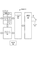
1 antenna site per controller
[0049] FIG. 4 shows a two-channel power / user scheduling allocation pattern for four controllers (C0, ..., C3) controlling each of the four antenna sites (S0, ..., S3). ing. Referring to FIG. 4, U i represents all users “associated” with antenna site S i . For simplicity, this association is assumed to be distance based (ie path loss based). More generally, this association can be based on large signal to interference and noise power ratio (SINR). There are two subsets of U i , namely the user sets U i, C and U i, E. The set U i, C corresponds to a subset of users sufficiently close to S i (hence referred to herein as “center users”), and the set U i, E is sufficiently far from S i (hence the specification). Corresponds to a subset of users (called “edge users”). Note that U i, C and U i, E can be overlapping sets (although these two sets are shown non-overlapping in the figure). In one ultimate, U i, E can correspond to the entire set U i , for example. It should also be noted that in general, the division of “center” users and “edge” users can be based on nominal large SINR levels rather than being based on distance. According to one such strategy, given a nominal transmit power common to all sites, if any user in U i exceeds a certain nominal large SINR threshold, If it is included in the center group and the nominal SINR level is below a certain threshold, it is included in the edge group.
[0050]偶数(奇数)セル/コントローラのUi,E内のユーザは、チャネル1(チャネル2)でサービスされ、Ui,C内のユーザは、他方のチャネルでサービスされる。Ui,CとUi,Eは、互いに素でもよく、又は互いに素でなくてもよいことに留意されたい。例えば、Ui,E=Uiであるが、Ui,C⊂Uiである場合、エッジユーザは、両方のチャネル上でスケジュールすることができ、センタユーザは、関連するコントローラ送信電力が低い場合にのみ、スケジュールすることができる。代替として、Ui,C=Uiであるが、Ui,E⊂Uiである場合、センタユーザは、両方のチャネル上でスケジュールすることができ、エッジユーザは、関連するコントローラ送信電力が高い場合にのみ、スケジュールすることができる。 [0050] Users in U i, E of even (odd) cells / controllers are served on channel 1 (channel 2) and users in U i, C are served on the other channel. Note that U i, C and U i, E may or may not be disjoint. For example, if U i, E = U i but U i, C ⊂U i , the edge user can schedule on both channels and the center user has a low associated controller transmit power Can only be scheduled. Alternatively, if U i, C = U i , but U i, E ⊂U i , the center user can schedule on both channels and the edge user will have the associated controller transmit power Can only be scheduled when it is high.
[0051]表1は、図4の例のための1例のルックアップテーブルの説明を含んでいる。ルックアップテーブルは、2つのチャネル上におけるコントローラにわたる送信アンテナ/送信電力/ユーザセット合同パターン割り当ての説明を提供する。一実施形態では、チャネルは、同じOFDMブロック上の異なるOFDMトーン、又は異なるOFDMブロックの同じトーンに対応する。送信電力PL及びPHは、センタユーザとエッジユーザに対するレート割り当てを最適化するように選択され、総電力制約Pに従う、すなわち、(PL+PH)/2=Pである、適切に事前選択された電力レベルに対応する。エッジユーザに提供されるレートを改善するには、PL及びPHは、エッジユーザがサービスされるスロット(チャネル)の間、エッジユーザの公称SINRレベルが好ましく(すなわち十分に大きく)なるように選択されなければならないことに留意されたい。それらのチャネルでは、エッジユーザの信号電力は、PHを増大させることによって高めることができ、干渉電力は、PLを減少させることによって低減することができるので、PH=PL=Pの場合のエッジスループットを改善するために、PH>PLとする。結果として、任意の与えられたチャネル上では、スケジューリングについて検討されるすべてのエッジユーザに高い電力レベルが割り当てられ、エッジユーザに最も近い干渉サイトは、低い電力で送信する。この不均衡な電力割り当ての試みは、送信のためにすべての基地局によって等しい送信電力が使用される場合に存在する、センタユーザとエッジユーザの間の大きな公称SINRレベルの差を釣り合わせることによって、システム全体の公平性を改善する。 [0051] Table 1 includes a description of an example lookup table for the example of FIG. The look-up table provides a description of transmit antenna / transmit power / user set joint pattern assignment across controllers on two channels. In one embodiment, the channels correspond to different OFDM tones on the same OFDM block or to the same tone of different OFDM blocks. The transmit powers P L and P H are selected to optimize the rate allocation for center users and edge users and are subject to the total power constraint P, ie (P L + P H ) / 2 = P Corresponds to the selected power level. To improve the rate offered to edge users, P L and P H are such that the nominal SINR level of the edge user is preferred (ie, sufficiently large) during the slot (channel) in which the edge user is serviced. Note that it must be selected. In those channels, the signal power of the edge user can be enhanced by increasing the P H, the interference power can be reduced by reducing the P L, the P H = P L = P In order to improve edge throughput in this case, P H > P L. As a result, on any given channel, all edge users considered for scheduling are assigned a high power level, and the interfering site closest to the edge user transmits with low power. This unbalanced power allocation attempt is by balancing the large nominal SINR level differences between the center user and the edge user that exist when equal transmit power is used by all base stations for transmission. , Improve the fairness of the whole system.
[0052]一実施形態では、最適化された(PH,PL)ペアは、オフライン最適化を介して決定される。PH及びPLは、それぞれエッジユーザ及びセンタユーザに任意の与えられたコントローラの基地局が任意の与えられたチャネル上で送信するために許容される最大送信電力である。スケジュールされるユーザの間へのその電力の割り当ては、適切なスケジューリングアルゴリズムに委ねられる。
[0053]上記の割り当てが、F>2として、F個のチャネルが利用される場合に容易に一般化されることは、当業者には容易に明白である。特に、P1、P2、...、PFが、Pi<Pi+1で、(1/F)ΣfPf=Pである、電力レベルを表すとする。{Ui,1,Ui,2、...、Ui,F}が、それらの結びがUiである、集合Uiの部分集合を表すとする。さらに、部分集合Ui,1及びUi,Fが、セルの「センタ」及び「エッジ」にいるユーザを表すと仮定し、fがf=1からf=Fに増加するにつれて、アンテナサイトSiから次第に遠ざかるユーザを含む部分集合Ui,fが生成されると仮定する。その場合、表2は、先の2チャネルの例を一般化したFチャネルバージョンを示している。やはり、電力割り当ての組{Pi}は、オフライン最適化を介して決定される。
コントローラ当たり2つ(以上)のアンテナサイト
[0054]以下の3つの代表的な例は、8個の送信アンテナと4個のコントローラを有する循環線形配列を含むワイヤレスシステムに関する。これらのケースでは、単一のコントローラが、複数の(このケースでは2つの)アンテナサイトにおいてアンテナを制御する。元の例と同様に、Ui,Cは、Ui内のユーザの内Siに最も近いユーザのサブセットを表す。しかし、このケースでは、「エッジ」ユーザの組は、2つの組に、すなわち、Ui,L及びUi,R(それぞれ「左」エッジグループ及び「右」エッジグループ)に分割される。やはり、グループはそれらの距離及びSiに対する相対ロケーションに関して分割されたが、より関連性のある大規模な信号対干渉レベルをユーザ分配のために使用できることに留意されたい。例えば、ユーザは、右(「左」)近隣送信アンテナサイトからのその公称集約干渉レベルが一定の閾値を超えた場合、コントローラによって、「右」(「左」)エッジグループに含めることができる。ユーザを複数のグループに含めることができることにも留意されたい。
2 (or more) antenna sites per controller
[0054] The following three representative examples relate to a wireless system including a circular linear array with 8 transmit antennas and 4 controllers. In these cases, a single controller controls the antennas at multiple (two in this case) antenna sites. Similar to the original example, U i, C represents the subset of users closest to S i among the users in U i . However, in this case, the “edge” user set is divided into two sets, ie, U i, L and U i, R (“left” edge group and “right” edge group, respectively). Again, it should be noted that although the groups were divided with respect to their distance and relative location to S i , a more relevant large signal-to-interference level can be used for user distribution. For example, a user can be included in a “right” (“left”) edge group by a controller if its nominal aggregate interference level from a right (“left”) neighboring transmit antenna site exceeds a certain threshold. Note also that a user can be included in multiple groups.
[0055]図5に示されるこれらのケースの第1の例は、どのコントローラによって制御されるアンテナサイトもチャネルに応じて変化しないパターンについて考察し、これは図4の例の自然な拡張である。すなわち、図5は、表2に関連する、3つのチャネル電力/ユーザスケジューリング割り当てパターンを示している。図5を参照すると、4つのコントローラ(C0、...、C3)が存在し、各々が、2つのアンテナサイトを制御する(コントローラC3と、それが制御するサイトS6及びS7は図に示されていない)。3つの電力レベルP1、P2、P3が存在する。「センタ」ユーザの組(Ui,C)と、「左エッジ」ユーザの組(Ui,L)と、「右エッジ」ユーザの組(Ui,R)の、ユーザの3つの組が、アンテナサイトSiに関連付けられたユーザの組Uiから生成される。すべての「センタ」ユーザは、チャネル3内にスケジュールされる。そのチャネルでは、すべてのコントローラに同じ送信電力(P3)が割り当てられる。チャネル1及びチャネル2は、エッジセット内のユーザにサービスする。これらのチャネルでは、コントローラ送信電力割り当ては、「奇数」コントローラが電力P1(P2)を使用する場合、偶数コントローラが電力P2(P1)を使用するように、P1とP2の間で変更される(P1>P2とする)。また、コントローラは、電力P1(P2)で送信する場合、その2セルクラスタの「エッジ」(「センタ」)にいるエッジセットのユーザにサービスする。
[0055] The first example of these cases shown in FIG. 5 considers a pattern where the antenna site controlled by any controller does not change with channel, which is a natural extension of the example of FIG. . That is, FIG. 5 shows three channel power / user scheduling assignment patterns associated with Table 2. Referring to FIG. 5, there are four controllers (C0, ..., C3), each controlling two antenna sites (controller C3 and the sites S6 and S7 it controls are shown in the figure. Not) There are three power levels P 1 , P 2 , P 3 . There are three sets of users: a “center” user set (U i, C ), a “left edge” user set (U i, L ), and a “right edge” user set (U i, R ). , Generated from the set of users U i associated with the antenna site S i . All “center” users are scheduled in
[0056]表3は、1例の3チャネル送信サイト/送信電力/ユーザセットパターン割り当てを提供する。電力は、(P1>P2)として、(P1+P2+P3)/3=Pを満たし、一般に、オフラインで決定される。
[0057]次の2つの表は、各コントローラによって制御されるアンテナサイトがチャネルに応じて変化する(代替として時間に応じて変化してもよい)、2つの例を考察している。図6に示される第1の例では、各コントローラに割り当てられる送信電力は、チャネル毎に変化しない。図6を参照すると、4つのコントローラ(C0、...、C3)の各々は、各チャネル内において2つのアンテナサイトを制御する。コントローラによって制御されるアンテナサイトは、2つのチャネルの間で変化する。送信電力は、チャネル毎に変化しない。アンテナサイトSiに関連付けられるユーザの組Uiは、センタユーザ(Ui,C)とエッジユーザ(Ui,E)に分割され、「エッジ」ユーザは、2つの組、Ui,LとUi,R(それぞれ「左」エッジグループ及び「右」エッジグループ)にさらに分割される。アンテナサイトが配置される線分は循環する。しかし、あるユーザは、チャネルの1つの上でのみ(あるコントローラによって)スケジューリングについて検討することができ、他のユーザは、複数のチャネルの上でスケジューリングについて検討することができる。これは、表4に示される例におけるセンタユーザ(アンテナサイトに最も近いユーザ)の場合である。この例では、センタユーザは、2つのチャネル上でスケジュールすることができるが、エッジユーザは常に、1つのチャネル上でスケジュールされる。しかし、スケジュールされるエッジユーザは、近隣アンテナサイトの両方がそれらのコントローラによって制御される場合に、スケジューリングについて検討されることに留意されたい。
[0058]図7に示される最後の例では、送信アンテナサイト、送信電力、及び任意の与えられたコントローラによってスケジュールされるユーザの組はすべて、チャネルに応じて変更される。図7を参照すると、コントローラ(C0、...、C3)の各々は、2つのアンテナサイトを制御し、各コントローラによって制御されるサイトと、それらの送信電力レベルは、チャネルに応じて変化する。図7に示されるように、2つの異なるシフトと、シフト当たり2つの電力割り当てが存在する。すべての組み合わせからなる組が、表5に示される4チャネル電力/BS対コントローラ関連付けで説明されている。
その他の拡張
[0059]本明細書で説明されたパターン割り当てには多くの直接的な拡張が存在する。例えば、表5では、ただ2レベルの送信電力粒度が考えられたが、この手法は、F>2として、Fレベル粒度に容易に拡張することができる。一般に、電力割り当てを選択するための厳格な規則は設定されないことに留意されたい。先の例は、最も高い電力レベルが1つのコントローラで使用される場合、その近隣コントローラでは最も低い電力レベルが使用されることを示唆しているように見えるが、オフラインで生成される電力割り当てパターンは、この示唆に従う必要はない。
Other extensions
[0059] There are many direct extensions to the pattern assignment described herein. For example, in Table 5, only two levels of transmission power granularity were considered, but this approach can be easily extended to F level granularity, with F> 2. Note that in general, no strict rules are set for selecting power allocation. The previous example seems to suggest that if the highest power level is used on one controller, the neighboring controller will use the lowest power level, but the power allocation pattern generated off-line Do not have to follow this suggestion.
[0060]加えて、表5の例では、各コントローラは、一度に2つのアンテナサイトを制御するだけであり、ただ2つのパターンの制御の間で振動する。任意の時点で、より多くのアンテナサイトを制御することができ、アンテナサイトのより多くのサブセットを制御するために、コントローラを割り当てることができる。図10、図11、及び図12は、サイズが3のクラスタを有するそのような例を示している。コントローラは、C0〜C3として指定され、基地局は、S0〜S11として指定される。図10に示される実施形態では、2つのチャネルが利用される。各コントローラは、両方のチャネル上で基地局の同じ組に関連付けられる。各クラスタ内のセンタ基地局は、常に電力PMで送信する。各クラスタ内のエッジ基地局は、一方のチャネル上では電力PLで送信し、他方のチャネル上では電力PHで送信する。さらに、与えられたチャネル(1又は2)においてクラスタのエッジ基地局が電力PHで送信する場合、同じチャネルにおける2つの近隣クラスタのエッジ基地局は、電力PLで送信するように設定される。結果として、PH>PLを仮定すると、各クラスタにおけるカバレージは、チャネル1とチャネル2とでは違いがある。図の影付きの領域は、ユーザがスケジュールされるカバレージエリアがチャネル及びクラスタに応じてどのように変化するかを定性的に示唆することを意図している。具体的には、チャネル内のより濃いエリアは、与えられたロケーションにいるユーザがそのチャネル上でスケジュールされる可能性がより高いことを示唆し、より薄い影付き領域は、これらのエリア内のユーザがスケジュールされる可能性が低いことを示唆する。
[0060] In addition, in the example of Table 5, each controller only controls two antenna sites at a time and oscillates between only two patterns of control. At any given time, more antenna sites can be controlled and controllers can be assigned to control more subsets of antenna sites. 10, 11 and 12 show such examples having clusters of
[0061]図11は、図10に示された例の変形である別の実施形態を示している。やはり、各コントローラは、両方のチャネル上で同じ組の基地局に関連付けられ、各クラスタ内のセンタ基地局は、常に電力PMで送信する。さらに、与えられたチャネル(1又は2)においてクラスタの左エッジ基地局の電力がPHに等しい場合、左側の近隣クラスタの右エッジ基地局の電力は、同じチャネル上でPLに設定される。図10と同様に、図の影付き領域は、PH>PLと仮定して、ユーザがスケジュールされるカバレージエリアがチャネル及びクラスタに応じてどのように変化するかを定性的に示唆することを意図している。 [0061] FIG. 11 shows another embodiment that is a variation of the example shown in FIG. Again, each controller associated on both channels at the same set of base stations, the center base station in each cluster is always transmitted at a power P M. Furthermore, the power of a given channel (1 or 2) in clusters left edge base station is equal to P H, the power of the right edge BS of the left neighboring clusters is set to P L on the same channel . Similar to FIG. 10, the shaded area in the figure qualitatively suggests how the coverage area where the user is scheduled will vary depending on the channel and cluster, assuming P H > P L. Is intended.
[0062]図12は、サイズが3のクラスタを有する3つのチャネルを含む別の関連実施形態を示している。クラスタは、3つのチャネルに応じて変更される(完全シフトシステムを実施する)。各チャネル内で、センタ基地局は、電力PMで送信し、エッジ基地局は、電力PLで送信する。 [0062] FIG. 12 illustrates another related embodiment that includes three channels having clusters of size three. The cluster is changed according to three channels (implementing a full shift system). Within each channel, the center base station transmits with power P M and the edge base station transmits with power P L.
[0063]2次元セルラレイアウトを含む関連実施形態を容易に設計することができる。2次元六角形タイプセル構成を含む一実施形態では、各コントローラは、一度に7つのアンテナサイトを制御する。最初に、コントローラとアンテナサイトの間の関連付けが固定され、各コントローラが「センタ」サイトとその6つの近隣サイトを制御する、静的なアンテナ割り当てケースについて考える。F個の異なる電力レベルパターンの全部がコントローラにわたって利用される場合、F個のチャネルの全部を利用して、関連するパターン割り当てを表すことができる。各コントローラ/送信アンテナサイト関連付けがチャネルに応じて変化する、より動的な設定を考えることができる。例えば、各コントローラは、7つの可能な「7送信アンテナサイト」クラスタ構成の間で振動することができるコントローラによって制御されるクラスタ内の中央アンテナサイトは、与えられたサイトとその6つの第1層近隣サイトの間で周期的に変更される。その場合、各アンテナサイト/コントローラ割り当てについて、F個の異なる電力レベルパターンがコントローラにわたって利用されると仮定すると、7F個のチャネルの全部を利用して、関連するパターン割り当てを表すことができる。先のケースと同様に、7F個のチャネルのためのルックアップテーブルパラメータは、オフラインで生成することができる。 [0063] Related embodiments involving a two-dimensional cellular layout can be readily designed. In one embodiment that includes a two-dimensional hexagonal type cell configuration, each controller controls seven antenna sites at a time. First, consider a static antenna allocation case where the association between the controller and antenna sites is fixed and each controller controls the “center” site and its six neighboring sites. If all of the F different power level patterns are utilized across the controller, all of the F channels can be utilized to represent the associated pattern assignment. More dynamic settings can be considered where each controller / transmit antenna site association varies with channel. For example, each controller can be oscillated between seven possible “7 transmit antenna site” cluster configurations, and the central antenna site in a cluster controlled by a controller is a given site and its six first layers. Changed periodically between neighboring sites. In that case, assuming that F different power level patterns are utilized across the controller for each antenna site / controller assignment, all of the 7F channels can be utilized to represent the associated pattern assignment. Similar to the previous case, the look-up table parameters for 7F channels can be generated off-line.
[0064]ユーザのスケジューリングは、チャネル(又は協調パターン)にわたって合同で実行される。任意の与えられたチャネル上では、ユーザの互いに素の組を異なるコントローラに割り当てるが、各スケジューリングアルゴリズムは、各コントローラ上で独立に実行される。しかし、各コントローラは、任意の与えられたチャネル内では他のコントローラとは独立にユーザをスケジュールするが、マルチセル配備にわたるユーザのレートは、依然として結合させることができる。具体的には、与えられたユーザが異なるチャネル上では異なるコントローラに割り当てられる配備が使用される場合、ユーザのスケジューリングは、コントローラにわたって間接的に結合される。これらのケースでは、各チャネル内で、与えられたコントローラについて、ユーザ選択が独立に行われるとしても、チャネル(又は協調パターン)にわたって共有される情報が存在し、この情報が、コントローラによって利用されて、そのチャネルの各々のユーザ選択で使用されるパラメータを更新する。この情報は、各ユーザに関連付けられた重み、ユーザが最後にスケジュールされた時、及び/又は他の関連スケジューリングパラメータとすることができる。 [0064] User scheduling is performed jointly across channels (or coordination patterns). On any given channel, each user's disjoint set is assigned to a different controller, but each scheduling algorithm is executed independently on each controller. However, although each controller schedules users independently of other controllers within any given channel, the user's rates across multi-cell deployments can still be combined. Specifically, if a deployment is used where a given user is assigned to a different controller on a different channel, the user's scheduling is indirectly coupled across the controllers. In these cases, within each channel, there is information shared across the channel (or coordination pattern) for a given controller, even if user selection is made independently, and this information is used by the controller. Update the parameters used in the user selection for each of the channels. This information may be the weight associated with each user, when the user was last scheduled, and / or other related scheduling parameters.
[0065]マルチセル配備にわたるユーザのレート間の結合は、コントローラへの送信アンテナの静的な割り当てが存在する場合であっても生じることができる。例えば、そのようなユーザ−レート結合は、コントローラにわたって変化する送信電力レベルパターンを使用することによって、また例えば「エッジ」ユーザを異なるチャネルに応じて異なるコントローラに(スケジューリングのために)思慮深く関連付けことによって引き起こすことができる。1つのそのような例が、図8に示されている。アンテナ対コントローラ関連付けは、図4の例におけるものと同じである。図8を参照すると、各コントローラCn(C0、...、C3だけが示されている)は、1つのアンテナサイトSnを制御する。各コントローラによって使用される電力レベルは、2つのチャネル上で、低い電力(PL)と高い電力(PH)の間で変更される。図では、「センタ」ユーザ(すなわち、アンテナサイトに十分に近いユーザ、又は十分に高い公称SINRを有するユーザ)は常に、同じコントローラによってサービスされるが、「エッジ」ユーザ(すなわち、最も近いアンテナサイトから十分に遠いユーザ)は、高い電力で送信する最も近いアンテナサイトを制御するコントローラによってサービスされる。 [0065] Coupling between user rates across multi-cell deployments can occur even when there is a static assignment of transmit antennas to the controller. For example, such a user-rate combination can be thoughtfully associated with different controllers (for scheduling) by using transmit power level patterns that vary across controllers, and for example “edge” users depending on different channels. Can be caused by. One such example is shown in FIG. The antenna-controller association is the same as in the example of FIG. Referring to FIG. 8, each controller C n (only C 0 ,..., C 3 is shown) controls one antenna site S n . The power level used by each controller varies between low power (P L ) and high power (P H ) on the two channels. In the figure, a “center” user (ie a user sufficiently close to the antenna site or a user with a sufficiently high nominal SINR) is always served by the same controller, but an “edge” user (ie the closest antenna site). Users far enough from) are served by a controller that controls the nearest antenna site transmitting at high power.
[0066]図8のコントローラ当たり電力は、図4におけるのとまったく同様に、低い電力と高い電力の間で変更される。しかし、コントローラへのユーザ関連付けは、図8では、図4におけるものとは異なる。第1に、図8に示される方法では、任意の与えられたチャネル内において、1つ1つのユーザが、スケジューリングのためにコントローラに関連付けられるが、図4の方法では、これは必ずしも当てはまらない(図4では、Ui,C=Ui,E=Ui場合にのみ、これが当てはまる)。しかし、2つの例の間には、より重要な相違が存在する。特に、図4の方法では、各ユーザは、スケジューリングのために同じコントローラに関連付けられるが(組Ui,C、Ui,E内のユーザはコントローラCiに関連付けられるが)、図8では、ユーザは、各チャネル内において、異なるコントローラに関連付けることができる。図5〜図7のすべての例についても、図8におけるのと同様の拡張を構成することができる。より一般に、実用的な配備では、任意の与えられたチャネル内において、ユーザがどのコントローラのスケジューリングセットにも割り当てられない場合、又は1つ若しくは2つ以上のコントローラのスケジューリングセットに割り当てられる場合、及びこの関連付けがユーザ毎にチャネルに応じて変化する場合もあり得る。 [0066] The power per controller in FIG. 8 is changed between low power and high power, just as in FIG. However, the user association to the controller is different in FIG. 8 than in FIG. First, in the method shown in FIG. 8, every single user is associated with a controller for scheduling in any given channel, but in the method of FIG. 4, this is not necessarily true ( In FIG. 4, this is true only if U i, C = U i, E = U i ). However, there are more important differences between the two examples. In particular, in the method of FIG. 4, each user is associated with the same controller for scheduling (although users in the set U i, C , U i, E are associated with controller C i ), in FIG. Users can be associated with different controllers within each channel. For all examples in FIGS. 5-7, the same extensions as in FIG. 8 can be configured. More generally, in practical deployments, in any given channel, if a user is not assigned to any controller scheduling set, or is assigned to one or more controller scheduling sets, and This association may vary from user to user depending on the channel.
本発明の実施形態の利点
[0067]本発明の実施形態は、ダウンリンクマルチセル配備のための合同スケジューリング/MIMO送信アルゴリズムのための、複雑さが小さく、容易に拡張可能で、高性能の方法の設計を可能にする。特に、制御されるアンテナサイト、送信電力限界、及びスケジュールされるユーザセットの合同時間−周波数変更パターンの事前設計は、合計レートが高く、セルエッジにおけるユーザのスループットが改善された、MIMO配備をもたらすことができる。これらのシステム設計を魅力的にする一実施形態の要素は、以下のものを含む。
1.一組のコントローラ、その各々は、複数のアンテナサイトの1つを制御することができ、各アンテナサイトは、1つ又は複数のアンテナを有する。
2.符号及び符号化レートのファミリを伴う、符号化MIMO/OFDMトランシーバ。スケジュールされるユーザのためのレートが与えられると、この特定のユーザのための符号及び符号化レートが選択され、そのユーザについての情報搬送信号のセグメントを符号化するために使用される。一実施形態では、すべてのユーザについての結果の信号が総計され、OFDMを介して送信される。
3.周波数(OFDMトーン)/時間(OFDMブロック)及び空間のチャネルへの分割。
4.すべてのコントローラによって合同で使用されるマップ/ルックアップテーブル、そのエントリは、すべてのコントローラによって一斉に繰り返される。マップは、すべてのコントローラが同期をとって訪れる(又は同期をとって繰り返す)、1組の「チャネル」上でのリソース割り当てを列挙する。一実施形態では、各チャネルエントリは、各コントローラに以下のものを提供する。(a)当該コントローラが当該チャネル内で制御する(したがって、送信をスケジュールする)送信アンテナサイト、(b)当該チャネル上で当該コントローラによって制御される各基地局によって使用される総送信電力、(c)スケジューリング/MIMOプリコーディングアルゴリズムがコントローラによって実行されるユーザの組、(d)例えば各チャネルのデューティサイクルなど、他の関連情報。
5.仮想チャネルへの時間−周波数スロットのマッピング。任意の時間−周波数スロット内で何が送信されるかを決定するために、スロット(又は1組のスロット)が最初に仮想チャネルエントリにマッピングされる。その後、すべてのコントローラが、マップ内のそのチャネルエントリ上にそれらのために列挙されたものに従って、それらのリソース割り当てパラメータを選択する。
6.各コントローラにおいて別々に実施される合同スケジューリング/MIMO送信アルゴリズム。一実施形態では、以下のものがコントローラに与えられる。(a)コントローラにおける送信電力制約、(b)1組のユーザ(それらからコントローラはスケジュール対象の組を選択する)、(c)ユーザの「重み」、すなわち、スケジューリング/最適化基準において各ユーザのレートに加重される係数、(d)与えられたコントローラによって制御されるアンテナと各ユーザのアンテナの間で必要とされるチャネルパラメータ、(e)各ユーザにおける集約干渉レベル。その後、コントローラは、スケジューリングアルゴリズム(例えば比例公平スケジューリングアルゴリズム)を含む合同スケジューリング/MIMO送信アルゴリズムを、MIMO送信方式と一緒に使用する。一実施形態では、MIMO送信方式は、SU−MIMOアルゴリズム又はマルチユーザプリコーディングアルゴリズム(すなわちブロックゼロ強制プリコーダ)である。スケジューリングアルゴリズムは、協調するパターン上で動作する。このアルゴリズムは、与えられたコントローラによって与えられたチャネル内でサービスされるユーザのサブセットを(関連するレートとともに)もたらす。アルゴリズムは、MIMO送信方式のための関連パラメータも生成する。一実施形態では、これらは、チャネル符号化パラメータ、ユーザ当たりのストリーム数、及び可能性として(例えば、マルチユーザMIMO又は閉ループSU−MIMOの場合の)関連するプリコーディング行列を含む。その後、項番2に挙げられた戦略が、送信のために使用され、ユーザのスケジューリングパラメータが、適切に更新される。
Advantages of embodiments of the present invention
[0067] Embodiments of the present invention allow the design of a low complexity, easily scalable and high performance method for joint scheduling / MIMO transmission algorithms for downlink multi-cell deployments. In particular, the predesign of controlled antenna sites, transmit power limits, and scheduled user set joint time-frequency change patterns can result in MIMO deployments with high total rates and improved user throughput at the cell edge. Can do. Elements of one embodiment that make these system designs attractive include:
1. A set of controllers, each of which can control one of a plurality of antenna sites, each antenna site having one or more antennas.
2. A coded MIMO / OFDM transceiver with a family of codes and coding rates. Given a rate for a scheduled user, the code and coding rate for this particular user is selected and used to encode the segment of the information carrier signal for that user. In one embodiment, the resulting signals for all users are aggregated and transmitted via OFDM.
3. Frequency (OFDM tone) / time (OFDM block) and spatial division into channels.
4). A map / lookup table used jointly by all controllers, its entries are repeated all at once by all controllers. The map lists the resource allocations on a set of “channels” that all controllers visit in sync (or repeat in sync). In one embodiment, each channel entry provides each controller with: (A) a transmit antenna site that the controller controls (and therefore schedules transmission) in the channel; (b) the total transmit power used by each base station controlled by the controller on the channel; (c A) the set of users for which the scheduling / MIMO precoding algorithm is executed by the controller, and (d) other relevant information such as the duty cycle of each channel.
5. Mapping of time-frequency slots to virtual channels. To determine what is transmitted in any time-frequency slot, the slot (or set of slots) is first mapped to a virtual channel entry. All controllers then select their resource allocation parameters according to those listed for them on that channel entry in the map.
6). Joint scheduling / MIMO transmission algorithm implemented separately at each controller. In one embodiment, the following is provided to the controller: (A) transmit power constraints at the controller, (b) a set of users (from which the controller selects a set to be scheduled), (c) the user's “weight”, ie, each user's scheduling / optimization criteria Factor weighted to rate, (d) channel parameters required between the antenna controlled by a given controller and each user's antenna, (e) the aggregate interference level at each user. The controller then uses a joint scheduling / MIMO transmission algorithm including a scheduling algorithm (eg, a proportional fair scheduling algorithm) along with the MIMO transmission scheme. In one embodiment, the MIMO transmission scheme is a SU-MIMO algorithm or a multi-user precoding algorithm (ie, a block zero forced precoder). The scheduling algorithm operates on a cooperating pattern. This algorithm yields a subset of users (with associated rates) that are serviced in a given channel by a given controller. The algorithm also generates relevant parameters for the MIMO transmission scheme. In one embodiment, these include channel coding parameters, number of streams per user, and possibly associated precoding matrices (eg, for multi-user MIMO or closed-loop SU-MIMO). Thereafter, the strategy listed in
[0068]本発明の実施形態の1つの利点は、それが、マルチセル協調を利用しない方式の簡潔性を維持しながら、高い合計レート及び高いエッジスループットを達成するための干渉管理及び軽減を可能にすることである。特に、任意の与えられたチャネル上で、各コントローラは、協調しないケースにおける場合のように、独自のスケジューリング/MIMO送信アルゴリズムを実行する。しかし、制御されるアンテナサイト、送信電力プロフィール、及びスケジューリング対象のユーザセットの協調するパターンを使用することによって、複雑さの著しい増加を招くことなく、合計レート及びエッジレートに関して、著しい改善を獲得することができる。結果の方式は、(a)マップに従うアンテナサイトの数、(b)各コントローラによって制御されるアンテナサイトの数、(c)サイトあたりのアンテナの数、(d)ユーザ当たりの受信アンテナ、(e)送信電力プロフィールにおける粒度において容易に拡張可能でもある。 [0068] One advantage of embodiments of the present invention is that it allows interference management and mitigation to achieve high total rates and high edge throughput while maintaining the simplicity of schemes that do not utilize multi-cell coordination. It is to be. In particular, on any given channel, each controller performs its own scheduling / MIMO transmission algorithm, as in the case of uncoordinated cases. However, by using a coordinated pattern of controlled antenna sites, transmit power profiles, and scheduled user sets, gain significant improvements in terms of total rate and edge rate without incurring a significant increase in complexity. be able to. The resulting scheme is (a) number of antenna sites according to the map, (b) number of antenna sites controlled by each controller, (c) number of antennas per site, (d) receive antennas per user, (e It is also easily scalable in granularity in the transmit power profile.
基地局の一例
[0069]図9は、上で説明された機能の1つ又は複数を実行する基地局の一実施形態のブロック図である。図9を参照すると、基地局900は、ネットワークインタフェース902及びベースバンド処理903に結合されたコントロール901を含む。ベースバンド処理903は、ネットワークインタフェース902及び増幅器/Tx/Rx 904にも結合され、増幅器/Tx/Rx 904は、増幅器とともに、基地局の(1つ又は複数の)送信機及び(1つ又は複数の)受信機を備え、これらは、アンテナ905に結合される。これらは、当技術分野でよく知られた方法で動作する。電力源906も、基地局900のコンポーネントに電力を供給する。これが関連のあるコメントであるかどうか確信はないが、そのような例は本特許の実施形態のいくつかに合致すると発明者には思われる。すべての実施形態は、少なくとも2つの異なるロケーションから合同で送信が生じるケースに関係する。ロケーション当たり1つの基地局が存在する場合、それは、複数の基地局から合同で送信が生じることを意味する(すなわち、1つのエンティティが、すべてのチャネル情報を収集し、スケジューリングを行い、クラスタ内のすべての基地局がどのように合同で送信するかを決定する)。
An example of a base station
[0069] FIG. 9 is a block diagram of an embodiment of a base station that performs one or more of the functions described above. Referring to FIG. 9, the base station 900 includes a control 901 coupled to a network interface 902 and a
[0070]コントロール901は、例えば、協調パターンを指定する情報及び/又は他の基地局若しくはアンテナコントローラを制御する情報などの、制御情報を送受信するコントロールインタフェース901(b)を含む。(1つ又は複数の)プロセッサ901(a)は、協調パターンの変更を含む、基地局の動作(若しくは他の基地局の動作)の多くを制御し、又はそのような動作が制御されるようにする。 [0070] The control 901 includes a control interface 901 (b) that transmits and receives control information, such as, for example, information specifying a coordination pattern and / or information for controlling other base stations or antenna controllers. The processor (s) 901 (a) controls many of the base station operations (or other base station operations), including changes in the coordination pattern, or such operations are controlled. To.
[0071]一実施形態では、プロセッサ901(a)は、すべてのチャネル情報を収集し、クラスタ内のどの基地局が互いに合同で送信するかのスケジューリング及び決定を実行する。(代替として、これらの制御機能は、基地局の外部のデバイスで実施でき、1つ(又は複数)のクラスタ内のすべての基地局を制御できることに留意されたい)。 [0071] In one embodiment, the processor 901 (a) collects all channel information and performs scheduling and determination of which base stations in the cluster transmit jointly with each other. (Alternatively, note that these control functions can be implemented on devices external to the base station and can control all base stations in one (or more) clusters).
[0072]メモリ901(c)は、上で説明された協調パターンなど、事前定義された協調パターンとともに、本明細書で説明された機能を実行するための命令及び他のデータを保存する。一実施形態では、メモリ901(c)は、上で説明された1つ又は複数のルックアップテーブルを保存する。タイミング/クロックユニット901(d)は、当技術分野でよく知られた方法で、タイミング及び/又はクロックを基地局に供給する。 [0072] Memory 901 (c) stores instructions and other data for performing the functions described herein, along with predefined cooperation patterns, such as the cooperation patterns described above. In one embodiment, memory 901 (c) stores one or more lookup tables described above. Timing / clock unit 901 (d) provides timing and / or clock to the base station in a manner well known in the art.
[0073]上述の説明を読んだ後には、本発明の多くの代替及び変更が、当業者には疑いもなく明らかになるが、例示によって示され、説明された特定の実施形態はいずれも、限定と見なされることはまったく意図していないことを理解されたい。したがって、様々な実施形態の詳細についての言及は、本発明にとって必須と見なされるような特徴のみをそれ自体が列挙する、特許請求の範囲を限定することを意図していない。 [0073] After reading the above description, many alternatives and modifications of the invention will become apparent to those skilled in the art, but any particular embodiment shown and described by way of example will It should be understood that it is not intended to be considered limiting at all. Accordingly, references to details of various embodiments are not intended to limit the scope of the claims, which themselves enumerate only those features that are considered essential to the invention.
Claims (27)
基地局の1つのクラスタ内における、及び、基地局の複数のクラスタにわたる、1組の仮想チャネル上の基地局送信電力を合同で変化させるために、前記ワイヤレス通信システム内の基地局のための送信電力協調パターンを変化させるステップであって、少なくとも2つの仮想チャネルが基地局の各クラスタにより使用され、各クラスタの中央にいる基地局が前記少なくとも2つの仮想チャネルのそれぞれにおいて第1の電力レベルでの送信を行い、各クラスタのエッジにいる基地局が前記少なくとも2つの仮想チャネルのうち1つにおいて前記第1の電力レベルとは異なる第2の電力レベルでの送信を行い、各クラスタのエッジにいる基地局が前記少なくとも2つの仮想チャネルのうち他の仮想チャネルにおいて前記第1および第2の電力レベルとは異なる第3の電力レベルでの送信を行い、隣接するクラスタのエッジにいる基地局が、対応する仮想チャネルにおいて異なる電力レベルでの送信を行う、当該送信電力協調パターンを変化させるステップと、
前記送信電力協調パターンに基づいて、前記基地局のグループが、それぞれのクラスタ内で1つ又は複数のユーザ端末への合同の送信を行うステップと、
各々が単一の分散マルチアンテナ送信機として一緒に動作する複数の基地局、を異なるクラスタにシフトするステップと、
前記異なるクラスタの各々に送信電力協調パターンを再割り当てするステップと、
を含む方法。 A method for use in a wireless communication system having a plurality of cells and transmitting a wireless signal using MIMO transmission comprising:
Transmission for base stations in the wireless communication system to jointly change base station transmit power on a set of virtual channels within a cluster of base stations and across multiple clusters of base stations Changing the power coordination pattern, wherein at least two virtual channels are used by each cluster of base stations, and a base station in the center of each cluster is at a first power level in each of the at least two virtual channels. The base station at the edge of each cluster performs transmission at a second power level different from the first power level in one of the at least two virtual channels, and at the edge of each cluster. And the first power and the second power in the other virtual channel of the at least two virtual channels. Transmitting at a third power level different from the bell, and changing the transmission power coordination pattern in which base stations at the edges of adjacent clusters transmit at different power levels in the corresponding virtual channel; ,
Based on the transmission power coordination pattern, the group of base stations performing joint transmission to one or more user terminals within each cluster; and
Shifting a plurality of base stations, each operating together as a single distributed multi-antenna transmitter, to different clusters;
Reassigning a transmit power coordination pattern to each of the different clusters;
Including methods.
周波数サブバンド、1組のタイムスロット、1組の時間−周波数スロット、及び、1組の拡散符号、
から成る送信リソースのグループ、から選択された1つを含む、請求項1に記載の方法。 Each virtual channel
A frequency subband, a set of time slots, a set of time-frequency slots, and a set of spreading codes,
The method of claim 1, comprising one selected from a group of transmission resources consisting of:
各クラスタのエッジにいる基地局により、1組の仮想チャネルの少なくとも1つを介して、先に割り当てられた送信電力パターンとは異なる電力レベルでの送信をさせる方法によって、基地局からなる各クラスタに送信電力パターンを割り当てるサブステップ、を含む、請求項1に記載の方法。 The step of changing the transmission power coordination pattern is:
Each cluster consisting of base stations in a manner that allows a base station at the edge of each cluster to transmit at a power level different from the previously assigned transmission power pattern via at least one of the set of virtual channels. The method of claim 1, comprising the sub-step of assigning a transmit power pattern to.
前記クラスタの中央に配置された基地局、クラスタの前記エッジにいない基地局、又は、自身のクラスタ内の局に取り巻かれた基地局により、同じ電力レベルでの送信をさせる方法によって、基地局からなる各クラスタに送信電力パターンを割り当てるサブステップ、を含む、請求項1に記載の方法。 The step of changing the transmission power coordination pattern is:
From a base station by a base station located in the center of the cluster, a base station not at the edge of the cluster, or a base station surrounded by stations in its own cluster, at the same power level. The method of claim 1, comprising the step of assigning a transmit power pattern to each cluster.
各クラスタ内のすべての基地局に対し、送信が行われる複数の仮想チャネル、および、送信のために使用される1組の電力レベルを、各仮想チャネル上の送信が前記1組の電力レベル内の1つの電力レベルにあるように、割り当てるサブステップ、を含む、請求項1に記載の方法。 The step of changing the transmission power coordination pattern is:
For all base stations in each cluster, a plurality of virtual channels on which transmission is performed and a set of power levels used for transmission, and transmissions on each virtual channel are within the set of power levels The method of claim 1, comprising the substep of assigning to be at one power level.
単一の分散マルチアンテナ送信機として一緒に動作する隣接基地局からなる第1のクラスタによって使用される1組のチャネルを、時間及び周波数に応じて分割するステップであって、前記1組のチャネルがサブチャネルに分割される、当該ステップと、
前記サブチャネル上で送信するための電力を、非一様なパターンで、前記第1のクラスタ内の各基地局に対し、前記第1のクラスタに隣接する第2のクラスタと合同で割り当てるステップであって、少なくとも2つのチャネルが基地局の各クラスタにより使用され、各クラスタの中央にいる基地局が前記少なくとも2つのチャネルのそれぞれにおいて第1の電力レベルでの送信を行い、各クラスタのエッジにいる基地局が前記少なくとも2つのチャネルのうち1つにおいて前記第1の電力レベルとは異なる第2の電力レベルでの送信を行い、各クラスタのエッジにいる基地局が前記少なくとも2つのチャネルのうち他のチャネルにおいて前記第1および第2の電力レベルとは異なる第3の電力レベルでの送信を行い、隣接するクラスタのエッジにいる基地局が、対応するチャネルにおいて異なる電力レベルでの送信を行う、当該割り当てるステップと、
前記第1のクラスタ内の基地局のために送信をスケジュールするステップと、
前記クラスタ内の各基地局及び各サブチャネルにおいて送信電力レベルを変化させながら各基地局からワイヤレス信号を送信するサブステップを含む、前記第1のクラスタ内の基地局から1つ又は複数のユーザ端末への合同の送信を行うステップであって、同時に合同で前記第2のクラスタ内の基地局からの送信を行う、当該ステップと、
各々が単一の分散マルチアンテナ送信機として一緒に動作する複数の基地局、を異なるクラスタにシフトするステップと、
前記異なるクラスタの各々に送信電力協調パターンを再割り当てするステップと、
を含む方法。 A method for use in a wireless communication system having a plurality of cells and transmitting a wireless signal using MIMO transmission comprising:
Splitting a set of channels used by a first cluster of adjacent base stations operating together as a single distributed multi-antenna transmitter according to time and frequency, said set of channels Are divided into subchannels, and
Allocating power for transmission on the subchannel to each base station in the first cluster jointly with a second cluster adjacent to the first cluster in a non-uniform pattern. And at least two channels are used by each cluster of base stations, and a base station in the center of each cluster transmits at a first power level on each of the at least two channels , and at the edge of each cluster in the base station there are one of said at least two channels, data is sent in a different second power level and the first power level, the base station being in an edge of each cluster of the at least two channels performs transmission in different third power level from said first and second power levels in other channels, the adjacent cluster edge Base station being in performs the transmission at different power levels in the corresponding channel, and the allocating step,
Scheduling transmissions for base stations in the first cluster;
One or more user terminals from the base stations in the first cluster, including substeps of transmitting a wireless signal from each base station while changing the transmission power level in each base station and each subchannel in the cluster Performing a joint transmission to a base station in the second cluster simultaneously and jointly, and
Shifting a plurality of base stations, each operating together as a single distributed multi-antenna transmitter, to different clusters;
Reassigning a transmit power coordination pattern to each of the different clusters;
Including methods.
周波数サブバンド、1組のタイムスロット、1組の時間−周波数スロット、及び、1組の拡散符号、
から成る送信リソースのグループ、から選択された1つを含む、請求項10に記載の方法。 Each channel is
A frequency subband, a set of time slots, a set of time-frequency slots, and a set of spreading codes,
The method of claim 10, comprising one selected from a group of transmission resources consisting of:
前記サブチャネルの少なくとも1つを介して、各クラスタのエッジにいる基地局により、異なる電力レベルでの送信をさせる方法によって、基地局からなる各クラスタに送信電力パターンを割り当てることによって、少なくとも前記第1及び第2のクラスタの間で送信電力協調パターンを変化させるように送信電力レベルを割り当てるサブステップ、
を含む、請求項10に記載の方法。 Allocating power for transmission on the sub-channel in a non-uniform pattern to each base station in the first cluster jointly with a second cluster adjacent to the first cluster, ,
By assigning a transmission power pattern to each cluster of base stations by means of transmitting at a different power level by a base station at the edge of each cluster via at least one of the subchannels, A sub-step of assigning transmit power levels to change the transmit power coordination pattern between the first and second clusters;
The method of claim 10, comprising:
前記クラスタの中央に配置された基地局又は前記クラスタの前記エッジにいない基地局により同じ電力レベルでの送信をさせる方法によって、基地局からなる各クラスタに送信電力パターンを割り当てることによって、少なくとも前記第1及び第2のクラスタの間で送信電力協調パターンを変化させるように送信電力レベルを割り当てるサブステップ、
を含む、請求項10に記載の方法。 Allocating power for transmission on the sub-channel in a non-uniform pattern to each base station in the first cluster jointly with a second cluster adjacent to the first cluster, ,
By assigning a transmission power pattern to each cluster of base stations by a method of transmitting at the same power level by a base station located in the center of the cluster or a base station not at the edge of the cluster, at least the first A sub-step of assigning transmit power levels to change the transmit power coordination pattern between the first and second clusters;
The method of claim 10, comprising:
基地局の1つのクラスタ内における、及び、基地局の複数のクラスタにわたる、1組の仮想チャネル上の基地局送信電力を合同で変化させるために、前記ワイヤレス通信システム内の基地局のための送信電力協調パターンを変化させるステップであって、少なくとも2つの仮想チャネルが基地局の各クラスタにより使用され、各クラスタの中央にいる基地局が前記少なくとも2つの仮想チャネルのそれぞれにおいて第1の電力レベルでの送信を行い、各クラスタのエッジにいる基地局が前記少なくとも2つの仮想チャネルのうち1つにおいて前記第1の電力レベルとは異なる第2の電力レベルでの送信を行い、各クラスタのエッジにいる基地局が前記少なくとも2つの仮想チャネルのうち他の仮想チャネルにおいて前記第1および第2の電力レベルとは異なる第3の電力レベルでの送信を行い、隣接するクラスタのエッジにいる基地局が、対応する仮想チャネルにおいて異なる電力レベルでの送信を行う、当該送信電力協調パターンを変化させるステップと、
前記送信電力協調パターンに基づいて、前記基地局のグループが、それぞれのクラスタ内で1つ又は複数のユーザ端末への合同の送信を行うステップと、
各々が単一の分散マルチアンテナ送信機として一緒に動作する複数の基地局、を異なるクラスタにシフトするステップと、
前記異なるクラスタの各々に送信電力協調パターンを再割り当てするステップと、
を実行させるためのプログラム、を記録したコンピュータ読み取り可能な記録媒体。 A computer provided in a wireless communication system having a plurality of cells and transmitting a wireless signal using MIMO transmission ,
Transmission for base stations in the wireless communication system to jointly change base station transmit power on a set of virtual channels within a cluster of base stations and across multiple clusters of base stations Changing the power coordination pattern, wherein at least two virtual channels are used by each cluster of base stations, and a base station in the center of each cluster is at a first power level in each of the at least two virtual channels. The base station at the edge of each cluster performs transmission at a second power level different from the first power level in one of the at least two virtual channels, and at the edge of each cluster. And the first power and the second power in the other virtual channel of the at least two virtual channels. Transmitting at a third power level different from the bell, and changing the transmission power coordination pattern in which base stations at the edges of adjacent clusters transmit at different power levels in the corresponding virtual channel; ,
Based on the transmission power coordination pattern, the group of base stations performing joint transmission to one or more user terminals within each cluster; and
Shifting a plurality of base stations, each operating together as a single distributed multi-antenna transmitter, to different clusters;
Reassigning a transmit power coordination pattern to each of the different clusters;
The computer-readable recording medium which recorded the program for performing this.
単一の分散マルチアンテナ送信機として一緒に動作する隣接基地局からなる第1のクラスタによって使用される1組のチャネルを、時間及び周波数に応じて分割するステップであって、前記1組のチャネルがサブチャネルに分割される、当該ステップと、
前記サブチャネル上で送信するための電力を、非一様なパターンで、前記第1のクラスタ内の各基地局に対し、前記第1のクラスタに隣接する第2のクラスタと合同で割り当てるステップであって、少なくとも2つの仮想チャネルが基地局の各クラスタにより使用され、各クラスタの中央にいる基地局が前記少なくとも2つの仮想チャネルのそれぞれにおいて第1の電力レベルでの送信を行い、各クラスタのエッジにいる基地局が前記少なくとも2つの仮想チャネルのうち1つにおいて前記第1の電力レベルとは異なる第2の電力レベルでの送信を行い、各クラスタのエッジにいる基地局が前記少なくとも2つの仮想チャネルのうち他の仮想チャネルにおいて前記第1および第2の電力レベルとは異なる第3の電力レベルでの送信を行い、隣接するクラスタのエッジにいる基地局が、対応する仮想チャネルにおいて異なる電力レベルでの送信を行う、当該割り当てるステップと、
前記第1のクラスタ内の基地局のために送信をスケジュールするステップと、
前記クラスタ内の各基地局及び各サブチャネルにおいて送信電力レベルを変化させながら各基地局からワイヤレス信号を送信するサブステップを含む、前記第1のクラスタ内の基地局から1つ又は複数のユーザ端末への合同の送信を行うステップであって、同時に合同で前記第2のクラスタ内の基地局からの送信を行う、当該ステップと、
各々が単一の分散マルチアンテナ送信機として一緒に動作する複数の基地局、を異なるクラスタにシフトするステップと、
前記異なるクラスタの各々に送信電力協調パターンを再割り当てするステップと、
を実行させるためのプログラム、を記録したコンピュータ読み取り可能な記録媒体。 A computer provided in a wireless communication system having a plurality of cells and transmitting a wireless signal using MIMO transmission ,
Splitting a set of channels used by a first cluster of adjacent base stations operating together as a single distributed multi-antenna transmitter according to time and frequency, said set of channels Are divided into subchannels, and
Allocating power for transmission on the subchannel to each base station in the first cluster jointly with a second cluster adjacent to the first cluster in a non-uniform pattern. And at least two virtual channels are used by each cluster of base stations, and a base station in the center of each cluster transmits at a first power level in each of the at least two virtual channels, A base station at the edge transmits at a second power level different from the first power level in one of the at least two virtual channels, and the base station at the edge of each cluster has the at least two Among other virtual channels, transmission is performed at a third power level different from the first and second power levels on the other virtual channel, and Base stations are in the edge of the cluster to be found to transmit at different power levels in the virtual channel corresponding, and the allocating step,
Scheduling transmissions for base stations in the first cluster;
One or more user terminals from the base stations in the first cluster, including substeps of transmitting a wireless signal from each base station while changing the transmission power level in each base station and each subchannel in the cluster Performing a joint transmission to a base station in the second cluster simultaneously and jointly, and
Shifting a plurality of base stations, each operating together as a single distributed multi-antenna transmitter, to different clusters;
Reassigning a transmit power coordination pattern to each of the different clusters;
The computer-readable recording medium which recorded the program for performing this.
送信機と、
前記送信機のための送信電力レベルを含む、送信のための送信電力レベルの複数の仮想チャネルへの割り当てを指定する電力協調パターンを保存するメモリであって、前記送信電力レベルが、基地局からなる個々のクラスタ内で、及び、基地局の複数のクラスタにわたって、合同で割り当てられ、少なくとも2つの仮想チャネルが基地局の各クラスタにより使用され、各クラスタの中央にいる基地局が前記少なくとも2つの仮想チャネルのそれぞれにおいて第1の電力レベルでの送信を行い、各クラスタのエッジにいる基地局が前記少なくとも2つの仮想チャネルのうち1つにおいて前記第1の電力レベルとは異なる第2の電力レベルでの送信を行い、各クラスタのエッジにいる基地局が前記少なくとも2つの仮想チャネルのうち他の仮想チャネルにおいて前記第1および第2の電力レベルとは異なる第3の電力レベルでの送信を行い、隣接するクラスタのエッジにいる基地局が、対応する仮想チャネルにおいて異なる電力レベルでの送信を行う、当該メモリと、
前記メモリ及び前記送信機に結合され、変化する前記電力協調パターンに応答して、前記送信機により、前記電力協調パターンにおいて指定される前記送信電力レベルに基づいて、1つ又は複数のユーザ端末への送信をさせるコントローラと、
を備え、
前記コントローラは、
各々が単一の分散マルチアンテナ送信機として一緒に動作する複数の基地局、を異なるクラスタにシフトするステップと、
前記異なるクラスタの各々に送信電力協調パターンを再割り当てするステップと、
を実行する、
基地局。 A base station used in the cell in a wireless communication system having a plurality of cells,
A transmitter,
A memory that stores a power coordination pattern that specifies an assignment of a transmission power level for transmission to a plurality of virtual channels, including a transmission power level for the transmitter, the transmission power level from a base station Within each individual cluster and across multiple clusters of base stations, at least two virtual channels are used by each cluster of base stations, and a base station in the center of each cluster is said at least two A second power level that is transmitted at a first power level in each of the virtual channels, and a base station at the edge of each cluster is different from the first power level in one of the at least two virtual channels And the base station at the edge of each cluster transmits another virtual channel of the at least two virtual channels. Transmitting at a third power level different from the first and second power levels in a channel, and a base station at the edge of an adjacent cluster transmitting at a different power level in a corresponding virtual channel, The memory,
Responsive to the changing power coordination pattern coupled to the memory and the transmitter, the transmitter to one or more user terminals based on the transmission power level specified in the power coordination pattern A controller that sends
With
The controller is
Shifting a plurality of base stations, each operating together as a single distributed multi-antenna transmitter, to different clusters;
Reassigning a transmit power coordination pattern to each of the different clusters;
Run the
base station.
前記基地局を含むクラスタ内の基地局の少なくとも2つが隣接クラスタの送信電力協調パターンとは同じでない電力レベルでの送信を行う少なくとも1つの仮想チャネル、を指定する送信電力パターン、
を指定する、請求項19に記載の基地局。 The power coordination pattern is:
A transmission power pattern designating at least one virtual channel for transmitting at a power level at which at least two of the base stations in the cluster including the base station are not the same as the transmission power coordination pattern of an adjacent cluster;
20. The base station according to claim 19 , wherein the base station is designated.
複数の基地局と、
送信のための送信電力レベルの複数の仮想チャネルへの割り当てを指定する1組の電力協調パターンを保存したメモリであって、前記送信電力レベルが、基地局からなる個々のクラスタ内で、及び、基地局の複数のクラスタにわたって、合同で割り当てられ、少なくとも2つの仮想チャネルが基地局の各クラスタにより使用され、各クラスタの中央にいる基地局が前記少なくとも2つの仮想チャネルのそれぞれにおいて第1の電力レベルでの送信を行い、各クラスタのエッジにいる基地局が前記少なくとも2つの仮想チャネルのうち1つにおいて前記第1の電力レベルとは異なる第2の電力レベルでの送信を行い、各クラスタのエッジにいる基地局が前記少なくとも2つの仮想チャネルのうち他の仮想チャネルにおいて前記第1および第2の電力レベルとは異なる第3の電力レベルでの送信を行い、隣接するクラスタのエッジにいる基地局が、対応する仮想チャネルにおいて異なる電力レベルでの送信を行う、当該メモリと、
前記複数の基地局によって使用される、事前定義された前記1組の電力協調パターンを変化させるコントローラと、
を備え、
前記コントローラは、
各々が単一の分散マルチアンテナ送信機として一緒に動作する複数の基地局、を異なるクラスタにシフトするステップと、
前記異なるクラスタの各々に送信電力協調パターンを再割り当てするステップと、
を実行する、
ワイヤレス通信システム。 Multiple user terminals;
Multiple base stations,
A memory storing a set of power coordination patterns that specify assignment of transmit power levels for transmission to a plurality of virtual channels, wherein the transmit power levels are within individual clusters of base stations; and A plurality of base stations are allocated jointly, at least two virtual channels are used by each cluster of base stations, and a base station in the center of each cluster has a first power in each of the at least two virtual channels And a base station at the edge of each cluster transmits at a second power level different from the first power level in one of the at least two virtual channels, The base station at the edge has the first and second in the other virtual channel of the at least two virtual channels. It performs transmission in different third power level is the power level, the base station being in an edge of an adjacent cluster, to transmit at different power levels in the corresponding virtual channel, and the memory,
A controller for changing the set of predefined power coordination patterns used by the plurality of base stations;
With
The controller is
Shifting a plurality of base stations, each operating together as a single distributed multi-antenna transmitter, to different clusters;
Reassigning a transmit power coordination pattern to each of the different clusters;
Run the
Wireless communication system.
各サブチャネルがクラスタ内で1つの送信電力パターンを有すること、
を指定する、請求項22に記載のワイヤレス通信システム。 Each power coordination pattern
Each subchannel has one transmit power pattern in the cluster;
23. The wireless communication system according to claim 22 , wherein:
互いに独立に各クラスタについての送信をスケジュールし、実行するステップと、
各々が単一の分散マルチアンテナ送信機として一緒に動作する複数の基地局、を異なるクラスタにシフトするステップと、
前記異なるクラスタの各々に送信電力協調パターンを再割り当てするステップと、
を含む方法。 Mapping transmission resources to a plurality of virtual channels, each virtual channel representing a different coordination pattern defined by a cluster of neighboring base stations and the transmission power for each base station allocated for transmission , At least two virtual channels are used by each cluster of base stations, and a base station in the center of each cluster transmits at a first power level in each of the at least two virtual channels, at the edge of each cluster A base station that transmits at a second power level different from the first power level in one of the at least two virtual channels, and a base station at the edge of each cluster has the at least two virtual channels A third power different from the first and second power levels in the other virtual channel. A step performs transmission at the level, the base station being in an edge of an adjacent cluster, to perform transmission at different power levels in the corresponding virtual channel, to the mapping,
Scheduling and executing transmissions for each cluster independently of each other;
Shifting a plurality of base stations, each operating together as a single distributed multi-antenna transmitter, to different clusters;
Reassigning a transmit power coordination pattern to each of the different clusters;
Including methods.
Applications Claiming Priority (5)
| Application Number | Priority Date | Filing Date | Title |
|---|---|---|---|
| US8909608P | 2008-08-15 | 2008-08-15 | |
| US61/089,096 | 2008-08-15 | ||
| US12/538,739 | 2009-08-10 | ||
| US12/538,739 US8705484B2 (en) | 2008-08-15 | 2009-08-10 | Method for varying transmit power patterns in a multi-cell environment |
| PCT/US2009/053471 WO2010019617A1 (en) | 2008-08-15 | 2009-08-11 | A method for varying transmit power patterns in a multi-cell environment |
Publications (3)
| Publication Number | Publication Date |
|---|---|
| JP2012500524A JP2012500524A (en) | 2012-01-05 |
| JP2012500524A5 JP2012500524A5 (en) | 2012-09-27 |
| JP5496203B2 true JP5496203B2 (en) | 2014-05-21 |
Family
ID=41262242
Family Applications (1)
| Application Number | Title | Priority Date | Filing Date |
|---|---|---|---|
| JP2011523124A Active JP5496203B2 (en) | 2008-08-15 | 2009-08-11 | Method for changing transmit power pattern in a multi-cell environment |
Country Status (3)
| Country | Link |
|---|---|
| US (1) | US8705484B2 (en) |
| JP (1) | JP5496203B2 (en) |
| WO (1) | WO2010019617A1 (en) |
Families Citing this family (64)
| Publication number | Priority date | Publication date | Assignee | Title |
|---|---|---|---|---|
| US10277290B2 (en) | 2004-04-02 | 2019-04-30 | Rearden, Llc | Systems and methods to exploit areas of coherence in wireless systems |
| US10886979B2 (en) | 2004-04-02 | 2021-01-05 | Rearden, Llc | System and method for link adaptation in DIDO multicarrier systems |
| US9819403B2 (en) | 2004-04-02 | 2017-11-14 | Rearden, Llc | System and method for managing handoff of a client between different distributed-input-distributed-output (DIDO) networks based on detected velocity of the client |
| US11394436B2 (en) | 2004-04-02 | 2022-07-19 | Rearden, Llc | System and method for distributed antenna wireless communications |
| US9312929B2 (en) | 2004-04-02 | 2016-04-12 | Rearden, Llc | System and methods to compensate for Doppler effects in multi-user (MU) multiple antenna systems (MAS) |
| US8542763B2 (en) | 2004-04-02 | 2013-09-24 | Rearden, Llc | Systems and methods to coordinate transmissions in distributed wireless systems via user clustering |
| US10425134B2 (en) | 2004-04-02 | 2019-09-24 | Rearden, Llc | System and methods for planned evolution and obsolescence of multiuser spectrum |
| US9826537B2 (en) | 2004-04-02 | 2017-11-21 | Rearden, Llc | System and method for managing inter-cluster handoff of clients which traverse multiple DIDO clusters |
| US11309943B2 (en) | 2004-04-02 | 2022-04-19 | Rearden, Llc | System and methods for planned evolution and obsolescence of multiuser spectrum |
| US10200094B2 (en) | 2004-04-02 | 2019-02-05 | Rearden, Llc | Interference management, handoff, power control and link adaptation in distributed-input distributed-output (DIDO) communication systems |
| US8654815B1 (en) | 2004-04-02 | 2014-02-18 | Rearden, Llc | System and method for distributed antenna wireless communications |
| US10749582B2 (en) | 2004-04-02 | 2020-08-18 | Rearden, Llc | Systems and methods to coordinate transmissions in distributed wireless systems via user clustering |
| US10985811B2 (en) | 2004-04-02 | 2021-04-20 | Rearden, Llc | System and method for distributed antenna wireless communications |
| US11451275B2 (en) | 2004-04-02 | 2022-09-20 | Rearden, Llc | System and method for distributed antenna wireless communications |
| US9685997B2 (en) | 2007-08-20 | 2017-06-20 | Rearden, Llc | Systems and methods to enhance spatial diversity in distributed-input distributed-output wireless systems |
| US20090170497A1 (en) * | 2007-12-28 | 2009-07-02 | Guowang Miao | Probabilistic interference mitigation for wireless cellular networks |
| US8472963B2 (en) * | 2008-08-13 | 2013-06-25 | Ntt Docomo, Inc. | Variable coordination pattern approach for improving performance in multi-cell or multi-antenna environments |
| WO2010085891A1 (en) * | 2009-02-02 | 2010-08-05 | Nortel Networks Limited | Power allocation in closed-loop downlink cooperative multiple point (comp) transmission |
| US8243670B2 (en) * | 2009-08-19 | 2012-08-14 | Chunghwa Telecom Co., Ltd. | User grouping method for inter-cell interference coordination in mobile telecommunication |
| US8699967B2 (en) * | 2009-08-31 | 2014-04-15 | Qualcomm Incorporated | Uplink transmit diversity enhancement |
| CN101742708B (en) * | 2009-10-28 | 2013-01-30 | 华为终端有限公司 | Operating methods of wireless access point equipment and wireless access point equipment |
| TWI441486B (en) * | 2010-07-02 | 2014-06-11 | Mediatek Inc | Method for signal space partition and assignment and apparatus using the same |
| US8688154B2 (en) * | 2010-09-02 | 2014-04-01 | Ntt Docomo, Inc. | Method and apparatus for communicating with blind interference alignment using power allocation and/or transmission architecture |
| US8787259B2 (en) * | 2010-09-22 | 2014-07-22 | Ntt Docomo, Inc. | Method for efficient MU-MIMO transmission by joint assignments of transmission architecture, and interference alignment schemes using optimized user-code assignments and power-allocation |
| CN102545989B (en) * | 2010-12-17 | 2015-04-15 | 华为技术有限公司 | Communication method, device and system used for distributed antenna system |
| US8797959B2 (en) * | 2011-01-05 | 2014-08-05 | Futurewei Technologies, Inc. | System and method for transceiver design |
| JP5603288B2 (en) * | 2011-04-26 | 2014-10-08 | 株式会社日立製作所 | Wireless communication system, wireless communication method, and base station apparatus |
| WO2012149217A1 (en) * | 2011-04-27 | 2012-11-01 | Ntt Docomo, Inc. | A method for efficient mu-mimo transmission via blind interference alignment schemes with reduced channel coherence-time requirements |
| CN103139180B (en) * | 2011-12-01 | 2016-08-03 | 华为技术有限公司 | A kind of method and apparatus promoting cell throughout based on streaming media service |
| US9137818B2 (en) * | 2011-12-14 | 2015-09-15 | Alcatel Lucent | Method and system for a reduced-complexity scheduling for a network MIMO with linear zero-forcing beamforming |
| US8811213B1 (en) * | 2012-02-24 | 2014-08-19 | Sprint Communications Company, L.P. | Avoiding satellite interference to long term evolution systems |
| US9294161B2 (en) * | 2012-04-26 | 2016-03-22 | Huawei Technologies Co., Ltd. | System and method for interference coordination |
| KR20140000847A (en) * | 2012-06-26 | 2014-01-06 | 삼성전자주식회사 | Apparatus and method for interference aligment in wireless communication system |
| CN103517394B (en) | 2012-06-30 | 2017-08-18 | 华为技术有限公司 | Scheduling user data method and apparatus |
| US9066351B2 (en) * | 2012-07-19 | 2015-06-23 | Nec Laboratories America, Inc. | Tailoring wireless transmission strategies to user profiles |
| US9072065B2 (en) * | 2012-09-13 | 2015-06-30 | Futurewei Technologies, Inc. | Systems and methods for downlink power control and scheduling in a wireless network |
| US9538387B2 (en) * | 2012-09-28 | 2017-01-03 | Telefonaktiebolaget Lm Ericsson (Publ) | Radio resource assignment coordination in superdense networks |
| US11050468B2 (en) | 2014-04-16 | 2021-06-29 | Rearden, Llc | Systems and methods for mitigating interference within actively used spectrum |
| US11190947B2 (en) | 2014-04-16 | 2021-11-30 | Rearden, Llc | Systems and methods for concurrent spectrum usage within actively used spectrum |
| US11189917B2 (en) * | 2014-04-16 | 2021-11-30 | Rearden, Llc | Systems and methods for distributing radioheads |
| US10194346B2 (en) * | 2012-11-26 | 2019-01-29 | Rearden, Llc | Systems and methods for exploiting inter-cell multiplexing gain in wireless cellular systems via distributed input distributed output technology |
| JP6097409B2 (en) * | 2013-01-16 | 2017-03-15 | エヌイーシー(チャイナ)カンパニー, リミテッドNEC(China)Co.,Ltd. | DL / UL resource setting method and apparatus in TDD system |
| WO2014117008A1 (en) * | 2013-01-25 | 2014-07-31 | Huawei Technologies Co., Ltd. | Joint compress and forward relaying system |
| US10488535B2 (en) | 2013-03-12 | 2019-11-26 | Rearden, Llc | Apparatus and method for capturing still images and video using diffraction coded imaging techniques |
| US10164698B2 (en) | 2013-03-12 | 2018-12-25 | Rearden, Llc | Systems and methods for exploiting inter-cell multiplexing gain in wireless cellular systems via distributed input distributed output technology |
| US9973246B2 (en) | 2013-03-12 | 2018-05-15 | Rearden, Llc | Systems and methods for exploiting inter-cell multiplexing gain in wireless cellular systems via distributed input distributed output technology |
| US9923657B2 (en) | 2013-03-12 | 2018-03-20 | Rearden, Llc | Systems and methods for exploiting inter-cell multiplexing gain in wireless cellular systems via distributed input distributed output technology |
| US10547358B2 (en) | 2013-03-15 | 2020-01-28 | Rearden, Llc | Systems and methods for radio frequency calibration exploiting channel reciprocity in distributed input distributed output wireless communications |
| US9479240B1 (en) | 2014-01-31 | 2016-10-25 | Quantenna Communications, Inc. | Composite beamforming to coordinate concurrent WLAN links |
| US11290162B2 (en) | 2014-04-16 | 2022-03-29 | Rearden, Llc | Systems and methods for mitigating interference within actively used spectrum |
| US9876539B2 (en) * | 2014-06-16 | 2018-01-23 | Ntt Docomo, Inc. | Method and apparatus for scalable load balancing across wireless heterogeneous MIMO networks |
| US9992777B2 (en) * | 2014-10-01 | 2018-06-05 | Abb Schweiz Ag | System and method for advising wireless computer networks on inter-network interferences |
| KR101810633B1 (en) | 2014-12-19 | 2017-12-19 | 한국전자통신연구원 | Method for apparatus for operating system in cellular mobile communication system |
| JP6163181B2 (en) * | 2015-08-21 | 2017-07-12 | 株式会社Nttドコモ | User terminal, radio base station, and radio communication method |
| CN105591876B (en) * | 2016-03-04 | 2019-03-08 | 重庆邮电大学 | A kind of mapping method of virtual network |
| CN114844608A (en) * | 2017-02-17 | 2022-08-02 | 华为技术有限公司 | Multi-transmission-node transmission method and communication device |
| US10764840B2 (en) * | 2017-05-05 | 2020-09-01 | Qualcomm Incorporated | Sounding reference signal (SRS) coordination, power control, and synchronization for distributed coordinated multipoint (CoMP) |
| US11419005B2 (en) * | 2017-06-16 | 2022-08-16 | Telefonaktiebolaget Lm Ericsson (Publ) | Method and node for decoding or encoding user data based on a joint TBS index and redundant version |
| EP3713326A4 (en) * | 2017-11-17 | 2020-10-21 | Huawei Technologies Co., Ltd. | Communication method and device |
| US10555191B1 (en) | 2019-08-01 | 2020-02-04 | T-Mobile Usa, Inc. | Optimum network performance improvement solutions selection systems and methods |
| US11343683B2 (en) | 2020-04-22 | 2022-05-24 | T-Mobile Usa, Inc. | Identification and prioritization of optimum capacity solutions in a telecommunications network |
| US11064382B1 (en) | 2020-05-07 | 2021-07-13 | T-Mobile Usa, Inc. | Management of telecommunications network congestion on roadways |
| US11350289B2 (en) | 2020-05-14 | 2022-05-31 | T-Mobile Usa, Inc. | Identification of indoor and outdoor traffic usage of customers of a telecommunications network |
| US11153765B1 (en) | 2020-05-15 | 2021-10-19 | T-Mobile Usa, Inc. | Capacity planning of telecommunications network by detecting anomalies in site behavior |
Family Cites Families (105)
| Publication number | Priority date | Publication date | Assignee | Title |
|---|---|---|---|---|
| US5737691A (en) * | 1995-07-14 | 1998-04-07 | Motorola, Inc. | System and method for allocating frequency channels in a two-way messaging network |
| GB2304495B (en) | 1995-08-15 | 1999-12-29 | Nokia Mobile Phones Ltd | Radio resource sharing |
| EP2271116B1 (en) * | 1997-06-09 | 2013-09-11 | Hitachi, Ltd. | Image decoding method and image decoder |
| US5982327A (en) * | 1998-01-12 | 1999-11-09 | Motorola, Inc. | Adaptive array method, device, base station and subscriber unit |
| US6182264B1 (en) * | 1998-05-22 | 2001-01-30 | Vlsi Technology, Inc. | Smart dynamic selection of error correction methods for DECT based data services |
| US20040042400A1 (en) * | 1998-12-18 | 2004-03-04 | Telefonaktiebolaget Lm Ericsson | Connection admission control based on bandwidth and buffer usage |
| EP1085661B1 (en) * | 1999-09-14 | 2005-03-02 | Lucent Technologies Inc. | Channel decoder and method of channel decoding |
| US7072295B1 (en) * | 1999-09-15 | 2006-07-04 | Tellabs Operations, Inc. | Allocating network bandwidth |
| US6597743B1 (en) | 1999-12-07 | 2003-07-22 | Ericsson Inc. | Reduced search symbol estimation algorithm |
| US7441045B2 (en) * | 1999-12-13 | 2008-10-21 | F5 Networks, Inc. | Method and system for balancing load distribution on a wide area network |
| US6804307B1 (en) * | 2000-01-27 | 2004-10-12 | Telefonaktiebolaget Lm Ericsson (Publ) | Method and apparatus for efficient transmit diversity using complex space-time block codes |
| US6901117B1 (en) * | 2000-02-10 | 2005-05-31 | Motorola, Inc. | Soft output decoder for convolutional codes |
| DE60033320T2 (en) * | 2000-03-01 | 2007-11-22 | Nokia Corp. | CHAINED SPACE-TIME CODING |
| JP2001352258A (en) | 2000-06-08 | 2001-12-21 | Sony Corp | Decoder and decoding method |
| JP2002009692A (en) * | 2000-06-23 | 2002-01-11 | Matsushita Electric Ind Co Ltd | Data transmitter and data transmission method |
| EP1204283A1 (en) | 2000-11-06 | 2002-05-08 | Telefonaktiebolaget L M Ericsson (Publ) | Cellular radio network reusing frequencies |
| US6976087B1 (en) * | 2000-11-24 | 2005-12-13 | Redback Networks Inc. | Service provisioning methods and apparatus |
| US7310369B1 (en) * | 2000-12-15 | 2007-12-18 | Conexant Systems, Inc. | SNR-related parameter estimation method and system |
| US6987819B2 (en) * | 2000-12-29 | 2006-01-17 | Motorola, Inc. | Method and device for multiple input/multiple output transmit and receive weights for equal-rate data streams |
| US7023840B2 (en) * | 2001-02-17 | 2006-04-04 | Alcatel | Multiserver scheduling system and method for a fast switching element |
| US7042856B2 (en) * | 2001-05-03 | 2006-05-09 | Qualcomm, Incorporation | Method and apparatus for controlling uplink transmissions of a wireless communication system |
| CN100365965C (en) * | 2001-05-08 | 2008-01-30 | 西门子公司 | Method and device for transmitting data in a multi-carrier system comprising parallel concatenated coding and modulation |
| US7243295B2 (en) * | 2001-06-12 | 2007-07-10 | Intel Corporation | Low complexity channel decoders |
| US20030002505A1 (en) * | 2001-06-30 | 2003-01-02 | Hoch Thomas A. | Apparatus and method for packet-based switching |
| ATE410815T1 (en) * | 2001-07-05 | 2008-10-15 | Power One Inc | INDUCTIVITY CURRENT MEASUREMENT IN ISOLATED SWITCHING REGULATORS AND RELATED METHODS |
| US7248559B2 (en) * | 2001-10-17 | 2007-07-24 | Nortel Networks Limited | Scattered pilot pattern and channel estimation method for MIMO-OFDM systems |
| ATE299630T1 (en) * | 2002-02-14 | 2005-07-15 | Matsushita Electric Ind Co Ltd | METHOD FOR CONTROLLING DATA RATE IN A WIRELESS PACKET DATA COMMUNICATIONS SYSTEM, TRANSMITTER AND RECEIVER FOR USE THEREOF |
| US7042858B1 (en) * | 2002-03-22 | 2006-05-09 | Jianglei Ma | Soft handoff for OFDM |
| US7251768B2 (en) * | 2002-04-22 | 2007-07-31 | Regents Of The University Of Minnesota | Wireless communication system having error-control coder and linear precoder |
| US7224744B2 (en) * | 2002-04-22 | 2007-05-29 | Regents Of The University Of Minnesota | Space-time multipath coding schemes for wireless communication systems |
| US7184713B2 (en) * | 2002-06-20 | 2007-02-27 | Qualcomm, Incorporated | Rate control for multi-channel communication systems |
| US7095812B2 (en) * | 2002-06-24 | 2006-08-22 | Agere Systems Inc. | Reduced complexity receiver for space-time- bit-interleaved coded modulation |
| US7359313B2 (en) * | 2002-06-24 | 2008-04-15 | Agere Systems Inc. | Space-time bit-interleaved coded modulation for wideband transmission |
| KR100487183B1 (en) | 2002-07-19 | 2005-05-03 | 삼성전자주식회사 | Decoding apparatus and method of turbo code |
| DE50211427D1 (en) | 2002-08-26 | 2008-02-07 | Benninger Zell Gmbh | Process for sizing web or thread-like goods |
| GB2394389B (en) | 2002-10-15 | 2005-05-18 | Toshiba Res Europ Ltd | Equalisation apparatus and methods |
| SE0203362D0 (en) | 2002-11-13 | 2002-11-13 | Reddo Networks Ab | A method and apparatus for transferring data packets in a router |
| US20040116146A1 (en) * | 2002-12-13 | 2004-06-17 | Sadowsky John S. | Cellular system with link diversity feedback |
| FR2848747A1 (en) * | 2002-12-16 | 2004-06-18 | France Telecom | Pre-coded signal emitting process for wireless communication system, involves interlacing pre-coded transmitted symbols to modify temporal order of symbols and coding each block of symbols according to coding time space |
| US6862552B2 (en) * | 2003-01-15 | 2005-03-01 | Pctel, Inc. | Methods, apparatus, and systems employing soft decision decoding |
| US7386057B2 (en) * | 2003-02-20 | 2008-06-10 | Nec Corporation | Iterative soft interference cancellation and filtering for spectrally efficient high-speed transmission in MIMO systems |
| US7246295B2 (en) * | 2003-04-14 | 2007-07-17 | Agere Systems Inc. | Turbo decoder employing simplified log-map decoding |
| US7574518B2 (en) * | 2003-06-23 | 2009-08-11 | Microsoft Corporation | System and method for computing low complexity algebraic network codes for a multicast network |
| JP4227481B2 (en) * | 2003-07-11 | 2009-02-18 | パナソニック株式会社 | Decoding device and decoding method |
| US7724838B2 (en) * | 2003-09-25 | 2010-05-25 | Qualcomm Incorporated | Hierarchical coding with multiple antennas in a wireless communication system |
| KR100713403B1 (en) | 2003-09-30 | 2007-05-04 | 삼성전자주식회사 | Apparatus and method for controlling transmission scheme according to channel state in a communication system |
| EP1521375A3 (en) * | 2003-10-03 | 2005-04-13 | Kabushiki Kaisha Toshiba | Signal decoding methods and apparatus |
| GB2407007B (en) | 2003-10-09 | 2006-06-28 | Toshiba Res Europ Ltd | Estimator for mimo receiver |
| US8705659B2 (en) | 2003-11-06 | 2014-04-22 | Apple Inc. | Communication channel optimization systems and methods in multi-user communication systems |
| EP1530387A1 (en) * | 2003-11-06 | 2005-05-11 | Matsushita Electric Industrial Co., Ltd. | Transmission power range setting during channel assignment for interference balancing in a cellular wireless communication system |
| US7706365B2 (en) | 2003-11-25 | 2010-04-27 | California Institute Of Technology | Randomized distributed network coding |
| US7308047B2 (en) * | 2003-12-31 | 2007-12-11 | Intel Corporation | Symbol de-mapping methods in multiple-input multiple-output systems |
| US20050185707A1 (en) * | 2004-02-24 | 2005-08-25 | Hoo Min C. | Method and system for antenna selection diversity with minimum threshold |
| FR2869182B1 (en) * | 2004-04-20 | 2008-03-28 | Thales Sa | ROUTING METHOD IN AN AD HOC NETWORK |
| WO2005109679A1 (en) * | 2004-05-07 | 2005-11-17 | Samsung Electronics Co., Ltd. | Apparatus and method for encoding/decoding space time block code in a mobile communication system using multiple input multiple output scheme |
| KR20060048106A (en) * | 2004-05-25 | 2006-05-18 | 삼성전자주식회사 | Method and apparatus for transmitting orthogonal frequency division multiplexing symbol with sector diversity in a mobile communication system, and system using the same |
| US7564915B2 (en) * | 2004-06-16 | 2009-07-21 | Samsung Electronics Co., Ltd. | Apparatus and method for coding/decoding pseudo orthogonal space-time block code in a mobile communication system using multiple input multiple output scheme |
| US7756051B2 (en) * | 2004-07-02 | 2010-07-13 | Microsoft Corporation | Content distribution using network coding |
| US7443925B2 (en) | 2004-07-20 | 2008-10-28 | Mitsubishi Electric Research Laboratories, Inc. | Pilot and data signals for MIMO systems using channel statistics |
| US7397843B2 (en) * | 2004-08-04 | 2008-07-08 | Telefonaktiebolaget L L M Ericsson (Publ) | Reduced complexity soft value generation for multiple-input multiple-output (MIMO) joint detection generalized RAKE (JD-GRAKE) receivers |
| US20060039489A1 (en) * | 2004-08-17 | 2006-02-23 | Texas Instruments Incorporated | Method and apparatus for providing closed-loop transmit precoding |
| US7894548B2 (en) | 2004-09-03 | 2011-02-22 | Qualcomm Incorporated | Spatial spreading with space-time and space-frequency transmit diversity schemes for a wireless communication system |
| US20080075022A1 (en) * | 2004-10-01 | 2008-03-27 | Zhongding Lei | Method and System, for Mimo Detection |
| KR100938091B1 (en) | 2004-10-13 | 2010-01-21 | 삼성전자주식회사 | Apparatus and method for providing efficient transmission using block coding and cyclic delay diversities in the OFDM based cellular systems |
| US7627051B2 (en) * | 2004-11-08 | 2009-12-01 | Samsung Electronics Co., Ltd. | Method of maximizing MIMO system performance by joint optimization of diversity and spatial multiplexing |
| US8458467B2 (en) * | 2005-06-21 | 2013-06-04 | Cisco Technology, Inc. | Method and apparatus for adaptive application message payload content transformation in a network infrastructure element |
| US7446925B2 (en) * | 2004-11-26 | 2008-11-04 | Alces Technology | Micro-electromechanical light modulator with anamorphic optics |
| KR101099621B1 (en) | 2004-12-07 | 2011-12-29 | 에스케이 텔레콤주식회사 | Power Allocation Method for Multi Input Multi Output Mobile Communication System Using Generalized Orthogonal Space-Time Block Codes |
| US7414978B2 (en) * | 2004-12-30 | 2008-08-19 | Massachusetts Institute Of Technology | Minimum-cost routing with network coding |
| US8102837B2 (en) * | 2004-12-30 | 2012-01-24 | Massachusetts Institute Of Technology | Network coding approach to rapid information dissemination |
| US7433432B2 (en) * | 2004-12-31 | 2008-10-07 | Broadcom Corporation | Adaptive detector for multiple-data-path systems |
| JP4530274B2 (en) * | 2005-01-11 | 2010-08-25 | 株式会社リコー | Code processing apparatus, code processing method, program, and information recording medium |
| US7593489B2 (en) * | 2005-03-14 | 2009-09-22 | Koshy John C | Iterative STBICM MIMO receiver using group-wise demapping |
| JP4429945B2 (en) | 2005-03-23 | 2010-03-10 | 株式会社エヌ・ティ・ティ・ドコモ | MIMO multiplex communication apparatus and signal separation method |
| US8180314B2 (en) * | 2006-03-08 | 2012-05-15 | Broadcom Corporation | Method and system for utilizing givens rotation to reduce feedback information overhead |
| US7715863B2 (en) * | 2005-06-01 | 2010-05-11 | Nec Laboratories America, Inc. | Throughput maximization using quantized rate control in multiple antenna communication |
| US8738053B2 (en) * | 2005-09-21 | 2014-05-27 | Broadcom Corporation | Method and system for finding a threshold for semi-orthogonal user group selection in multiuser MIMO downlink transmission |
| US7948959B2 (en) | 2005-10-27 | 2011-05-24 | Qualcomm Incorporated | Linear precoding for time division duplex system |
| US20070121499A1 (en) * | 2005-11-28 | 2007-05-31 | Subhasis Pal | Method of and system for physically distributed, logically shared, and data slice-synchronized shared memory switching |
| ES2381676T3 (en) | 2005-12-22 | 2012-05-30 | Telefonaktiebolaget L M Ericsson (Publ) | Witness-based radio resource management |
| US8660210B2 (en) | 2006-01-23 | 2014-02-25 | Qualcomm Incorporated | Method of packet format dependent selection of MIMO-OFDM demodulator |
| JP2007243425A (en) * | 2006-03-07 | 2007-09-20 | Nec Corp | Communication system, radio base station apparatus, and scheduling method |
| US8914015B2 (en) * | 2006-03-20 | 2014-12-16 | Qualcomm Incorporated | Grouping of users for MIMO transmission in a wireless communication system |
| US9130791B2 (en) * | 2006-03-20 | 2015-09-08 | Qualcomm Incorporated | Uplink channel estimation using a signaling channel |
| CA2541567C (en) | 2006-03-31 | 2012-07-17 | University Of Waterloo | Parallel soft spherical mimo receiver and decoding method |
| US20100150274A1 (en) | 2006-05-04 | 2010-06-17 | Agency For Science, Technology And Research | Method and System for Determining a Signal Vector |
| US8194760B2 (en) * | 2006-06-01 | 2012-06-05 | Ntt Docomo, Inc. | Method and apparatus for distributed space-time coding in wireless radio networks |
| JP5230912B2 (en) * | 2006-06-08 | 2013-07-10 | ラピスセミコンダクタ株式会社 | Manufacturing method of semiconductor integrated circuit device |
| US7895497B2 (en) * | 2006-06-26 | 2011-02-22 | Samsung Electronics Co., Ltd. | Apparatus and method using reduced memory for channel decoding in a software-defined radio system |
| JP4709119B2 (en) * | 2006-10-13 | 2011-06-22 | ルネサスエレクトロニクス株式会社 | Decoding device and decoding method |
| US9130618B2 (en) * | 2006-10-26 | 2015-09-08 | Alcatel Lucent | MIMO communication system with variable slot structure |
| US7818023B2 (en) | 2006-10-27 | 2010-10-19 | Qualcomm Incorporated | Power allocation scheme |
| US8027407B2 (en) * | 2006-11-06 | 2011-09-27 | Ntt Docomo, Inc. | Method and apparatus for asynchronous space-time coded transmission from multiple base stations over wireless radio networks |
| US7877097B2 (en) * | 2006-11-06 | 2011-01-25 | Fujitsu Limited | Reuse pattern network scheduling using interference levels |
| US8042031B2 (en) * | 2006-12-21 | 2011-10-18 | Industrial Technology Research Institute | Maximum likelihood detection method and system |
| US8005164B2 (en) * | 2007-03-02 | 2011-08-23 | Intel Corporation | Link adaptation and antenna selection in cooperative multiple access systems |
| US20090285323A1 (en) * | 2008-05-15 | 2009-11-19 | Sundberg Carl-Erik W | Adaptive soft output m-algorithm receiver structures |
| JP2010528503A (en) | 2007-05-18 | 2010-08-19 | 株式会社エヌ・ティ・ティ・ドコモ | Adaptive soft output M algorithm receiver structure |
| US20090070746A1 (en) | 2007-09-07 | 2009-03-12 | Dinakar Dhurjati | Method for test suite reduction through system call coverage criterion |
| US8325840B2 (en) * | 2008-02-25 | 2012-12-04 | Ntt Docomo, Inc. | Tree position adaptive soft output M-algorithm receiver structures |
| US8279954B2 (en) * | 2008-03-06 | 2012-10-02 | Ntt Docomo, Inc. | Adaptive forward-backward soft output M-algorithm receiver structures |
| US8559359B2 (en) * | 2008-04-29 | 2013-10-15 | Qualcomm Incorporated | Information exchange mechanisms to achieve network QoS in wireless cellular systems |
| US8233926B2 (en) * | 2008-05-22 | 2012-07-31 | Futurewei Technologies, Inc. | Spatial mode adaptation at the cell edge using interferer spatial correlation |
| US8565329B2 (en) * | 2008-06-03 | 2013-10-22 | Ntt Docomo, Inc. | Soft output M-algorithm receiver structures with generalized survivor selection criteria for MIMO systems |
| US8451951B2 (en) | 2008-08-15 | 2013-05-28 | Ntt Docomo, Inc. | Channel classification and rate adaptation for SU-MIMO systems |
-
2009
- 2009-08-10 US US12/538,739 patent/US8705484B2/en active Active
- 2009-08-11 JP JP2011523124A patent/JP5496203B2/en active Active
- 2009-08-11 WO PCT/US2009/053471 patent/WO2010019617A1/en active Application Filing
Also Published As
| Publication number | Publication date |
|---|---|
| US20100041408A1 (en) | 2010-02-18 |
| WO2010019617A1 (en) | 2010-02-18 |
| JP2012500524A (en) | 2012-01-05 |
| US8705484B2 (en) | 2014-04-22 |
Similar Documents
| Publication | Publication Date | Title |
|---|---|---|
| JP5496203B2 (en) | Method for changing transmit power pattern in a multi-cell environment | |
| Zhang et al. | Exploiting multi-antennas for opportunistic spectrum sharing in cognitive radio networks | |
| Liu et al. | Max-min fairness linear transceiver design for a multi-user MIMO interference channel | |
| JP2016029825A (en) | Variable coordination pattern approach for improving performance in mult-cell or multi-antenna environments | |
| US8964867B2 (en) | LTE scheduling | |
| WO2009131225A1 (en) | Determination method used for feedback of information, base station, user equipment, and communication system | |
| JP5839941B2 (en) | Method and apparatus for joint design and operation of scheduling and transmission for downlink multi-user MIMO with training based on reciprocity | |
| JP5600795B2 (en) | Multi-user MIMO system, base station, user equipment, and CQI feedback method | |
| CA2780353C (en) | An improved method and apparatus for co-scheduling transmissions in a wireless network | |
| Wang et al. | Efficient scheduling and resource allocation in 802.11 ax multi-user transmissions | |
| CN107432019A (en) | First and second network nodes and method therein | |
| JP2016219995A (en) | Radio communication system, base station, radio terminal, and base station processing method | |
| Mauricio et al. | A low complexity solution for resource allocation and SDMA grouping in massive MIMO systems | |
| Biton et al. | Distributed inter-cell interference mitigation via joint scheduling and power control under noise rise constraints | |
| Guo et al. | QoS-aware user grouping strategy for downlink multi-cell NOMA systems | |
| CN112204913A (en) | User distribution to sub-bands in a multiple access communication system | |
| CN102300326A (en) | Scheduling method of multi-user multi-input multi-output (MIMO) communication system and base station | |
| CN108365933A (en) | A kind of method and device sending reference signal | |
| Abd-Elnaby et al. | NOMA for 5G and beyond: literature review and novel trends | |
| CN110177340A (en) | A kind of super-intensive network resource allocation method of customer-centric | |
| Maciel et al. | A resource allocation strategy for SDMA/OFDMA systems | |
| Idrees et al. | Throughput maximization in clustered cellular networks by using joint resource scheduling and fractional frequency reuse-aided coordinated multipoint | |
| Rong et al. | Space-time power scheduling of MIMO links—Fairness and QoS considerations | |
| JP6741361B2 (en) | Scheduling method in a cellular system, and computer program product and scheduling device for this method | |
| Dottling et al. | Integration of spatial processing in the WINNER B3G air interface design |
Legal Events
| Date | Code | Title | Description |
|---|---|---|---|
| A521 | Request for written amendment filed |
Free format text: JAPANESE INTERMEDIATE CODE: A523 Effective date: 20120807 |
|
| A621 | Written request for application examination |
Free format text: JAPANESE INTERMEDIATE CODE: A621 Effective date: 20120807 |
|
| A131 | Notification of reasons for refusal |
Free format text: JAPANESE INTERMEDIATE CODE: A131 Effective date: 20131119 |
|
| A977 | Report on retrieval |
Free format text: JAPANESE INTERMEDIATE CODE: A971007 Effective date: 20131120 |
|
| A521 | Request for written amendment filed |
Free format text: JAPANESE INTERMEDIATE CODE: A523 Effective date: 20140107 |
|
| TRDD | Decision of grant or rejection written | ||
| A01 | Written decision to grant a patent or to grant a registration (utility model) |
Free format text: JAPANESE INTERMEDIATE CODE: A01 Effective date: 20140204 |
|
| A61 | First payment of annual fees (during grant procedure) |
Free format text: JAPANESE INTERMEDIATE CODE: A61 Effective date: 20140304 |
|
| R150 | Certificate of patent or registration of utility model |
Ref document number: 5496203 Country of ref document: JP Free format text: JAPANESE INTERMEDIATE CODE: R150 |
|
| R250 | Receipt of annual fees |
Free format text: JAPANESE INTERMEDIATE CODE: R250 |
|
| R250 | Receipt of annual fees |
Free format text: JAPANESE INTERMEDIATE CODE: R250 |
|
| R250 | Receipt of annual fees |
Free format text: JAPANESE INTERMEDIATE CODE: R250 |
|
| R250 | Receipt of annual fees |
Free format text: JAPANESE INTERMEDIATE CODE: R250 |
|
| R250 | Receipt of annual fees |
Free format text: JAPANESE INTERMEDIATE CODE: R250 |
|
| R250 | Receipt of annual fees |
Free format text: JAPANESE INTERMEDIATE CODE: R250 |
|
| R250 | Receipt of annual fees |
Free format text: JAPANESE INTERMEDIATE CODE: R250 |
|
| R250 | Receipt of annual fees |
Free format text: JAPANESE INTERMEDIATE CODE: R250 |