JP5495942B2 - Ink tank and printer - Google Patents
Ink tank and printer Download PDFInfo
- Publication number
- JP5495942B2 JP5495942B2 JP2010117252A JP2010117252A JP5495942B2 JP 5495942 B2 JP5495942 B2 JP 5495942B2 JP 2010117252 A JP2010117252 A JP 2010117252A JP 2010117252 A JP2010117252 A JP 2010117252A JP 5495942 B2 JP5495942 B2 JP 5495942B2
- Authority
- JP
- Japan
- Prior art keywords
- ink
- storage bag
- tank
- ink storage
- spout
- Prior art date
- Legal status (The legal status is an assumption and is not a legal conclusion. Google has not performed a legal analysis and makes no representation as to the accuracy of the status listed.)
- Active
Links
Images


Classifications
-
- B—PERFORMING OPERATIONS; TRANSPORTING
- B41—PRINTING; LINING MACHINES; TYPEWRITERS; STAMPS
- B41J—TYPEWRITERS; SELECTIVE PRINTING MECHANISMS, i.e. MECHANISMS PRINTING OTHERWISE THAN FROM A FORME; CORRECTION OF TYPOGRAPHICAL ERRORS
- B41J2/00—Typewriters or selective printing mechanisms characterised by the printing or marking process for which they are designed
- B41J2/005—Typewriters or selective printing mechanisms characterised by the printing or marking process for which they are designed characterised by bringing liquid or particles selectively into contact with a printing material
- B41J2/01—Ink jet
- B41J2/17—Ink jet characterised by ink handling
- B41J2/175—Ink supply systems ; Circuit parts therefor
- B41J2/17503—Ink cartridges
- B41J2/17513—Inner structure
-
- B—PERFORMING OPERATIONS; TRANSPORTING
- B01—PHYSICAL OR CHEMICAL PROCESSES OR APPARATUS IN GENERAL
- B01F—MIXING, e.g. DISSOLVING, EMULSIFYING OR DISPERSING
- B01F31/00—Mixers with shaking, oscillating, or vibrating mechanisms
- B01F31/42—Mixers with shaking, oscillating, or vibrating mechanisms with pendulum stirrers, i.e. with stirrers suspended so as to oscillate about fixed points or axes
Description
本発明は、色材等の粒子が沈降しやすいインク(例えば顔料インク)を収納するインクタンクに関し、特にインク攪拌手段を備えたインクタンクおよび、これを搭載可能なプリンタに関する。 The present invention relates to an ink tank that stores ink (for example, pigment ink) in which particles such as coloring materials easily settle, and particularly relates to an ink tank provided with an ink stirring means and a printer on which the ink tank can be mounted.
従来、インクジェットプリンタに用いられるインクには、色材に染料を用いた染料インクと、色材に顔料を用いた顔料インクがある。 Conventional inks used in inkjet printers include dye inks that use dyes as color materials and pigment inks that use pigments as color materials.
顔料インクは、これを用いた印刷物が優れた耐候性や耐水性を有する一方で、顔料の粒子がインク中で沈降し、新品での使用開始時や、比較的長期間使用しなかった場合に、インクタンク上部で顔料濃度が薄く、インクタンク下部で顔料濃度が濃くなってしまい、印刷時に濃度むらが発生するという現象があり、改善すべき課題となっている。 Pigment inks have excellent weather resistance and water resistance while printed matter using the same, while pigment particles settle in the ink and start using a new product or when it has not been used for a relatively long time. There is a phenomenon in which the pigment concentration is low at the upper part of the ink tank and the pigment concentration is high at the lower part of the ink tank, resulting in uneven density during printing, which is a problem to be solved.
その対策として、封筒形のインク収納袋に対して一つの辺縁にインク供給部を配置し、該一つの辺縁と反対側の辺縁に外部動力で動作するように攪拌体が配置され、攪拌体を操作するための被操作部がインク収納袋の外部に延出しているインクタンクが特許文献1で提案されている。被操作部を操作することで、攪拌体とインク収納袋の辺縁との接合部分を支点にして、インク収納袋内に挿入されている攪拌体を揺動させて顔料インクを攪拌する。 As a countermeasure, an ink supply unit is arranged on one edge with respect to the envelope-shaped ink storage bag, and a stirrer is arranged on the edge opposite to the one edge so as to operate with external power. Japanese Patent Application Laid-Open No. 2004-228688 proposes an ink tank in which an operated portion for operating a stirring member extends to the outside of an ink storage bag. By operating the operated portion, the pigment ink is agitated by swinging the agitator inserted in the ink storage bag with the joint portion between the agitator and the edge of the ink storage bag as a fulcrum.
特許文献1に開示される構成では、インク収納袋の、攪拌体の側とは反対の側の辺縁に配置されたインク供給部がタンク筐体に取り付けられているため、インク供給部側のインク収納袋の動きが規制される。特にインク収納袋内のインク量が少なくなりインク収納袋が偏平に潰れた場合、攪拌体のインク収納袋内における動作を阻害し、攪拌効果が低下する。
In the configuration disclosed in
また、インク供給部としてのスパウト(口栓)と攪拌体とを互いに反対の辺縁に備えたインク収納袋を製造する場合、筒状フィルムの一方の開口部にスパウトを取付け、もう一方の開口部に攪拌体を取り付ける必要がある。このため、スパウトと攪拌体の取り付けが互いに反対位置での作業となって取り付け工程が複雑化するとともに、取り付けによるシワの発生の可能性が増しインクリークなどの弊害を生じる可能性が増す。 In addition, when manufacturing an ink storage bag having a spout serving as an ink supply unit and a stirrer on opposite edges, a spout is attached to one opening of the tubular film, and the other opening It is necessary to attach a stirring body to the part. For this reason, the attachment of the spout and the stirrer is an operation at opposite positions, complicating the attachment process, increasing the possibility of wrinkling due to the attachment, and increasing the possibility of causing problems such as ink leakage.
加えて、一般に、インク供給部はタンクの装着動作の奥側に配置されるため、攪拌体を動作させるための攪拌機構が装着手前に配置されることになり、プリンタ構成が複雑で大掛かりなものになる。 In addition, since the ink supply unit is generally disposed on the back side of the tank mounting operation, a stirring mechanism for operating the stirring body is disposed in front of the mounting, and the printer configuration is complicated and large. become.
本発明は、上述した背景技術の課題を解消するためになされたものであり、その目的の一例は、インク収納袋内のインクが少なくなってもインクの攪拌効果を低下させないことや、タンク製造時の煩雑さおよび弊害を軽減することや、プリンタの構成の小型化を可能にすること、などである。 The present invention has been made to solve the above-described problems of the background art, and one example of the purpose thereof is that the ink stirring effect is not lowered even when the amount of ink in the ink storage bag is reduced, and the tank is manufactured. For example, it is possible to reduce time complexity and adverse effects, and to reduce the size of the printer.
本発明の一の態様は、可撓性を有するインク収納袋と、インク収納袋にそれぞれ取り付けられたインク供給用スパウトおよび攪拌部材と、インク収納袋を収納したタンクケースと、を備えており、攪拌部材は、インク収納袋の内部に配されインクを攪拌する攪拌部と、攪拌部と接続されインク収納袋の外部に位置した、攪拌部を操作するための被操作部とを有するインクタンクに係るものである。 One aspect of the present invention includes an ink storage bag having flexibility, an ink supply spout and a stirring member attached to the ink storage bag, and a tank case storing the ink storage bag, The agitation member is provided in an ink tank having an agitation unit disposed inside the ink storage bag and agitating the ink, and an operated unit connected to the agitation unit and positioned outside the ink storage bag to operate the agitation unit. It is concerned.
この態様は、上記インクタンクにおいて、スパウトと攪拌部材の被操作部とが共にタンクケースの一方の側に配置されており、スパウトがタンクケースと固定され、タンクケースの前記一方の側とは反対の他方の側に向かってインク収納袋は延在し、タンクケースに固定されずに自由端を備えていることを特徴とする。 In this aspect, in the ink tank, the spout and the operated portion of the stirring member are both disposed on one side of the tank case, the spout is fixed to the tank case, and is opposite to the one side of the tank case. The ink storage bag extends toward the other side of the ink cartridge, and is provided with a free end without being fixed to the tank case.
また本発明の他の態様は、上記の態様のインクタンクと、
記録シートに対してインク滴を吐出して画像を記録する記録ヘッドと、
インクタンクを着脱自在に装着するインクタンク装着部であり、装着されたインクタンクのスパウトを介して記録ヘッドへインクを供給するインク供給手段と、攪拌部材の被操作部と係合して攪拌部材の攪拌部を駆動する攪拌部材駆動機構とを装備したインクタンク装着部と、を備えたプリンタに係るものである。
Another aspect of the present invention is an ink tank according to the above aspect,
A recording head for recording an image by ejecting ink droplets onto the recording sheet;
An ink tank mounting portion for detachably mounting an ink tank, an ink supply means for supplying ink to a recording head via a spout of the mounted ink tank, and a stirring member engaged with an operated portion of the stirring member The present invention relates to a printer including an ink tank mounting portion equipped with a stirring member driving mechanism for driving the stirring portion.
この態様は、上記プリンタにおいて、インクタンク装着部に装着された姿勢でインクタンク装着部の奥に位置するインクタンクの一方の側にスパウトと攪拌部材の被操作部とが配置されており、スパウトがタンクケースと固定され、タンクケースの前記一方の側とは反対の他方の側に向かってインク収納袋は延在し、タンクケースに固定されずに自由端を備えており、
インク供給手段および攪拌部材駆動機構は、タンクケースの前記一方の側に対応するようにインクタンク装着部の奥に配置されていることを特徴とする。
In this aspect, in the above printer, the spout and the operated portion of the stirring member are disposed on one side of the ink tank positioned in the back of the ink tank mounting portion in a posture mounted on the ink tank mounting portion. Is fixed to the tank case, the ink storage bag extends toward the other side opposite to the one side of the tank case, and is provided with a free end without being fixed to the tank case.
The ink supply means and the stirring member driving mechanism are characterized in that they are arranged at the back of the ink tank mounting portion so as to correspond to the one side of the tank case.
本発明によれば、インク収納袋内のインクが少なくなってもインクの攪拌効果を低下させないことや、インクタンク製造時の煩雑さおよび弊害を軽減することや、プリンタの構成を小型化すること等ができる。 According to the present invention, even if the ink in the ink storage bag is reduced, the ink stirring effect is not lowered, the complexity and adverse effects at the time of manufacturing the ink tank are reduced, and the configuration of the printer is reduced in size. Etc.
以下、本発明の実施の形態について、添付図面を参照して説明する。ここでは、可撓性袋とこれを囲む剛体ケースとを備えた液体収納容器として、可撓性袋内に顔料インクを収納するインクタンクを例に挙げるが、収納する液体としては顔料インクに限定されず、沈降しやすい物性を含んだ液体であれば何でも使用可能である。 Hereinafter, embodiments of the present invention will be described with reference to the accompanying drawings. Here, an example of an ink tank that stores pigment ink in a flexible bag is given as an example of a liquid storage container that includes a flexible bag and a rigid case surrounding the flexible bag. However, the liquid to be stored is limited to pigment ink. Any liquid can be used as long as it has a physical property that easily settles.
図1は本実施形態によるインクタンクの構成を説明するための分解模式図である。図2は本実施形態によるインクタンクの使用開始時の状態を示した模式図であって、特に図(a)はプリンタのインクタンク装着部にインクタンクが装着された姿勢でインクタンクを横側から見たときの断面を図示してある。具体的には図2(a)はインク供給部を通り且つインクタンクの最大面積の側面に略平行な断面を示し、(b)は攪拌部を通り且つインクタンクのインク供給口が設けられた側面に略平行な断面を示し、(c)は攪拌部を通り且つタンク筐体の底面に略平行な断面を示している。 FIG. 1 is an exploded schematic view for explaining the configuration of the ink tank according to the present embodiment. FIG. 2 is a schematic diagram showing a state at the start of use of the ink tank according to the present embodiment. In particular, FIG. 2A shows the side of the ink tank in a posture in which the ink tank is mounted on the ink tank mounting portion of the printer. The cross section when viewed from above is shown. Specifically, FIG. 2A shows a cross section that passes through the ink supply unit and is substantially parallel to the side surface of the maximum area of the ink tank, and FIG. 2B passes through the stirring unit and is provided with an ink supply port of the ink tank. A cross section substantially parallel to the side surface is shown, and (c) shows a cross section that passes through the stirring section and is substantially parallel to the bottom surface of the tank casing.
図1および図2に示されるように、本実施形態のインクタンク1は、長期間静置された場合に沈降しやすい顔料インクのようなインク2を収納するインク収納袋3と、インク収納袋3に取付けられたインク供給用スパウト4および攪拌部材5と、スパウト4を固定するとともにインク収納袋3を収納するタンクケース6とを備えている。
As shown in FIGS. 1 and 2, the
本説明ではインク収納袋3にスパウト4および攪拌部材5を取り付けた形態をインク収納袋ユニット7と呼ぶこととする。なお、スパウト4および攪拌部材5の両方が、図2(a)に示したインクタンク1のプリンタ装着姿勢においてインク収納袋3の両横の辺縁のうちの一方に取り付けられている。該インクタンクのプリンタ装着姿勢において、スパウト4はインク収納袋3の横側の辺縁の中央部に位置し、攪拌部材5はスパウト4より下方に位置している。
In this description, a form in which the
インク収納袋3は、可撓性を有するフィルム材で構成される。これを作製するには、まず、2枚の矩形状のフィルムを重ね合わせて、その3辺の縁同士を熱溶着することによりフィルムを封筒形の袋にする。勿論、これ以外の方法で封筒形のフィルム袋を作製してもよい。次に、溶着していない残り1辺における開口にスパウト4および攪拌部材5を差込み、該残りの一辺のフィルム縁同士を熱溶着してインク収納袋ユニット7を形成する。
The
インク収納袋3を構成するフィルム材は、ポリエチレンテレフタレート層(最外層)/接着層/アルミニウム合金層/接着層/ナイロン層/接着層/ポリプロピレン層(最内層)を順に積層して構成されている。
The film material constituting the
該アルミニウム合金層によって、気体がインク収納袋3の内部に透過するのを遮断するとともに、インクの蒸発を防止することができる。さらに、該ナイロン層によって、折り曲げや擦れによるフィルムの穴空きに対する優れた耐性が持つことができる。インク収納袋3の内面層がポリプロピレンを主成分とする材料で構成されているので、耐インク性にも優れている。
The aluminum alloy layer can block gas from permeating into the
スパウト4は、インク2を外部に供給するインク供給口41をインク収納袋ユニット7に設けるための部材であり、スパウト4に設けられたインク供給口41には、シール部材42と弁43とバネ44とが組み込まれている。
The
弁43は、バネ44によりシール部材42へ付勢するように配置されており、シール部材42は抜け止めのためのキャップ45によりスパウト4に組み付けられている。
The
シール部材42は中心が開口した環状の構造であり、その開口は弁43の当接によりふさがれる。さらに、シール部材42の外周をスパウト4の内周に密着させることでシール部材42とスパウト4との気密性を確保している。
The
シール部材42の開口の、インク収納袋3の内部側の周縁には、弁43がシール部材42に当接した際に密着性を向上させるための構造として、該開口を取り囲むようにリップ状の突起が構成されている。
As a structure for improving the adhesion when the
このようにシール部材42の外周をスパウト4に密着させるとともに、弁43をシール部材42に付勢させることでインク収納袋ユニット7の内外の空間を遮断している。
In this way, the outer periphery of the
スパウト4は剛性のある材料で構成されるが、弁43およびシール部材42は、例えばブチルゴム等のゴム材や、エラストマー等の熱可塑性樹脂材など柔軟性のある材料で構成されている。
The
攪拌部材5は、インク収納袋3内の沈降しやすいインク2を攪拌するためのものである。具体的には攪拌部材5は、一端がインク収納袋3の外部に延在し外部から攪拌操作を行なうための被操作部51と、インク収納袋3の一辺の縁に溶着された攪拌部材溶着部52と、被操作部51の他端側でインク収納袋3の内部に配置されインクの攪拌を行なう攪拌部53と、被操作部51と攪拌部53を接続し外部からの操作力を攪拌部53に伝達する伝達部54とから構成される。
The stirring
攪拌部53は、沈降したインクを効果的に攪拌するために、ある程度の面積を有する板状に形成されており、インクタンクの使用時の姿勢において沈降したインクが存在するインク収納袋3の底部近傍になるように配置されている。
The stirring
伝達部54は、攪拌部53に対して横断面の面積が小さい棒状に形成される。これによって伝達部54が弾性力を有して撓み、攪拌部53の面全体をインク収納袋3の内面に押し付けることで効果的に攪拌を行なうことができる。すなわち、攪拌部53の面全体をインク収納袋3の内面に向けて押し付ける過程で、攪拌部53の面とインク収納袋3の内面の間のインクが押し退かされてインク流れが生じ、結果、周囲のインクが攪拌される。
The
次に、タンクケース6へのインク収納袋ユニット7の組み付けについて説明する。
Next, assembly of the ink
タンクケース6は、インク収納袋ユニット7の対向する最大面より大きな面を対向して持つ偏平な平行六面体の箱形状となっており、インク収納袋ユニット7を収納する凹部を形成するインク収納袋収納部材61と、該凹部の開口を塞ぐタンクカバー62とから構成される。
The
インク収納袋収納部材61には、インク収納袋ユニット7のスパウト4の突起部分をはめ込む固定部(不図示)が設けられており、スパウト4をはめ込むことでインク収納袋ユニット7をインク収納袋収納部材61に固定することができる。
The ink storage
インク収納袋収納部材61の凹部の側壁には、スパウト4に設けられたインク供給口41と対応する位置に供給口用開口63が設けられている。
A
インク収納袋収納部材61の、供給口用開口63が設けられた側壁には、タンクケース内側に向かってへこんだ凹み64が形成されている。凹み64の奥まった面65には攪拌部材5の被操作部51をタンクケース6の外部に突出させるための攪拌部材用開口66が形成されている。タンクカバー62には凹み64の形状に合わせて切り欠き67が形成されている。
A
インク収納袋収納部材61の凹部にインク収納袋ユニット7を収納し、不図示の固定部によってスパウト4を固定した後に、タンクカバー62によって、インク収納袋収納部材61の凹部の開口を塞ぐ。
After the ink
次に本実施形態の作用について説明する。 Next, the operation of this embodiment will be described.
図3は、図2(c)に示した断面図で見て、攪拌部材5を動作させたときの様子を(a)〜(h)に順に示している。なお、図3中の攪拌部材5の被操作部51付近に図示した矢印は被操作部51の操作方向を示す。
FIG. 3 shows the state when the stirring
被操作部51がタンクケース6の外部から往復操作されると、攪拌部材5は、攪拌部材溶着部52を支点にして、攪拌部53が被操作部51と逆位相に動作する。
When the operated
まず、図3(a)の静止状態から不図示の攪拌機構によって、被操作部51に対してタンクケース6の一方の最大面側(図面下方向)に操作力が加えられると、図3(b)に示すように攪拌部53は攪拌部材溶着部52を支点にして、インク収納袋3の片面側(図面上方向)に向かって移動し、攪拌部53の先端53aがインク収納袋3の内面に当接する。
First, when an operating force is applied from the stationary state of FIG. 3 (a) to one of the maximum surfaces (downward in the drawing) of the
さらに、同方向に操作力を加えると、図3(c)に示すように伝達部54が撓んで攪拌部53の全面がインク収納袋3の内面に当接する。これによって、図3(a)で攪拌部53とインク収納袋3の内面に挟まれた領域に存在していたインク2が、攪拌部53の周囲に押し出されてインクの流れが発生し、インク収納袋内のインク2が攪拌される。図4には図3(c)示した攪拌部材の状態であって、攪拌部53によって攪拌されるインクの流れを矢印で示している。
Further, when an operating force is applied in the same direction, the
続いて、被操作部51に対してこれまでとは逆に、タンクケース6の他方の最大面側(図面上方向)に操作されると、図3(d)、図3(e)および図3(f)に示すように攪拌部53が攪拌部材溶着部52を支点に、今度はインク収納袋3のもう片面側(図面下方向)に移動し、攪拌部53の先端53aがインク収納袋3の内面に当接する。
Subsequently, when the operated
このまま操作を続けると、図3(g)に示すように、図3(c)の状態とは逆の方向に伝達部54が撓み、図3(c)に示した当接面とは反対側に該当する攪拌部53の全面がインク収納袋3の内面に当接する。このとき、攪拌部53とインク収納袋3の内面に挟まれたインク2が、攪拌部53の周囲に押し出されてインクの流れ(図4中の矢印と同様なインク流れ)が発生し、インク収納袋3内のインク2が攪拌される。
If the operation is continued as it is, as shown in FIG. 3 (g), the
次に図3(h)に示すように被操作部51を、図3(a)に示した操作方向と同じ方向(図面下方向)に操作すると、攪拌部53はインク収納袋内の中央(インク収納袋を構成するフィルム間の中間位置)に向けて移動し、図3(a)に示す位置に戻る。
Next, as shown in FIG. 3 (h), when the operated
以上述べたように図3(a)から図3(h)の動作を繰り返すことで、インク収納袋3のインク2を攪拌することができる。
As described above, the
次に、インクが消費されたインクタンクでの攪拌部材の動作を説明する。 Next, the operation of the stirring member in the ink tank where the ink has been consumed will be described.
図5は満タン状態の1/2のインクが消費されたインクタンクを示す模式図で、図5の(a)〜(c)は図1の(a)〜(c)の各断面と同じ断面でのタンク内の様子を示している。特に図5の(a)はプリンタのインクタンク装着部にインクタンクが装着された姿勢でインクタンクを横側から見たときの断面を図示してある。図6は、図5(c)に示した断面図で見て、攪拌部材5を動作させたときの様子を(a)〜(h)に順に示している。なお、図6中の攪拌部材5の被操作部51付近に図示した矢印は被操作部51の操作方向を示す。
FIG. 5 is a schematic diagram showing an ink tank in which half of the full ink is consumed. FIGS. 5A to 5C are the same as the cross sections of FIGS. 1A to 1C. The inside of the tank is shown in cross section. In particular, FIG. 5A shows a cross-section when the ink tank is viewed from the side with the ink tank mounted on the ink tank mounting portion of the printer. FIG. 6 shows the states when the stirring
図5に示すように、インクタンク1のプリンタ装着姿勢においてインク収納袋3内のインク2を消費していきインク収納袋3が扁平に潰れると、タンクケース6の側壁とインク収納袋3との間に隙間ができる。
As shown in FIG. 5, when the
この状態で攪拌操作を行なうと、インク収納袋3は、インク収納袋3の内面に当接した攪拌部53によって変形しながら攪拌部53とともに移動し、タンクケース6の最大面積の側壁の内面に当接する(図6の(a)〜(c)参照)。逆方向に操作すると、上記と同様にインク収納袋3は変形しながら攪拌部53によってタンクケース6の最大面積の側壁の内面に当接する(図6の(d)〜(g)参照)。
When the agitation operation is performed in this state, the
インク収納袋3の、攪拌部材溶着部52を配した辺と対向する辺はどれにも保持されていないため自由端である。そのため、攪拌部材5の動作でインク収納袋3は変形しながら攪拌部53の移動に追従して移動することができる。つまり、インク供給部と攪拌部材とが互いに反対の位置に設けられている特許文献1の従来構造とは違って、攪拌部53の移動を妨げられることが無く、インクを消費した状態でも攪拌が可能となる。
The side of the
図7は図6の状態からさらにインクが消費されたインクタンクを示す模式図で、図7の(a)〜(c)は図1の(a)〜(c)の各断面と同じ断面でのタンク内の様子を示している。特に図7の(a)はプリンタのインクタンク装着部にインクタンクが装着された姿勢でインクタンクを横側から見たときの断面を図示してある。 FIG. 7 is a schematic view showing an ink tank in which ink is further consumed from the state of FIG. 6, and (a) to (c) of FIG. 7 are the same cross sections as the cross sections of (a) to (c) of FIG. The state in the tank is shown. In particular, FIG. 7A shows a cross section when the ink tank is viewed from the side in a posture in which the ink tank is mounted on the ink tank mounting portion of the printer.
インクタンク1のプリンタ装着姿勢において、図6に示したようなインク量からさらにインク2が消費されると(例えば満タン状態の1/4のインクが消費すると)、図7に示すように、インク収納袋3の上部が潰れてインク収納袋3の下方にしかインク2が存在しなくなる。
When
そして攪拌部材5はスパウト62より下方のインクが存在する領域に配置されているため、この状態においても上述したのと同様に、インク収納袋3が変形しながら攪拌部53とともに移動することができる。
Since the stirring
したがって、図7(b)に示したようにインク2の消費でインク収納袋3の上部が潰れた状態になってもインク2の攪拌が可能となる。
Therefore, as shown in FIG. 7B, the
以上述べたように本実施形態によれば、インクの消費状態によらず沈降したインクを攪拌することができる。 As described above, according to the present embodiment, the settled ink can be stirred regardless of the ink consumption state.
さらに詳しく本実施形態の効果を説明する。 The effect of this embodiment will be described in more detail.
上述したように、スパウト4と攪拌部材5とをインク収納袋3の同じ辺縁に取り付けた構成を採用することで、インク収納袋3の、スパウト4と攪拌部材5を配置した側とは反対側が自由端となるため、攪拌部材5の動作に伴ってインク収納袋3を揺動することが可能になる。特にインク収納袋3内のインクが少なくなった場合、攪拌部材5による攪拌効果に加えて、インク収納袋3が動作することによる攪拌効果も期待できる。
As described above, by adopting a configuration in which the
また、スパウト4と攪拌部材5とをインク収納袋3の一つの辺縁に対して取り付けるので、同時取り付けが可能になり製造工程の簡略化が可能になる。また、スパウト4と攪拌部材5とをインク収納袋3の同じ辺縁に取り付けることで、インク収納袋3のフィルムに歪みが発生する個所を少なくでき、しわの発生を起因としたフィルム縁部の溶着不良によってインク漏れを起こす可能性を低減できる。
Further, since the
また、後述するようにインクタンク1をプリンタのタンクホルダーに装着する場合(図10参照)、装着されたインクタンク1からプリンタ本体側のインクジェット記録ヘッドへインク供給を行うインク供給部の設置場所と同じように、攪拌部材5の駆動機構をタンクホルダーの奥側に配置することができ、プリンタの構成の小型化を可能にする。
As will be described later, when the
次に、本実施形態のインクタンク1に対する好ましい構成を説明する。
Next, a preferred configuration for the
代表して図2を参照すると、スパウト4および攪拌部材5がインク収納袋3に対してインク収納袋3の同一辺の縁に溶着されている。また、インク収納袋3を構成する2枚のフィルムの互いに溶着された周縁は剛性が高く変形しにくい。このようなインク収納袋3に溶着されたスパウト4は不図示の固定部でタンクケース6に固定されている。一方、攪拌部材5は変形しにくいインク収納袋3の辺縁に溶着されるもののタンクケース6には固定されておらず、被操作部51がタンクケース6の外側へ開口5を通って延出している。
Referring to FIG. 2 representatively, the
したがって、攪拌部材5に関しては攪拌部材溶着部52を支点として被操作部51と攪拌部53が逆位相に移動可能である。厳密に言えば、攪拌部材5は、固定されたスパウト4のインク収納袋3との溶着部分(以下、スパウト溶着部と記す。)を支点に攪拌部材溶着部52をねじりながら動作する。このとき、スパウト溶着部の位置が攪拌部材溶着部52に近すぎると動作が妨げられる。そのため、スパウト溶着部と攪拌部材溶着部52の間隔Aは離したほうがよい。
Therefore, with respect to the stirring
また、他の構成として、図8に示すように、タンクケース6内に攪拌部材溶着部52を保持するリブ63、64を設けることが好ましい。具体的には、インク収納袋3をタンクケース6内に収納した際攪拌部材溶着部52を両側から挟み込んで保持できるように、タンクケース61とタンクカバー62にリブ63およびリブ64が設けられていると良い。この構成によれば、攪拌部材5の動作時に攪拌部材溶着部52が位置ずれしにくい支点となるため、攪拌動作をより安定させることができる。
Further, as another configuration, as shown in FIG. 8, it is preferable to provide
さらに、他の構成として、インク収納袋3の底面に対する攪拌部材5の位置Hに関しては、インクがインク収納袋3内に充填されている状態で攪拌部材5を操作したときに攪拌部53がインク収納袋内面と当接できるようにインク収納袋3下部からある程度の距離B(図2参照)をおいた位置に配置することが望ましい。
Furthermore, as another configuration, with respect to the position H of the stirring
この理由を説明すると、インク収納袋下部の溶着された辺縁部は溶着されていない部分と比べて剛性が高いため、攪拌部材5の移動に追従して変形しにくい。また、インクが充填された状態では、充填されたインク2によってインク収納袋3が膨らんでいるため、攪拌部材5に追従して変形する余裕がない。
The reason for this will be described. Since the welded edge portion of the lower part of the ink storage bag has higher rigidity than the non-welded portion, it is difficult to deform following the movement of the stirring
攪拌部53は沈降したインクを効果的に攪拌するために、プリンタでのインクタンク使用姿勢においてなるべくインク収納袋3の底部近傍に配置したほうが良い。しかし、代表して図2を参照すると、インク収納袋3に充填されたインク2によってインク収納袋3の外周縁から中央付近に向かって斜面部3aが出来ている。このため、攪拌部53をインク収納袋3の底部に近づけすぎると、攪拌部材5の動作の際に、攪拌部53の下部がインク収納袋3の斜面部3aに当ったところで移動できなくなる。その結果、攪拌部53の全面とインク収納袋3の内面とが当接することによってインク2を周囲に押し出して大きな流れを作ること(図4中の矢印と同様のインク流れを作ること)ができなくなる。
In order to effectively agitate the settled ink, the
したがって、攪拌部53の全面がインク収納袋3の内面に当接できる範囲でインク収納袋3の底部に近づけて配置するのが望ましい。
Therefore, it is desirable to arrange the stirring
但し、インク収納袋3が比較的小さい場合は、スパウト溶着部と攪拌部材溶着部52の距離Aを離しながら、攪拌部53をインク収納袋3の底部からある程度の距離を置いて配置することが難しくなる。このような場合には、図9に示すように攪拌部材5の伝達部54を屈曲して構成することで、それぞれの距離A,Bを適正化し、インク消費状態によらず攪拌することが可能となる。
However, when the
「インクタンク1の使用例」
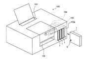
図10は上述した形態のインクタンク1を適用するプリンタの構成を示す模式図である。
“Usage example of
FIG. 10 is a schematic diagram showing a configuration of a printer to which the
プリンタは、インクジェット記録方式の記録ヘッドを着脱自在に搭載する不図示のキャリッジと、記録ヘッドから吐出されるインク滴によって画像が記録される記録シートを搬送する不図示の搬送手段とを備える。こうした構成に加えて、図10に示されるプリンタ100には、記録ヘッドによる画像記録領域に記録シートを送り込むためのシート搬入口101と、画像が記録された記録シートを排出するための排出口102とが設けられている。排出口102はプリンタの筐体正面に開口している。さらにプリンタ100には、記録ヘッドに供給するインクを収納した本発明のインクタンク1が着脱自在に装着されるインクタンク装着部としてのタンクホルダー103が装備され、タンクホルダー103へのインクタンクの装着口103aもプリンタの筐体正面に開口している。
The printer includes a carriage (not shown) on which an ink jet recording type recording head is detachably mounted, and a conveyance unit (not shown) that conveys a recording sheet on which an image is recorded by ink droplets ejected from the recording head. In addition to such a configuration, the
タンクホルダー103は、インクタンク1が図10に示した姿勢でプリンタ内に装着されることを可能する。よって、タンクホルダー103に装着されたインクタンク1は、インク供給口を開口したタンクケース6の側面やタンクケース6の最大面積の側面がプリンタ101の底面に対して略垂直である面と略平行に配される。さらにプリンタ100は机上などの略水平面に置かれるため、インク供給口を開口したタンクケース6の側面やタンクケース6の最大面積の側面は重力方向に略平行に配されることになる。
The
また、タンクホルダー103の装着口103aには、インクタンク1のインク供給口を形成するスパウト4および攪拌部材5の被操作部51が配置されている側の面を先頭にしてインクタンク1が装着される。
In addition, the
タンクホルダー103の奥には、記録ヘッド内の液室と接続チューブを介して接続されたインク供給手段としての針状のインク供給管(不図示)が設置されており、インクタンク1の装着完了で該インク供給管がインクタンク1のスパウト4のインク供給口を介してインク収納袋3内に進入し、インク収納袋3内のインクが記録ヘッドへ供給可能になる。
At the back of the
タンクホルダー103の奥には、さらに、インクタンク1の攪拌部材5を駆動するための駆動機構104が設置されている。この攪拌部材駆動機構104の例を図11,12に基づいて説明する。
A
図11は攪拌部材駆動機構104の構成を説明するための分解斜視図、図12は白斑部材駆動機構104の動作を説明するための模式図である。
FIG. 11 is an exploded perspective view for explaining the configuration of the stirring
図1,2等に示されているようにタンクケース6の、インク供給口を開口した側面にはへこみ64が設けられており、へこみ64内には攪拌部材5の被操作部51が突き出している。タンクホルダー103には、タンクホルダー103に装着されたインクタンク1のへこみ64に対応して切り欠き103bが形成されている。複数個のインクタンク1をプリンタに装着できるように複数のタンクホルダー103は図11に示すように並列に配設されており、全てのタンクホルダー103の切り欠き103bを通るように板状の駆動部材105が水平に配置されている。そして駆動部材105は、各タンクホルダー103の奥まで完全装着された各インクタンク1のへこみ64内の被操作部51に対して係合可能となっている。被操作部51は棒状であるため、駆動部材105にはそれと嵌合する溝105aが設けられている。
As shown in FIGS. 1 and 2, a
タンクホルダー103にインクタンク1が装着されると、インクタンク1における攪拌部材5の被操作部51が駆動部材105の溝105aに嵌合する。このため、駆動部材105をプリンタ設置面と略水平方向に往復駆動させることにより、被操作部51も同様に駆動してインク収納袋3内に攪拌部53でインク流れを発生させられる。
When the
板状の駆動部材105を往復運動させる装置は公知のどのような構成でもよいが、一例として、図11および図12に示した例のように回転運動を往復直線運動に変換できる装置が挙げられる。これらの図では、駆動部材105を固定した固定板106があり、固定板106の端に矩形の開口106aが設けられている。矩形の開口106aにおける短手方向の両長辺と円形カム107の周面が摺接しており、円形カム107は歯車108の中心の回転軸108aに偏心して取付けられている。歯車108はモータ109の回転軸と噛み合っている。このような構成によれば、図12の(a)〜(d)に示すように歯車108を時計回りにモータ109で回転させることで、固定板106と共に駆動部材105を略水平方向に往復駆動することができる。勿論、この構成は一例であり、これに本願発明は限定されない。
An apparatus for reciprocating the plate-
1 インクタンク
2 インク
3 インク収納袋
4 スパウト
5 攪拌部材
6 タンクケース
51 被操作部
52 攪拌部材溶着部
53 攪拌部
DESCRIPTION OF
Claims (11)
前記スパウトと前記被操作部とが共に前記タンクケースの一方の側に配置されており、前記スパウトが前記タンクケースと固定され、前記タンクケースの前記一方の側とは反対の他方の側に向かって前記インク収納袋が延在し、前記インク収納袋は前記タンクケースに固定されずに自由端を備えていることを特徴とするインクタンク。 A flexible ink storage bag, an ink supply spout and a stirring member respectively attached to the ink storage bag, and a tank case storing the ink storage bag. In an ink tank having an agitation unit that is disposed inside an ink storage bag and stirs ink, and an operation unit that is connected to the agitation unit and is located outside the ink storage bag and operates the agitation unit.
The spout and the operated part are both disposed on one side of the tank case, the spout is fixed to the tank case, and faces the other side opposite to the one side of the tank case. The ink storage bag extends, and the ink storage bag is not fixed to the tank case and has a free end.
記録シートに対してインク滴を吐出して画像を記録する記録ヘッドと、
前記インクタンクを着脱自在に装着するインクタンク装着部であって、装着された前記インクタンクの前記スパウトを介して前記記録ヘッドへインクを供給するインク供給手段と、前記攪拌部材の前記被操作部と係合して前記攪拌部材の前記攪拌部を駆動する攪拌部材駆動機構とを装備したインクタンク装着部と、
を備えたプリンタであって、
前記インクタンク装着部に装着された姿勢で前記インクタンク装着部の奥に位置する前記インクタンクの一方の側に前記スパウトと前記被操作部とが配置されており、前記スパウトが前記タンクケースと固定され、前記タンクケースの前記一方の側とは反対の他方の側に向かって前記インク収納袋が延在し、前記インク収納袋は前記タンクケースと固定されずに自由端を備えており、
前記インク供給手段および前記攪拌部材駆動機構は、前記タンクケースの前記一方の側に対応するように前記インクタンク装着部の奥に配置されていることを特徴とするプリンタ。 A flexible ink storage bag, an ink supply spout and a stirring member respectively attached to the ink storage bag, and a tank case storing the ink storage bag. An ink tank having an agitation unit disposed inside the ink storage bag and agitating the ink; and an operated unit connected to the agitation unit and positioned outside the ink storage bag to operate the agitation unit;
A recording head for recording an image by ejecting ink droplets onto the recording sheet;
An ink tank mounting portion for detachably mounting the ink tank, the ink supply means for supplying ink to the recording head via the spout of the mounted ink tank, and the operated portion of the stirring member An ink tank mounting portion equipped with a stirring member driving mechanism that engages with and drives the stirring portion of the stirring member;
A printer comprising:
The spout and the operated portion are arranged on one side of the ink tank located in the back of the ink tank mounting portion in a posture mounted on the ink tank mounting portion, and the spout is connected to the tank case. The ink storage bag extends toward the other side opposite to the one side of the tank case, and the ink storage bag has a free end without being fixed to the tank case;
The printer according to claim 1, wherein the ink supply unit and the stirring member driving mechanism are disposed at the back of the ink tank mounting portion so as to correspond to the one side of the tank case.
前記スパウトおよび前記攪拌部材は、前記タンクケースの前記一方の側に対応する前記インク収納袋の同じ辺縁に溶着されており、該攪拌部材の溶着部は該スパウトの溶着部から該辺縁に沿った方向にずれた位置にあり、
前記インク収納袋は顔料インクを収納しており、前記インクタンクが前記インクタンク装着部に装着された姿勢では、前記攪拌部材の溶着部が前記スパウトの溶着部より下方に位置することを特徴とする請求項4に記載のプリンタ。 The tank case is formed in a flat parallelepiped, and the ink storage bag is a rectangular bag made of a flexible film,
The spout and the stirring member are welded to the same edge of the ink storage bag corresponding to the one side of the tank case, and the welded portion of the stirring member extends from the welded portion of the spout to the edge. At a position shifted in the direction along
The ink storage bag stores pigment ink, and in a posture in which the ink tank is mounted on the ink tank mounting portion, the welding portion of the stirring member is positioned below the welding portion of the spout. The printer according to claim 4.
前記インク収納袋を収納した筐体と、A housing containing the ink storage bag;
前記インク収納袋に取り付けられたインク供給用スパウトと、An ink supply spout attached to the ink storage bag;
前記インク収納袋の内部に配されインクを撹拌する撹拌部と、前記撹拌部と接続され前記インク収納袋の外部に配され前記撹拌部を操作するための被操作部とを具備し、前記インク収納袋に取り付けられた撹拌部材と、An agitation unit disposed inside the ink storage bag for agitating ink; and an operated unit connected to the agitation unit and disposed outside the ink storage bag for operating the agitation unit. A stirring member attached to the storage bag;
を有するインクタンクにおいて、In an ink tank having
前記インク供給用スパウトと前記被操作部とが前記筺体の同じ面側に配されており、The ink supply spout and the operated portion are arranged on the same surface side of the casing,
前記撹拌部によるインクの撹拌に伴って前記インク収納袋が揺動可能であることを特徴とするインクタンク。An ink tank, wherein the ink storage bag can swing as ink is stirred by the stirring unit.
前記インク収納袋は、前記インク供給用スパウトを介して前記筺体に固定されていることを特徴とする請求項7に記載のインクタンク。The ink tank according to claim 7, wherein the ink storage bag is fixed to the casing via the ink supply spout.
Priority Applications (4)
| Application Number | Priority Date | Filing Date | Title |
|---|---|---|---|
| JP2010117252A JP5495942B2 (en) | 2010-05-21 | 2010-05-21 | Ink tank and printer |
| CN201110126787.2A CN102248802B (en) | 2010-05-21 | 2011-05-17 | Ink cartridge and printer |
| EP11166508.9A EP2388144B1 (en) | 2010-05-21 | 2011-05-18 | Ink cartridge and printer |
| US13/110,821 US8801160B2 (en) | 2010-05-21 | 2011-05-18 | Ink cartridge and printer |
Applications Claiming Priority (1)
| Application Number | Priority Date | Filing Date | Title |
|---|---|---|---|
| JP2010117252A JP5495942B2 (en) | 2010-05-21 | 2010-05-21 | Ink tank and printer |
Publications (3)
| Publication Number | Publication Date |
|---|---|
| JP2011240687A JP2011240687A (en) | 2011-12-01 |
| JP2011240687A5 JP2011240687A5 (en) | 2013-07-04 |
| JP5495942B2 true JP5495942B2 (en) | 2014-05-21 |
Family
ID=44352176
Family Applications (1)
| Application Number | Title | Priority Date | Filing Date |
|---|---|---|---|
| JP2010117252A Active JP5495942B2 (en) | 2010-05-21 | 2010-05-21 | Ink tank and printer |
Country Status (4)
| Country | Link |
|---|---|
| US (1) | US8801160B2 (en) |
| EP (1) | EP2388144B1 (en) |
| JP (1) | JP5495942B2 (en) |
| CN (1) | CN102248802B (en) |
Families Citing this family (5)
| Publication number | Priority date | Publication date | Assignee | Title |
|---|---|---|---|---|
| JP6081198B2 (en) * | 2009-09-24 | 2017-02-15 | コーニンクラケ ダウ エグバート ビー.ブイ. | Beverage cartridge |
| JP6210268B2 (en) | 2013-03-27 | 2017-10-11 | セイコーエプソン株式会社 | Printing device |
| JP6163890B2 (en) * | 2013-06-06 | 2017-07-19 | セイコーエプソン株式会社 | Liquid supply device, liquid container |
| RU2663383C2 (en) | 2014-01-03 | 2018-08-03 | Конинклейке Дауве Егбертс Б.В. | Method of operational commissioning replaceable feed unit in beverage dispenser and system containing replaceable feed unit and computer software product |
| JP6780321B2 (en) | 2016-06-28 | 2020-11-04 | セイコーエプソン株式会社 | Printing equipment and printing method |
Family Cites Families (19)
| Publication number | Priority date | Publication date | Assignee | Title |
|---|---|---|---|---|
| EP1122074B1 (en) | 2000-02-03 | 2006-04-12 | Canon Kabushiki Kaisha | Inks-and-printing-media-integrated pack, ink-jet printing apparatus and method |
| US7093710B2 (en) * | 2002-10-31 | 2006-08-22 | Brother Kogyo Kabushiki Kaisha | Ink-package assembly, and method of producing the same |
| JP2005067094A (en) * | 2003-08-26 | 2005-03-17 | Seiko Epson Corp | Liquid pack and liquid ejector |
| JP2005066520A (en) * | 2003-08-26 | 2005-03-17 | Seiko Epson Corp | Liquid housing body, liquid tank, liquid stirrer and liquid injector |
| JP4203385B2 (en) * | 2003-09-11 | 2008-12-24 | 東芝テック株式会社 | Inkjet ink |
| JP4478927B2 (en) * | 2004-03-10 | 2010-06-09 | セイコーエプソン株式会社 | Liquid container |
| JP2005254565A (en) | 2004-03-10 | 2005-09-22 | Seiko Epson Corp | Container for liquid |
| JP2006044153A (en) | 2004-08-06 | 2006-02-16 | Seiko Epson Corp | Liquid storing body and liquid injection device |
| US7556679B2 (en) * | 2005-08-04 | 2009-07-07 | Xerox Corporation | Processes for preparing phase change inks |
| EP1764223B1 (en) * | 2005-09-02 | 2009-01-14 | Canon Kabushiki Kaisha | Liquid container |
| JP4235633B2 (en) * | 2005-09-02 | 2009-03-11 | キヤノン株式会社 | Ink tank and recording device |
| US7621627B2 (en) * | 2005-09-02 | 2009-11-24 | Canon Kabushiki Kaisha | Liquid container |
| JP2007118295A (en) | 2005-10-26 | 2007-05-17 | Canon Inc | Liquid container |
| JP2007296644A (en) * | 2006-04-27 | 2007-11-15 | Canon Inc | Ink tank and inkjet recorder |
| JP4886586B2 (en) * | 2006-05-09 | 2012-02-29 | キヤノン株式会社 | Liquid storage container, head cartridge, inkjet recording apparatus, and liquid storage container stirring method |
| JP4926538B2 (en) * | 2006-05-11 | 2012-05-09 | キヤノン株式会社 | Liquid storage container and recording apparatus |
| JP2008273045A (en) * | 2007-04-27 | 2008-11-13 | Canon Inc | Liquid storage container, liquid stirring apparatus, and recording device |
| JP2009073091A (en) * | 2007-09-21 | 2009-04-09 | Canon Inc | Inkjet recorder and method for agitating ink |
| JP5159431B2 (en) * | 2008-05-23 | 2013-03-06 | 株式会社セイコーアイ・インフォテック | Ink cartridge and recording apparatus |
-
2010
- 2010-05-21 JP JP2010117252A patent/JP5495942B2/en active Active
-
2011
- 2011-05-17 CN CN201110126787.2A patent/CN102248802B/en active Active
- 2011-05-18 US US13/110,821 patent/US8801160B2/en active Active
- 2011-05-18 EP EP11166508.9A patent/EP2388144B1/en active Active
Also Published As
| Publication number | Publication date |
|---|---|
| EP2388144A1 (en) | 2011-11-23 |
| CN102248802B (en) | 2014-03-19 |
| CN102248802A (en) | 2011-11-23 |
| US8801160B2 (en) | 2014-08-12 |
| US20110285798A1 (en) | 2011-11-24 |
| JP2011240687A (en) | 2011-12-01 |
| EP2388144B1 (en) | 2013-10-16 |
Similar Documents
| Publication | Publication Date | Title |
|---|---|---|
| JP5854118B2 (en) | Fluid ejection device | |
| TWI337944B (en) | ||
| JP5495942B2 (en) | Ink tank and printer | |
| JP5761324B2 (en) | Recording apparatus and liquid ejecting apparatus | |
| JP4337894B2 (en) | Fluid container | |
| JP2012161989A (en) | Agitating device and liquid ejecting apparatus | |
| JP2008273173A (en) | Liquid container | |
| JP2007152733A (en) | Inkjet recording apparatus and ink tank therefor | |
| EP2481595B1 (en) | Liquid storage container mounted on liquid ejecting apparatus | |
| JP2009023233A (en) | Formation of flow passage of fluid | |
| JP2011240687A5 (en) | ||
| US9555641B2 (en) | Liquid supply system | |
| JP5617215B2 (en) | Liquid ejecting apparatus, liquid container | |
| JP5824945B2 (en) | Ink cartridge and inkjet printer | |
| JP2001219575A (en) | Ink-jet recording apparatus | |
| JP2001277535A (en) | Ink-jet recording apparatus | |
| JP2013176885A (en) | Liquid spraying device |
Legal Events
| Date | Code | Title | Description |
|---|---|---|---|
| A521 | Written amendment |
Free format text: JAPANESE INTERMEDIATE CODE: A523 Effective date: 20130520 |
|
| A621 | Written request for application examination |
Free format text: JAPANESE INTERMEDIATE CODE: A621 Effective date: 20130520 |
|
| A977 | Report on retrieval |
Free format text: JAPANESE INTERMEDIATE CODE: A971007 Effective date: 20140123 |
|
| TRDD | Decision of grant or rejection written | ||
| A01 | Written decision to grant a patent or to grant a registration (utility model) |
Free format text: JAPANESE INTERMEDIATE CODE: A01 Effective date: 20140204 |
|
| A61 | First payment of annual fees (during grant procedure) |
Free format text: JAPANESE INTERMEDIATE CODE: A61 Effective date: 20140304 |
|
| R151 | Written notification of patent or utility model registration |
Ref document number: 5495942 Country of ref document: JP Free format text: JAPANESE INTERMEDIATE CODE: R151 |