JP5495095B2 - Image forming apparatus - Google Patents
Image forming apparatus Download PDFInfo
- Publication number
- JP5495095B2 JP5495095B2 JP2009117204A JP2009117204A JP5495095B2 JP 5495095 B2 JP5495095 B2 JP 5495095B2 JP 2009117204 A JP2009117204 A JP 2009117204A JP 2009117204 A JP2009117204 A JP 2009117204A JP 5495095 B2 JP5495095 B2 JP 5495095B2
- Authority
- JP
- Japan
- Prior art keywords
- image
- image forming
- latent image
- sub
- forming apparatus
- Prior art date
- Legal status (The legal status is an assumption and is not a legal conclusion. Google has not performed a legal analysis and makes no representation as to the accuracy of the status listed.)
- Expired - Fee Related
Links
Images


Description
本発明は、複写機、プリンタ、ファクシミリ等の画像形成装置に係り、詳しくは、像担持体の表面上に形成された画像を転写領域で転写部材の表面移動により搬送される記録材上に転写する画像形成装置に関するものである。 The present invention relates to an image forming apparatus such as a copying machine, a printer, and a facsimile machine. More specifically, an image formed on the surface of an image carrier is transferred onto a recording material conveyed by the surface movement of a transfer member in a transfer region. The present invention relates to an image forming apparatus.
この種の画像形成装置においては、表面移動する像担持体と、その像担持体の表面と対向して表面移動する転写部材とを備え、その像担持体の表面上に形成された画像を、転写領域で、その像担持体と対向する転写部材の表面移動によって搬送されてくる記録材上に転写するものが知られている。具体的には、例えば、感光体等の潜像担持体(像担持体)上に形成した画像を記録紙等の記録材に直接転写して画像を形成する直接転写方式のものや、潜像担持体上に形成した画像をいったん中間転写体等の像担持体に転写し、その像担持体に転写した画像を最終的に記録材に転写して画像を形成する中間転写方式のものなどがある。 In this type of image forming apparatus, an image carrier that moves on the surface and a transfer member that moves on the surface facing the surface of the image carrier, and an image formed on the surface of the image carrier, In the transfer area, there is known a transfer region that is transferred onto a recording material conveyed by the surface movement of a transfer member facing the image carrier. Specifically, for example, a direct transfer type in which an image formed on a latent image carrier (image carrier) such as a photoconductor is directly transferred to a recording material such as recording paper to form an image, or a latent image There are intermediate transfer types that transfer the image formed on the carrier once to an image carrier such as an intermediate transfer member, and finally transfer the image transferred to the image carrier to a recording material to form an image. is there.
このような画像形成装置においては、種々の要因によって、本来の画像よりも記録材搬送方向(あるいは像担持体表面移動方向)に伸びた画像や縮んだ画像が形成されることがある。このような画像の伸び縮みを副走査倍率誤差と呼ぶ。
特許文献1には、画像形成手段の使用累積時間や画像形成回数に基づいて補正動作モードへ移行する中間転写方式の画像形成装置が開示されている。この補正動作モードでは、中間転写ベルト表面移動方向における画像の伸び縮み(副走査倍率誤差)を測定可能なパターン画像を中間転写ベルト上に形成し、これを中間転写ベルト上にてセンサで読み取る。そして、その副走査倍率誤差に基づいて中間転写ベルトの表面移動速度やレジストローラの回転速度の調整値を算出する。この調整値を用いて中間転写ベルトの表面移動速度やレジストローラの回転速度を制御することで、中間転写ベルト上で生じる画像の伸び縮みを抑制でき、その結果、記録材上における副走査倍率誤差が抑制される。
また、特許文献2には、回転感光体の表面に対して感光体表面移動方向に複数の潜像構成部を順次形成することにより当該複数の潜像構成部からなる一の潜像(一ページ分の潜像)を形成する中間転写方式の画像形成装置が開示されている。この画像形成装置は、単一の回転感光体上に複数色の画像を順次形成し、各画像が中間転写ベルト上で互いに重なり合うように転写することでカラー画像を形成する。この画像形成装置では、ある色の作像時の中間転写ベルト回転負荷が他色の作像時の中間転写ベルト回転負荷と異なる場合に、各色の潜像形成時における複数の潜像構成部の感光体表面移動方向における間隔(書き込み倍率)をその回転負荷の差に応じて変更する。この画像形成装置によれば、中間転写ベルトクリーナが中間転写ベルトに当接している状態の負荷と当接していない状態の負荷との差に起因した中間転写ベルト上で生じる画像の伸び縮みを抑制でき、その結果、記録材上における副走査倍率誤差が抑制される。
In such an image forming apparatus, an image that extends in the recording material conveyance direction (or the image carrier surface movement direction) or a contracted image than the original image may be formed due to various factors. Such expansion / contraction of the image is called a sub-scanning magnification error.
Patent Document 1 discloses an intermediate transfer type image forming apparatus that shifts to a correction operation mode based on the accumulated use time of the image forming means and the number of image formations. In this correction operation mode, a pattern image capable of measuring image expansion / contraction (sub-scanning magnification error) in the intermediate transfer belt surface movement direction is formed on the intermediate transfer belt, and this is read by the sensor on the intermediate transfer belt. Based on the sub-scanning magnification error, an adjustment value for the surface movement speed of the intermediate transfer belt and the rotation speed of the registration roller is calculated. By using this adjustment value to control the surface transfer speed of the intermediate transfer belt and the rotation speed of the registration roller, it is possible to suppress the expansion and contraction of the image that occurs on the intermediate transfer belt. Is suppressed.
Further,
ところが、本発明者の研究の結果、上述した特許文献1や特許文献2に記載の画像形成装置では抑制できない副走査倍率誤差が生じることが判明した。
具体的に説明すると、上述した特許文献1や特許文献2に記載の画像形成装置は、いずれも、中間転写ベルト(像担持体)上に画像が形成されるまでの要因(中間転写ベルトの表面移動速度変動や潜像担持体の表面移動速度変動など)に起因した画像の伸び縮みを抑制することは可能である。しかし、中間転写ベルト(像担持体)上に画像が形成されてからその画像が記録材上に転写されるまでの間に生じる要因に起因した画像の伸び縮みは、抑制することができない。そして、本発明者は、像担持体から記録材へ画像を転写する転写領域における、像担持体の表面上に担持されている画像の移動速度と記録材の搬送速度との速度差が、この要因となることを突き止めた。
However, as a result of the inventor's research, it has been found that a sub-scanning magnification error that cannot be suppressed by the image forming apparatuses described in Patent Document 1 and
Specifically, in the image forming apparatuses described in Patent Document 1 and
すなわち、通常の画像形成装置では、画像の移動速度と記録材の搬送速度との速度差が無い状態で画像形成を行う。ところが、何らかの原因で、上記転写領域において画像の移動速度の方が記録材の搬送速度よりも速くなると、正常状態のときの画像よりも画像全体が記録材搬送方向(あるいは像担持体表面移動方向)に伸びた画像が形成される。また、逆に、何らかの原因で、上記転写領域において記録材の搬送速度の方が画像の移動速度よりも速くなると、正常状態のときの画像よりも画像全体が記録材搬送方向に縮んだ画像が形成される。この原因としては、次のようなものが考えられる。像担持体から記録材へ画像を転写する転写領域において、その像担持体と対向する転写部材の表面移動速度が変動すると、その転写部材の表面移動によって搬送される記録材の搬送速度も変動する。そのため、転写部材の表面移動速度が変動すると、転写領域における像担持体表面上の画像の移動速度と記録材の搬送速度との間に速度差が生じる。したがって、転写部材の表面移動速度変動は、上記原因となり得る。 That is, in an ordinary image forming apparatus, image formation is performed in a state where there is no speed difference between the moving speed of the image and the conveying speed of the recording material. However, if for some reason the moving speed of the image in the transfer area becomes faster than the transport speed of the recording material, the entire image is moved in the recording material transport direction (or the image carrier surface moving direction) than in the normal state. ) Is formed. Conversely, if for some reason the recording material transport speed in the transfer area is faster than the image movement speed, the image is contracted in the recording material transport direction more than the normal image. It is formed. The following can be considered as this cause. In the transfer area where the image is transferred from the image carrier to the recording material, if the surface movement speed of the transfer member facing the image carrier fluctuates, the conveyance speed of the recording material conveyed by the surface movement of the transfer member also fluctuates. . Therefore, when the surface moving speed of the transfer member varies, a speed difference is generated between the moving speed of the image on the surface of the image carrier in the transfer region and the conveying speed of the recording material. Therefore, the fluctuation in the surface moving speed of the transfer member can cause the above.
転写部材の表面移動速度を変動させる要因としては、例えば、転写部材が転写ローラである場合にはそのローラ経の変動、転写部材が転写ベルトである場合にはその転写ベルトを張架するローラのローラ経の変動が挙げられる。このようなローラ経の変動は、温度・湿度等の環境変動により生じ得る。具体的には、転写部材が転写ローラである場合を例に挙げて説明すると、環境変動により転写ローラが膨張し、そのローラ経が大きくなると、転写ローラの表面移動速度が増加し、これにより記録材の搬送速度も増加する。逆に、環境変動により転写ローラが収縮し、そのローラ経が小さくなると、転写ローラの表面移動速度が減少し、これにより記録材の搬送速度も減少する。 Factors that cause the surface movement speed of the transfer member to fluctuate include, for example, when the transfer member is a transfer roller, fluctuations in the roller length, and when the transfer member is a transfer belt, the roller that stretches the transfer belt The variation of roller warp is mentioned. Such fluctuations in the roller diameter can be caused by environmental fluctuations such as temperature and humidity. Specifically, the case where the transfer member is a transfer roller will be described as an example. When the transfer roller expands due to environmental fluctuations and the roller diameter increases, the surface movement speed of the transfer roller increases, thereby recording. The material transport speed also increases. Conversely, when the transfer roller contracts due to environmental fluctuations and the roller diameter becomes smaller, the surface movement speed of the transfer roller decreases, thereby reducing the conveyance speed of the recording material.
なお、上記特許文献1に記載の画像形成装置では、中間転写ベルト(像担持体)の表面移動速度だけでなくレジストローラの回転速度も補正しているが、転写領域中における記録紙の搬送速度は、レジストローラの回転速度よりも転写部材の表面移動速度の方が支配的である。そのため、転写部材の表面移動速度が変動すると、レジストローラの回転速度を補正しても、記録紙の搬送速度は変動し、転写領域における中間転写ベルトの表面上に担持されている画像の移動速度と記録紙の搬送速度との速度差を小さくすることはできない。したがって、上記特許文献1に記載の画像形成装置でも、転写部材の表面移動速度が変動することに起因した副走査倍率誤差を抑制することはできない。 In the image forming apparatus described in Patent Document 1, not only the surface movement speed of the intermediate transfer belt (image carrier) but also the rotation speed of the registration roller is corrected, but the recording paper conveyance speed in the transfer area is corrected. The surface movement speed of the transfer member is more dominant than the rotation speed of the registration roller. Therefore, if the surface movement speed of the transfer member varies, even if the rotation speed of the registration roller is corrected, the conveyance speed of the recording paper varies, and the movement speed of the image carried on the surface of the intermediate transfer belt in the transfer area And the speed difference between the recording paper transport speed cannot be reduced. Therefore, even the image forming apparatus described in Patent Document 1 cannot suppress the sub-scanning magnification error caused by the change in the surface moving speed of the transfer member.
本発明は、上記問題点に鑑みなされたものであり、その目的は、転写部材の表面移動速度が変動することに起因して画像全体が伸びたり縮んだりする副走査倍率誤差を抑制することが可能な画像形成装置を提供することである。 The present invention has been made in view of the above problems, and an object thereof is to suppress a sub-scanning magnification error in which the entire image expands or contracts due to fluctuations in the surface movement speed of the transfer member. It is an object to provide a possible image forming apparatus.
上記目的を達成するために、請求項1の発明は、表面移動する像担持体と、該像担持体の表面と対向して表面移動する転写部材と、該転写部材を表面移動させるための駆動力を該転写部材へ付与する駆動力付与手段とを備え、該像担持体の表面上に形成された画像を、該像担持体の表面と該転写部材の表面とが互いに対向する転写領域で、該転写部材の表面移動により搬送される記録材上に転写する画像形成装置において、連続画像形成動作中における2つの画像間の非画像領域に対応した所定のタイミングで、上記像担持体の表面上に、画像の記録材搬送方向における伸び縮み量を測定するためのパターン画像を形成して、該像担持体及び上記転写部材を画像形成工程時と同じ表面移動速度で駆動した状態で、該パターン画像を上記転写部材の表面に転写することにより、該転写部材の表面上にパターン画像を作成するパターン画像作成手段と、該パターン画像作成手段により作成された該転写部材の表面上のパターン画像を検知する検知手段と、該検知手段の検知結果から算出される上記パターン画像の記録材搬送方向長さと、該パターン画像の記録材搬送方向における伸び縮みが無いと仮定した環境での理想の記録材搬送方向長さとの誤差を算出し、算出した誤差が予め規定された補正可能範囲内であれば、算出した誤差に基づいて次回以降の画像形成工程で形成される画像の記録材搬送方向における伸び縮み量が少なくなるように画像形成条件の補正処理を行い、算出した誤差が該補正可能範囲外であれば該補正処理を行わない補正処理手段とを有し、上記補正処理手段が行う上記補正処理は、上記転写部材の表面移動速度を変更する処理を含むことを特徴とするものである。
また、請求項2の発明は、請求項1の画像形成装置において、互いに色が異なる複数の単色画像を互いに重ね合わせて上記像担持体の表面上にカラー画像を形成するものであって、上記パターン画像作成手段は、いずれか1つの単色画像からなるパターン画像を上記転写部材の表面上に作成することを特徴とするものである。
また、請求項3の発明は、請求項1又は2の画像形成装置において、表面移動する潜像担持体と、表面移動する潜像担持体の表面に潜像を形成する潜像形成手段と、該潜像形成手段により形成した潜像をトナーにより現像する現像手段と、該現像手段による現像によって得られた画像を上記像担持体の表面に転写する転写手段とを有することを特徴とするものである。
また、請求項4の発明は、請求項3の画像形成装置において、上記潜像形成手段は、表面移動する潜像担持体の表面に対し、該潜像担持体の表面移動方向に複数の潜像構成部を順次形成することにより、該複数の潜像構成部からなる一の潜像を形成するものであり、上記補正処理手段が行う上記補正処理は、上記潜像形成手段により形成される上記複数の潜像構成部の潜像担持体表面移動方向における間隔を変更する処理を含むことを特徴とするものである。
また、請求項5の発明は、請求項1の画像形成装置において、表面移動する上記像担持体の表面に対し、該像担持体の表面移動方向に複数の潜像構成部を順次形成することにより、該複数の潜像構成部からなる一の潜像を形成する潜像形成手段と、該潜像形成手段により形成した潜像をトナーにより現像する現像手段と、該現像手段による現像によって得られた画像を上記記録材上に転写する転写手段とを有し、上記補正処理手段が行う上記補正処理は、上記潜像形成手段により形成される上記複数の潜像構成部の像担持体表面移動方向における間隔を変更する処理を含むことを特徴とするものである。
また、請求項6の発明は、請求項1乃至5のいずれか1項に記載の画像形成装置において、上記補正処理手段は、上記補正処理を行う前に、上記検知手段の検知結果に基づいて画像の記録材搬送方向における伸び縮み量が補正可能範囲内であるか否かを判断し、補正範囲内であると判断した場合には該補正処理を行い、補正範囲外であると判断した場合には該補正処理を行わないことを特徴とするものである。
また、請求項7の発明は、請求項1乃至6のいずれか1項に記載の画像形成装置において、装置内の温度を検知する温度検知手段を有し、上記所定のタイミングは、該温度検知手段の検知結果に基づき、連続画像形成中の初期時からの温度変化量が規定量を超えた時のタイミングであることを特徴とするものである。
In order to achieve the above object, the invention of claim 1 is directed to an image carrier that moves on the surface, a transfer member that moves opposite to the surface of the image carrier, and a drive for moving the surface of the transfer member. Driving force applying means for applying a force to the transfer member, and an image formed on the surface of the image carrier is transferred to a transfer region where the surface of the image carrier and the surface of the transfer member face each other. In the image forming apparatus for transferring onto the recording material conveyed by the surface movement of the transfer member, the surface of the image carrier at a predetermined timing corresponding to the non-image area between the two images during the continuous image forming operation. A pattern image for measuring the amount of expansion and contraction of the image in the recording material conveyance direction is formed, and the image carrier and the transfer member are driven at the same surface moving speed as in the image forming step. Transfer the pattern image to the transfer section A pattern image creating means for creating a pattern image on the surface of the transfer member by transferring to the surface of the transfer member; and a detecting means for detecting the pattern image on the surface of the transfer member created by the pattern image creating means; , The length of the pattern image in the recording material conveyance direction calculated from the detection result of the detection means, and the ideal length of the recording material conveyance direction in an environment assuming that there is no expansion / contraction in the recording material conveyance direction of the pattern image. calculates an error, if the calculated correction range of error is defined in advance, the amount of expansion and contraction in the recording material conveyance direction of the image is small, which is formed by the image forming process in the subsequent times based on the calculated error There line correction processing of the image forming conditions so that, if the calculated error at the correctable range and a correcting means not to perform the correction processing, is the correction processing means Cormorant the correction process are those characterized by comprising a process for changing the surface moving speed of the transfer member.
According to a second aspect of the present invention, in the image forming apparatus of the first aspect, a plurality of single-color images having different colors are superimposed on each other to form a color image on the surface of the image carrier. The pattern image creating means creates a pattern image composed of any one single color image on the surface of the transfer member.
The invention according to claim 3 is the image forming apparatus according to
According to a fourth aspect of the present invention, in the image forming apparatus according to the third aspect, the latent image forming means includes a plurality of latent images in the surface moving direction of the latent image carrier with respect to the surface of the latent image carrier. By sequentially forming the image constituent parts, one latent image composed of the plurality of latent image constituent parts is formed, and the correction processing performed by the correction processing means is formed by the latent image forming means. The method includes a process of changing the interval in the moving direction of the surface of the latent image carrier of the plurality of latent image forming units.
According to a fifth aspect of the present invention, in the image forming apparatus of the first aspect, a plurality of latent image constituting portions are sequentially formed in the surface moving direction of the image carrier on the surface of the image carrier that moves on the surface. The latent image forming means for forming one latent image composed of the plurality of latent image forming portions, the developing means for developing the latent image formed by the latent image forming means with toner, and the development by the developing means. Transfer means for transferring the image formed on the recording material, and the correction processing performed by the correction processing means is performed on the surface of the image carrier of the plurality of latent image forming portions formed by the latent image forming means. It includes a process of changing the interval in the moving direction.
According to a sixth aspect of the present invention, in the image forming apparatus according to any one of the first to fifth aspects, the correction processing means is based on a detection result of the detection means before performing the correction processing. When it is determined whether the amount of expansion / contraction in the recording material conveyance direction of the image is within the correctable range, and when it is determined that it is within the correction range, the correction processing is performed, and when it is determined that it is outside the correction range Is characterized in that the correction processing is not performed.
According to a seventh aspect of the present invention, in the image forming apparatus according to any one of the first to sixth aspects of the present invention, the image forming apparatus further includes a temperature detection unit that detects a temperature in the apparatus, and the predetermined timing is determined by the temperature detection. Based on the detection result of the means, it is a timing when the temperature change amount from the initial time during the continuous image formation exceeds a specified amount.
本発明において、画像の記録材搬送方向における伸び縮み量を少なくする画像形成条件の補正処理は、像担持体の表面上から転写部材の表面に転写して得られるパターン画像の検知結果に基づいて行われる。このパターン画像の検知結果には、転写領域における像担持体表面上に担持されている画像の移動速度と記録材の搬送速度との速度差に応じた画像の伸び縮みが反映される。したがって、このパターン画像の検知結果には、転写部材の表面移動速度が変動することに起因した画像全体の伸び縮み(副走査倍率誤差)も反映されている。よって、このパターン画像の検知結果に基づいて補正処理を行うことにより、転写部材の表面移動速度が変動することに起因して画像全体が伸びたり縮んだりする副走査倍率誤差を抑制することができる。 In the present invention, the image forming condition correction processing for reducing the amount of expansion / contraction in the recording material conveyance direction of the image is based on the detection result of the pattern image obtained by transferring from the surface of the image carrier to the surface of the transfer member. Done. The detection result of the pattern image reflects the expansion and contraction of the image according to the speed difference between the moving speed of the image carried on the surface of the image carrier in the transfer region and the conveyance speed of the recording material. Therefore, the detection result of the pattern image also reflects the expansion / contraction of the entire image (sub-scanning magnification error) caused by the change in the surface moving speed of the transfer member. Therefore, by performing the correction process based on the detection result of the pattern image, it is possible to suppress a sub-scanning magnification error that causes the entire image to expand or contract due to fluctuations in the surface moving speed of the transfer member. .
以上、本発明によれば、転写部材の表面移動速度が変動することに起因して画像全体が伸びたり縮んだりする副走査倍率誤差を抑制することが可能となるという優れた効果が得られる。 As described above, according to the present invention, it is possible to obtain an excellent effect that it is possible to suppress a sub-scanning magnification error in which the entire image is stretched or contracted due to fluctuations in the surface moving speed of the transfer member.
以下、本発明を、画像形成装置としてのプリンタに適用した一実施形態について説明する。
なお、本実施形態に係るプリンタは、像担持体としての中間転写体である中間転写ベルトの表面移動方向に沿って潜像担持体である4つの感光体が配置された、いわゆるタンデム型のカラー画像形成装置であるが、本発明はこのような画像形成装置に限られない。
Hereinafter, an embodiment in which the present invention is applied to a printer as an image forming apparatus will be described.
Note that the printer according to the present embodiment is a so-called tandem color printer in which four photoconductors that are latent image carriers are arranged along the surface movement direction of an intermediate transfer belt that is an intermediate transfer member as an image carrier. Although it is an image forming apparatus, the present invention is not limited to such an image forming apparatus.
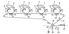
図1は、本実施形態に係るプリンタの主要部を示す概略構成図である。
このプリンタは、4つの感光体5,6,7,8の表面上にそれぞれ形成される4色の単色画像(単色トナー像)を中間転写ベルト21の表面上で互いに重ね合わせることで1ページの画像を形成するものである。4つの感光体5,6,7,8の表面上には、潜像形成手段としての光書込ユニット1,2,3,4によりそれぞれ静電潜像が形成される。形成された静電潜像は、図中矢印Bの方向に回転駆動する感光体の回転に伴って現像手段としての現像装置9,10,11,12と対向する現像領域へ搬送される。各感光体5,6,7,8上の静電潜像には、それぞれの現像装置9,10,11,12により各色のトナーが供給され、各静電潜像はトナー像化される。
FIG. 1 is a schematic configuration diagram illustrating a main part of the printer according to the present embodiment.
In this printer, four-color single-color images (single-color toner images) respectively formed on the surfaces of the four photoconductors 5, 6, 7, and 8 are superposed on each other on the surface of the
4つの感光体5,6,7,8は、複数の支持ローラに張架されている中間転写ベルト21のベルト平坦部に接触した状態で、その表面移動方向(図中矢印Aの方向)に沿って並んで配置されている。各感光体と接触する部分の中間転写ベルト裏面側には、一次転写ローラ13,14,15,16が対向しており、各一次転写ローラ13,14,15,16には各感光体5,6,7,8上のトナー像を中間転写ベルト21の表面上に一次転写するための一次転写高圧電源17,18,19,20が接続されている。各感光体5,6,7,8の表面上に形成された各色トナー像は、各一次転写ローラ13,14,15,16により中間転写ベルト21の表面上で互いに重なり合うように、中間転写ベルト21の表面上に一次転写される。
The four photoconductors 5, 6, 7 and 8 are in contact with the belt flat portion of the
中間転写ベルト21の表面上に一次転写されたトナー像は、中間転写ベルト21の表面移動に伴って二次転写領域へと搬送される。二次転写領域には、中間転写ベルト21の裏面側に支持ローラである二次転写対向ローラ22が設けられ、中間転写ベルト21の表面側には転写部材としての二次転写ローラ23が設けられている。二次転写ローラ23は、駆動力付与手段としての駆動モータMにより回転駆動する。また、二次転写ローラ23は、中間転写ベルト21の表面に対して接離可能に構成されている。画像形成工程時には、図1に示すように、中間転写ベルト21と二次転写ローラ23とが当接状態となり、図中矢印Cで示すように二次転写領域へと搬送されてくる記録材としての用紙25は、中間転写ベルト21と二次転写ローラ23とに挟まれた状態で二次転写領域を通過する。この際、中間転写ベルト21の表面上に形成されているトナー像は、二次転写高圧電源24により二次転写バイアスが印加された二次転写ローラ23により、その二次転写ローラ23の表面移動により搬送される用紙25上に二次転写される。用紙25上に転写されたトナー像は、図示しない定着装置において用紙上に定着され、機外に排出される。
The toner image primarily transferred onto the surface of the
本実施形態においては、各感光体5,6,7,8の偏心等に起因して、それぞれの潜像書込位置での感光体表面移動速度が変動することにより、副走査倍率誤差が生じ得る。また、各感光体5,6,7,8の表面移動速度変動や中間転写ベルト21の表面移動速度変動などに起因して、各感光体5,6,7,8から中間転写ベルト21への各一次転写領域において感光体表面移動速度と中間転写ベルト表面移動速度との間に速度差が生じる場合も、副走査倍率誤差が生じ得る。本実施形態では、各感光体5,6,7,8の表面移動速度及び中間転写ベルト21の表面移動速度は、公知の方法により一定速度となるように制御されている。したがって、本実施形態では、中間転写ベルト21上の画像には、許容範囲を超えるような画像の伸び縮み(副走査倍率誤差)は生じない。
In the present embodiment, due to the eccentricity of each of the photoconductors 5, 6, 7, and 8, the surface movement speed of the photoconductor at each latent image writing position varies, thereby generating a sub-scanning magnification error. obtain. Further, due to fluctuations in the surface movement speed of the respective photoconductors 5, 6, 7, 8, fluctuations in the surface movement speed of the
しかしながら、二次転写領域における中間転写ベルト21の表面上に担持されているトナー像(画像)の移動速度と用紙25の搬送速度との速度差が生じると、用紙25上の画像には許容範囲を超えるような副走査倍率誤差が生じ得る。そこで、本実施形態では、後述するように、副走査倍率誤差を測定するためのパターン画像(以下「副走査倍率誤差測定用パターン」という。)を中間転写ベルト21上に形成し、これを二次転写ローラ23の表面上に転写したときの副走査倍率誤差測定用パターンを検知する検知手段としてのパターン検知センサ26を、二次転写領域とは反対側の二次転写ローラ23の表面部分に対向配置している。そして、二次転写領域における中間転写ベルト21の表面上の画像移動速度と用紙搬送速度との速度差に起因した副走査倍率誤差を抑制するために、パターン検知センサ26の検知結果を用いて次のような補正動作を所定のタイミングで行う。
However, if a speed difference between the moving speed of the toner image (image) carried on the surface of the
図2は、本実施形態における副走査倍率誤差の補正動作の流れを示すフローチャートである。
上記のような副走査倍率誤差は、既に説明したように、機内温度が上昇して、これに伴い二次転写ローラ23が膨張してそのローラ経が大きくなることにより生じる。すなわち、温度上昇に伴って二次転写ローラ23のローラ経が大きくなると、二次転写ローラ23の表面移動速度が増加し、これにより用紙25の搬送速度も増加するため、中間転写ベルト21上のトナー像の移動速度に対して用紙25の搬送速度が相対的に速くなり、用紙搬送方向に縮んだ画像が形成されてしまう。そこで、装置内の温度を検知する温度検知手段としての温度センサを設け、その温度センサが検知した温度が規定値以上の温度範囲にあるタイミングで、補正動作を行うようにしてもよい。ただし、本実施形態では、機内温度が大きく上昇するのは画像形成を連続して行っている時であることに鑑み、連続画像形成中の初期時からの温度変化量が規定量を超えた時のタイミングで、補正動作を行うこととしている。
FIG. 2 is a flowchart showing the flow of the sub-scanning magnification error correction operation in this embodiment.
As described above, the sub-scanning magnification error as described above is caused by an increase in the temperature inside the apparatus, and the
本実施形態における補正動作では、まず、通常の画像形成工程で画像形成に使用する構成を利用して、トナーによる副走査倍率測定用パターンを所定のプロセスにて中間転写ベルト21の表面上に作成する(S101)。そして、二次転写高圧電源24により二次転写バイアスを二次転写ローラ23に印加して、中間転写ベルト21の表面上に形成した副走査倍率測定用パターンを二次転写ローラ23の表面上に転写し(S102)、二次転写ローラ23の表面上の副走査倍率測定用パターンをパターン検知センサ26により検知する(S103)。その後、パターン検知センサ26の検知結果から、副走査倍率測定用パターンの二次転写ローラ表面移動方向長さ(副走査長)を算出(S104)し、この副走査長と、副走査倍率誤差が無いと仮定した環境での理想の副走査長とを比較して、現在の副走査倍率誤差を算出する(S105)。ここで、このようにして算出した副走査倍率誤差が、予め規定された補正可能範囲外であれば(S106のNo)、補正処理を行わずに補正動作を終了する。一方、算出した副走査倍率誤差が、予め規定された補正可能範囲内であれば(S106のYes)、後述する補正処理を行う(S107)。
In the correction operation in the present embodiment, first, a sub-scanning magnification measurement pattern using toner is created on the surface of the
以下、各ステップにおいて実行する処理・制御の詳細について説明する。
図3(a)及び(b)は、上記S101において作成する副走査倍率測定用パターンの一例を示す説明図である。
上記S101では、図3(a)に示すように、二次転写ローラ23の半径をRとし、二次転写ローラ軸方向(主走査方向)の有効書き込み範囲(画像形成可能範囲)をDとした場合、主走査方向長さがD[mm]で、副走査方向長さがL0=πR[mm](すなわち、二次転写ローラ23の半周分)である図3(b)に示すような副走査倍率測定用パターン27を作成する。この副走査倍率測定用パターン27は、任意の1色のトナーで作成すればよい。この副走査倍率測定用パターン27は、連続画像形成中における2つの画像間の領域に対応する中間転写ベルト21の表面部分に形成するのが好ましい。この場合、副走査倍率測定用パターン27を形成するために連続画像形成を中断せずに済む。
Details of processing and control executed in each step will be described below.
FIGS. 3A and 3B are explanatory diagrams showing an example of a sub-scanning magnification measurement pattern created in S101.
In S101, as shown in FIG. 3A, the radius of the
上記S101及び上記S102を実行するときの中間転写ベルト21及び二次転写ローラ23の表面移動速度は、通常の画像形成工程の時と同じ速度であっても、副走査倍率誤差補正用に個別に設定した速度であってもよい。後者の場合、中間転写ベルト21及び二次転写ローラ23の表面移動速度を変更する速度変更手段を設け、補正動作を行う際には、中間転写ベルト21及び二次転写ローラ23を画像形成工程時とは異なる表面移動速度で駆動した状態で、二次転写ローラ23の表面上に副走査倍率測定用パターンを作成する。
Even when the surface movement speeds of the
図4は、上記S103で用いるパターン検知センサ26の一例を示す説明図である。
上記S103で用いるパターン検知センサ26は、二次転写ローラ23の表面上でトナー像の有無を検知可能な光学センサ等を用いることができる。このようなセンサを用いる場合、パターン検知センサ26の出力信号と、二次転写ローラ23の表面上に転写された副走査倍率測定用パターン27との関係は、図4に示すようになる。このとき、副走査倍率測定用パターン27は、二次転写ローラ23の表面移動に伴ってパターン検知センサ26の検知領域を通過することになるので、二次転写ローラ23の表面移動速度Vと同じ速度で移動する。パターン検知センサ26の検知領域に副走査倍率測定用パターン27の先端が到達すると、パターン検知センサ26の出力信号がON状態となり、副走査倍率測定用パターン27の後端が抜けると、パターン検知センサ26の出力信号はOFF状態となる。したがって、パターン検知センサ26の出力信号がON状態になった時刻をT0とし、パターン検知センサ26の出力信号がOFF状態になった時刻をT1とすると、二次転写ローラ23上に転写された副走査倍率測定用パターン27の副走査長(測定副走査長)L1は、次の式(1)で表される。
L1 = (T1−T0)×V ・・・(1)
FIG. 4 is an explanatory diagram showing an example of the
As the
L1 = (T1-T0) × V (1)
ここで、パターン検知センサ26にて検知される副走査倍率測定用パターン27の測定副走査長L1は、中間転写ベルト21の表面上から二次転写ローラ23の表面上へ転写されたトナー像の副走査長である。そのため、二次転写領域において中間転写ベルト21と二次転写ローラ23との間で表面移動速度差が生じていると、二次転写ローラ23へ転写されることで、二次転写前の副走査長(中間転写ベルト21の表面上における副走査倍率測定用パターン27の副走査長)と誤差が生じる。上述したとおり、二次転写ローラ23は温度・湿度などの環境によりローラ径が膨張・収縮することがある。二次転写ローラ23の表面移動速度Vは、二次転写ローラ23の回転角速度をωとしたとき、下記の式(2)のように表される。したがって、二次転写ローラ23の表面移動速度Vは、二次転写ローラ23のローラ径に依存して増減することになる。よって、ローラ径の変動は二次転写領域での中間転写ベルト21と二次転写ローラ23との表面移動速度差の原因となる。
V = ω×R ・・・(2)
Here, the measurement sub-scanning length L1 of the sub-scanning
V = ω × R (2)
上記S105において行われる副走査倍率誤差Cの算出は、副走査倍率誤差が無いと仮定した理想環境での副走査倍率測定用パターンの副走査長(理想副走査長)すなわち図3に示したL0と、上記S104において算出した副走査倍率誤差測定用パターンの測定副走査長すなわち図4に示したL1とから、下記の式(3)を用いて算出する。
C = {(L1/L0)×100}−100% ・・・(3)
The sub-scanning magnification error C calculated in S105 is calculated by sub-scanning length (ideal sub-scanning length) of the sub-scanning magnification measurement pattern in an ideal environment assuming that there is no sub-scanning magnification error, that is, L0 shown in FIG. And the measurement sub-scanning length of the sub-scanning magnification error measurement pattern calculated in S104, that is, L1 shown in FIG. 4, is calculated using the following equation (3).
C = {(L1 / L0) × 100} −100% (3)
上記S106では、上記S105にて算出した副走査倍率誤差Cが補正範囲内の値であるかどうかを判定する。ここで、副走査倍率誤差の補正範囲を決める一例としては、二次転写ローラ23を駆動するモータの速度可変範囲を考慮して決めてもよい。
In S106, it is determined whether or not the sub-scanning magnification error C calculated in S105 is a value within the correction range. Here, as an example of determining the correction range of the sub-scanning magnification error, it may be determined in consideration of the speed variable range of the motor that drives the
上記S107において行う副走査倍率誤差の補正処理としては、例えば、副走査倍率を変動させる要因となっている二次転写ローラ23の表面移動速度を直接補正する方法と、変動した副走査倍率に合わせて形成するトナー像を伸縮させるように光書込ユニット1,2,3,4の書き込み周波数を補正する方法とが挙げられる。
As the correction process of the sub-scanning magnification error performed in S107, for example, a method of directly correcting the surface moving speed of the
まず、前者の補正方法を用いた補正処理について説明する。
図5は、この補正処理の内容を説明するための説明図である。
なお、ここでの説明では、測定副走査長L1が理想副走査長L0よりも長くなっていて、+C[%]の副走査倍率誤差が生じている例について説明する。つまり、二次転写ローラ23のローラ径が膨張して、中間転写ベルト21の表面移動速度よりも二次転写ローラ23の表面移動速度の方が速くなっている例について説明する。この例において、+C[%]の副走査倍率誤差分だけ二次転写ローラ23の表面移動速度が減速するように、二次転写ローラ23の表面移動速度を補正する。具体的には、補正後の二次転写ローラ23の表面移動速度が下記の式(4)から算出されるVR1となるように補正する。なお、下記の式(4)中のVR0は、補正前の二次転写ローラ23の表面移動速度である。
VR1 = VR0+{VR0×(−C)} ・・・(4)
補正後の表面移動速度VR1で二次転写ローラ23を駆動する結果、二次転写ローラ23の表面移動速度と中間転写ベルト21の表面移動速度との速度差がなくなり、副走査倍率誤差Cを解消することが可能となる。
First, the correction process using the former correction method will be described.
FIG. 5 is an explanatory diagram for explaining the contents of the correction processing.
In the description here, an example in which the measured sub-scanning length L1 is longer than the ideal sub-scanning length L0 and a sub-scanning magnification error of + C [%] has occurred will be described. That is, an example in which the roller diameter of the
VR1 = VR0 + {VR0 × (−C)} (4)
As a result of driving the
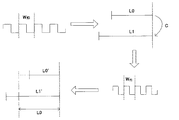
次に、後者の補正方法を用いた補正処理について説明する。
図6は、この補正処理の内容を説明するための説明図である。
なお、ここでの説明では、測定副走査長L1が理想副走査長L0よりも長くなっていて、書き込み周波数Wf0[Hz]で形成した副走査倍率誤差パターンから算出した副走査倍率誤差が+C[%]である例について説明する。この例においては、書き込み周波数Wf0[Hz]で中間転写ベルト21の表面上に形成したトナー像の副走査ライン間隔と、二次転写後の副走査ライン間隔とを比較すると、二次転写後の副走査ライン間隔の方が広くなる。つまり、狙いの副走査倍率を満たすには、書き込み周波数Wf0[Hz]での副走査ライン間隔の形成では書き込み周波数が低いということになる。したがって、二次転写後の副走査ライン間隔が狙いの間隔となるように書き込み周波数を補正する。具体的には、1周期の書き込み周期で副走査の1ラインが形成されるものとすると、補正後の書き込み周波数が下記の式(5)で算出されるWf1[Hz]となるように補正する。
Wf1 = Wf0+(Wf0×C) ・・・(5)
補正後の書き込み周波数Wf1[Hz]で副走査倍率誤差測定用パターンを形成すると、二次転写前の副走査長がL0’となり、補正前の副走査長L0と比較すると縮むことになるが、二次転写前と二次転写後の副走査倍率誤差がC%生じているので、二次転写後の副走査長が上記C%伸びることになる。その結果、補正後の書き込み周波数Wf1[Hz]で形成した副走査倍率誤差測定用パターンの二次転写後の副走査長L1’は、補正前の書き込み周波数Wf0[Hz]で形成した二次転写前の副走査倍率測定用パターンの副走査長L0と等しいものとなり、副走査倍率誤差Cを解消することが可能となる。
Next, the correction process using the latter correction method will be described.
FIG. 6 is an explanatory diagram for explaining the contents of the correction processing.
In the description here, the measured sub-scanning length L1 is longer than the ideal sub-scanning length L0, and the sub-scanning magnification error calculated from the sub-scanning magnification error pattern formed at the writing frequency W f0 [Hz] is + C. An example of [%] will be described. In this example, when the sub-scanning line interval of the toner image formed on the surface of the
W f1 = W f0 + (W f0 × C) (5)
When the sub-scanning magnification error measurement pattern is formed at the corrected writing frequency W f1 [Hz], the sub-scanning length before the secondary transfer is L0 ′, which is reduced compared to the sub-scanning length L0 before the correction. Since the sub-scanning magnification error before and after the secondary transfer is C%, the sub-scanning length after the secondary transfer is increased by C%. As a result, the sub-scanning length L1 ′ after the secondary transfer of the sub-scanning magnification error measurement pattern formed at the corrected writing frequency W f1 [Hz] is the second formed at the writing frequency W f0 [Hz] before the correction. This becomes equal to the sub-scanning length L0 of the sub-scanning magnification measurement pattern before the next transfer, and the sub-scanning magnification error C can be eliminated.
なお、補正処理は、上述した前者の補正方法と後者の補正方法とを併用したものであってもよい。
また、本実施形態では、補正動作を行うタイミングが、連続画像形成中の初期時からの温度変化量が規定量を超えた時のタイミングである場合について説明したが、このようなタイミングに限られない。例えば、ユーザーが指示受付手段としての操作パネルに対して補正動作の実行指示を行ったタイミングとしてもよい。
The correction process may be a combination of the former correction method and the latter correction method described above.
In the present embodiment, the case where the timing of performing the correction operation is the timing when the temperature change amount from the initial time during continuous image formation exceeds the specified amount has been described. However, the timing is limited to such timing. Absent. For example, it may be the timing when the user gives an instruction to execute the correction operation to the operation panel as the instruction receiving means.
以上、本実施形態に係るプリンタは、表面移動する像担持体としての中間転写ベルト21と、この中間転写ベルト21の表面と対向して表面移動する転写部材としての二次転写ローラ23と、二次転写ローラ23を表面移動させるための駆動力を二次転写ローラ23へ付与する駆動力付与手段としての駆動モータMとを備え、中間転写ベルト21の表面上に形成された画像(トナー像)を、中間転写ベルト21の表面と二次転写ローラ23の表面とが互いに対向する二次転写領域で、二次転写ローラ23の表面移動により搬送される記録材としての用紙25上に転写する画像形成装置である。このプリンタは、所定のタイミングで中間転写ベルト21の表面上にパターン画像としての副走査倍率測定用パターンを形成してこの副走査倍率測定用パターンを二次転写ローラ23の表面に転写することにより、二次転写ローラ23の表面上に副走査倍率測定用パターンを作成するパターン画像作成手段として、通常の画像形成工程でトナー像の形成に用いる光書込装置や現像装置等を利用する。また、本プリンタは、作成された二次転写ローラ23の表面上の副走査倍率測定用パターンを検知する検知手段としてのパターン検知センサ26と、このパターン検知センサ26の検知結果に基づいて、次回以降の画像形成工程で形成される画像の用紙搬送方向(副走査方向)における伸び縮み量が少なくなるように、二次転写ローラ23の表面移動速度や副走査ライン間隔などの画像形成条件の補正処理を行う補正処理手段としての図示しない制御部を有する。このような構成により、二次転写ローラ23のローラ経変動による用紙25の搬送速度変動に起因した副走査倍率誤差を抑制することができ、二次転写ローラ23のローラ経変動が変動するような環境下でも一定の画像品質を維持することが可能となる。
また、本実施形態によれば、中間転写ベルト21及び二次転写ローラ23を画像形成工程時と同じ表面移動速度で駆動した状態で、二次転写ローラ23の表面上に副走査倍率測定用パターンを作成する。これにより、中間転写ベルト21及び二次転写ローラ23を画像形成工程時とは異なる表面移動速度とするための速度変更手段が不要となる。
一方で、中間転写ベルト21及び二次転写ローラ23の表面移動速度を変更する速度変更手段を設け、中間転写ベルト21及び二次転写ローラ23を画像形成工程時とは異なる表面移動速度で駆動した状態で、二次転写ローラ23の表面上に副走査倍率測定用パターンを作成するようにしてもよい。この場合、補正動作時に、中間転写ベルト21及び二次転写ローラ23の表面移動速度として、副走査倍率誤差を検知するのに適した表面移動速度を採用できるので、より正確な副走査倍率誤差を検知することが可能となる。
また、本実施形態に係るプリンタは、互いに色が異なる複数の単色画像を互いに重ね合わせて中間転写ベルト21の表面上にカラー画像を形成する画像形成装置である。そして、本実施形態においては、補正動作時に、いずれか1つの単色画像からなる副走査倍率測定用パターンを二次転写ローラ23の表面上に作成する。これにより、複数色の画像からなる副走査倍率測定用パターンを作成する場合に比べて、トナーが無駄に消費されるのを抑制することができる。
また、本実施形態では、上記補正処理として、二次転写ローラ23の表面移動速度を変更する処理を行う。これにより、副走査倍率誤差の要因である二次転写ローラ23に対する直接的な補正が可能となる。
また、本実施形態に係るプリンタは、表面移動する潜像担持体としての感光体5,6,7,8と、表面移動する感光体5,6,7,8の表面に潜像を形成する潜像形成手段としての光書込ユニット1,2,3,4と、光書込ユニット1,2,3,4により形成した潜像をトナーにより現像する現像手段としての現像装置9,10,11,12と、現像装置9,10,11,12による現像によって得られた画像を中間転写ベルト21の表面に転写する転写手段としての一次転写ローラ13,14,15,16とを有している。そして、光書込ユニット1,2,3,4は、表面移動する感光体5,6,7,8の表面に対し、感光体表面移動方向に複数の潜像構成部(副走査ライン)を順次形成することにより、当該複数の潜像構成部からなる潜像を形成するものであり、上記補正処理は、この光書込ユニット1,2,3,4により形成される上記複数の潜像構成部の感光体表面移動方向における間隔(副走査ライン間隔)を変更する処理を行う。二次転写ローラ23の表面移動速度を変更する補正処理では、その補正可能範囲が二次転写ローラ23の表面移動速度の変更可能範囲に制限されてしまう場合がある。副走査ライン間隔を変更する補正処理であれば、二次転写ローラ23の表面移動速度の変更可能範囲に制限されることなく、補正を行うことができる。
なお、本実施形態では、中間転写方式の画像形成装置について説明したが、直接転写方式の画像形成装置でも、同様である。具体的には、表面移動する感光体の表面に対し、感光体表面移動方向に複数の潜像構成部(副走査ライン)を順次形成することにより複数の潜像構成部からなる潜像を形成する潜像形成手段と、潜像形成手段により形成した潜像をトナーにより現像する現像手段と、現像手段による現像によって得られた画像を記録材上に転写する転写手段とを有するような画像形成装置である。このような画像形成装置においても、上記補正処理として、潜像形成手段により形成される複数の潜像構成部の感光体表面移動方向における間隔(副走査ライン間隔)を変更する処理を採用できる。
また、本実施形態では、上記補正処理を行う前に、パターン検知センサ26の検知結果に基づいて画像の用紙搬送方向における伸び縮み量が補正可能範囲内であるか否かを判断し、補正可能範囲内であると判断した場合には上記補正処理を行い、補正可能範囲外であると判断した場合には上記補正処理を行わない。これにより、補正可能範囲外であると判断した場合には、補正処理を行わずには、例えば二次転写ローラ23の寿命が到来したものとしてメンテナンス処理を行うなどの処理動作が可能となる。
また、本実施形態においては、装置内の温度を検知する温度検知手段としての温度センサを設け、この温度センサの検知結果に基づき、連続画像形成中の初期時からの温度変化量が規定量を超えた時のタイミングで補正動作を行うようにしている。これにより、連続画像形成中に形成されるすべての画像品質を一定に維持することが可能となる。
また、本実施形態においては、連続画像形成中に補正動作を実行するタイミングが到来した場合、その連続画像形成中における2つの画像間の領域に対応する中間転写ベルト21の表面部分に副走査倍率測定用パターンを形成し、その副走査倍率測定用パターンを二次転写ローラ23の表面に転写することにより、二次転写ローラ23の表面上に副走査倍率測定用パターンを作成する。これにより、副走査倍率測定用パターン27を形成するために連続画像形成を中断せずに済む。
なお、上述したように、ユーザーによる補正動作の実行指示を受け付ける指示受付手段としての操作パネルを設け、操作パネルが当該実行指示を受け付けたタイミングで上記補正動作を行うようにしてもよい。この場合、ユーザーの希望に即した時期に補正動作を行うことができる。
As described above, the printer according to the present embodiment includes the
Further, according to the present embodiment, the sub-scanning magnification measurement pattern is formed on the surface of the
On the other hand, speed changing means for changing the surface moving speed of the
The printer according to this embodiment is an image forming apparatus that forms a color image on the surface of the
In the present embodiment, as the correction process, a process of changing the surface moving speed of the
The printer according to this embodiment forms latent images on the surfaces of the photosensitive members 5, 6, 7, and 8 serving as latent image carriers that move on the surface and the photosensitive members 5, 6, 7, and 8 that move on the surface.
In this embodiment, the intermediate transfer type image forming apparatus has been described. However, the same applies to the direct transfer type image forming apparatus. Specifically, a latent image composed of a plurality of latent image components is formed by sequentially forming a plurality of latent image components (sub-scanning lines) in the direction of movement of the surface of the photoconductor on the surface of the photoconductor that moves. Image forming means, a developing means for developing the latent image formed by the latent image forming means with toner, and a transfer means for transferring an image obtained by development by the developing means onto a recording material Device. Also in such an image forming apparatus, as the correction process, a process of changing the interval (sub-scanning line interval) in the moving direction of the photosensitive member surface of the plurality of latent image forming units formed by the latent image forming unit can be adopted.
In the present embodiment, before performing the correction process, it is possible to determine whether or not the amount of expansion / contraction of the image in the paper conveyance direction is within the correctable range based on the detection result of the
In the present embodiment, a temperature sensor is provided as a temperature detecting means for detecting the temperature in the apparatus. Based on the detection result of the temperature sensor, the amount of temperature change from the initial stage during continuous image formation is a predetermined amount. The correction operation is performed at the timing when the time is exceeded. This makes it possible to maintain the quality of all images formed during continuous image formation.
In this embodiment, when the timing for executing the correction operation during continuous image formation comes, the sub-scanning magnification is applied to the surface portion of the
As described above, an operation panel serving as an instruction receiving unit that receives an instruction to execute a correction operation by a user may be provided, and the correction operation may be performed at a timing when the operation panel receives the execution instruction. In this case, the correction operation can be performed at a time according to the user's desire.
1,2,3,4 光書込ユニット
5,6,7,8 感光体
9,10,11,12 現像装置
13,14,15,16 一次転写ローラ
21 中間転写ベルト
23 二次転写ローラ
25 用紙
26 パターン検知センサ
27 副走査倍率測定用パターン
1, 2, 3, 4 Optical writing unit 5, 6, 7, 8
Claims (7)
該像担持体の表面上に形成された画像を、該像担持体の表面と該転写部材の表面とが互いに対向する転写領域で、該転写部材の表面移動により搬送される記録材上に転写する画像形成装置において、
連続画像形成動作中における2つの画像間の非画像領域に対応した所定のタイミングで、上記像担持体の表面上に、画像の記録材搬送方向における伸び縮み量を測定するためのパターン画像を形成して、該像担持体及び上記転写部材を画像形成工程時と同じ表面移動速度で駆動した状態で、該パターン画像を上記転写部材の表面に転写することにより、該転写部材の表面上にパターン画像を作成するパターン画像作成手段と、
該パターン画像作成手段により作成された該転写部材の表面上のパターン画像を検知する検知手段と、
該検知手段の検知結果から算出される上記パターン画像の記録材搬送方向長さと、該パターン画像の記録材搬送方向における伸び縮みが無いと仮定した環境での理想の記録材搬送方向長さとの誤差を算出し、算出した誤差が予め規定された補正可能範囲内であれば、算出した誤差に基づいて次回以降の画像形成工程で形成される画像の記録材搬送方向における伸び縮み量が少なくなるように画像形成条件の補正処理を行い、算出した誤差が該補正可能範囲外であれば該補正処理を行わない補正処理手段とを有し、
上記補正処理手段が行う上記補正処理は、上記転写部材の表面移動速度を変更する処理を含むことを特徴とする画像形成装置。 An image carrier that moves on the surface, a transfer member that moves on the surface opposite to the surface of the image carrier, and a driving force applying unit that applies a driving force for moving the surface of the transfer member to the transfer member. ,
The image formed on the surface of the image carrier is transferred onto a recording material conveyed by the surface movement of the transfer member in a transfer region where the surface of the image carrier and the surface of the transfer member face each other. In the image forming apparatus to
Formed at a predetermined timing corresponding to the non-image area between the two images during continuous image forming operation, on the surface of the image carrier, the pattern image for measuring the expansion and contraction amount in the recording material conveyance direction of the image Then, the pattern image is transferred onto the surface of the transfer member while the image carrier and the transfer member are driven at the same surface moving speed as in the image forming step, whereby a pattern is formed on the surface of the transfer member. Pattern image creating means for creating an image;
Detecting means for detecting a pattern image on the surface of the transfer member created by the pattern image creating means;
An error between the recording material conveyance direction length of the pattern image calculated from the detection result of the detection means and the ideal recording material conveyance direction length in an environment assuming that the pattern image does not expand or contract in the recording material conveyance direction. calculates, if the calculated correction range of error is defined in advance, the amount of expansion and contraction in the recording material conveyance direction of the image formed by the image forming process in the subsequent time is reduced on the basis of the calculated error the stomach line correction processing of the image forming conditions, the calculated error and a correction processing unit does not perform the correction processing if the correctable range as,
The image forming apparatus according to claim 1, wherein the correction processing performed by the correction processing unit includes a process of changing a surface moving speed of the transfer member.
互いに色が異なる複数の単色画像を互いに重ね合わせて上記像担持体の表面上にカラー画像を形成するものであって、
上記パターン画像作成手段は、いずれか1つの単色画像からなるパターン画像を上記転写部材の表面上に作成することを特徴とする画像形成装置。 The image forming apparatus according to claim 1.
A plurality of monochrome images having different colors are superimposed on each other to form a color image on the surface of the image carrier,
The image forming apparatus, wherein the pattern image creating means creates a pattern image composed of any one single color image on the surface of the transfer member.
表面移動する潜像担持体と、
表面移動する潜像担持体の表面に潜像を形成する潜像形成手段と、
該潜像形成手段により形成した潜像をトナーにより現像する現像手段と、
該現像手段による現像によって得られた画像を上記像担持体の表面に転写する転写手段とを有することを特徴とする画像形成装置。 The image forming apparatus according to claim 1 or 2,
A latent image carrier that moves on the surface;
Latent image forming means for forming a latent image on the surface of the latent image carrier that moves on the surface;
Developing means for developing the latent image formed by the latent image forming means with toner;
An image forming apparatus comprising: transfer means for transferring an image obtained by development by the developing means to the surface of the image carrier.
上記潜像形成手段は、表面移動する潜像担持体の表面に対し、該潜像担持体の表面移動方向に複数の潜像構成部を順次形成することにより、該複数の潜像構成部からなる一の潜像を形成するものであり、
上記補正処理手段が行う上記補正処理は、上記潜像形成手段により形成される上記複数の潜像構成部の潜像担持体表面移動方向における間隔を変更する処理を含むことを特徴とする画像形成装置。 The image forming apparatus according to claim 3.
The latent image forming means sequentially forms a plurality of latent image constituting portions in the surface moving direction of the latent image carrying body on the surface of the latent image carrying body moving on the surface, thereby from the plurality of latent image constituting portions. A latent image is formed,
The correction processing performed by the correction processing unit includes a process of changing intervals in the moving direction of the latent image carrier surface of the plurality of latent image forming units formed by the latent image forming unit. apparatus.
表面移動する上記像担持体の表面に対し、該像担持体の表面移動方向に複数の潜像構成部を順次形成することにより、該複数の潜像構成部からなる一の潜像を形成する潜像形成手段と、
該潜像形成手段により形成した潜像をトナーにより現像する現像手段と、
該現像手段による現像によって得られた画像を上記記録材上に転写する転写手段とを有し、
上記補正処理手段が行う上記補正処理は、上記潜像形成手段により形成される上記複数の潜像構成部の像担持体表面移動方向における間隔を変更する処理を含むことを特徴とする画像形成装置。 The image forming apparatus according to claim 1.
A plurality of latent image constituent portions are sequentially formed in the surface moving direction of the image carrier on the surface of the image carrier that moves on the surface, thereby forming one latent image composed of the plurality of latent image constituent portions. Latent image forming means;
Developing means for developing the latent image formed by the latent image forming means with toner;
Transfer means for transferring an image obtained by development by the developing means onto the recording material,
The correction process performed by the correction processing unit includes a process of changing intervals in the moving direction of the image carrier surface of the plurality of latent image forming units formed by the latent image forming unit. .
上記補正処理手段は、上記補正処理を行う前に、上記検知手段の検知結果に基づいて画像の記録材搬送方向における伸び縮み量が補正可能範囲内であるか否かを判断し、補正範囲内であると判断した場合には該補正処理を行い、補正範囲外であると判断した場合には該補正処理を行わないことを特徴とする画像形成装置。 The image forming apparatus according to any one of claims 1 to 5,
Before performing the correction process, the correction processing unit determines whether the amount of expansion / contraction in the recording material conveyance direction of the image is within a correctable range based on the detection result of the detection unit, and is within the correction range. An image forming apparatus that performs the correction process when it is determined that the image is out of the correction range, and does not perform the correction process when it is determined that the image is out of the correction range.
装置内の温度を検知する温度検知手段を有し、
上記所定のタイミングは、該温度検知手段の検知結果に基づき、連続画像形成中の初期時からの温度変化量が規定量を超えた時のタイミングであることを特徴とする画像形成装置。 The image forming apparatus according to any one of claims 1 to 6,
Having temperature detection means for detecting the temperature inside the device,
2. The image forming apparatus according to claim 1, wherein the predetermined timing is a timing when a temperature change amount from an initial time during continuous image formation exceeds a specified amount based on a detection result of the temperature detecting means.
Priority Applications (1)
| Application Number | Priority Date | Filing Date | Title |
|---|---|---|---|
| JP2009117204A JP5495095B2 (en) | 2009-05-14 | 2009-05-14 | Image forming apparatus |
Applications Claiming Priority (1)
| Application Number | Priority Date | Filing Date | Title |
|---|---|---|---|
| JP2009117204A JP5495095B2 (en) | 2009-05-14 | 2009-05-14 | Image forming apparatus |
Publications (3)
| Publication Number | Publication Date |
|---|---|
| JP2010266624A JP2010266624A (en) | 2010-11-25 |
| JP2010266624A5 JP2010266624A5 (en) | 2012-06-07 |
| JP5495095B2 true JP5495095B2 (en) | 2014-05-21 |
Family
ID=43363650
Family Applications (1)
| Application Number | Title | Priority Date | Filing Date |
|---|---|---|---|
| JP2009117204A Expired - Fee Related JP5495095B2 (en) | 2009-05-14 | 2009-05-14 | Image forming apparatus |
Country Status (1)
| Country | Link |
|---|---|
| JP (1) | JP5495095B2 (en) |
Families Citing this family (4)
| Publication number | Priority date | Publication date | Assignee | Title |
|---|---|---|---|---|
| JP5648445B2 (en) * | 2010-11-29 | 2015-01-07 | 株式会社リコー | Image forming apparatus |
| JP6459250B2 (en) * | 2013-10-04 | 2019-01-30 | 富士ゼロックス株式会社 | Image forming apparatus |
| US11524513B2 (en) | 2019-07-16 | 2022-12-13 | Ricoh Company, Ltd. | Conveyance apparatus, image defect detection device, and image forming system |
| US11494602B2 (en) | 2020-09-15 | 2022-11-08 | Ricoh Company, Ltd. | Image forming apparatus |
Family Cites Families (4)
| Publication number | Priority date | Publication date | Assignee | Title |
|---|---|---|---|---|
| JP3450402B2 (en) * | 1994-02-23 | 2003-09-22 | キヤノン株式会社 | Image forming device |
| JP3036400B2 (en) * | 1995-04-15 | 2000-04-24 | 富士ゼロックス株式会社 | Image forming apparatus and image color shift adjustment method thereof |
| JP4185210B2 (en) * | 1999-03-31 | 2008-11-26 | コニカミノルタビジネステクノロジーズ株式会社 | Image forming apparatus |
| JP2002132055A (en) * | 2000-10-24 | 2002-05-09 | Konica Corp | Image forming device |
-
2009
- 2009-05-14 JP JP2009117204A patent/JP5495095B2/en not_active Expired - Fee Related
Also Published As
| Publication number | Publication date |
|---|---|
| JP2010266624A (en) | 2010-11-25 |
Similar Documents
| Publication | Publication Date | Title |
|---|---|---|
| JP2007148113A (en) | Image forming apparatus | |
| JPH09169449A (en) | Belt drive control device | |
| JP2005300953A (en) | Color image forming apparatus, its driving control method and program for controlling driving | |
| JP5495095B2 (en) | Image forming apparatus | |
| JP5890645B2 (en) | Image forming apparatus | |
| JP3473148B2 (en) | Belt drive controller | |
| JP2008281833A (en) | Image forming apparatus | |
| JP5322461B2 (en) | Image forming apparatus | |
| JP2006201270A (en) | Image forming device | |
| JP5366783B2 (en) | Image forming apparatus | |
| JP5622772B2 (en) | Image forming apparatus | |
| JP4300025B2 (en) | Image forming apparatus, image forming method, program, and recording medium | |
| JP6614850B2 (en) | Image forming apparatus | |
| JP6500490B2 (en) | Image forming device | |
| JP2008175966A (en) | Tandem type color image forming apparatus | |
| JPH09208075A (en) | Image forming device | |
| JP2004191845A (en) | Transfer device | |
| JP2005121771A (en) | Image forming apparatus | |
| JP2005215482A (en) | Image forming apparatus | |
| JP7415266B2 (en) | Control device, conveyance device, image forming device, control method and program | |
| JP2011248003A (en) | Image forming apparatus | |
| JP2023090135A (en) | Image forming apparatus | |
| JP4948241B2 (en) | Image forming apparatus, transfer current setting method, and image forming method | |
| JP2023084621A (en) | Image forming apparatus | |
| JP6663592B2 (en) | Image forming device |
Legal Events
| Date | Code | Title | Description |
|---|---|---|---|
| A521 | Written amendment |
Free format text: JAPANESE INTERMEDIATE CODE: A523 Effective date: 20120423 |
|
| A621 | Written request for application examination |
Free format text: JAPANESE INTERMEDIATE CODE: A621 Effective date: 20120423 |
|
| A977 | Report on retrieval |
Free format text: JAPANESE INTERMEDIATE CODE: A971007 Effective date: 20130430 |
|
| A131 | Notification of reasons for refusal |
Free format text: JAPANESE INTERMEDIATE CODE: A131 Effective date: 20130510 |
|
| A521 | Written amendment |
Free format text: JAPANESE INTERMEDIATE CODE: A523 Effective date: 20130709 |
|
| A131 | Notification of reasons for refusal |
Free format text: JAPANESE INTERMEDIATE CODE: A131 Effective date: 20131115 |
|
| A521 | Written amendment |
Free format text: JAPANESE INTERMEDIATE CODE: A523 Effective date: 20140114 |
|
| TRDD | Decision of grant or rejection written | ||
| A01 | Written decision to grant a patent or to grant a registration (utility model) |
Free format text: JAPANESE INTERMEDIATE CODE: A01 Effective date: 20140207 |
|
| A61 | First payment of annual fees (during grant procedure) |
Free format text: JAPANESE INTERMEDIATE CODE: A61 Effective date: 20140220 |
|
| R151 | Written notification of patent or utility model registration |
Ref document number: 5495095 Country of ref document: JP Free format text: JAPANESE INTERMEDIATE CODE: R151 |
|
| LAPS | Cancellation because of no payment of annual fees |