JP5491494B2 - Grill tool, associated pad, and associated method - Google Patents
Grill tool, associated pad, and associated method Download PDFInfo
- Publication number
- JP5491494B2 JP5491494B2 JP2011503542A JP2011503542A JP5491494B2 JP 5491494 B2 JP5491494 B2 JP 5491494B2 JP 2011503542 A JP2011503542 A JP 2011503542A JP 2011503542 A JP2011503542 A JP 2011503542A JP 5491494 B2 JP5491494 B2 JP 5491494B2
- Authority
- JP
- Japan
- Prior art keywords
- tool
- handle
- grill
- head
- pad
- Prior art date
- Legal status (The legal status is an assumption and is not a legal conclusion. Google has not performed a legal analysis and makes no representation as to the accuracy of the status listed.)
- Active
Links
- 238000000034 method Methods 0.000 title description 10
- 238000004140 cleaning Methods 0.000 claims description 78
- 239000000463 material Substances 0.000 claims description 39
- 230000007246 mechanism Effects 0.000 claims description 36
- 239000000203 mixture Substances 0.000 claims description 25
- 239000000956 alloy Substances 0.000 claims description 17
- 229910045601 alloy Inorganic materials 0.000 claims description 17
- 239000002131 composite material Substances 0.000 claims description 17
- 150000001875 compounds Chemical class 0.000 claims description 17
- 229920001577 copolymer Polymers 0.000 claims description 17
- 230000008878 coupling Effects 0.000 claims description 13
- 238000010168 coupling process Methods 0.000 claims description 13
- 238000005859 coupling reaction Methods 0.000 claims description 13
- -1 polypropylene Polymers 0.000 claims description 10
- 238000002347 injection Methods 0.000 claims description 9
- 239000007924 injection Substances 0.000 claims description 9
- 229920000642 polymer Polymers 0.000 claims description 9
- 239000004743 Polypropylene Substances 0.000 claims description 6
- 229920001155 polypropylene Polymers 0.000 claims description 6
- 239000004952 Polyamide Substances 0.000 claims description 5
- 229920001778 nylon Polymers 0.000 claims description 5
- 229920002647 polyamide Polymers 0.000 claims description 5
- 239000004677 Nylon Substances 0.000 claims description 4
- 239000004698 Polyethylene Substances 0.000 claims description 4
- 239000004793 Polystyrene Substances 0.000 claims description 4
- 239000004676 acrylonitrile butadiene styrene Substances 0.000 claims description 4
- 229920000573 polyethylene Polymers 0.000 claims description 4
- 229920000098 polyolefin Polymers 0.000 claims description 4
- 229920002223 polystyrene Polymers 0.000 claims description 4
- 239000004800 polyvinyl chloride Substances 0.000 claims description 4
- 229920001169 thermoplastic Polymers 0.000 claims description 4
- 229920001187 thermosetting polymer Polymers 0.000 claims description 4
- 239000004634 thermosetting polymer Substances 0.000 claims description 4
- 238000003825 pressing Methods 0.000 claims description 3
- 230000005484 gravity Effects 0.000 description 19
- 238000012360 testing method Methods 0.000 description 17
- 238000010586 diagram Methods 0.000 description 8
- 235000013305 food Nutrition 0.000 description 6
- 238000001746 injection moulding Methods 0.000 description 6
- 238000012423 maintenance Methods 0.000 description 6
- 230000008901 benefit Effects 0.000 description 5
- 238000011056 performance test Methods 0.000 description 5
- 238000007655 standard test method Methods 0.000 description 4
- 229920002302 Nylon 6,6 Polymers 0.000 description 3
- 230000000694 effects Effects 0.000 description 3
- 229920005989 resin Polymers 0.000 description 3
- 239000011347 resin Substances 0.000 description 3
- 239000003082 abrasive agent Substances 0.000 description 2
- 230000001154 acute effect Effects 0.000 description 2
- 239000010977 jade Substances 0.000 description 2
- 239000007769 metal material Substances 0.000 description 2
- 238000012986 modification Methods 0.000 description 2
- 230000004048 modification Effects 0.000 description 2
- 239000005445 natural material Substances 0.000 description 2
- 239000002861 polymer material Substances 0.000 description 2
- 238000002360 preparation method Methods 0.000 description 2
- KXGFMDJXCMQABM-UHFFFAOYSA-N 2-methoxy-6-methylphenol Chemical group [CH]OC1=CC=CC([CH])=C1O KXGFMDJXCMQABM-UHFFFAOYSA-N 0.000 description 1
- 229920002292 Nylon 6 Polymers 0.000 description 1
- 229920006100 Vydyne® Polymers 0.000 description 1
- 230000006978 adaptation Effects 0.000 description 1
- 230000015556 catabolic process Effects 0.000 description 1
- 238000006243 chemical reaction Methods 0.000 description 1
- 230000000295 complement effect Effects 0.000 description 1
- 238000010411 cooking Methods 0.000 description 1
- 238000006731 degradation reaction Methods 0.000 description 1
- 238000013461 design Methods 0.000 description 1
- 239000000835 fiber Substances 0.000 description 1
- 230000008642 heat stress Effects 0.000 description 1
- 239000004615 ingredient Substances 0.000 description 1
- 238000005259 measurement Methods 0.000 description 1
- 239000000155 melt Substances 0.000 description 1
- 238000002844 melting Methods 0.000 description 1
- 230000008018 melting Effects 0.000 description 1
- 229920001568 phenolic resin Polymers 0.000 description 1
- 239000005011 phenolic resin Substances 0.000 description 1
- 229920003023 plastic Polymers 0.000 description 1
- 239000004033 plastic Substances 0.000 description 1
- 229920005606 polypropylene copolymer Polymers 0.000 description 1
- 238000003860 storage Methods 0.000 description 1
- 239000000126 substance Substances 0.000 description 1
Images


Classifications
-
- A—HUMAN NECESSITIES
- A47—FURNITURE; DOMESTIC ARTICLES OR APPLIANCES; COFFEE MILLS; SPICE MILLS; SUCTION CLEANERS IN GENERAL
- A47L—DOMESTIC WASHING OR CLEANING; SUCTION CLEANERS IN GENERAL
- A47L13/00—Implements for cleaning floors, carpets, furniture, walls, or wall coverings
- A47L13/10—Scrubbing; Scouring; Cleaning; Polishing
- A47L13/34—Scouring implements for hearths or metal objects
-
- A—HUMAN NECESSITIES
- A47—FURNITURE; DOMESTIC ARTICLES OR APPLIANCES; COFFEE MILLS; SPICE MILLS; SUCTION CLEANERS IN GENERAL
- A47L—DOMESTIC WASHING OR CLEANING; SUCTION CLEANERS IN GENERAL
- A47L13/00—Implements for cleaning floors, carpets, furniture, walls, or wall coverings
- A47L13/10—Scrubbing; Scouring; Cleaning; Polishing
- A47L13/42—Details
- A47L13/44—Securing scouring-cloths to the brush or like body of the implement
-
- B—PERFORMING OPERATIONS; TRANSPORTING
- B25—HAND TOOLS; PORTABLE POWER-DRIVEN TOOLS; MANIPULATORS
- B25G—HANDLES FOR HAND IMPLEMENTS
- B25G1/00—Handle constructions
- B25G1/10—Handle constructions characterised by material or shape
- B25G1/102—Handle constructions characterised by material or shape the shape being specially adapted to facilitate handling or improve grip
-
- Y—GENERAL TAGGING OF NEW TECHNOLOGICAL DEVELOPMENTS; GENERAL TAGGING OF CROSS-SECTIONAL TECHNOLOGIES SPANNING OVER SEVERAL SECTIONS OF THE IPC; TECHNICAL SUBJECTS COVERED BY FORMER USPC CROSS-REFERENCE ART COLLECTIONS [XRACs] AND DIGESTS
- Y10—TECHNICAL SUBJECTS COVERED BY FORMER USPC
- Y10T—TECHNICAL SUBJECTS COVERED BY FORMER US CLASSIFICATION
- Y10T29/00—Metal working
- Y10T29/49—Method of mechanical manufacture
- Y10T29/49826—Assembling or joining
Description
本発明の実施形態の態様および実施形態は、一般的にグリルツール、関連するパッドおよび関連する方法、ならびに特に、高温グリルツール、関連するパッドおよび関連する方法に関係している。 Aspects and embodiments of embodiments of the present invention generally relate to grill tools, associated pads and associated methods, and in particular to high temperature grill tools, associated pads and associated methods.
グリル清掃ツールは、クイックサービスレストラン産業で使用されるプラテングリルのようなグリル面清掃用に望まれる。グリル使用中の清掃を可能にするため、グリル面の動作温度に耐え得るようなグリル清掃ツールが望まれる。 Grill cleaning tools are desired for cleaning grill surfaces such as platen grills used in the quick service restaurant industry. A grill cleaning tool that can withstand the operating temperature of the grill surface is desired to enable cleaning while the grill is in use.
従来の当業グリル清掃ツールおよび関連する方法は、図1に示されるグリル清掃ツール10を含む。従来の当業ツールはグリルツールハンドル12、グリルスクラバーヘッド14およびパッド16を含む。図に示されるように、グリルハンドル12はスクラバーヘッド12に取り付けられる長く伸びた直線部材である。パッド16はスクラバーヘッド12の先端部および基部にのみ取り付けられる。
Prior art grill cleaning tools and related methods include the
プラテンクラムシェルグリルのようなグリル面の清掃は、多大な努力を要する作業である。従来の当業グリル清掃ツール10がグリル面清掃に使用されるとき、作業性の悪い角度および/または狭いスペースといったグリルの背面や側面のようなすべてのグリル面を清掃するために、グリルツール10の方向を定めることは、作業者にとって、不可能ではなくとも困難である。特にグリルツールハンドル12の直線形状では、作業者が熱いグリル面に手を触れることなく、届きにくい場所までグリルツールの位置を合わせることは難しい。また、ヘッド14に付いたパッド16の形状は、パッド16がヘッド14の先端部および基部にしかついておらず、ヘッド14の側面や端面にもついていないために、グリルの困難な場所にパッド16が届くのを妨げる。
Cleaning a grill surface, such as a platen clam shell grill, is a laborious operation. When the conventional
それゆえ、プラテングリル面のようなグリル面を効率よく安全に清掃するため、作業者がツールの位置を定めることのできるグリル清掃ツールおよび関連するパッドの供給が望まれていた。 Therefore, in order to efficiently and safely clean a grill surface, such as a platen grill surface, it has been desirable to provide a grill cleaning tool and associated pad that allows an operator to position the tool.
また、作業者がグリル清掃ツールのパッドをすばやく交換できる、取り外しが可能なパッドをもつグリル清掃ツールの供給が望まれていた。 It has also been desired to provide a grill cleaning tool with a removable pad that allows an operator to quickly replace the pad of the grill cleaning tool.
本発明の実施形態の態様および実施形態は、グリルツール、グリルツールとともに使用できるパッド、およびグリルツールの製作および使用の方法を提供することで、これらおよびその他の要請を満たす。ただし、これらに限定されるものではない。有利であるのは、このようなグリルツールが、面保守の間、面の動作温度を最大温度として面を清掃できるよう設計されている点である。グリルツールは面の動作温度に耐えられる。パッドはグリルツールと互換性のある材料を含む。材料は、汚れた面の清掃を容易にするため、面に対するグリルツールの動作を容易にする。グリルツールと同様に、汚れた面の清掃中、材料は動作温度までの温度に耐え得る。他の実施形態の態様において、面の動作温度は約232℃(450゜F)以上を含む。 Aspects and embodiments of embodiments of the present invention meet these and other needs by providing a grill tool, pads that can be used with the grill tool, and methods of making and using the grill tool. However, it is not limited to these. Advantageously, such a grill tool is designed to clean the surface during surface maintenance with the surface operating temperature as the maximum temperature. The grill tool can withstand the operating temperature of the surface. The pad includes a material that is compatible with the grill tool. The material facilitates the operation of the grill tool relative to the surface to facilitate cleaning of dirty surfaces. Similar to the grill tool, the material can withstand temperatures up to the operating temperature during cleaning of dirty surfaces. In aspects of other embodiments, the operating temperature of the surface includes about 232 ° C. (450 ° F.) or greater.
本発明の一部の実施形態の態様および実施形態は、ツールヘッドおよびツールハンドルを含むグリルツールを対象としている。大きな清掃面、および一部大きな清掃面に対向する小さな清掃面を提供するため、ツールヘッドは、ヘッドに清掃パッドの取り外しができる装着機構を含むことがある。ツールハンドルは、ハンドルに沿って使用者の手を水平および垂直に相隔てることが可能なハンドルを含めることのできる設計となっている。一部の態様において、グリルツールはさらに清掃パッドを含む。ひとつの態様において、清掃パッドは、金属素材、重合体素材、天然素材またはその混合物のいずれかである。もうひとつの態様において、清掃パッドは、織物素材、不織素材、またはその混合物のいずれかである。さらに別の態様において、清掃パッドはさらに研磨材を含む。またさらに別の態様において、清掃パッドはさらに洗浄組成物を含む。 Aspects and embodiments of some embodiments of the invention are directed to a grill tool that includes a tool head and a tool handle. In order to provide a large cleaning surface and a small cleaning surface that opposes a partially large cleaning surface, the tool head may include a mounting mechanism that allows the cleaning pad to be removed from the head. The tool handle is designed to include a handle that can horizontally and vertically separate a user's hand along the handle. In some aspects, the grill tool further includes a cleaning pad. In one embodiment, the cleaning pad is either a metal material, a polymer material, a natural material, or a mixture thereof. In another embodiment, the cleaning pad is either a woven material, a non-woven material, or a mixture thereof. In yet another aspect, the cleaning pad further includes an abrasive. In yet another aspect, the cleaning pad further comprises a cleaning composition.
本発明の他の実施形態の態様および実施形態は、ツールヘッドおよびツールハンドルを含むグリルツールを対象としている。大きな清掃面、および一部大きな清掃面に対向する小さな清掃面を提供するため、ツールヘッドは、ヘッドに清掃パッドの取り外しができるピボットテンショナーを含む。ツールハンドルは、ハンドルに沿って使用者の手を水平および垂直に相隔てることが可能なハンドルを含めることのできる設計となっている。 Aspects and embodiments of other embodiments of the present invention are directed to a grill tool that includes a tool head and a tool handle. To provide a large cleaning surface and a small cleaning surface that opposes a large cleaning surface, the tool head includes a pivot tensioner that allows the cleaning pad to be removed from the head. The tool handle is designed to include a handle that can horizontally and vertically separate a user's hand along the handle.
実施形態の態様において、グリルツールのツールヘッドは第一ヘッドエンド、第二ヘッドエンド、任意の事実上平面および対向面を含む。第一面は、第一および第二のヘッドエンドの間である。対向面は第一面に向かい合っている。また対向面は、第一および第二のヘッドエンドに近接した、最低二つの事実上平面部分を含む。さらに第一および第二ヘッドエンドは、ツールハンドルの第一エンドでツールヘッドを固定している、脱着可能な第一カップリングメンバーである。 In an aspect of an embodiment, the tool head of the grill tool includes a first head end, a second head end, any virtual plane and an opposing surface. The first surface is between the first and second head ends. The facing surface faces the first surface. The opposing surface also includes at least two substantially planar portions proximate to the first and second head ends. Further, the first and second head ends are detachable first coupling members that secure the tool head at the first end of the tool handle.
他の実施形態の態様において、グリルツールのツールハンドルは第一ハンドルエンド、第二ハンドルエンド、中間ハンドル部、延長ハンドル部、および第二エンドハンドル部を含む。第一ハンドルエンドは、第一カップリングメンバーに対して相補的でハンドルの第一エンドでツールヘッドを固定している脱着可能な、第二カップリングメンバーを含む。中間ハンドル部はツールヘッドの第一面の平面から、上方および後方へ斜めに伸びる長軸をもっている。また、中間部はハンドルの第一ハンドグリップをもっている。延長ハンドル部は中間ハンドル部と交叉し、中間ハンドル部よりも鋭角で上方および後方へ伸びる。第二エンドハンドル部は延長ハンドル部と交叉し、ハンドルの第二ハンドグリップをもつ第二ハンドルエンド部に対し下方および後方へ伸びる。ひとつの態様において、ツールハンドルはさらに第一エンドから上方へ伸び、中間ハンドル部と交叉する第一エンドハンドル部を含む。もうひとつの態様において、ツールハンドルはさらに、第一ハンドグリップの端部でツールヘッド方向へ起ち上がった部分を含む。かかる隆起部は、使用者の手の一部をそこに押し付ける目的で設計されている。さらにもうひとつの態様において、第一および第二のヘッドエンドの間の第一面は事実上平面である。またさらにもうひとつの態様において、中間ハンドル部、延長ハンドル部、および第二エンドハンドル部はひとつの平面に含まれる。 In an aspect of another embodiment, the tool handle of the grill tool includes a first handle end, a second handle end, an intermediate handle portion, an extension handle portion, and a second end handle portion. The first handle end includes a removable second coupling member that is complementary to the first coupling member and secures the tool head at the first end of the handle. The intermediate handle portion has a long axis extending obliquely upward and backward from the plane of the first surface of the tool head. The intermediate portion has a first hand grip of the handle. The extended handle portion intersects with the intermediate handle portion and extends upward and rearward at an acute angle with respect to the intermediate handle portion. The second end handle portion intersects the extension handle portion and extends downward and rearward relative to the second handle end portion having the handle's second hand grip. In one embodiment, the tool handle further includes a first end handle portion extending upward from the first end and intersecting the intermediate handle portion. In another aspect, the tool handle further includes a portion raised toward the tool head at the end of the first hand grip. Such ridges are designed for the purpose of pressing a part of the user's hand against it. In yet another embodiment, the first surface between the first and second head ends is substantially planar. In yet another embodiment, the intermediate handle portion, the extended handle portion, and the second end handle portion are included in one plane.
一部の態様は、1個またはそれ以上のパッド連動メンバーを含む装着機構に関係する。他の態様は、ツールヘッドの第一ヘッドエンドおよび第二ヘッドエンドのいずれかにある装着機構のピボットテンショナーと、ツールヘッドのもう一方の第一ヘッドエンドおよび第二ヘッドエンドにある1個以上のパッド連動メンバーに関係する。ある態様において、ピボットテンショナーはさらに1個またはそれ以上のパッド連動メンバーを含む。もうひとつの態様において、1個またはそれ以上のパッド連動メンバーはピンである。さらにもうひとつの態様において、1個またはそれ以上のピンは1個またはそれ以上の突起部を含む。またさらに別の態様において、装着機構はさらに固定装置を含む。さらにある態様において、固定機構はピボットテンショナーおよびツールヘッドのいずれかにある固定タブを含む。 Some aspects relate to a mounting mechanism that includes one or more pad interlocking members. Other aspects include a pivoting tensioner of the mounting mechanism at either the first head end or the second head end of the tool head, and one or more at the other first head end and second head end of the tool head. Related to pad-linked members. In certain embodiments, the pivot tensioner further includes one or more pad interlocking members. In another embodiment, the one or more pad interlocking members are pins. In yet another aspect, the one or more pins include one or more protrusions. In yet another aspect, the mounting mechanism further includes a securing device. Further, in certain embodiments, the locking mechanism includes a locking tab on either the pivot tensioner and the tool head.
またさらに他の実施形態の態様において、ツールヘッドは第一材料を使用して作られ、ツールハンドルは第二材料を使用して作られるが、第一材料は第二材料よりも高い温度に耐えることができる。ひとつの態様において、第一材料および第二材料は射出成形が可能なポリマーである。もうひとつの態様において、射出成形が可能なポリマーは熱可塑性ポリマー、熱硬化性ポリマー、その合金、そのコポリマー、その混合物、そのコンポジット、またはその化合物のいずれかである。さらに他の態様において、射出成形が可能なポリマーはポリスチレン、アクリロニトリルブタジエンスチレン(ABS)、ポリアミド、ポリオレフィン、その合金、そのコポリマー、その混合物、そのコンポジット、またはその化合物のいずれかである。またさらに他の態様において、第一材料はナイロン、その合金、そのコポリマー、その混合物、そのコンポジット、またはその化合物で、第二材料はポリプロピレン、ポリエチレン、塩化ポリビニール(PVC)、その合金、そのコポリマー、その混合物、そのコンポジット、またはその化合物のいずれかである。 In yet another aspect of the embodiment, the tool head is made using a first material and the tool handle is made using a second material, but the first material withstands higher temperatures than the second material. be able to. In one embodiment, the first material and the second material are injection moldable polymers. In another embodiment, the injection moldable polymer is either a thermoplastic polymer, a thermosetting polymer, an alloy thereof, a copolymer thereof, a mixture thereof, a composite thereof, or a compound thereof. In yet other embodiments, the injection moldable polymer is any of polystyrene, acrylonitrile butadiene styrene (ABS), polyamide, polyolefin, alloys thereof, copolymers thereof, mixtures thereof, composites, or compounds thereof. In yet another embodiment, the first material is nylon, its alloy, its copolymer, its mixture, its composite, or its compound, and the second material is polypropylene, polyethylene, polyvinyl chloride (PVC), its alloy, its copolymer , A mixture thereof, a composite thereof, or a compound thereof.
本発明のまたさらに他の実施形態の態様および実施形態は、面の動作温度までの温度で面保守をする間、面を清掃するためのグリルツールを対象としている。グリルツールは面に合わせて作られたハンドルおよびツールヘッドを含む。ツールハンドルは、ハンドルに沿って使用者の手を水平および垂直に相隔てることが可能なハンドルを含めることのできる設計となっている。ツールヘッドは第一ヘッドエンド、第二ヘッドエンド、および第一と第二のヘッドエンドの間にある、面、任意の事実上平面を含む。またツールヘッドは取り外しができ、ハンドルにしっかりと固定できる。さらにツールヘッドは、ツールヘッドの周りを包み込むパッドを支えるよう設計されている。このように、パッドは面と接触し、第一ヘッドエンド、第二ヘッドエンド、およびその間の面、の清掃面、ならびにツールヘッドのその間の面に対向する面を提供する。 Aspects and embodiments of yet another embodiment of the present invention are directed to a grill tool for cleaning a surface during surface maintenance at temperatures up to the surface operating temperature. The grill tool includes a handle and tool head that are tailored to the surface. The tool handle is designed to include a handle that can horizontally and vertically separate a user's hand along the handle. The tool head includes a first head end, a second head end, and a surface between the first and second head ends, any virtually planar surface. The tool head can be removed and secured to the handle. In addition, the tool head is designed to support a pad that wraps around the tool head. Thus, the pad contacts the surface and provides a cleaning surface for the first head end, the second head end, and the surface therebetween, and a surface opposite the surface between the tool heads.
ひとつの態様において、ツールヘッドは基台部と、基台部に取り付けられるピボットのパッド装着機構とを含む。もうひとつの態様において、装着機構はツールヘッドの周りをパッドで包むピボットテンショナーである。さらにもうひとつの態様において、パッド装着機構に対向するツールヘッドの基台部の端部は、基台部の最上面に、1個またはそれ以上のパッド連動メンバーを含む。またさらにもうひとつの態様において、パッド装着機構は1個またはそれ以上のパッド連動メンバーを含む。例えば、1個またはそれ以上のパッド連動メンバーはパッドと密着するよう設計されている。この目的上、1個またはそれ以上のパッド連動メンバーは、パッドの穴に挿入するよう設計されたピンである。 In one embodiment, the tool head includes a base portion and a pivot pad mounting mechanism attached to the base portion. In another embodiment, the mounting mechanism is a pivot tensioner that wraps around the tool head with a pad. In yet another aspect, the end of the base portion of the tool head facing the pad mounting mechanism includes one or more pad interlocking members on the top surface of the base portion. In yet another aspect, the pad mounting mechanism includes one or more pad interlocking members. For example, one or more pad interlocking members are designed to be in intimate contact with the pad. For this purpose, one or more pad interlocking members are pins designed to be inserted into the pad holes.
またさらに他の態様において、ツールヘッドの基台部は第一ヘッドエンドおよび第二ヘッドエンドのひとつから、他の第一ヘッドエンドおよび第二ヘッドエンドに向かって細くなっていくが、これは側面清掃面に対応するため、細くなった端部のパッドより狭くなるよう、ツールヘッドが設計されているからである。 In yet another aspect, the base of the tool head is narrowed from one of the first head end and the second head end toward the other first head end and the second head end, This is because the tool head is designed so as to be narrower than the pad at the narrowed end to accommodate the cleaning surface.
本発明のまたさらに他の実施形態の態様および/または実施形態は、面の動作温度までの温度で面保守をする間、面を清掃するグリルツールを製作するための方法を対象としている。方法は、面に合わせて作られたハンドルおよびツールヘッドの装備を含む。ツールヘッドは面の動作温度に耐えられる。ツールヘッドは第一ヘッドエンド、第二ヘッドエンド、および第一と第二ヘッドエンドの間にある面、任意の事実上平面を含む。またツールヘッドは取り外しができ、ハンドルにしっかりと固定できる。さらにツールヘッドは、ツールヘッドの周りを包み込むパッドを支えるよう設計されている。このように、パッドはその間の面と接触し、第一ヘッドエンド、第二ヘッドエンド、およびその間の面、の清掃面、ならびにツールヘッドのその間の面に対向する面を提供する。ひとつの態様において、ツールヘッドおよびツールハンドルは、取り外しのできる方法で、または取り外しのできない方法(例えば固定スナップ部品)で装着される。 Aspects and / or embodiments of yet another embodiment of the present invention are directed to a method for making a grill tool that cleans a surface during surface maintenance at temperatures up to the surface operating temperature. The method includes a handle and tool head equipment made to face. The tool head can withstand the operating temperature of the surface. The tool head includes a first head end, a second head end, and a surface between the first and second head ends, optionally a flat surface. The tool head can be removed and secured to the handle. In addition, the tool head is designed to support a pad that wraps around the tool head. In this manner, the pad contacts the surface therebetween, providing a cleaning surface for the first head end, the second head end, and the surface therebetween, and a surface opposite the surface between the tool heads. In one embodiment, the tool head and tool handle are mounted in a removable manner or in a non-removable manner (eg, a fixed snap piece).
ひとつの態様において、供給は射出成形である。もうひとつの態様において、射出成形とは、熱可塑性ポリマー、熱硬化性ポリマー、その合金、そのコポリマー、その混合物、そのコンポジット、またはその化合物のいずれかを使用した射出成形である。例えば、射出成形は、ポリスチレン、アクリロニトリルブタジエンスチレン(ABS)、ポリアミド、ポリオレフィン、その合金、そのコポリマー、その混合物、そのコンポジット、またはその化合物のいずれかを使用する射出成形であるが、これらに限定されるものではない。ひとつの態様において、射出成形はツールヘッドに対し、ナイロン、その合金、そのコポリマー、その混合物、そのコンポジット、またはその化合物を使用し、ツールハンドルに対してはポリプロピレン、ポリエチレン、塩化ポリビニール(PVC)、その合金、そのコポリマー、その混合物、そのコンポジット、またはその化合物のいずれかを使用する。 In one embodiment, the supply is injection molding. In another embodiment, injection molding is injection molding using any of a thermoplastic polymer, a thermosetting polymer, an alloy thereof, a copolymer thereof, a mixture thereof, a composite thereof, or a compound thereof. For example, injection molding is, but is not limited to, injection molding using any of polystyrene, acrylonitrile butadiene styrene (ABS), polyamide, polyolefin, alloys thereof, copolymers thereof, mixtures thereof, composites thereof, or compounds thereof. It is not something. In one embodiment, injection molding uses nylon, an alloy, a copolymer, a mixture, a composite, or a compound for the tool head, and polypropylene, polyethylene, polyvinyl chloride (PVC) for the tool handle. , The alloy, the copolymer, the mixture, the composite, or the compound.
したがって、本発明の一部の実施形態の態様および実施形態は、ツールヘッドおよびツールハンドルを含むグリルツールを対象とする。大きな清掃面、および一部大きな清掃面に対向する小さな清掃面を提供するため、ツールヘッドは、ヘッドに清掃パッドの取り外しができる装着機構を含むことがある。ツールハンドルは、ハンドルに沿って使用者の手を水平および垂直に相隔てることが可能なハンドルを含めることのできる設計となっている。 Accordingly, aspects and embodiments of some embodiments of the invention are directed to a grill tool that includes a tool head and a tool handle. In order to provide a large cleaning surface and a small cleaning surface that opposes a partially large cleaning surface, the tool head may include a mounting mechanism that allows the cleaning pad to be removed from the head. The tool handle is designed to include a handle that can horizontally and vertically separate a user's hand along the handle.
本発明の他の実施形態の態様および/または実施形態は、ツールヘッドおよびツールハンドルを含むグリルツールを対象としている。大きな清掃面、および一部大きな清掃面に対向する小さな清掃面を提供するため、ツールヘッドは、ヘッドに清掃パッドの取り外しができるピボットテンショナーを含む。ツールハンドルは、使用者がグリル面から手を離した状態にできるよう設計されており、それと同時に、調理面に直面する多数の清掃も可能にする。 Aspects and / or embodiments of other embodiments of the invention are directed to a grill tool that includes a tool head and a tool handle. To provide a large cleaning surface and a small cleaning surface that opposes a large cleaning surface, the tool head includes a pivot tensioner that allows the cleaning pad to be removed from the head. The tool handle is designed to allow the user to release his hand from the grilling surface, while at the same time allowing multiple cleanings to face the cooking surface.
本発明のさらに他の実施形態の態様および/または実施形態は、ツールヘッド、ツールハンドル、および任意選択の清掃パッドを含むグリルツールを対象としている。ツールヘッドは第一ヘッドエンド、第二ヘッドエンド、第一面、任意の事実上平面、および対向面を含む。第一面は、第一および第二のヘッドエンドの間である。対向面は第一面に向かい合っている。また対向面は、ツールヘッドの第一および第二ヘッドエンドに近接した、最低二つの、任意の事実上平面部分を含む。第一および第二ヘッドエンドの間には、ツールハンドルの第一エンドでツールヘッドを固定している、脱着可能な第一カップリングメンバーがある。ツールハンドルは第一ハンドルエンド、第二ハンドルエンド、中間ハンドル部、延長ハンドル部、および第二エンドハンドル部を含む。第一ハンドルエンドは、第一カップリングメンバーと余角をなしハンドルの第一エンドでツールヘッドを固定している脱着可能な、第二カップリングメンバーを含む。中間ハンドル部は、ツールヘッドの第一面の平面から上方および後方へ斜めに伸びる長軸をもっている。また、中間部はハンドルの第一ハンドグリップをもっている。延長ハンドル部は中間ハンドル部と交叉し、中間ハンドル部よりも鋭角で上方および後方へ伸びる。第二エンドハンドル部は延長ハンドル部と交叉し、第二ハンドルエンド部に対し下方および後方へ伸びる。中間部と同様に、第二エンドハンドル部はハンドル上にハンドグリップ(例えば第二ハンドルグリップ)をもつ。ある態様において、第二エンドハンドル部には収納できる特徴がある。 Aspects and / or embodiments of yet other embodiments of the invention are directed to a grill tool that includes a tool head, a tool handle, and an optional cleaning pad. The tool head includes a first head end, a second head end, a first surface, any effectively planar surface, and an opposing surface. The first surface is between the first and second head ends. The facing surface faces the first surface. The opposing surface also includes a minimum of two, virtually any planar portions proximate the first and second head ends of the tool head. Between the first and second head ends is a detachable first coupling member that secures the tool head at the first end of the tool handle. The tool handle includes a first handle end, a second handle end, an intermediate handle portion, an extension handle portion, and a second end handle portion. The first handle end includes a detachable second coupling member that forms a margin with the first coupling member and secures the tool head at the first end of the handle. The intermediate handle portion has a long axis extending obliquely upward and backward from the plane of the first surface of the tool head. The intermediate portion has a first hand grip of the handle. The extended handle portion intersects with the intermediate handle portion and extends upward and rearward at an acute angle with respect to the intermediate handle portion. The second end handle portion intersects with the extension handle portion and extends downward and rearward with respect to the second handle end portion. Similar to the intermediate portion, the second end handle portion has a hand grip (eg, a second handle grip) on the handle. In one embodiment, the second end handle portion has a feature that can be stored.
本発明のまたさらに他の実施形態の態様および/または実施形態は、面の動作温度までの温度で面保守をする間、面を清掃するためのグリルツールを対象としている。グリルツールは、面に合わせて作られたハンドルおよびツールヘッドを含む。ツールヘッドは面の動作温度に耐えられる。ツールヘッドは第一ヘッドエンド、第二ヘッドエンド、および第一と第二ヘッドエンドの間にある面、任意の事実上平面を含む。またツールヘッドは取り外しができ、ハンドルにしっかりと固定できる。さらにツールヘッドは、ツールヘッドの周りを包み込むパッドを支えるよう設計されている。このように、パッドはその間の面と接触し、第一ヘッドエンド、第二ヘッドエンド、およびその間の面、の清掃面、ならびにツールヘッドのその間の面に対向する面を提供する。 Aspects and / or embodiments of yet another embodiment of the present invention are directed to a grill tool for cleaning a surface during surface maintenance at temperatures up to the surface operating temperature. The grill tool includes a handle and a tool head made to fit the surface. The tool head can withstand the operating temperature of the surface. The tool head includes a first head end, a second head end, and a surface between the first and second head ends, optionally a flat surface. The tool head can be removed and secured to the handle. In addition, the tool head is designed to support a pad that wraps around the tool head. In this manner, the pad contacts the surface therebetween, providing a cleaning surface for the first head end, the second head end, and the surface therebetween, and a surface opposite the surface between the tool heads.
本発明のまたさらに他の実施形態の態様および/または実施形態は、面の動作温度までの温度で面保守をする間、面を清掃するグリルツールを製作するための方法を対象としている。方法は、面に合わせて作られたハンドルおよびツールヘッドの装備を含む。ツールヘッドは面の動作温度に耐えられる。ツールヘッドは第一ヘッドエンド、第二ヘッドエンド、および第一と第二ヘッドエンドの間にある面、任意の事実上平面を含む。またツールヘッドは取り外しができ、ハンドルにしっかりと固定できる。さらにツールヘッドは、ツールヘッドの周りを包み込むパッドを支えるよう設計されている。このように、パッドはその間の面と接触し、第一ヘッドエンド、第二ヘッドエンド、およびその間の面、の清掃面、ならびにツールヘッドのその間の面に対向する面を提供する。ひとつの態様において、ツールヘッドおよびツールハンドルは装着される。 Aspects and / or embodiments of yet another embodiment of the present invention are directed to a method for making a grill tool that cleans a surface during surface maintenance at temperatures up to the surface operating temperature. The method includes a handle and tool head equipment made to face. The tool head can withstand the operating temperature of the surface. The tool head includes a first head end, a second head end, and a surface between the first and second head ends, optionally a flat surface. The tool head can be removed and secured to the handle. In addition, the tool head is designed to support a pad that wraps around the tool head. In this manner, the pad contacts the surface therebetween, providing a cleaning surface for the first head end, the second head end, and the surface therebetween, and a surface opposite the surface between the tool heads. In one embodiment, the tool head and tool handle are mounted.
本発明のまたさらに他の実施形態の態様および/または実施形態は、ハンドルおよびツールヘッドを含む面清掃用グリルツールを対象としている。態様において、グリル面の範囲内に事実上ハンドルが残った状態で周辺部を清掃できるようにするため、少なくともパッド面の一部をグリル面の周辺部に提供できるよう、ハンドルは設計されている。他の態様において、ハンドルに装着されたツールヘッドは、(i)少なくとも一部はグリル面に接触するようツールヘッドの周りを包むパッドを支えるか、(ii)ひとつまたはそれ以上の清掃面を、ひとつまたはそれ以上の第一ヘッドエンド、第二ヘッドエンド、その間の面、その間の面に対向する面、またはその組み合わせに供給するか、(iii)ひとつまたはそれ以上の清掃面とグリル面が妨げられることなく接触できるよう、ひとつまたはそれ以上の清掃面から離れているか、または(iv)その組み合わせ、のひとつまたはそれ以上が行えるよう設計された装着機構を含む。さらに他の態様において、装着機構は、1個またはそれ以上の清掃面を提供できると同時に、1個またはそれ以上の清掃面の下部にも存在できるよう設計されている。 An aspect and / or embodiment of yet another embodiment of the present invention is directed to a surface cleaning grill tool that includes a handle and a tool head. In an aspect, the handle is designed to provide at least a portion of the pad surface to the periphery of the grill surface so that the periphery can be cleaned with the handle remaining substantially within the grill surface. . In other embodiments, the tool head attached to the handle may support (i) a pad that wraps around the tool head to at least partially contact the grill surface, or (ii) one or more cleaning surfaces, Supply to one or more first headends, second headends, the surface between them, the surface opposite the surface between them, or a combination thereof; or (iii) one or more cleaning and grilling surfaces obstructed Including a mounting mechanism designed to allow one or more of one or more cleaning surfaces, or (iv) a combination thereof, to be able to contact without being touched. In yet another aspect, the mounting mechanism is designed to be capable of providing one or more cleaning surfaces while also being present under one or more cleaning surfaces.
本発明の他の多くの実施形態の態様、実施形態、特徴、および利点は、以下の詳述および添付の図版で明らかにされる。記述および/または添付の図版において、参照は、本発明の実施形態の代表的な態様および/または実施形態に対してなされる。このような実施形態の態様および/または実施形態は、本発明のすべての範囲を示すものではない。それゆえ、参照は、本発明の全範囲を説明する本明細書の特許請求に対してなされる。簡潔性と簡明性の目的上、本明細書に記載されるいずれの値の範囲も、その範囲内にあるすべての値を含み、当該範囲内の実数値であるエンドポイントをもつ、あらゆる下部範囲を列挙する請求を支持するものと解釈される。仮説的例証の手段として、本明細書における1から5までの範囲の開示は、以下のどの範囲に対する請求も支持するものとみなされる。1-5、1-4、1-3、1-2、2-5、2-4、2-3、3-5、3-4、および4-5。
本発明のこれらおよびその他の態様、利点および顕著な特徴は、以下の詳述、添付の図版、および添付の請求から容易に明らかになろう。
The aspects, embodiments, features and advantages of many other embodiments of the invention will become apparent in the following detailed description and accompanying figures. In the description and / or accompanying drawings, reference is made to representative aspects and / or embodiments of the embodiments of the invention. Such aspects and / or embodiments of the embodiments do not represent the full scope of the invention. Accordingly, reference is made to the claims herein describing the full scope of the invention. For the purposes of conciseness and clarity, any value range listed herein includes any value within that range, and any subrange that has an endpoint that is a real value within that range. Is to be construed to support the claim enumerating. As a means of hypothetical illustration, disclosure of ranges 1 to 5 herein is considered to support claims for any of the following ranges. 1-5, 1-4, 1-3, 1-2, 2-5, 2-4, 2-3, 3-5, 3-4, and 4-5.
These and other aspects, advantages, and salient features of the present invention will be readily apparent from the following detailed description, the accompanying drawings, and the appended claims.
以下の説明において、類似の参照文字はいくつかの観点をとおして、類似するまたは対応する部分を示す。また以下の説明において、「前方へ」、「後方へ」、「左」、「右」、「上方へ」、「下方へ」、「水平な」、「垂直な」、およびその類似語は、便宜的な表現であり、限定的な用語として解釈されるべきではない。 In the following description, like reference characters designate like or corresponding parts through several aspects. In the following description, “forward”, “backward”, “left”, “right”, “upward”, “downward”, “horizontal”, “vertical”, and similar terms are as follows: It is a convenient expression and should not be interpreted as a restrictive term.
一般的な図面、特に図2から13に関する言及がある場合、図版は、本発明のひとつまたはそれ以上の実施形態の態様および/または実施形態を記述することを目的とするものであり、本発明をそれに限定させることを意図するものではないことを理解されたい。 Where reference is made to the general drawings, and particularly to FIGS. 2-13, the illustrations are intended to describe aspects and / or embodiments of one or more embodiments of the invention. It should be understood that this is not intended to be limited thereto.
図2から13は、グリル面清掃用のパッド300に対応したツールヘッド200をもつグリルツール100を図式的に描写している。図2、3、4および6で示されるように、グリルツール100は形状を合わせたハンドル102を含む。ハンドル102の後部は、ハンドグリップまたは、ハンドル102を持つ使用者の利き手が自然で楽な位置に収まるようにするハンドロケーション102Aを装備する。ハンドル102の中間部は、追加ハンドグリップまたは、ハンドル102を持つ使用者のもう一方の手も自然で楽な位置に収まるようにするハンドロケーション102Cを装備する。ハンドル100の交叉部を拡大することにより形成されるリッジ102Dは、ツール100の使用中、使用者のもう一方の手を適切な位置に配置させ、ハンドル102へ滑り落ちないようにする停止機構を提供する。またリッジ102Dはツール100へ手の力を適切に伝達させる。
FIGS. 2-13 schematically depict a
ハンドグリップまたはハンドロケーション102Aと追加のハンドグリップまたはハンドロケーション102Cの両方は、下で述べるように、ハンドル102を形成する材料のきめが粗くされており、それぞれの手が置かれるハンドル102の交叉部においては、ツール100の使用中に使用者の手がさらに楽で安定するように徐々に粗くされている。したがってハンドグリップまたはハンドロケーション102Aと追加のハンドグリップまたはハンドロケーション102Cは、それぞれ、楽な位置でツール100を使用しながら、使用者がてこの作用を得られるようになっている。きめに関連して、図2、4、5および12のハンドグリップまたはハンドロケーション102Aと追加のハンドグリップまたはハンドロケーション102Cにおいて、楕円は、滑りの軽減や防止を目的としたきめの部分を含むエリア104を示す。きめのあるエリア104は、いずれの形状でもあり得ると考えられる。さらに、きめの程度は、ツールを持つ使用者の手の握り摩擦を高める目的上、任意であると考えられる。
Both the handgrip or
図3に示されるように、ツールハンドルは、ハンドルに沿って使用者の手を水平および垂直に相隔てることが可能なハンドルを含めることのできる設計となっている。てこの作用を得る能力を維持するため、ツール100の使用中、ハンドグリップまたはロケーション102Cの重心と、追加のハンドグリップまたはロケーション102Aの重心の間隔は、例えばプラテングリルのように身の回りにある様々な面を清掃する際に効果的に使用できる範囲内に入ることが分かっている。そのため、ある態様において、ハンドグリップまたはロケーション102Cの重心と追加ハンドグリップまたはロケーション102Aの重心の間の水平間隔(X1)は、約15.24cm(6インチ)から約30.48cm(12インチ)の範囲、もうひとつの態様においては、約15.24cm(6インチ)から約25.4cm(10インチ)の範囲、またさらに別の態様においては、約17.78cm(7インチ)である。同様に、さらにある態様においては、ハンドグリップまたはロケーション102Cの重心と追加ハンドグリップまたはロケーション102Aの重心の間の垂直間隔(Y1)は、約10.16cm(4インチ)から約25.4cm(10インチ)の範囲、さらに別の態様においては、約10.16cm(4インチ)から約20.32cm(8インチ)の範囲、またさらに別の態様においては、約12.70cm(5インチ)である。さらに、幅広い層の使用者がツール100を有効に使用できるようにするため、ツールヘッド200の平面から追加ハンドグリップまたはロケーション102Aの重心までの垂直間隔(Y2)は、ツールヘッド200の事実上の中心から追加ハンドグリップまたはロケーション102Aの重心までの水平間隔(X2)とは無関係に、前もって決められた値で維持されることが分かっている。これにより、垂直間隔(Y2)は約22.86cm(9インチ)から約27.94cm(11インチ)の範囲、さらに別の態様においては、約24.130cm(9.5インチ)から約26.670cm(10.5インチ)の範囲、またさらに別の態様においては、約25.4cm(10インチ)である。
As shown in FIG. 3, the tool handle is designed to include a handle that can horizontally and vertically separate a user's hand along the handle. In order to maintain the ability to obtain leverage, during use of the
ハンドル部および/またはハンドグリップもしくはロケーション102Cおよび/または追加のハンドグリップもしくはロケーション102Aの角度は、様々な角度でグリル面を清掃する間(例えばプラテングリルで見い出せるような、事実上水平なグリル面、下向きの上部グリル面、グリル面周辺部、類似の場所またはその組み合わせ)、使用者がさらに快適で安全にグリルツール100の位置を調整できるよう、従来の当業グリルツール100以上に使い勝手が改良されている。ひとつの態様において、ツールヘッド200の大きな面の水平平面に関して、ハンドグリップまたはロケーション102Cの重心を通る中間ハンドル部の長軸「A」は、ツールヘッド200の事実上の中心から追加ハンドグリップまたはロケーション102Aの重心までの水平間隔(X2)に依存する。例えば、水平間隔(X2)が約33.02cm(13インチ)以上であれば、角度「A」は約19度よりも小さい。反対に、水平間隔(X2)が約33.02cm(13インチ)以下であれば、角度「A」は約19度よりも大きい。これに対して、ツールヘッド200の大きな面の水平平面に関して、ハンドグリップまたはロケーション102Aの重心を通る第二エンドハンドル部の長軸「B」は、水平間隔(X2)に依存する。しかしながら、ある態様において、角度「B」は約12度から約18度、もうひとつの態様において、角度「B」は約13度から約17度、また別の態様において、角度「B」は約15度である。ツールヘッド200からハンドグリップまたはロケーション102Aまでの間隔(X2)は、清掃されるグリル面の面積に応じて様々になると考えられる(たとえば、浅型グリルでは深型グリルよりも間隔が狭くなる)。
The angle of the handle and / or handgrip or
さらなる態様において、ハンドグリップまたはロケーション102Cの角度「C」および角度「D」は、ハンドグリップまたはロケーション102Cの長軸が、ハンドグリップまたはロケーション102Cの重心を通る中間ハンドル部の長軸に関連して、ハンドグリップまたはロケーション102Cの重心の周りを回る量を示している。角度「C」および角度「D」は同じかまたは異なるが、その範囲は最大約5度である。態様における同様の方法で、ハンドグリップまたはロケーション102Aの角度「E」および角度「F」は、ハンドグリップまたはロケーション102Aの長軸が、ハンドグリップまたはロケーション102Aの重心を通る第二ハンドル部の長軸に関連して、ハンドグリップまたはロケーション102Aの重心の周りを回る量を示している。角度「E」および角度「F」は同じかまたは異なるが、その範囲は最大約5度である。さらに図3で記述され図示されるように、重心の周りを回ることに加え、ハンドグリップまたはロケーション102Cの重心および/またはハンドグリップまたはロケーション102Cは、三次元直交座標系(例えば、Y、Y-、X、X-、Z、Z-、またはその組み合わせ)のひとつまたはそれ以上の位置のいずれかに書き換えられることが理解されよう。実施形態のまた別の態様において、ハンドグリップまたはロケーション102Cの重心および/またはハンドグリップまたはロケーション102Cは、三次元直交座標系のひとつまたはそれ以上の位置のいずれかに単独で(すなわち、図3で記述され図示されるように、重心の周りを回ることなく)書き換えられる。
In a further aspect, the angle “C” and angle “D” of the handgrip or
上述のハンドル部、ハンドロケーション、および成形ハンドル102の角度は、使用者が不注意で熱いグリル面に触れてしまうリスクを低減しつつ、複数の姿勢でツール100を使用することを可能にしている。例えば、図12に示されるように、使用者はハンドル102がグリル面402A、402B、および402Cに触れることなく、前方または後方へグリルツール100を傾けられる。
The handle portion, hand location, and forming handle 102 angles described above allow the
図2および3-8に関して、本発明のグリルツール100は、固定された、またひとつの態様においては取り外しのできる、ハンドル102に装着されたツールヘッド200を含む。ヘッド200は、以下でさらに詳述されるが、ヘッド200の前後上下で清掃面を作るヘッド200の周りを包む清掃パッド300の装着を促進する。ある態様において、ツールヘッド200の形状および構成は、ツールヘッド200の側面202A、202Bにおいてパッド300に清掃面を供給させ、それにより、狭いスペースの不自然な角度にあるツール100をグリル面へ届かせる。特に、ツールヘッド202Aおよび202Bの右側および左側はそれぞれ、ヘッド200のフロントエンド202Cの幅が、ヘッド200のリアエンド202Dの幅よりも小さくなるように彎曲し角度が付けられている。矩形形状のパッド300がヘッド200に装着される場合、図11に示されるように、パッド300はヘッド200の側面202A、202Bに張り出す。したがって、使用者がツール100の側面を使用してグリル面を清掃する場合、彎曲して角度の付いたヘッド200の側面202A、202Bは、追加の清掃面を作るヘッド200の側面202A、202Bに対してパッド300を彎曲させることができる。
2 and 3-8, the
ツールヘッド200は、ある態様において、ツールヘッド200へのパッド300の装着を容易にするため、フロントエンド202Cといった、ヘッド200の基台部の一端に取り付けられて旋回する、パッド装着機構210を含む。本発明の実施形態のひとつの態様において、ツールヘッド200へのパッド300の装着方法は、穴とピンの配置を含む。例えば、リアエンド202Dのようなツールヘッド200の一端の最上面は、図5、7、8に示されるように、二本のピン212(ハンドル102のそれぞれの端にピン212が一本)を含む。パッド装着機構210はまた、二本のピン214も含み、ピン212間の間隔とピン214間の間隔は同じである。
The
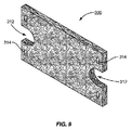
図9に示されるように、パッド300は柔軟で、通常、それぞれの短い端に半円状のカットアウト312をもつ長方形である。パッド300は、パッド300のそれぞれの短い端に、二穴のカットアウト314も含む。パッド300のそれぞれの端の穴314の間隔は、ツールヘッド200のピン212および214の間隔とそれぞれ同じである。
As shown in FIG. 9,
パッド装着機構210は、図4および5で示される開放位置から図6および7で示される半分閉じた位置、そして図2および8で示される閉鎖位置まで可変的に旋回する。この旋回機構210は、パッド300のヘッド200への取り付けおよびその取り外しを容易で効率的にする。特に、パッド装着機構210が開放位置(例えば、約130度を超えたところで充分に開いているが、約130度から270度の範囲)にある時、図10に示されるように、使用者は、ピン(212または214のどちらか)をパッド300の一方の端の穴314へ入れることにより、パッド300の一方の端をヘッド200へ取り付けることができる。使用者はその後、残っているピン(212または214のもう一方)をパッド300のもう一方の端の穴314へ入れることにより、パッド300のもう一方の端をヘッド200へ取り付けることができる。使用者はこのあと、パッド300をヘッド200へ固定するために、図11で示すとおり、パッド300がヘッド200の周りを完全に包むように、パッド装着機構210を閉鎖位置まで回す。パッド装着機構212の閉鎖位置への旋回動作(例えば、ピボットテンショナーを操作して)は、四面の清掃面(例えば、第一最上部、前部、底部、背部、第二最上部、その類似部、またはその組み合わせ)を作り出すため、ツールヘッド200の周りをしっかりと包むようにパッド300を締め付ける。ある態様において、それぞれのピン212、214は、パッド300を装着している間滑りを低減または防止しつつ、パッド300の穴314の座を作ってパッド300を定位置に保持するため、周辺面の高さよりも上へ突き出た小さな部分の突起213を含む。このように、パッド300は、取り付け時にもツールヘッド200に安全に保持される。
The
実施形態の態様において、パッド装着機構210は、ツールヘッド200から上方へ伸びる固定タブ216を含む固定機構により、閉鎖位置でしっかりと保持される。この固定タブ216は、パッド装着機構210にかかる定置圧から固定タブ216を解放するために使用者によってハンドル102のほうへ固定タブ216を物理的に押されない限りは、パッド装着機構210が動かないようにするリッジを含む。したがって、固定タブ216はパッド装着機構210をしっかり固定し動かなくするが、パッド装着機構210を容易に解放できるように充分柔軟である。上述のように、ツールヘッド200にパッド300を装着することにより、使用者はヘッド200にパッド300をすばやく固定でき、必要な場合のみパッド300を解放できる。
In an aspect of an embodiment, the
成形ハンドル102、ツールヘッド200、および複数の清掃面を作るためにヘッド200の周りを包むパッド300を含む上述のグリルツール100により、使用者は、安全で快適にグリルツール100の位置を調整して、グリル面を清掃することができる。本発明の実施形態のひとつの態様において、使用者は面から汚れを清掃するために、グリル面でグリルツール100を前後に動かす。本発明の実施形態のもうひとつの態様において、使用者は図12で示されるとおり、クラムシェルプラテングリル400の清掃にツール100を使用する。使用者は特に、蝶番で動くグリル400の上部や底部の狭い場所を清掃できる。上述のように、成形ハンドル102により、使用者は熱いグリル面402A、402Bに触れることなく、ツール100を奥まで入れることができる。図12に示される位置において、使用者は面から汚れを清掃するため、面402Aでツール100を前後に動かす。使用者がグリル面とグリル背部の交わる部分(例えば図12のアーチ状の隙間に見られる)で汚れを清掃するとき、前後の動きによってパッド300をグリルおよびグリル背面にぴったりと重ねるため、ツール100は図12で示される位置からパッド300の平面までほぼ垂直に90度回される。ここでは示されていないが、便利なことに、使用者はツール100を上下逆さまにして、面から汚れを除去するため面402Bで前後に動かしてもよい。さらに示されていないが、ツール100の側面が使用される際に追加の清掃面を提供するため、ツールヘッド200の側面202A、202B上で自由に曲がるパッド300のおかげで、使用者はグリル400の側面402Cを容易に清掃することもできる。
The
図13に示されるように、グリル400が壁際または他の厨房設備の隣に位置し、側面402Cと壁またはその他厨房設備の間のスペースに置かれている場合、ツール100は、パッド300の最上部前面および/または最上部背面が側面402Cと接触するように方向を調整できる。これらの面は、左側または右側の一面であると認識されよう。使用者はこの後、面から汚れを清掃するため面402Cで前後に動かす。このような状況における利点は、一例としてグリル面の範囲内、もうひとつの例としてクラムシェルグリルの上部プラテンの範囲内で事実上保持できるよう、ツール100の成形ハンドル102が設計されていることである。
As shown in FIG. 13, when the
本発明のグリルツールハンドル102には、グリル面の動作温度に耐えられるよう耐久性のある素材が使用されている。 The grill tool handle 102 of the present invention is made of a durable material that can withstand the operating temperature of the grill surface.
グリル面の動作温度は均一ではないと認識されよう。例えば、Garland Xpress XG-24 両面焼きグリドルの試験の結果(“Garland Xpress XG-24 Double-Sided Griddle Performance Test” Food Service Technology Center, San Ramon, CA, FSTC 報告書番号 5011.07.20, 2007 年 12 月出版、を本明細書において参照して援用する。ASTM F1605-95 (2001) Standard Test Method for Performance of Double-Sided Griddles を適用)、平均温度を約176℃(350°F)に設定した場合、グリル底面は約137℃(280°F)から約182℃(360°F)の範囲になることが分かっている。また例えば、AccuTemp Accu-Steam EG2083A36 電気グリドルの試験の結果(“AccuTemp Accu-Steam EG2083A36 Electric Griddle Performance Test” Food Service Technology Center, San Ramon, CA, FSTC 報告書番号 5011.05.18, 2005 年 12 月出版、を本明細書において参照して援用する。ASTM F1275-03 Standard Test Method for Performance of Griddles を適用)、平均温度を約190℃(375°F)に設定した場合、グリル面は約187℃(370°F)から約193℃(380°F)の範囲になることが分かっている。さらにまた例えば、Blodgett B36N TTT ガスグリドルの試験の結果(“Blodgett B36N-TTT Gas Griddle Performance Test” Food Service Technology Center, San Ramon, CA, FSTC 報告書番号 5011.04.02, 2004 年 8 月出版、を本明細書において参照して援用する。ASTM F1275-03 Standard Test Method for Performance of Griddles を適用)、平均温度を約190℃(375°F)に設定した場合、グリル面は約137℃(280°F)から約198℃(390°F)の範囲になることが分かっている。さらにまた例えば、Jade JGTSD ガスグリドルの試験の結果(“Jade JGTSD Gas Griddle Performance Test” Food Service Technology Center, San Ramon, CA, FSTC 報告書番号 5011.03.18, 2003 年 6 月出版、を本明細書において参照して援用する。ASTM F1275-03 Standard Test Method for Performance of Griddles を適用)、平均温度を約190℃(375°F)に設定した場合、グリル面は約157℃(315°F)から約201℃(395°F)の範囲になることが分かっている。したがって、本発明の実施形態の態様において、面の動作温度は約232℃(450゜F)またはそれ以上を含む。本発明の他の実施形態の態様において、面の動作温度は約137℃(280°F)から約232℃(450゜F)を含む。本発明の他の実施形態の態様において、面の動作温度は約157℃(315°F)から約221℃(430°F)を含む。本発明のまたさらに他の実施形態の態様において、面の動作温度は約171℃(340°F)から約205°C(400°F)を含む。 It will be appreciated that the operating temperature of the grill surface is not uniform. For example, Garland Xpress XG-24 double-sided griddle test results (“Garland Xpress XG-24 Double-Sided Griddle Performance Test” Food Service Technology Center, San Ramon, CA, FSTC report number 5011.07.20, December 2007 Publication, which is incorporated herein by reference, applies ASTM F1605-95 (2001) Standard Test Method for Performance of Double-Sided Griddles), and when the average temperature is set to about 176 ° C. (350 ° F.), The bottom surface of the grill has been found to be in the range of about 137 ° C (280 ° F) to about 182 ° C (360 ° F). Also, for example, the results of the AccuTemp Accu-Steam EG2083A36 Electric Griddle test (“AccuTemp Accu-Steam EG2083A36 Electric Griddle Performance Test” Food Service Technology Center, San Ramon, CA, FSTC report number 5011.05.18, published December 2005, In this specification, ASTM F1275-03 Standard Test Method for Performance of Griddles is applied), and when the average temperature is set to about 190 ° C. (375 ° F.), the grill surface is about 187 ° C. (370 ° C.). It has been found to be in the range from ° F) to about 193 ° C (380 ° F). Furthermore, for example, the results of the Blodgett B36N TTT gas griddle test (“Blodgett B36N-TTT Gas Griddle Performance Test”, Food Service Technology Center, San Ramon, CA, FSTC report number 5011.04.02, published August 2004) In the specification, ASTM F1275-03 Standard Test Method for Performance of Griddles is applied), and when the average temperature is set to about 190 ° C (375 ° F), the grill surface is about 137 ° C (280 ° F). ) To about 198 ° C. (390 ° F.). Furthermore, for example, the results of the Jade JGTSD Gas Griddle Performance Test (“Jade JGTSD Gas Griddle Performance Test”, Food Service Technology Center, San Ramon, CA, FSTC report number 5011.03.18, published June 2003) ASTM F1275-03 Standard Test Method for Performance of Griddles is applied), and when the average temperature is set to about 190 ° C (375 ° F), the grill surface is about 157 ° C (315 ° F) to about It has been found to be in the range of 201 ° C (395 ° F). Thus, in aspects of embodiments of the present invention, the operating temperature of the surface includes about 232 ° C. (450 ° F.) or higher. In aspects of other embodiments of the present invention, the operating temperature of the surface includes from about 137 ° C. (280 ° F.) to about 232 ° C. (450 ° F.). In aspects of other embodiments of the present invention, the operating temperature of the surface includes from about 157 ° C. (315 ° F.) to about 221 ° C. (430 ° F.). In an aspect of yet another embodiment of the present invention, the operating temperature of the surface includes from about 171 ° C. (340 ° F.) to about 205 ° C. (400 ° F.).
実施形態の態様において、ツールヘッドは第一材料を使用して作られ、ツールハンドルは第二材料を使用して作られるが、第一材料は第二材料よりも高い温度に耐えることができる。ひとつの態様において、第一材料および第二材料は射出成形が可能なポリマーである。もうひとつの態様において、射出成形が可能なポリマーは熱可塑性ポリマー、熱硬化性ポリマー、その合金、そのコポリマー、その混合物、そのコンポジット、またはその化合物のいずれかである。さらに他の態様において、射出成形が可能なポリマーはポリスチレン、アクリロニトリルブタジエンスチレン(ABS)、ポリアミド、ポリオレフィン、その合金、そのコポリマー、その混合物、そのコンポジット、またはその化合物のいずれかである。またさらに他の態様において、第一材料はナイロン(例えば、ナイロン6,6および/またはpH最大約12.2以上に耐えることができるもの)、その合金、そのコポリマー、その混合物、そのコンポジット、またはその化合物で、第二材料はポリプロピレン、ポリエチレン、塩化ポリビニール(PVC)、その合金、そのコポリマー、その混合物、そのコンポジット、またはその化合物のいずれかである。 In aspects of embodiments, the tool head is made using a first material and the tool handle is made using a second material, but the first material can withstand higher temperatures than the second material. In one embodiment, the first material and the second material are injection moldable polymers. In another embodiment, the injection moldable polymer is either a thermoplastic polymer, a thermosetting polymer, an alloy thereof, a copolymer thereof, a mixture thereof, a composite thereof, or a compound thereof. In yet other embodiments, the injection moldable polymer is any of polystyrene, acrylonitrile butadiene styrene (ABS), polyamide, polyolefin, alloys thereof, copolymers thereof, mixtures thereof, composites, or compounds thereof. In still yet other embodiments, the first material is nylon (eg, nylon 6,6 and / or one that can withstand a pH up to about 12.2 or higher), an alloy thereof, a copolymer thereof, a mixture thereof, a composite thereof, or In that compound, the second material is either polypropylene, polyethylene, polyvinyl chloride (PVC), its alloy, its copolymer, its mixture, its composite, or its compound.
態様において、パッド300は、金属素材、重合体素材、天然素材またはその混合物のいずれかである。もうひとつの態様において、パッド300は、織物素材、不織素材、またはその混合物のいずれかである。さらに別の態様において、パッド300はさらに研磨材を含む。例えば、その目的上、パッド300は、ニッケルメッキ面のようなグリル面を損傷したり傷つけたりしない特徴をもつ、フェノール樹脂と結合したポリアミド繊維(例えば、その合金、そのコポリマー、その混合物、そのコンポジット、またはその化合物を含む)を使用して作られた不織材料であり、約232℃(450゜F)以上の温度での使用に適し、腐蝕性洗浄組成物(例えば、pH最大約12.2以上)や類似物、またはその混合物との使用が可能である。パッド300に適した材料の例は、3M Commercial Care Division(ミネソタ州セントポール)から出ている、2004年度版SCOTCH-BRITE(登録商標)清掃製品カタログに掲載されている製品群、またはSaint-Gobain Abrasives, Inc.(マサチューセッツ州ウースター)から出ている、製品カタログのBEAR-TEX(登録商標)面仕上げ製品の項に掲載されているハンドパッド製品群、またはStandard Abrasives, Inc.(カリフォルニア州シーミバレー)からBRITERITE(登録商標)の商標名で発売されているハンドパッド製品群を含むが、これらに限定されるものではない。これらの製品は型抜きである。またさらに別の態様において、パッド300はさらに洗浄組成物を含む。
In an embodiment,
パッド300は、汚れ面を清掃する間グリル面の動作温度にも耐えられる、研磨材を含まない清掃用パッドである。本発明の実施形態のひとつの態様において、パッド300の厚みは約1.27cm(1/2インチ)である。実施形態の追加の態様において、パッドは細目デニールのナイロン繊維である。実施形態のさらに別の態様において、パッド300は約0.635cm(0.25インチ)の曲げ半径で180度曲げることができる。
The
操作例以外の箇所において、または別段の指定がある箇所を除き、本明細書および特許請求で使用される、成分、反応条件、およびその他の数量を表すすべての数字は、「約」という用語によってすべての例に修正が加えられることを理解されたい。したがって、反対の指示がない限り、以下の明細書および添付の特許請求で示される数値パラメーターは、本発明の実施形態の態様および/または実施形態をもって取得しようとする所望の特性に応じて変化する近似値である。最低に見積もっても、また特許請求の範囲と同等の見解の適用を限定するものでもなく、それぞれの数値パラメーターは有効数字および通常の丸め近似値の数の観点で解釈されるべきである。 Unless otherwise specified, or where otherwise specified, all numbers representing ingredients, reaction conditions, and other quantities used in the specification and claims are in accordance with the term “about”. It should be understood that all examples will be modified. Accordingly, unless indicated to the contrary, the numerical parameters set forth in the following specification and attached claims will vary depending on the aspects of the embodiments of the invention and / or the desired properties sought to be obtained with the embodiments. It is an approximate value. Neither the lowest estimate nor the application of the equivalent view of the claims is intended, and each numerical parameter should be interpreted in terms of significant figures and the number of normal rounding approximations.
本発明の広義の範囲を示す数的範囲および数値パラメーターは近似値であるにもかかわらず、特定例において示される数値は可能な限り精確に報告されている。しかしながら、いずれの数値も、それぞれの試験計測で得られた標準偏差に起因する一定の誤りを必然的かつ本質的に含む。 Although the numerical ranges and numerical parameters indicating the broad scope of the present invention are approximate, the numerical values shown in the specific examples are reported as accurately as possible. Any numerical value, however, inherently contains certain errors necessarily resulting from the standard deviation found in their respective testing measurements.
本発明の実施形態の態様に一致して作られたグリルツール100が、グリル面の清掃時に受ける熱にどの程度耐えられるかを確定するために、いくつかの試験が行われた。とりわけ、本発明の実施形態の態様に一致して作られたグリルツール100のツールヘッド200が、グリル面の清掃時に受ける熱にどの程度耐えられるかを確定するために、いくつかの試験がおこなわれた。態様において、グリルツールは、クイックサービスレストラン産業において使用されるプラテン面(例えば、米国特許第 7082941 号、米国特許第 2006/0201495 号、米国特許第 2007/0254078 号、および米国特許第 2007/0251518 号に開示される3つのプラテングリルを含むが、これらに限定されるものではない)のようなグリル面の清掃用である。このようなグリル面を清掃するために、最大約45分かかることが観察された。
Several tests were conducted to determine how much the
その結果、グリルツール100には、付随する熱への暴露に対する耐性が望まれる。ヘッド200は約260°C(500°F)で溶解するポリアミド 6/6 (例えば、Solutia Inc. 社(米国ミズーリ州セントルイス)のVydyne(登録商標)21SPF/21SPG ポリアミド66樹脂参照)および UL94 規格適合のV-2(例えば、Underwriters Laboratories Inc. 社の UL 94 規格の装置および器具部品用のプラスチック材料燃焼性試験参照 <http://www.ides.com/property descriptions/UL94.asp>、<http://www.fire testing.com/html/instruments/ul94ad.htm>、および <http://ulstandardsinfonet.ul.com/scopes/0094.html>)から成形された。高温耐久性はハンドル102材料の選択における任意の特性である。ほとんどないことであるが、ハンドル102がプラテンに接触しても、静観していられる。したがって、ポリプロピレン(例えば、Lyondell Chemical Company 社(オランダ・ロッテルダム)の PRO-FAXTM 8523 超高耐衝撃性ポリプロピレンコポリマー樹脂を参照)がハンドル102用素材として選択された。
As a result, the
選択された材料は両方とも旧モデルのグリルツール10に使用された。グリルツール10に関連して唯一記録された熱に関する問題は、付属する小さなフックおよび環が溶けたことである。この結果、時間の経過と共に、グリルツール10は清掃パッドを掴む能力を失った。付属物が薄かったため、ポリアミド66樹脂に対する設定温度に耐性を提供することができなかった。グリルツール100の設計において、薄型の特徴は避けられた。
Both selected materials were used in the older
グリルツール100が熱ストレス環境でどの程度作動するかを確定するために、異素材偶発的接触試験が行われた。これらの試験は、ツールヘッド200の第一面204、ツールヘッド200の第一またはフロントエンド202C、ハンドル102の第一カップリングメンバー208A(例えば、図4および図6の部材番号208Aから線に沿って接触している面)が熱せられた面への偶発的接触にどの程度耐えられるかを検証した。さらなる詳細は以下の節で述べられている。
In order to determine how well the
偶発的接触試験の目的は、グリルツール100について、熱い面とグリルツール100の特定部分を短時間接触させた際の影響を試験することにあった。232℃(450°F)に熱せられたホットプレート(Cole-Parmer Instrument Co.(イリノイ州シカゴ)の 04644 シリーズデジタルホットプレート/撹拌機モデル#731)の面に、特定部分を30秒間接触させた。熱したホットプレートに接触させた特定部分は、ツールヘッド200の第一面204、ツールヘッド200の第一またはフロントエンド202C、およびハンドル102の第一カップリングメンバー208Aの底面(例えば、図4および図6の部材番号208Aから線に沿って接触している面を参照)である。それぞれのグリルツール100を一度冷却してから、加圧後、落下試験を行い、評価した。ツールヘッド200の第一またはフロントエンド202Cを面に置いた状態で、それぞれのグリルツール100にはハンドル102の方向へ手で下向きの力を加えることにより、加圧負荷をかけた。その後、同じ位置のまま、それぞれのグリルツール100をおよそ4フィートの高さから3回手で落とした。それぞれのグリルツール100は、最終的に割れや歪み、あるいは他の熱による劣化がないか検査された。
The purpose of the accidental contact test was to test the effect of a hot contact with a specific portion of the
いくつかのグリルツール100は、232℃(450°F)で30秒間という条件下、別の位置で試験された。最初の位置において、3個のグリルツール100が試験され、ツールヘッド200の第一面204がホットプレート面に密着するようにした。熱は、ポリプロピレンハンドル102の先端に付いた残滓をわずかに溶かすほど充分高温だった。それを除き、熱の影響は最小だった。グリルツール100は加圧試験にすべて合格した。落下試験に合格しなかったのは、1個のグリルツール100のみであった。衝撃により、ハンドル102は2箇所破損した。それは、ハンドル102の底面、および第一カップリングメンバー208Aの一部(例えば、図4および図6の部材番号208Aから線に沿って接触している面)である。第二の位置において、2個のグリルツール100が試験され、ツールヘッド200の第一またはフロントエンド202Cがホットプレート面に寄りかかるようにした。熱暴露に起因する顕著な影響はなかった。グリルツール100は加圧試験と落下試験の両方に合格した。最後の位置は、ホットプレート面に、1個のグリルツール100のハンドル102を置いておくものである。ハンドル102は接触部が明らかに溶けた。
Some
説明の目的で実施形態の主な態様および/または実施形態を示してきたが、先の記述および添付図面は本発明の範囲を限定するものとみなされるものではない。したがって、様々な改変、改作、および代替物が、本発明の意図と範囲から逸脱することなく、当業者に見い出される可能性がある。例として、装着機構210のピボットテンショナー211がツールヘッド200のバックエンド202Dまたはフロントエンド202Cの一方にあり、ツールヘッドピン212がツールヘッド200のバックエンド202Dまたはフロントエンド202Cのもう一方にある可能性がある。代わりに、装着機構210がツールヘッド200のバックエンド202Dおよびフロントエンド202Cのそれぞれにピボットテンショナーを含むことがある。さらなるバリエーションにおいて、装着機構210が、フロントおよび/またはバックではなく、1箇所以上のサイドにあることがある。また、固定機構216は固定タブよりむしろ、図5、7、8、および10で示され呼称される回転機構である。いずれのタイプの固定機構216も、ツールヘッド200にパッド300を固定すると同時に、清掃されるグリル面403A、403B、403Cに接触するパッド300の清掃面または作用面(例えば、第一最上部、前部、底部、背部、第二最上部、その類似部、またはその組み合わせ)の能力を阻害しないことは、評価されよう。さらにツールヘッド200が、ツールハンドル102にしっかり固定できて、取り外しができることは評価されよう。かかる例において、異なるタスクに対する代替ヘッド(例えば、スキージーヘッド、スクレーパーヘッド、その類似物、またはその組み合わせ)は交換可能であり、ツールハンドル102に確実に装着できる。また、安全性に関連する1つ以上の特徴は、食品調理および/または食品調理機器の保守を専門としたツール100が、その機能を変わらず保持することを保証するものである。
簡潔性と可読性を目的として、このようなすべての改変および改良は本明細書で削除されているものの、以下の請求の範囲内に適切に含まれることを理解されたい。
Although the main aspects and / or embodiments of the embodiments have been shown for illustrative purposes, the foregoing description and accompanying drawings are not to be construed as limiting the scope of the invention. Accordingly, various modifications, adaptations, and alternatives may be found to those skilled in the art without departing from the spirit and scope of the present invention. As an example, the pivoting tensioner 211 of the mounting
It should be understood that all such modifications and improvements have been deleted herein for purposes of brevity and readability, but are properly included within the scope of the following claims.
100 グリルツール
102 ハンドル
102A 第二ハンドグリップまたは第二エンドハンドル部のロケーション
102A' 第二エンドハンドル部
102B 延長ハンドル部
102C 第一ハンドグリップまたは中間ハンドル部のロケーション
102C′ 中間ハンドル部
102D ハンドルリッジまたは隆起部
102E 第一エンドハンドル部
104 きめエリアまたは部分
106 収納部
200 ツールヘッド
202A ツールヘッド側面
202B ツールヘッド側面
202C ツールヘッドの第一またはフロントエンド
202D ツールヘッドの第二またはリアエンド
204 第一面
206 対向面
208A 第一カップリングメンバー
208B 装着機構
210 装着機構
211 ピボットテンショナー
212 ツールヘッドピン
213 突起部
214 装着機構ピン
216 固定機構(例えば、固定タブ)
300 パッド
302 大きな清掃面
304 小さな清掃面
306 小さな清掃面
310 小さな清掃面
312 カットアウト(例えば、半円状カットアウト)
314 穴
400 クラムシェルプラテングリル
402A プラテングリル面またはグリルプレート面
402B プラテングリル面またはグリルプレート面
402C プラテングリル側面
DESCRIPTION OF
300
314
Claims (7)
底面と、該底面の反対側の上面とを有するツールヘッドであって、清掃パッドによって前記底面の全体および前記上面の一部を覆うように前記ツールヘッドに清掃パッドを着脱自在に取り付ける装着機構を含むツールヘッドと、
前記ツールヘッドの上面に連結されたツールハンドルとを具備し、
前記ツールヘッドの上面には、前記ツールハンドルを前記ツールヘッドに取り付けるための第一カップリングメンバーが設けられており、
前記ツールハンドルは、第一ハンドルエンドと、該第一ハンドルエンドの反対側の第二ハンドルエンドとを有しており、
前記ツールハンドルは、更に、
前記第一カップリングメンバーと係合して前記ツールヘッドを取り外しができるよう固定するための第二カップリングメンバーが設けられ前記第一ハンドルエンドから上方に伸びる第一エンドハンドル部と、
前記第一エンドハンドル部に連結され後方へ斜め上方に伸び第一ハンドグリップを有した中間ハンドル部と、
前記中間ハンドル部に連結され、前記中間ハンドル部よりも急な角度で斜め上方に後方へ伸びる延長ハンドル部と、
前記延長ハンドル部に連結され、前記第二ハンドルエンドへ向けて後方へ斜め下方に伸び第二ハンドグリップを有した第二ハンドルエンド部とを備えているグリル清掃ツール。 In the grill cleaning tool for cleaning the surface of the grill,
A tool head having a bottom surface and an upper surface opposite to the bottom surface, the mounting mechanism detachably attaching the cleaning pad to the tool head so as to cover the entire bottom surface and a part of the upper surface by the cleaning pad. Including a tool head;
A tool handle coupled to the upper surface of the tool head ;
A first coupling member for attaching the tool handle to the tool head is provided on the upper surface of the tool head,
The tool handle has a first handle end and a second handle end opposite the first handle end;
The tool handle further comprises:
A first end handle portion provided with a second coupling member for engaging with the first coupling member to fix the tool head so that the tool head can be removed, and extending upward from the first handle end;
An intermediate handle portion connected to the first end handle portion and extending obliquely upward to the rear and having a first hand grip;
An extended handle portion connected to the intermediate handle portion and extending rearward obliquely upward at a steeper angle than the intermediate handle portion;
A grill cleaning tool, comprising: a second handle end portion coupled to the extension handle portion and extending obliquely downward rearward toward the second handle end and having a second hand grip .
Applications Claiming Priority (3)
| Application Number | Priority Date | Filing Date | Title |
|---|---|---|---|
| US4445408P | 2008-04-11 | 2008-04-11 | |
| US61/044,454 | 2008-04-11 | ||
| PCT/IB2009/051529 WO2009125376A1 (en) | 2008-04-11 | 2009-04-10 | Grill tool, associated pad, and associated methods |
Publications (3)
| Publication Number | Publication Date |
|---|---|
| JP2011517621A JP2011517621A (en) | 2011-06-16 |
| JP2011517621A5 JP2011517621A5 (en) | 2013-12-12 |
| JP5491494B2 true JP5491494B2 (en) | 2014-05-14 |
Family
ID=41161589
Family Applications (1)
| Application Number | Title | Priority Date | Filing Date |
|---|---|---|---|
| JP2011503542A Active JP5491494B2 (en) | 2008-04-11 | 2009-04-10 | Grill tool, associated pad, and associated method |
Country Status (9)
| Country | Link |
|---|---|
| US (1) | US8671500B2 (en) |
| EP (2) | EP2997874B1 (en) |
| JP (1) | JP5491494B2 (en) |
| CN (2) | CN101980653B (en) |
| AU (1) | AU2009235043B2 (en) |
| CA (1) | CA2718657C (en) |
| ES (1) | ES2641719T3 (en) |
| MX (1) | MX2010010976A (en) |
| WO (1) | WO2009125376A1 (en) |
Families Citing this family (15)
| Publication number | Priority date | Publication date | Assignee | Title |
|---|---|---|---|---|
| US8539633B1 (en) * | 2009-04-14 | 2013-09-24 | Tim S. Langley | Gutter applicator |
| US20110225755A1 (en) * | 2010-03-18 | 2011-09-22 | Ecolab Usa Inc. | Cleaning tool |
| US9161612B2 (en) * | 2011-11-30 | 2015-10-20 | Grillbot, Llc | Surface-cleaning device |
| US9408522B2 (en) | 2012-03-09 | 2016-08-09 | 3M Innovative Properties Company | Fryer cleaning tool with cleaning head with cleaning pad slidably mountable thereon |
| US8479346B1 (en) | 2012-07-18 | 2013-07-09 | Puthalath Koroth Raghuprasad | Splatter-free grill cleaner |
| US9775486B2 (en) | 2012-11-09 | 2017-10-03 | 3M Innovative Properties Company | Cleaning pad with support body |
| WO2015077422A2 (en) * | 2013-11-20 | 2015-05-28 | Mcmann Larry R Jr | Cleaning tool |
| AU2015217476B2 (en) * | 2014-02-17 | 2018-02-08 | Ames Tools Corporation | Handle assembly for drywall finisher box |
| US10286423B1 (en) * | 2015-04-03 | 2019-05-14 | David Armetta | Grill grate cleaning tool and heat shield |
| CA3014890A1 (en) | 2016-02-17 | 2017-08-24 | Ecolab Usa Inc. | Cleaning tool with removable sock |
| US10500709B2 (en) * | 2016-08-29 | 2019-12-10 | Grill Grubber, Llc | Pad handle assembly |
| WO2019033217A1 (en) * | 2017-08-18 | 2019-02-21 | Joseph Norris | Tool for cleaning a grill |
| USD855918S1 (en) * | 2018-05-22 | 2019-08-06 | George C Prior | Cleaning and raking apparatus for grills |
| USD979872S1 (en) * | 2021-01-25 | 2023-02-28 | Charles C. Lovell | Baseball bat barbeque scraper |
| US11759083B2 (en) * | 2021-09-03 | 2023-09-19 | Jordan Kahn Company | Grill cleaning pad |
Family Cites Families (60)
| Publication number | Priority date | Publication date | Assignee | Title |
|---|---|---|---|---|
| US2657413A (en) * | 1950-07-06 | 1953-11-03 | Orrice L Murdock | Cleaning device |
| US3412416A (en) * | 1967-07-31 | 1968-11-26 | Minnesota Mining & Mfg | Sponge mophead and attaching clips |
| US4023312A (en) * | 1975-09-08 | 1977-05-17 | Stickney Jon O | Grill cleaning apparatus |
| JPS5472857U (en) * | 1977-11-01 | 1979-05-24 | ||
| JPS5744938Y2 (en) * | 1979-12-28 | 1982-10-04 | ||
| USD300478S (en) * | 1985-12-23 | 1989-03-28 | Airwick Industries, Inc. | Scouring pad |
| US5060343A (en) * | 1986-01-31 | 1991-10-29 | Philip Nisenbaum | Tool handle |
| US5054830A (en) * | 1986-01-31 | 1991-10-08 | Philip Nisenbaum | Shovel |
| US5165144A (en) * | 1986-01-31 | 1992-11-24 | Philip Nisenbaum | Tool handle and angularly adjustable attachment |
| US4828427A (en) * | 1986-01-31 | 1989-05-09 | Phillip Nisenbaum | Cement screed tool |
| US5025596A (en) * | 1988-09-13 | 1991-06-25 | Minnesota Mining And Manufacturing Company | Hand scouring pad |
| SE8903241D0 (en) * | 1989-10-03 | 1989-10-03 | Electrolux Ab | Mop Frames |
| US5134746A (en) * | 1989-12-11 | 1992-08-04 | Steven William | Cleaning material |
| EP0656080B1 (en) * | 1992-08-24 | 1996-09-18 | Minnesota Mining And Manufacturing Company | Melt bonded nonwoven articles and methods of preparing same |
| US5765256A (en) * | 1993-08-19 | 1998-06-16 | Minnesota Mining And Manufacturing Company | Nonwoven cleaning brush |
| US5373600A (en) * | 1993-11-09 | 1994-12-20 | Stojanovski; Stojan | Grill scraper and cleaner |
| JPH07236609A (en) * | 1994-03-01 | 1995-09-12 | Yukinobu Toda | Tub washing tool |
| US5471700A (en) * | 1994-12-08 | 1995-12-05 | Pereira; Camilo | Handle for grill cleaning tools |
| USD365897S (en) * | 1994-12-08 | 1996-01-02 | Camilo Pereira | Grill scraper |
| USD384566S (en) * | 1994-12-29 | 1997-10-07 | Dickhaus & Partner Gmbh | Handle for tools |
| US5626512A (en) * | 1995-05-04 | 1997-05-06 | Minnesota Mining And Manufacturing Company | Scouring articles and process for the manufacture of same |
| US6141813A (en) * | 1995-06-07 | 2000-11-07 | Micronova Manufacturing Inc. | Self-wringing mop and wringer assembly, cleaning element assembly and cleaning element for use with same |
| US6058552A (en) * | 1997-06-10 | 2000-05-09 | Hanan; Abraham | Mop having hold down bars for removably securing an absorbent piece of material thereto |
| CN2325647Y (en) * | 1997-07-02 | 1999-06-23 | 徐敬党 | Baking apparatus |
| JP2984242B2 (en) * | 1997-11-18 | 1999-11-29 | 広人 大熊 | Bleach-containing fiber mop |
| USD410308S (en) * | 1998-04-01 | 1999-05-25 | Vileda Gmbh | Scrubbing pad |
| JP2000041934A (en) | 1998-08-03 | 2000-02-15 | Azuma Kogyo Kk | Washing device for tableware |
| USD420183S (en) * | 1998-09-30 | 2000-02-01 | Vileda Gmbh | Scrubbing pad |
| US6065178A (en) * | 1998-11-18 | 2000-05-23 | Hsieh; Ming Ti | Separate type sponge mop |
| US6216306B1 (en) * | 1999-08-13 | 2001-04-17 | The Coleman Company, Inc. | Grill cleaning brush and scraper |
| US7150063B1 (en) * | 2000-03-14 | 2006-12-19 | Scott Graham | Vehicle wash mitt |
| USD457698S1 (en) * | 2000-04-07 | 2002-05-21 | 3M Innovative Properties Company | Scouring pad |
| US6571419B1 (en) * | 2000-05-12 | 2003-06-03 | Chien-Chan Enterprise Co., Ltd. | Mop with a sucking plate and a mop unit having changeable soft and coarse sponge sides |
| JP2002017648A (en) * | 2000-07-07 | 2002-01-22 | Tomoe Dainingu:Kk | Kitchen brush holder |
| USD462150S1 (en) * | 2001-04-11 | 2002-08-27 | The Clorox Company | Cleaning pad |
| USD473027S1 (en) * | 2001-09-25 | 2003-04-08 | 3M Innovative Properties Company | Sponge |
| AT411566B (en) * | 2002-01-11 | 2004-03-25 | Engl Johannes | FLOOR CLEANING EQUIPMENT |
| USD521200S1 (en) * | 2002-01-18 | 2006-05-16 | Prince Castle Inc. | Grill scraper |
| US6871377B2 (en) * | 2002-01-18 | 2005-03-29 | Prince Castle Inc. | Grill scraper |
| JP2003310515A (en) | 2002-04-26 | 2003-11-05 | Vitacraft Japan Kk | Cleaning tool |
| US6760949B2 (en) * | 2002-09-04 | 2004-07-13 | Bruce Kaminstein | Rotating dish brush |
| USD480852S1 (en) * | 2002-06-18 | 2003-10-14 | Financiere Elysees Balzac | Sponge |
| US7082941B2 (en) * | 2002-10-22 | 2006-08-01 | The Garland Group | Grill with independent heating zones |
| CN2582448Y (en) * | 2002-12-16 | 2003-10-29 | 张综源 | Multipurpose brush |
| US6916382B1 (en) * | 2003-03-04 | 2005-07-12 | Grate Chef, Llc | Wipe pad for cooking grill |
| CN1537681A (en) * | 2003-10-23 | 2004-10-20 | 慧 顾 | Contrllable liquid spraying cleaning brush |
| US6966094B1 (en) * | 2003-10-24 | 2005-11-22 | Rigakos Fotios G | Grill cleaning brush and scraper |
| US7812077B2 (en) * | 2003-12-17 | 2010-10-12 | Sabic Innovative Plastics Ip B.V. | Polyester compositions, method of manufacture, and uses thereof |
| JP3108660U (en) * | 2004-08-12 | 2005-04-28 | 稔 向後 | S-shaped universal pattern |
| USD506587S1 (en) * | 2004-10-15 | 2005-06-21 | John W. Armaly, Jr. | Grill cleaning sponge |
| USD548414S1 (en) * | 2004-12-29 | 2007-08-07 | Continental Commercial Products, Llc | Scrubber |
| US20060207042A1 (en) * | 2005-03-09 | 2006-09-21 | Brett Di Paolo | Grill scrubbing device |
| KR101071635B1 (en) * | 2005-09-01 | 2011-10-10 | 가부시키가이샤 산코 | Cleaning brush |
| US20070130713A1 (en) * | 2005-12-14 | 2007-06-14 | Kimberly-Clark Worldwide, Inc. | Cleaning wipe with textured surface |
| USD556966S1 (en) * | 2005-12-14 | 2007-12-04 | 3M Innovative Properties Company | Scouring article |
| ES2455522T3 (en) * | 2006-03-10 | 2014-04-15 | 3M Innovative Properties Company | Cleaning pad for hot food preparation surfaces |
| CN101044967B (en) * | 2006-03-31 | 2010-12-15 | 3M创新有限公司 | Cleaning device with multiple cleaning sides |
| US7878109B2 (en) * | 2006-04-28 | 2011-02-01 | Restaurant Technology, Inc. | Automated dual cooking surface grill |
| US7913615B2 (en) * | 2006-04-28 | 2011-03-29 | Restaurant Technology, Inc. | Automated dual cooking surface grill and method |
| US20070270088A1 (en) * | 2006-05-18 | 2007-11-22 | Acs Industries | Grill and griddle cleaning device |
-
2009
- 2009-04-08 US US12/420,479 patent/US8671500B2/en active Active
- 2009-04-10 AU AU2009235043A patent/AU2009235043B2/en active Active
- 2009-04-10 EP EP15191901.6A patent/EP2997874B1/en active Active
- 2009-04-10 EP EP20090731352 patent/EP2299893A4/en not_active Withdrawn
- 2009-04-10 MX MX2010010976A patent/MX2010010976A/en active IP Right Grant
- 2009-04-10 CN CN200980111701XA patent/CN101980653B/en active Active
- 2009-04-10 CA CA2718657A patent/CA2718657C/en active Active
- 2009-04-10 WO PCT/IB2009/051529 patent/WO2009125376A1/en active Application Filing
- 2009-04-10 JP JP2011503542A patent/JP5491494B2/en active Active
- 2009-04-10 CN CN201210336352.5A patent/CN103082880B/en not_active Expired - Fee Related
- 2009-04-10 ES ES15191901.6T patent/ES2641719T3/en active Active
Also Published As
| Publication number | Publication date |
|---|---|
| US8671500B2 (en) | 2014-03-18 |
| CN101980653B (en) | 2013-09-18 |
| EP2299893A1 (en) | 2011-03-30 |
| US20090255075A1 (en) | 2009-10-15 |
| CN103082880B (en) | 2015-07-29 |
| ES2641719T3 (en) | 2017-11-13 |
| JP2011517621A (en) | 2011-06-16 |
| MX2010010976A (en) | 2010-10-26 |
| WO2009125376A1 (en) | 2009-10-15 |
| EP2997874B1 (en) | 2017-08-23 |
| AU2009235043B2 (en) | 2014-06-05 |
| CN103082880A (en) | 2013-05-08 |
| CA2718657C (en) | 2017-10-17 |
| AU2009235043A1 (en) | 2009-10-15 |
| EP2299893A4 (en) | 2013-07-10 |
| EP2997874A1 (en) | 2016-03-23 |
| CN101980653A (en) | 2011-02-23 |
| CA2718657A1 (en) | 2009-10-15 |
Similar Documents
| Publication | Publication Date | Title |
|---|---|---|
| JP5491494B2 (en) | Grill tool, associated pad, and associated method | |
| US8032974B2 (en) | Grill cleaning apparatus | |
| US9408522B2 (en) | Fryer cleaning tool with cleaning head with cleaning pad slidably mountable thereon | |
| US9775486B2 (en) | Cleaning pad with support body | |
| JP2008535633A (en) | Cleaning tool | |
| KR20070048242A (en) | Mop having scrubbing area | |
| BR112020020126A2 (en) | SHAVING OR SHAVING APPLIANCE HANDLE WITH AN ARTICULATED PORTION | |
| JP2009536072A (en) | Hood mill with removable blade assembly | |
| US20180206622A1 (en) | Cleaning brush | |
| WO2017068862A1 (en) | Air conditioner | |
| US10602904B2 (en) | Cleaning tool with chainmail abrader | |
| US11234575B2 (en) | Sorbent mop base assembly and methods related thereto | |
| JP2007044088A (en) | Handy mop | |
| WO2008113002A1 (en) | Cleaning utensil with flexible peripheral regions | |
| WO2005092171A1 (en) | Cleaning tool and holding member used for the same | |
| CN104203044B (en) | There is the oral care implement of flexible shank | |
| CA2727394A1 (en) | Fan-shaped grater for foodstuffs | |
| US11744432B1 (en) | Adjustable dusting tool and related method | |
| JP2020512869A (en) | Floor nozzle for steam cleaner | |
| US20050115008A1 (en) | Combination floor & ergonomic hand held cleaning tools | |
| KR102099185B1 (en) | Dexterity test device for glove and dexterity test assembly for glove | |
| US20070251098A1 (en) | Multi-function pizza tool | |
| JP2005218615A (en) | Cleaner | |
| JP2021115243A (en) | Cleaning tool | |
| TWM585578U (en) | Multi-purpose food processing kitchenware |
Legal Events
| Date | Code | Title | Description |
|---|---|---|---|
| A521 | Request for written amendment filed |
Free format text: JAPANESE INTERMEDIATE CODE: A523 Effective date: 20120406 |
|
| A621 | Written request for application examination |
Free format text: JAPANESE INTERMEDIATE CODE: A621 Effective date: 20120406 |
|
| A977 | Report on retrieval |
Free format text: JAPANESE INTERMEDIATE CODE: A971007 Effective date: 20130705 |
|
| A131 | Notification of reasons for refusal |
Free format text: JAPANESE INTERMEDIATE CODE: A131 Effective date: 20130723 |
|
| A524 | Written submission of copy of amendment under article 19 pct |
Free format text: JAPANESE INTERMEDIATE CODE: A524 Effective date: 20131022 |
|
| TRDD | Decision of grant or rejection written | ||
| A01 | Written decision to grant a patent or to grant a registration (utility model) |
Free format text: JAPANESE INTERMEDIATE CODE: A01 Effective date: 20140128 |
|
| A61 | First payment of annual fees (during grant procedure) |
Free format text: JAPANESE INTERMEDIATE CODE: A61 Effective date: 20140227 |
|
| R150 | Certificate of patent or registration of utility model |
Ref document number: 5491494 Country of ref document: JP Free format text: JAPANESE INTERMEDIATE CODE: R150 |
|
| R250 | Receipt of annual fees |
Free format text: JAPANESE INTERMEDIATE CODE: R250 |
|
| R250 | Receipt of annual fees |
Free format text: JAPANESE INTERMEDIATE CODE: R250 |
|
| R250 | Receipt of annual fees |
Free format text: JAPANESE INTERMEDIATE CODE: R250 |
|
| R250 | Receipt of annual fees |
Free format text: JAPANESE INTERMEDIATE CODE: R250 |
|
| R250 | Receipt of annual fees |
Free format text: JAPANESE INTERMEDIATE CODE: R250 |
|
| R250 | Receipt of annual fees |
Free format text: JAPANESE INTERMEDIATE CODE: R250 |
|
| R250 | Receipt of annual fees |
Free format text: JAPANESE INTERMEDIATE CODE: R250 |
|
| R250 | Receipt of annual fees |
Free format text: JAPANESE INTERMEDIATE CODE: R250 |