JP5486400B2 - Power saving line interactive uninterruptible power supply - Google Patents
Power saving line interactive uninterruptible power supply Download PDFInfo
- Publication number
- JP5486400B2 JP5486400B2 JP2010114259A JP2010114259A JP5486400B2 JP 5486400 B2 JP5486400 B2 JP 5486400B2 JP 2010114259 A JP2010114259 A JP 2010114259A JP 2010114259 A JP2010114259 A JP 2010114259A JP 5486400 B2 JP5486400 B2 JP 5486400B2
- Authority
- JP
- Japan
- Prior art keywords
- power
- charge
- switch
- battery
- bridge switching
- Prior art date
- Legal status (The legal status is an assumption and is not a legal conclusion. Google has not performed a legal analysis and makes no representation as to the accuracy of the status listed.)
- Active
Links
- 230000002452 interceptive effect Effects 0.000 title claims description 22
- 238000004804 winding Methods 0.000 claims description 14
- 238000007599 discharging Methods 0.000 claims description 4
- 230000005669 field effect Effects 0.000 claims description 2
- 229910044991 metal oxide Inorganic materials 0.000 claims description 2
- 150000004706 metal oxides Chemical class 0.000 claims description 2
- 238000010586 diagram Methods 0.000 description 5
- 230000007423 decrease Effects 0.000 description 3
- 238000006243 chemical reaction Methods 0.000 description 2
- 230000005611 electricity Effects 0.000 description 2
- 230000002159 abnormal effect Effects 0.000 description 1
- 230000005856 abnormality Effects 0.000 description 1
- 230000002457 bidirectional effect Effects 0.000 description 1
- 230000003247 decreasing effect Effects 0.000 description 1
- 230000000694 effects Effects 0.000 description 1
Images


Classifications
-
- H—ELECTRICITY
- H02—GENERATION; CONVERSION OR DISTRIBUTION OF ELECTRIC POWER
- H02J—CIRCUIT ARRANGEMENTS OR SYSTEMS FOR SUPPLYING OR DISTRIBUTING ELECTRIC POWER; SYSTEMS FOR STORING ELECTRIC ENERGY
- H02J9/00—Circuit arrangements for emergency or stand-by power supply, e.g. for emergency lighting
- H02J9/04—Circuit arrangements for emergency or stand-by power supply, e.g. for emergency lighting in which the distribution system is disconnected from the normal source and connected to a standby source
- H02J9/06—Circuit arrangements for emergency or stand-by power supply, e.g. for emergency lighting in which the distribution system is disconnected from the normal source and connected to a standby source with automatic change-over, e.g. UPS systems
- H02J9/062—Circuit arrangements for emergency or stand-by power supply, e.g. for emergency lighting in which the distribution system is disconnected from the normal source and connected to a standby source with automatic change-over, e.g. UPS systems for AC powered loads
-
- Y—GENERAL TAGGING OF NEW TECHNOLOGICAL DEVELOPMENTS; GENERAL TAGGING OF CROSS-SECTIONAL TECHNOLOGIES SPANNING OVER SEVERAL SECTIONS OF THE IPC; TECHNICAL SUBJECTS COVERED BY FORMER USPC CROSS-REFERENCE ART COLLECTIONS [XRACs] AND DIGESTS
- Y02—TECHNOLOGIES OR APPLICATIONS FOR MITIGATION OR ADAPTATION AGAINST CLIMATE CHANGE
- Y02B—CLIMATE CHANGE MITIGATION TECHNOLOGIES RELATED TO BUILDINGS, e.g. HOUSING, HOUSE APPLIANCES OR RELATED END-USER APPLICATIONS
- Y02B70/00—Technologies for an efficient end-user side electric power management and consumption
- Y02B70/30—Systems integrating technologies related to power network operation and communication or information technologies for improving the carbon footprint of the management of residential or tertiary loads, i.e. smart grids as climate change mitigation technology in the buildings sector, including also the last stages of power distribution and the control, monitoring or operating management systems at local level
-
- Y—GENERAL TAGGING OF NEW TECHNOLOGICAL DEVELOPMENTS; GENERAL TAGGING OF CROSS-SECTIONAL TECHNOLOGIES SPANNING OVER SEVERAL SECTIONS OF THE IPC; TECHNICAL SUBJECTS COVERED BY FORMER USPC CROSS-REFERENCE ART COLLECTIONS [XRACs] AND DIGESTS
- Y04—INFORMATION OR COMMUNICATION TECHNOLOGIES HAVING AN IMPACT ON OTHER TECHNOLOGY AREAS
- Y04S—SYSTEMS INTEGRATING TECHNOLOGIES RELATED TO POWER NETWORK OPERATION, COMMUNICATION OR INFORMATION TECHNOLOGIES FOR IMPROVING THE ELECTRICAL POWER GENERATION, TRANSMISSION, DISTRIBUTION, MANAGEMENT OR USAGE, i.e. SMART GRIDS
- Y04S20/00—Management or operation of end-user stationary applications or the last stages of power distribution; Controlling, monitoring or operating thereof
- Y04S20/20—End-user application control systems
Landscapes
- Business, Economics & Management (AREA)
- Emergency Management (AREA)
- Engineering & Computer Science (AREA)
- Power Engineering (AREA)
- Charge And Discharge Circuits For Batteries Or The Like (AREA)
- Stand-By Power Supply Arrangements (AREA)
- Secondary Cells (AREA)
- Inverter Devices (AREA)
Description
本発明は、無停電電源装置(uninterruptible power system=UPS)に関し、特に省電力ラインインタラクティブ無停電電源装置(power-saving line interactive UPS)に関する。 The present invention relates to an uninterruptible power system (UPS), and more particularly to a power-saving line interactive UPS.
図4を参照するに、従来のラインインタラクティブ無停電電源装置(line interactive UPS)は、電力切換器50と、低頻度トランス51と、フルブリッジ切換回路(full-bridge switching circuit)52と、主制御器53と、充放電モード制御器54と、充電可能のバッテリー55とを有する。
Referring to FIG. 4, a conventional line interactive uninterruptible power supply (line interactive UPS) includes a
電力切換器50は、交流電力源と負荷との間に直列に接続されており、また交流電力源が負荷に電力を供給しているか否かを決定する。
The
低頻度トランス51は、2つのコイル、すなわち巻線511a,511bを有する。一方の巻線511aは、負荷に接続されていると共に、電力切換器50を介して交流電力源に接続されている。
The low-
フルブリッジ切換回路52は、2つの半ブリッジ切換回路(half-bridge switching circuit)521,522を有する。2つの半ブリッジ切換回路511,522の直列接続点は、低頻度トランス51の他のコイル511bに接続されている。
The full
主制御器53は、電力切換器50に接続されている。
The
充放電モード制御器54は、主制御器53とフルブリッジ切換回路52とに接続されており、また主制御器53からの充電指令又は放電指令にしたがって充電モード又は放電モードに入るように、フルブリッジ切換回路52を作動させる。
The charge /
充電可能のバッテリー55は、フルブリッジ切換回路52に接続されており、またフルブリッジ切換回路52を介して充電又は放電をする。
The
上記のラインインタラクティブ無停電電源装置において、主制御器53は、バッテリー55の電力量(蓄電量)と現在の交流電力源の状態とを決定し、充電指令又は放電指令を充放電モード制御器54に出力する。これにより、充放電モード制御器54は、充電モード又は放電モードを実行することを決定する。
In the line interactive uninterruptible power supply described above, the
交流電力源からの電力が正常に供給されていると、主制御器53は、交流電力が負荷と低頻度トランス51とに直接入力されるように、オン又はオフに切り換えるべく電力切換器52を制御する。バッテリー55の電力蓄積量がこの間に低下していると判断すると、主制御器53は、交流電力を直流電力に変換するようにフルブリッジ切換回路52を制御して、バッテリー55が満充電になるまで、充放電制御器54を介してバッテリー55に充電させる。
When the power from the AC power source is normally supplied, the
しかし、電力不足や停電のような交流電力の異常が一度検出されると、主制御器53は、電力切換器50を直ちにオフに切り換えて、放電指令を充放電モード制御器54に出力する。これにより、充放電モード制御器54は、無停電電力を発生させるべく、バッテリー55に蓄積されている直流電力を交流電力に変換して、その交流電力を負荷に供給するように、フルブリッジ切換回路52を動作させる。
However, once an AC power abnormality such as a power shortage or a power failure is detected,
この無停電電源装置は、これが負荷に常に接続されているから、ラインインインタラクテブ無停電電源装置と称されている。そのような無停電電源装置は、バッテリーを満充電状態に維持することは可能であるが、バッテリーへの充電は低頻度トランス51とフルブリッジ切換回路52とにおける変換を介して実行される。その結果、バッテリーを満充電状態に維持することは、電力をより消費することになる。
This uninterruptible power supply is called a line-in-interactive uninterruptible power supply because it is always connected to a load. Such an uninterruptible power supply can maintain the battery in a fully charged state, but charging the battery is performed through conversion in the low-
本発明の目的は、交流電力が常に供給されていると、高頻度充電ループが、再充電可能のバッテリーに充電して、そのバッテリーを満充電状態に維持するように、作用する、省電力ラインインタアラクティブ無停電電源装置を提供することにある。 It is an object of the present invention to provide a power saving line that operates when a high frequency charging loop charges a rechargeable battery and keeps the battery fully charged when AC power is constantly supplied. It is to provide an interactive uninterruptible power supply.
上記目的を達成するために、本発明に係る省電力ラインインタアラクティブ無停電電源装置は、電力切換器と、低頻度トランスと、フルブリッジ切換回路と、主制御器と、充放電モード制御器と、再充電可能のバッテリーと、高頻度充電回路とを有する。 In order to achieve the above object, a power-saving line interactive uninterruptible power supply according to the present invention includes a power switch, a low-frequency transformer, a full-bridge switch circuit, a main controller, and a charge / discharge mode controller. And a rechargeable battery and a high frequency charging circuit.
電力切換器は、交流電力源に接続するように適合された交流入力端子に接続されて、交流電力が負荷に供給されているか否かを決定する。 The power switch is connected to an AC input terminal adapted to connect to an AC power source and determines whether AC power is being supplied to the load.
低頻度トランスは、2つの巻線を有する。1つの巻線は、負荷と交流電力源とに接続されるように適合されている。 The low frequency transformer has two windings. One winding is adapted to be connected to a load and an AC power source.
フルブリッジ切換回路は、低頻度トランスの他の巻線に接続された直列接続結節点を有する2つの半ブリッジ切換回路を有する。 The full bridge switching circuit has two half-bridge switching circuits with series connection nodes connected to the other windings of the low frequency transformer.
主制御器は、電力切換器に接続されている。 The main controller is connected to the power switch.
充放電モード制御器は、主制御器とフルブリッジ切換回路とに接続されており、また主制御器からの充電指令又は放電指令に応じて充電モード又は放電モードになるように、フルブリッジ切換回路を作動させる。 The charging / discharging mode controller is connected to the main controller and the full bridge switching circuit, and is configured to switch to a charging mode or a discharging mode according to a charging command or a discharging command from the main controller. Is activated.
再充電可能のバッテリーは、フルブリッジ切換回路に接続されており、またフルブリッジ切換回路を介して充電又は放電を行うことができる。 The rechargeable battery is connected to the full bridge switching circuit and can be charged or discharged via the full bridge switching circuit.
高頻度充電回路は、交流電力入力端子とバッテリーとの間に接続されており、また交流電力をバッテリーに充電する直流電力に変換する。 The high-frequency charging circuit is connected between the AC power input terminal and the battery, and converts AC power into DC power for charging the battery.
交流電力源の電力が常に供給されていると、高頻度充電器は、バッテリーが満充電でないか否かを検出するように適合されている。高頻度充電回路の整流器から出力される直流電流は、特定の電圧を有する直流電力に変換されて、バッテリーを満充電に維持する。 When the power of the AC power source is constantly supplied, the high frequency charger is adapted to detect whether the battery is not fully charged. The direct current output from the rectifier of the high frequency charging circuit is converted into direct current power having a specific voltage to keep the battery fully charged.
それゆえに、本発明に係るラインインタラクティブ無停電電源装置は、フルブリッジ切換回路と低頻度トランスとを介することなく、バッテリーに充電することができ、付加的な電力消費を効果的に防止することになる。 Therefore, the line interactive uninterruptible power supply according to the present invention can charge the battery without going through the full bridge switching circuit and the low frequency transformer, effectively preventing additional power consumption. Become.
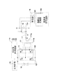
図1を参照するに、本発明に係るラインインタラクティブ無停電電源装置の第1の実施例は、電力切換器10と、低頻度トランス11と、フルブリッジ切換回路(full-bridge switching circuit)12と、主制御器13と、充放電モード制御器14と、再充電可能のバッテリー15と、高頻度充電回路16とを有する。
Referring to FIG. 1, a first embodiment of a line interactive uninterruptible power supply according to the present invention includes a
電力切換器10は、交流電力入力端子AC,INに接続されている。交流電力入力端子AC,INは、商用交流電力源に接続される。
The
電力切換器10は、交流電力が負荷(図示せず)に供給されているか否かを決定する。この実施例においては、電力切換器10の一方の端子は交流電力入力端子AC,INに接続され、他方の端子Voutは交流入力端子AC,INと負荷との間に直列に接続されている。換言すれば、電力切換器10は、交流電力入力端子AC,INと負荷とに直列接続されている。
The
低頻度トランス11は、2つのコイル、すなわち巻線11a,11bを有しており、また充電のための作動回数が少ない。一方の巻線11aは負荷に接続されていると共に、電力切換器10を介して交流電力源に接続されている。
The low-
フルブリッジ切換回路12は、2つの半ブリッジ切換回路(half-bridge switching circuit)121,122に接続されている。2つの半ブリッジ切換回路121,122に直列的に接続された2つの接続点は、低頻度トランス11の他の巻線11bに接続されている。
The full
主制御器13は、電力切換器10に接続されている。
The
充放電モード制御器14は、主制御器13とフルブリッジ切換回路12とに接続されており、また主制御器13からの充電指令又は放電指令に応じて充電モード又は放電モードに入るように、フルブリッジ切換回路12を作動させる。
The charge /
再充電可能のバッテリー15は、フルブリッジ切換回路12を介して充電又は放電をするように、フルブリッジ切換回路12に接続されている。
The
高頻度充電回路16は、交流電力を直流電流に変換してバッテリー15に頻繁に充電するように、交流電力入力端子AC,INとバッテリー15との間に接続されている。この実施例においては、高頻度充電回路16は、整流器161と高頻度充電器162とを有する。
The high-
このラインインタラクティブ無停電電源装置は、作動回数の多い高頻度充電回路16を交流電力入力端子AC,INとバッテリー15との間に付加している。交流電力源の電力が正常に供給されていると、高頻度充電回路16は、バッテリー15が満充電でないか否かを検出する。
In this line interactive uninterruptible power supply, a high-
整流器161から出力される直流電力は、バッテリー15に供給するための特定の電圧を有する直流電力に変換されて、バッテリー15に充電されかつそのバッテリー15を満充電に維持する。その結果、ラインインタラクティブ無停電電源装置は、低頻度トランス11とフルブリッジ切換回路12とを介することなく、バッテリー15に充電することができ、付加的な電力損失を効果的に回避することができる。
The direct current power output from the
図2を参照するに、本発明に従う他のラインインタラクティブ無停電電源装置は、切換器17を付加していることを除いて、図1に示すラインインタラクティブ無停電電源装置とほぼ同じ構造を有する。切換器17は、低頻度トランス11の巻線111aと電力切換器10との間に直列的に接続されており、また充放電モード制御器14によりオン又はオフに切り換えるように制御される。
Referring to FIG. 2, another line interactive uninterruptible power supply according to the present invention has substantially the same structure as the line interactive uninterruptible power supply shown in FIG. 1 except that a
図3Aを参照するに、バッテリー15の充電量が満充電であることを示す信号を主制御器13が充放電モード制御器14に出力すると、充放電モード制御器14は、低頻度トランス11を交流電力源と負荷とから切り離すように、切換器17をオフにする。この実施例において、切換器17は、リレー、メタル・オキサイド型の電界効果トランジスタ(MOSFET)、双方向サイリスタ(TRIAC)、絶縁ゲートハイポーラトランジスタ(IGBT)等の1つとすることができる。
Referring to FIG. 3A, when the
一般に、バッテリーの蓄電量は、満充電後、僅かに低下する。そのようなバッテリーの蓄電量の僅かな低下が検出されると、主制御器は充放電制御器に小電流充電モード指令を出力する。これにより充放電モード制御器は、切換器をオフに切り換えて、低頻度トランスを交流電力源及び負荷から切り離した状態に維持する。その間、高頻度充電回路は、交流電力を直流電流に直接変換して、バッテリーに充電するように、作用する。 Generally, the amount of electricity stored in a battery slightly decreases after full charge. When such a slight decrease in the charged amount of the battery is detected, the main controller outputs a small current charge mode command to the charge / discharge controller. As a result, the charge / discharge mode controller switches the switch off and maintains the low-frequency transformer in a state disconnected from the AC power source and the load. Meanwhile, the high frequency charging circuit acts to directly convert alternating current power into direct current and charge the battery.
図3Bを参照するに、無停電電力装置のバッテリー15の電力は、交流電力の停電時間が短い場合に負荷に供給するための交流電力に変換されて、低下する。このため、バッテリー15の蓄電量は大きく低下する。これにより、主制御器は、大電流充電モード指令を充放電モード制御器14に出力する。
Referring to FIG. 3B, the power of the
それにより充放電制御器14は、低頻度トランス11を交流電力源と負荷とに接続するように、切換器17をオンに維持する。その結果、交流電力源は、バッテリー15が満充電になるまで、低頻度トランス11とフルブリッジ切換回路12とを介して、バッテリー15を大直流電力で速やかに充電することに用いられる。
Thereby, the charge /
これにより、正常な交流電力の時間が異常電力供給時間又は停電時間より長いことから、本発明は、バッテリーの充電のために低変換効率の低頻度トランスを採用することにより生じる電力損失を回避するために、高頻度充電回路を付加している。またこの実施例においては、通常の交流電力が検出されたとき、低頻度トランスは、余分な電力消費を避けるために交流電力源から切り離される。上記のような回路構成において、本発明に係る無停電電源装置は、正常の交流電力に対し0.5Wを消費するにすぎず、それにより電力節約効果に達成する。 Thus, since the time of normal AC power is longer than the abnormal power supply time or power failure time, the present invention avoids power loss caused by adopting a low-frequency transformer with low conversion efficiency for charging the battery. Therefore, a high-frequency charging circuit is added. Also in this embodiment, when normal AC power is detected, the low frequency transformer is disconnected from the AC power source to avoid extra power consumption. In the circuit configuration as described above, the uninterruptible power supply according to the present invention consumes only 0.5 W with respect to normal AC power, thereby achieving a power saving effect.
本発明に関して、上記のような種々の特徴及び利点を発明の構成及び機能と共に述べたが、それらは実施例についての説明である。本発明は,特許請求の範囲の趣旨を逸脱しない限り、種々変更することができる。 Various features and advantages as described above have been described in connection with the present invention, along with the structure and function of the invention, which are illustrative of the embodiments. The present invention can be variously modified without departing from the gist of the claims.
10 電力切換器
11 低頻度トランス
12 フルブリッジ切換回路
13 主制御器
14 充放電モード制御器
15 再充電可能のバッテリー
16 高頻度充電回路
111a,111b 巻線
121,122 半ブリッジ切換回路
DESCRIPTION OF
Claims (6)
2つの巻線を有するトランスであって、一方の前記巻線が前記負荷と前記交流電力源とに接続されるトランスと、
前記トランスの他方の前記巻線に接続された直列接続点を有する2つの半ブリッジ切換回路を有するフルブリッジ切換回路と、前記電力切換器に接続された主制御器と、
前記主制御器と前記フルブリッジ切換回路とに接続された充放電モード制御器であって、前記主制御器からの充電指令又は放電指令にしたがって充電モード又は放電モードに入るように前記フルブリッジ切換回路を作動させる充放電モード制御器と、
前記トランスの前記一方の巻線と前記電力切換器との間に直列に接続されて、オン又はオフに切り換るように前記充放電モード制御器により制御される切換器と、
前記フルブリッジ切換回路に接続された、再充電可能のバッテリーであって、前記フルブリッジ切換回路を介して充放電を実行するバッテリーと、
前記交流電力入力端子と前記バッテリーとの間に接続された充電回路であって、前記交流電力源の交流電力を直流電力に変換する充電回路とを含み、
前記バッテリーが満充電状態のときに前記トランスおよび前記フルブリッジ切換回路を経由することなく前記充電回路のみを介して直接充電するために、前記充放電モード制御器が前記切換器を制御して前記電力切換器から前記トランスを切り離す一方で、前記充電回路が前記バッテリーを満充電状態に維持することを特徴とする、省電力ラインインタラクティブ無停電電源装置。 To determine whether the power of the AC power source is supplied to the load, the power switch set which is connected to the AC power input terminal connected to the AC power source,
A transformer having two windings, wherein one of the windings is connected to the load and the AC power source;
A full-bridge switching circuit having two half-bridge switching circuit having connected the series connection point to the other of the windings of the transformer, a main controller connected to said power switching device,
A charge / discharge mode controller connected to the main controller and the full bridge switching circuit, wherein the full bridge switching is performed so as to enter a charge mode or a discharge mode according to a charge command or a discharge command from the main controller. A charge / discharge mode controller for operating the circuit;
A switch connected in series between the one winding of the transformer and the power switch, and controlled by the charge / discharge mode controller to switch on or off;
A rechargeable battery connected to the full-bridge switching circuit for performing charging and discharging via the full-bridge switching circuit;
A charging circuit connected between the AC power input terminal and the battery, the charging circuit for converting AC power of the AC power source into DC power,
In order to charge directly only through the charging circuit without going through the transformer and the full-bridge switching circuit when the battery is in a fully charged state, the charge / discharge mode controller controls the switch to A power saving line interactive uninterruptible power supply , wherein the charging circuit maintains the battery in a fully charged state while disconnecting the transformer from a power switch .
Applications Claiming Priority (2)
| Application Number | Priority Date | Filing Date | Title |
|---|---|---|---|
| TW98215886U TWM373601U (en) | 2009-08-28 | 2009-08-28 | Energy-saving on-line interactive type uninterruptible power supply system |
| TW098215886 | 2009-08-28 |
Publications (2)
| Publication Number | Publication Date |
|---|---|
| JP2011050231A JP2011050231A (en) | 2011-03-10 |
| JP5486400B2 true JP5486400B2 (en) | 2014-05-07 |
Family
ID=42434328
Family Applications (1)
| Application Number | Title | Priority Date | Filing Date |
|---|---|---|---|
| JP2010114259A Active JP5486400B2 (en) | 2009-08-28 | 2010-05-18 | Power saving line interactive uninterruptible power supply |
Country Status (5)
| Country | Link |
|---|---|
| US (1) | US8314593B2 (en) |
| EP (1) | EP2290785B1 (en) |
| JP (1) | JP5486400B2 (en) |
| PL (1) | PL2290785T3 (en) |
| TW (1) | TWM373601U (en) |
Families Citing this family (13)
| Publication number | Priority date | Publication date | Assignee | Title |
|---|---|---|---|---|
| TWI387182B (en) * | 2010-03-24 | 2013-02-21 | Powercom Co Ltd | Temperature-sensing uninterruptible power supply system and method for controlling the same |
| US20130187468A1 (en) * | 2012-01-24 | 2013-07-25 | Google Inc. | Uninterruptible power supply control in distributed power architecture |
| WO2014052641A1 (en) * | 2012-09-28 | 2014-04-03 | Henry Shum | High-efficiency battery charger |
| CN103151809B (en) * | 2012-11-15 | 2016-03-02 | 苏州华德睿电子科技有限公司 | A kind of method of efficient voltage control of power-supply management system |
| US20140265945A1 (en) * | 2013-03-15 | 2014-09-18 | Infineon Technologies Austria Ag | Electric Drive System |
| WO2014209274A1 (en) * | 2013-06-25 | 2014-12-31 | Hewlett-Packard Development Company, L.P. | Uninterruptible power supply with inverter,charger, and active filter |
| WO2015076819A1 (en) * | 2013-11-22 | 2015-05-28 | Schneider Electric It Corporation | Lps architecture for ups systems |
| US9379575B2 (en) * | 2014-03-07 | 2016-06-28 | Nissan North America, Inc. | Battery charger noise reduction by frequency switching |
| US10050548B2 (en) * | 2014-09-29 | 2018-08-14 | The Boeing Company | No-break power transfer |
| CN107546836B (en) | 2016-06-23 | 2019-11-26 | 维谛技术有限公司 | A kind of ups power |
| CN110249499A (en) * | 2016-12-15 | 2019-09-17 | 万喻 | Low emissivity uninterruptible power supply |
| CN109428388A (en) | 2017-09-01 | 2019-03-05 | 硕天科技股份有限公司 | Uninterrupted power supply system |
| US11011926B2 (en) * | 2018-07-03 | 2021-05-18 | Schneider Electric It Corporation | Adaptive charger |
Family Cites Families (13)
| Publication number | Priority date | Publication date | Assignee | Title |
|---|---|---|---|---|
| US5302858A (en) * | 1991-12-11 | 1994-04-12 | Best Power Technology, Incorporated | Method and apparatus for providing battery charging in a backup power system |
| US5567996A (en) * | 1995-01-30 | 1996-10-22 | Yu; Shih-Chung | AC power supply unit |
| US5602462A (en) * | 1995-02-21 | 1997-02-11 | Best Power Technology, Incorporated | Uninterruptible power system |
| JPH1014131A (en) * | 1996-06-21 | 1998-01-16 | Hitachi Ltd | Uninterruptible power unit provided with dc output |
| JP3805844B2 (en) * | 1996-12-05 | 2006-08-09 | 株式会社アイ・ヒッツ研究所 | Uninterruptible power supply |
| JPH10228337A (en) * | 1997-02-17 | 1998-08-25 | Nippon Electric Ind Co Ltd | Computer case with uninterruptive power function |
| US6178514B1 (en) * | 1998-07-31 | 2001-01-23 | Bradley C. Wood | Method and apparatus for connecting a device to a bus carrying power and a signal |
| AU4022900A (en) * | 1999-03-22 | 2000-10-09 | Escript, Inc. | Method and apparatus for medical covering group request processing, review and management |
| JP2002064947A (en) * | 2000-08-18 | 2002-02-28 | Japan Storage Battery Co Ltd | Uninterruptible direct-current power supply |
| JP2002118983A (en) * | 2000-10-02 | 2002-04-19 | Toshiba Battery Co Ltd | Uninterruptible power supply |
| US6479970B2 (en) * | 2001-04-03 | 2002-11-12 | Anantha B. Reddy | Un-interruptible power supply |
| JP4276193B2 (en) * | 2005-03-03 | 2009-06-10 | 株式会社明電舎 | Charging method for instantaneous voltage drop compensator |
| JP2008161004A (en) * | 2006-12-26 | 2008-07-10 | Fuji Electric Systems Co Ltd | Uninterruptible power unit |
-
2009
- 2009-08-28 TW TW98215886U patent/TWM373601U/en not_active IP Right Cessation
- 2009-10-22 US US12/603,952 patent/US8314593B2/en active Active
-
2010
- 2010-05-14 PL PL10162823T patent/PL2290785T3/en unknown
- 2010-05-14 EP EP20100162823 patent/EP2290785B1/en active Active
- 2010-05-18 JP JP2010114259A patent/JP5486400B2/en active Active
Also Published As
| Publication number | Publication date |
|---|---|
| EP2290785B1 (en) | 2014-04-23 |
| US8314593B2 (en) | 2012-11-20 |
| TWM373601U (en) | 2010-02-01 |
| PL2290785T3 (en) | 2014-09-30 |
| EP2290785A2 (en) | 2011-03-02 |
| JP2011050231A (en) | 2011-03-10 |
| EP2290785A3 (en) | 2013-03-06 |
| US20110095727A1 (en) | 2011-04-28 |
Similar Documents
| Publication | Publication Date | Title |
|---|---|---|
| JP5486400B2 (en) | Power saving line interactive uninterruptible power supply | |
| JP5567684B2 (en) | Battery balancing circuit and method for balancing energy stored in a plurality of cells of a battery having a first terminal and a second terminal | |
| TW201601419A (en) | Uninterruptible power supply apparatus | |
| TWI643425B (en) | Charging power system with low standby power consumption and method of controlling the same | |
| JP2011151952A (en) | Power supply device | |
| US7982339B2 (en) | Controlling method of a battery mode of a uninterruptible power supply for an active power factor corrected load | |
| AU2015389440A1 (en) | Power supply device and air-conditioning device | |
| EP2904678A1 (en) | High-efficiency electric conversion and continuity management system for uninterruptible power supplies (ups) and derived apparatuses | |
| US20140021790A1 (en) | Method for controlling output waveforms of an uninterruptible power supply | |
| US20090179496A1 (en) | Power saving uninterruptible power supply | |
| KR101417492B1 (en) | Uninterruptible powerr supply connected to power system and control method thereof | |
| CN105634108B (en) | Off-line uninterrupted power supply | |
| JP4487210B2 (en) | Uninterruptible power system | |
| JPH04304160A (en) | Dc power supply with battery backup function | |
| TWI643427B (en) | Uninterruptable power supply system | |
| JP6076215B2 (en) | Power supply system | |
| JP2007288830A (en) | Uninterruptible power source supply device | |
| JP5069363B1 (en) | Charger | |
| WO2016031098A1 (en) | Power supply device | |
| JP2000139040A (en) | Uninterruptible power supply | |
| CN105098964A (en) | Dual-supply automatic changeover switch | |
| JP2011061949A (en) | Instantaneous voltage drop protective device | |
| CN116054373A (en) | Uninterruptible power supply and power supply switching method | |
| JP2021097561A (en) | Ac/dc power supply circuit and electrical device | |
| WO2008032457A1 (en) | Power supply circuit and power supply method |
Legal Events
| Date | Code | Title | Description |
|---|---|---|---|
| A621 | Written request for application examination |
Free format text: JAPANESE INTERMEDIATE CODE: A621 Effective date: 20110607 |
|
| A977 | Report on retrieval |
Free format text: JAPANESE INTERMEDIATE CODE: A971007 Effective date: 20121115 |
|
| A131 | Notification of reasons for refusal |
Free format text: JAPANESE INTERMEDIATE CODE: A131 Effective date: 20130402 |
|
| A601 | Written request for extension of time |
Free format text: JAPANESE INTERMEDIATE CODE: A601 Effective date: 20130625 |
|
| A602 | Written permission of extension of time |
Free format text: JAPANESE INTERMEDIATE CODE: A602 Effective date: 20130628 |
|
| RD02 | Notification of acceptance of power of attorney |
Free format text: JAPANESE INTERMEDIATE CODE: A7422 Effective date: 20130703 |
|
| A521 | Request for written amendment filed |
Free format text: JAPANESE INTERMEDIATE CODE: A523 Effective date: 20130802 |
|
| TRDD | Decision of grant or rejection written | ||
| A01 | Written decision to grant a patent or to grant a registration (utility model) |
Free format text: JAPANESE INTERMEDIATE CODE: A01 Effective date: 20140207 |
|
| A61 | First payment of annual fees (during grant procedure) |
Free format text: JAPANESE INTERMEDIATE CODE: A61 Effective date: 20140221 |
|
| R150 | Certificate of patent or registration of utility model |
Ref document number: 5486400 Country of ref document: JP Free format text: JAPANESE INTERMEDIATE CODE: R150 |
|
| R250 | Receipt of annual fees |
Free format text: JAPANESE INTERMEDIATE CODE: R250 |
|
| R250 | Receipt of annual fees |
Free format text: JAPANESE INTERMEDIATE CODE: R250 |
|
| R250 | Receipt of annual fees |
Free format text: JAPANESE INTERMEDIATE CODE: R250 |
|
| R250 | Receipt of annual fees |
Free format text: JAPANESE INTERMEDIATE CODE: R250 |
|
| R250 | Receipt of annual fees |
Free format text: JAPANESE INTERMEDIATE CODE: R250 |
|
| R250 | Receipt of annual fees |
Free format text: JAPANESE INTERMEDIATE CODE: R250 |
|
| R250 | Receipt of annual fees |
Free format text: JAPANESE INTERMEDIATE CODE: R250 |
|
| R250 | Receipt of annual fees |
Free format text: JAPANESE INTERMEDIATE CODE: R250 |