JP5484637B2 - Transmitting apparatus, receiving apparatus, and communication method - Google Patents
Transmitting apparatus, receiving apparatus, and communication method Download PDFInfo
- Publication number
- JP5484637B2 JP5484637B2 JP2013521484A JP2013521484A JP5484637B2 JP 5484637 B2 JP5484637 B2 JP 5484637B2 JP 2013521484 A JP2013521484 A JP 2013521484A JP 2013521484 A JP2013521484 A JP 2013521484A JP 5484637 B2 JP5484637 B2 JP 5484637B2
- Authority
- JP
- Japan
- Prior art keywords
- control
- signal
- unit
- processing
- transmission
- Prior art date
- Legal status (The legal status is an assumption and is not a legal conclusion. Google has not performed a legal analysis and makes no representation as to the accuracy of the status listed.)
- Active
Links
- 238000000034 method Methods 0.000 title claims description 102
- 238000004891 communication Methods 0.000 title claims description 10
- 238000012545 processing Methods 0.000 claims description 238
- 230000005540 biological transmission Effects 0.000 claims description 224
- 230000007274 generation of a signal involved in cell-cell signaling Effects 0.000 claims description 88
- 125000004122 cyclic group Chemical group 0.000 claims description 38
- 230000015572 biosynthetic process Effects 0.000 claims description 20
- 238000005259 measurement Methods 0.000 claims description 20
- 238000003786 synthesis reaction Methods 0.000 claims description 20
- 238000003780 insertion Methods 0.000 claims description 16
- 230000037431 insertion Effects 0.000 claims description 16
- 238000009826 distribution Methods 0.000 claims description 9
- 238000003860 storage Methods 0.000 claims description 5
- 230000009466 transformation Effects 0.000 claims 1
- 238000010586 diagram Methods 0.000 description 51
- 238000004364 calculation method Methods 0.000 description 29
- 230000006870 function Effects 0.000 description 12
- 238000013461 design Methods 0.000 description 8
- 230000000694 effects Effects 0.000 description 6
- 239000002131 composite material Substances 0.000 description 4
- 238000005562 fading Methods 0.000 description 4
- 230000001629 suppression Effects 0.000 description 3
- 238000006243 chemical reaction Methods 0.000 description 1
- 238000012937 correction Methods 0.000 description 1
- 238000005516 engineering process Methods 0.000 description 1
- 238000004519 manufacturing process Methods 0.000 description 1
- 239000000203 mixture Substances 0.000 description 1
- 230000010363 phase shift Effects 0.000 description 1
- 238000012805 post-processing Methods 0.000 description 1
- 230000002194 synthesizing effect Effects 0.000 description 1
Images


Classifications
-
- H—ELECTRICITY
- H04—ELECTRIC COMMUNICATION TECHNIQUE
- H04J—MULTIPLEX COMMUNICATION
- H04J11/00—Orthogonal multiplex systems, e.g. using WALSH codes
- H04J11/0023—Interference mitigation or co-ordination
- H04J11/0063—Interference mitigation or co-ordination of multipath interference, e.g. Rake receivers
-
- H—ELECTRICITY
- H04—ELECTRIC COMMUNICATION TECHNIQUE
- H04L—TRANSMISSION OF DIGITAL INFORMATION, e.g. TELEGRAPHIC COMMUNICATION
- H04L27/00—Modulated-carrier systems
- H04L27/26—Systems using multi-frequency codes
- H04L27/2601—Multicarrier modulation systems
- H04L27/2614—Peak power aspects
- H04L27/2621—Reduction thereof using phase offsets between subcarriers
-
- H—ELECTRICITY
- H04—ELECTRIC COMMUNICATION TECHNIQUE
- H04L—TRANSMISSION OF DIGITAL INFORMATION, e.g. TELEGRAPHIC COMMUNICATION
- H04L27/00—Modulated-carrier systems
- H04L27/26—Systems using multi-frequency codes
- H04L27/2601—Multicarrier modulation systems
- H04L27/2626—Arrangements specific to the transmitter only
- H04L27/2627—Modulators
- H04L27/2634—Inverse fast Fourier transform [IFFT] or inverse discrete Fourier transform [IDFT] modulators in combination with other circuits for modulation
- H04L27/2636—Inverse fast Fourier transform [IFFT] or inverse discrete Fourier transform [IDFT] modulators in combination with other circuits for modulation with FFT or DFT modulators, e.g. standard single-carrier frequency-division multiple access [SC-FDMA] transmitter or DFT spread orthogonal frequency division multiplexing [DFT-SOFDM]
Landscapes
- Engineering & Computer Science (AREA)
- Computer Networks & Wireless Communication (AREA)
- Signal Processing (AREA)
- Physics & Mathematics (AREA)
- Discrete Mathematics (AREA)
- General Physics & Mathematics (AREA)
- Mathematical Physics (AREA)
- Mobile Radio Communication Systems (AREA)
- Digital Transmission Methods That Use Modulated Carrier Waves (AREA)
- Transmitters (AREA)
Description
本発明は、送信装置、受信装置、通信システムおよび通信方法に関する。 The present invention relates to a transmission device, a reception device, a communication system, and a communication method.
デジタル通信システムにおいて、送信信号が建物などに反射して起こるマルチパスフェージングや端末の移動によって起こるドップラ変動によって、伝送路の周波数選択性と時間変動が発生する。このようなマルチパス環境において、受信信号は送信シンボルと遅延時間が経って届くシンボルと干渉した信号となる。 In a digital communication system, transmission path frequency selectivity and time variation occur due to multipath fading caused by reflection of a transmission signal on a building or the like and Doppler fluctuation caused by movement of a terminal. In such a multipath environment, the received signal is a signal that interferes with a transmitted symbol and a symbol that arrives after a delay time.
このような周波数選択性のある伝送路において、最良の受信特性を得るためシングルキャリア伝送方式が近年注目を集めている(例えば、下記非特許文献1参照)。シングルキャリア(Single Carrier:SC)伝送方式は、マルチキャリア(Multiple Carrier:MC)伝送であるOFDM(Orthogonal Frequency Division Multiplexing)伝送方式(例えば、下記非特許文献2参照)に比べピーク電力を低くすることができる。
In such a frequency selective transmission line, a single carrier transmission method has recently attracted attention in order to obtain the best reception characteristics (for example, see Non-Patent
SC伝送を行う送信機では、例えば次のような伝送を行うことによりマルチフェージング対策を行っている。まず、”Modulator”においてデジタル変調信号であるPSK(Phase Shift Keying)信号やQAM(Quadrature Amplitude Modulation)信号を生成後、プリコーダおよびIDFT(Inverse Discrete Fourier Transform)処理部によりデジタル変調信号を時間領域信号に変換する。その後マルチパスフェージング対策として、CP(Cyclic Prefix)挿入部においてCPが挿入される。CP挿入部では時間領域信号の後ろの所定数のサンプルをコピーして、送信信号の初めに付加する。この他に、マルチパスフェージング対策手段として、データのはじめ又はおわりの部分にゼロを挿入するZP(zero padding:ゼロ挿入)が行われる。 In a transmitter that performs SC transmission, for example, multifading countermeasures are taken by performing the following transmission. First, after generating a PSK (Phase Shift Keying) signal and a QAM (Quadrature Amplitude Modulation) signal as digital modulation signals in the “Modulator”, the digital modulation signal is converted into a time domain signal by a precoder and an IDFT (Inverse Discrete Fourier Transform) processing unit. Convert. Thereafter, as a countermeasure against multipath fading, a CP is inserted at a CP (Cyclic Prefix) insertion unit. The CP insertion unit copies a predetermined number of samples after the time domain signal and adds them to the beginning of the transmission signal. In addition, ZP (zero padding) for inserting zero at the beginning or end of data is performed as a multipath fading countermeasure.
また、送信ピーク電力を抑圧するため、SC伝送を行う送信機では、プリコーダでは一般的にDFT(Discrete Fourier Transform)処理が行われる。 In order to suppress transmission peak power, a transmitter that performs SC transmission generally performs DFT (Discrete Fourier Transform) processing in a precoder.
上記従来のSC伝送の技術によれば、マルチパスフェージングの影響を低減しつつ送信ピーク電力を抑圧している。しかしながら、電力効率の向上等の観点からピーク電力はより低減することが望ましい。 According to the conventional SC transmission technology, the transmission peak power is suppressed while reducing the influence of multipath fading. However, it is desirable to further reduce the peak power from the viewpoint of improving the power efficiency.
本発明は、上記に鑑みてなされたものであって、送信電力を抑圧することができる送信装置、受信装置、通信システムおよび通信方法を得ることを目的とする。 The present invention has been made in view of the above, and an object thereof is to obtain a transmission device, a reception device, a communication system, and a communication method capable of suppressing transmission power.
上述した課題を解決し、目的を達成するために、本発明は、1ブロックのデータを、Mを2以上としてM個の分割データに分割するデータ分割部と、前記M個の分割データごとにフーリエ変換処理を行い、M個のフーリエ変換後データを生成するM個のフーリエ変換部と、前記M個のフーリエ変換後データのそれぞれに対して所定の制御処理を行いM個の制御処理後データを生成するM個の制御処理部と、前記M個の制御処理後データに対して逆フーリエ変換処理を行い1つの信号への合成を行う合成処理部と、前記合成された信号に対して所定の送信処理を行い送信信号とする送信処理部と、前記M個の制御処理部で実施される制御処理に用いられるM個の制御値を1組とする制御値候補を所定数保持し、前記送信信号の電力情報に基づいて前記制御値候補のうちの1つを選択候補として選択する候補選択部と、前記選択候補に含まれるM個の制御値をそれぞれ対応する前記制御処理部へ設定するためのM個の制御信号を生成し、前記制御信号をそれぞれ対応する前記制御処理部へ入力する制御信号生成部と、を備えることを特徴とする。 In order to solve the above-described problems and achieve the object, the present invention provides a data dividing unit that divides one block of data into M divided data with M being 2 or more, and for each of the M divided data. performs Fourier transform processing, the M Fourier transform unit for generating the M Fourier transform data and, the M trailing had the M control process a predetermined control processing for each data after Fourier transform and M control processing unit for generating data, and a synthesis processor for synthesizing the one signal performs inverse Fourier transform processing on the M control post-processing data, before Kigo made signal predetermined number and transmission processing unit, a control value candidate to the M control processing set the M control values used in the practice are Ru control processing in unit of a transmission signal performs predetermined transmission processing for Based on the power information of the transmitted signal A candidate selection unit that selects one of the control value candidates as a selection candidate, and M control signals for setting the M control values included in the selection candidate to the corresponding control processing unit. And a control signal generation unit that generates and inputs the control signal to the corresponding control processing unit.
本発明によれば、送信電力を抑圧することができるという効果を奏する。 According to the present invention, there is an effect that transmission power can be suppressed.
以下に、本発明にかかる送信装置、受信装置、通信システムおよび通信方法の実施の形態を図面に基づいて詳細に説明する。なお、この実施の形態によりこの発明が限定されるものではない。 Hereinafter, embodiments of a transmission device, a reception device, a communication system, and a communication method according to the present invention will be described in detail with reference to the drawings. Note that the present invention is not limited to the embodiments.
実施の形態1.
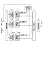
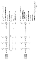
図1は、本発明にかかる送信装置の実施の形態1の機能構成例を示す図である。図1に示すように、本実施の形態の送信装置は、グループ処理部1と、信号処理部2−1〜2−M(Mは2以上の整数)と、制御処理部3−1〜3−Mと、合成処理部4と、送信処理部5と、送信アンテナ6と、電力測定部7と、制御信号生成部8と、を備える。
FIG. 1 is a diagram illustrating a functional configuration example of a first embodiment of a transmission device according to the present invention. As illustrated in FIG. 1, the transmission apparatus according to the present embodiment includes a
グループ処理部1には、入力信号として送信信号が入力される。入力信号は、例えば、PSKやQAMなどの方式で変調されたデジタル変調信号である。また、入力信号は誤り訂正符号が付加された信号でも良い。グループ処理部1は、入力信号の1ブロックをM個に分割し、分割したデータをそれぞれ信号処理部2−1〜2−Mへ入力する。なお、ここでは、グループ処理部1がM個に分割するようにしたが、グループ処理部1はM個未満の数に1ブロックのデータを分割してもよい。また、グループ処理部1は、1ブロックを分割する際、各分割データのデータ量を全て等しくなるように分割してもよいし、分割データごとにデータ量が異なるように分割してもよい。
A transmission signal is input to the
また、1ブロックは、何シンボルで構成されていてもよいが、例えば、従来の送信装置で1回の送信で送信していたデータ量とする。例えば、従来のSC伝送を行う送信装置では、送信信号を所定数のシンボル単位でDFT処理を行って周波数上の配置を行い、その後IDFT処理により時間領域信号に変換して送信する。本実施の形態では、例えば、この所定数のシンボルを1ブロックとする。 One block may be composed of any number of symbols. For example, it is assumed that the amount of data transmitted by one transmission by a conventional transmission apparatus is used. For example, in a conventional transmission apparatus that performs SC transmission, a transmission signal is subjected to DFT processing in units of a predetermined number of symbols, arranged in frequency, and then converted into a time domain signal by IDFT processing and transmitted. In the present embodiment, for example, this predetermined number of symbols is set as one block.
信号処理部2−1〜2−Mは、入力された分割データに対して、それぞれ所定の信号処理を実施し、処理後の分割データをそれぞれ制御処理部3−1〜3−Mへ入力する。所定の信号処理としては、例えば、DFT処理等が実施される。 The signal processing units 2-1 to 2-M perform predetermined signal processing on the input divided data, and input the processed divided data to the control processing units 3-1 to 3-M, respectively. . As the predetermined signal processing, for example, DFT processing or the like is performed.
制御処理部3−1〜3−Mは、入力されたデータに対して、制御信号生成部8からの制御信号に基づいて、所定の制御処理を実施する。所定の制御処理は、送信電力を抑制するための処理であり、例えば、位相回転、タイミングシフト、循環シフトや電力配分等であり、これらの組み合わせであってもよい。合成処理部4は、制御処理部3−1〜3−Mによって所定の制御処理が施された後の分割データを所定の合成処理により1つの合成信号に合成し、送信処理部5へ入力する。所定の合成処理は、例えば、IDFT処理であり、CP挿入処理やZP処理等を含んでいてもよい。
The control processing units 3-1 to 3 -M perform predetermined control processing on the input data based on the control signal from the control
送信処理部5は、合成処理部4により合成された合成信号に対して無線信号として送信するための所定の送信処理を実施して送信信号とし、送信信号を送信アンテナ6から送出する。
The
電力測定部7は、送信処理部5から出力される送信信号の電力を測定し、所定の電力情報を取得する。所定の電力情報は、本実施の形態の送信装置に対する要求が規定されている(設計値等として定められている)情報を用いればよく、例えば、送信ピーク電力、送信平均電力、PAPR(Peak to Average Power ratio)等を用いることができる。
The
制御信号生成部8は、電力測定部7が取得した電力情報に基づいて、電力情報が目標値を満たすよう制御処理部3−1〜3−Mを制御する制御信号を生成して、生成した制御信号を制御処理部3−1〜3−Mへ入力する。目標値は、例えば送信電力に関する設計目標等である。例えば、電力測定部7が電力情報として送信ピーク電力を取得し、制御信号生成部8は、送信ピーク電力が所定の目標値(設計目標等)以下となるよう制御信号を生成する。なお、一般的な設計目標は送信ピーク電力を最小にすることであるが、設計目標はこれに限定されない。
The control
なお、ここでは、説明の簡易化のため送信アンテナの数を1本とした例について説明するが、本実施の形態の動作は、数本の送信アンテナを用いたシステムに適用することも可能である。この場合、数本の送信アンテナが、同一の送信信号を送信してもよいし、異なる送信信号を送信してもよい。異なる送信信号を送信する場合は、例えば、合成処理部4、送信処理部を複数備え、送信アンテナごとに合成処理部4が合成信号を生成すればよい。この場合、例えば、電力測定部7は送信処理部ごとに電力情報を取得し、制御信号生成部8は、同一の送信アンテナに接続される制御処理部3−1〜3−Mごとに、電力情報が設計目標を満たすように制御信号を生成する。
Note that, here, an example in which the number of transmission antennas is one will be described for the sake of simplification. However, the operation of this embodiment can also be applied to a system using several transmission antennas. is there. In this case, several transmission antennas may transmit the same transmission signal or different transmission signals. When transmitting different transmission signals, for example, a plurality of
次に、制御信号生成部8における制御信号の生成処理について説明する。なお、以下の説明では、具体的な一例として電力情報を送信ピーク電力とし、設計目標を送信ピーク電力が所定の目標値以下とすることとする場合について説明する。制御信号生成部8は、制御処理部3−1〜3−Mに設定するための制御値のセットを複数セットあらかじめ保持しておく。制御値の1セットは、制御処理部3−1〜3−Mにそれぞれ対応する制御値が含まれているとする。制御処理部3−1〜3−Mが実施する制御処理として、位相回転を行う場合には、制御信号生成部8は、制御処理部3−1〜3−Mが各々回転させる位相回転量を制御値のセットとして保持する。制御処理部3−1〜3−Mは、初期状態(制御信号を受信しない状態)では、信号処理部2−1〜2−Mからの入力信号をそのまま出力するよう設定されていてもよいし、初期状態で上述の制御値のセットのいずれか1セットに対応する制御値がそれぞれ設定されていてもよい。
Next, control signal generation processing in the control
制御信号生成部8は、保持している制御値のセットのうちあるセットに対応する制御信号を生成して、それぞれ対応する制御処理部3−1〜3−Mへ入力し、その制御値のセットに対応する電力情報を電力測定部7から取得する。同様に、全てのセットについて対応する送信ピーク電力を取得し、送信ピーク電力が所定の目標値以下でかつ最適な制御値のセットを選択する。最適な制御値のセットの選択方法は、電力情報が何であるか、設計目標がどのようなものであるかに依存するが、電力情報が送信ピーク電力である場合には、例えば、送信ピーク電力が低いものを最適な制御値のセットとして選択することができる。最適な制御値のセットの選択後、制御信号生成部8は、選択した制御値のセットに対応する制御信号を生成して、それぞれ対応する制御処理部3−1〜3−Mへ入力する。このように、本実施の形態では、制御信号生成部8は、制御信号を生成する制御信号生成部としての機能とともに制御値の候補を選択する候補選択部としての機能を有する。
The control
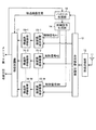
次に、本実施の形態の送信装置によって送信された信号を受信する受信装置について説明する。図2は、本実施の形態の受信装置の機能構成例を示す図である。図2に示すように、本実施の形態の受信装置は、受信アンテナ11と、受信処理部12と、合成解除・分割部(分割部)13と、制御信号生成部14と、制御処理解除部15−1〜15−Mと、受信信号処理部16−1〜16−Mと、復調処理部17と、を備える。
Next, a receiving apparatus that receives a signal transmitted by the transmitting apparatus of the present embodiment will be described. FIG. 2 is a diagram illustrating a functional configuration example of the receiving apparatus according to the present embodiment. As shown in FIG. 2, the receiving apparatus according to the present embodiment includes a receiving
本実施の形態の送信装置によって送信された送信信号は、受信装置の受信アンテナ11により受信され、受信処理部12に入力される。受信処理部12は、受信した信号に対して所定の受信処理を実施して合成解除・分割部13へ入力する。合成解除・分割部13は、送信装置の合成処理と逆の処理を実施し、受信した信号を分解して制御処理解除部15−1〜15−Mへそれぞれ入力する。
The transmission signal transmitted by the transmission apparatus according to the present embodiment is received by the
制御信号生成部14は、送信装置が保持している制御値のセットごとに、制御を解除するための制御値(以下、解除制御値という)のセットを保持している。制御信号生成部14は、保持している解除制御値のうちのあるセットに対応する制御信号を生成して制御処理解除部15−1〜15−Mに入力する。制御処理解除部15−1〜15−Mは、入力された制御信号に基づいて送信装置の制御処理部3−1〜3−Mが実施した処理を逆の処理(制御処理解除)を実施する。例えば、制御処理が位相回転の場合は、送信装置が回転させた位相回転量と絶対値が同じで符号が逆となる位相分回転される。
The control
受信信号処理部16−1〜16−Mは、制御処理解除部15−1〜15−Mによりそれぞれ制御処理解除が施された信号に対して送信装置の信号処理部2−1〜2−Mが実施した処理と逆の処理を実施し、復調処理部17へ入力する。復調処理部17は、信号処理部2−1〜2−Mから入力された信号に対して送信側で実施された変調や符号化処理に対応した復調処理を実施し、復調処理により得られた復調誤差(メトリック値)を制御信号生成部14へ入力する。
The reception signal processing units 16-1 to 16-M respectively transmit the signal processing units 2-1 to 2-M of the transmission apparatus to the signals for which the control processing cancellation is performed by the control processing cancellation units 15-1 to 15-M. The process reverse to the process performed by is performed and input to the
制御信号生成部14は、復調処理部17から入力されたメトリック(メトリック値)を解除制御値のセットと対応づけて保持し、以降同様に、保持している全ての解除制御値のセットに対応するメトリックを取得する。そして、制御信号生成部14は、メトリックの低い解除制御値のセットを最適なセットとして選択し、選択した解除制御値のセットに対応する制御信号を生成して制御処理解除部15−1〜15−Mへそれぞれ入力する。以降は、選択された解除制御値のセットに対応する制御信号に基づいて制御処理解除が実施される。
The control
また、本実施の形態の送信装置がパイロット信号を送信する場合に、本実施の形態の動作を適用してもよい。図3は、パイロット信号を送信する場合の送信装置の機能構成例を示す図である。図3に示すように、この送信装置の構成は、パイロットシンボル生成部9と制御処理部3−(M+1)を追加する以外は、図1の構成と同様である。図3の構成例では、パイロットシンボル生成部9は所定のパイロットシンボルを生成し、制御処理部3−(M+1)がパイロットシンボルに対して所定の制御処理を行う。合成処理部4は、分割データとともにパイロット信号を合成して合成信号を生成する。また、制御信号生成部8は、制御処理部3−1〜3−(M+1)に対応する制御値のセットを保持し、制御処理部3−1〜3−(M+1)に対する制御信号を生成する。これ以外の動作は、図1の例と同様である。
Moreover, when the transmission apparatus of this Embodiment transmits a pilot signal, you may apply the operation | movement of this Embodiment. FIG. 3 is a diagram illustrating a functional configuration example of a transmission apparatus when transmitting a pilot signal. As shown in FIG. 3, the configuration of this transmission apparatus is the same as the configuration of FIG. 1 except that a pilot
また、図4は、図3に示した送信装置が送信した送信信号を受信する受信装置の構成例である。図4に示す受信装置は、パイロット処理部18を追加する以外は図2に示した受信装置と同様である。図4に示した受信装置では、合成解除・分割部13が、受信信号の分解の際に、分解したパイロットシンボルをパイロット処理部18へ入力し、パイロット処理部18がパイロットシンボルを用いて伝送路推定等の処理を実施し、処理結果を復調処理部17へ入力する。復調処理部17は、この復調の際にこの伝送路推定値を用いて復調処理を行う。これ以外の動作は、図2の例と同様である。
FIG. 4 is a configuration example of a receiving apparatus that receives a transmission signal transmitted by the transmitting apparatus illustrated in FIG. The receiving apparatus shown in FIG. 4 is the same as the receiving apparatus shown in FIG. 2 except that a
図3の構成例では、パイロットシンボル生成部9が、既知信号であるパイロットシンボルを生成し、合成処理部4が、データとパイロットシンボルとを合成する。これにより、パイロットシンボルを1ブロックのデータの間に挿入することができる。従来の1ブロックのデータを分割しないで送信するSC伝送では、例えば所定数のブロックのデータごとにパイロットシンボルが送信される等パイロットシンボルの配置に制約があった。これに対し、本実施の形態では、実施の形態1と同様に1ブロックのデータを分割し、分割したデータの間にパイロットシンボルを配置することができるため、パイロットシンボルの配置の自由度が高まる。
In the configuration example of FIG. 3, the pilot
このようにパイロットシンボルをデータと合成して送信する場合、データのみで送信する場合に比べ、ピーク電力が高くなる。本実施の形態では、実施の形態1と同様に、電力情報に基づいて適切な制御値のセットを選択して所定の制御処理を行うため、パイロットシンボルをデータと合成して送信する場合にもピーク電力を抑えることができる。 In this way, when pilot symbols are combined with data and transmitted, the peak power is higher than when transmitting only data. In the present embodiment, as in the first embodiment, an appropriate set of control values is selected on the basis of power information and a predetermined control process is performed. Therefore, even when pilot symbols are combined with data and transmitted. Peak power can be suppressed.
パイロットシンボルとしてはどのようなものを用いてもよいが、例えば「S. Beyme and C. Leung,“Efficient computation of DFT of Zadoff−Chu sequences”,Electronics Letters,vol.45,no.9,Apr.2009,pp.461−463」で紹介されているようなZadoff Chu系列などのピーク電力を抑制する系列を用いることができる。 Any pilot symbol may be used, for example, “S. Beyme and C. Leung,“ Efficient computation of DFT of Zadoff-Chu sequences ”, Electronics Letters, vol. 45, no. 9, Apr. 2009, pp. 461-463 ”, such as a Zadoff Chu sequence, a sequence that suppresses peak power can be used.
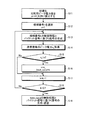
次に、本実施の形態の制御信号生成部14について詳細に説明する。本実施の形態では、図2の構成例の場合も図4の構成例の場合も制御信号生成部14の動作は同様である。図5は、本実施の形態の制御信号生成部14が実施する解除制御値のセット(制御値の候補)の選択手順の一例を示す図である。なお、ここでは、保持している全ての解除制御値のセットの数をC個とし、候補#1〜候補#CのC個の候補から最適な候補を選択するとして説明する。図5に示すように、制御信号生成部14は、初期化として比較用メトリック値xを無限大(できるだけ大きな値)に設定する(ステップS1)。次に、制御信号生成部14は、C個の候補から候補#1を選択し、選択した候補番号kを1とする(ステップS2)。
Next, the control
候補#kの解除制御値に対応する制御信号を生成して、制御処理解除部15−1〜15−Mへ入力し復調処理を実施する(ステップS3)。制御信号生成部14は、候補#kに対する復調結果のメトリック値xkを復調処理部17から取得し(ステップS4)、xkがxより小さいか否かを判断する(ステップS5)。xkがxより小さい場合(ステップS5 Yes)、x=xkとし、best_cand(最適候補の番号)=kとする(ステップS6)。その後、制御信号生成部14は、k=k+1として候補#(k+1)を選択し(ステップS7)、kがCより大きいか否かを判断する(ステップS8)。kがCより大きい場合(ステップS8 Yes)、best_candに対応する復調結果を出力結果とする復調結果に指示する(ステップS9)。A control signal corresponding to the cancellation control value of candidate #k is generated and input to the control processing cancellation units 15-1 to 15-M to perform demodulation processing (step S3). The control
ステップS5でxkがx以上であった場合(ステップS5 No)、ステップS7へ進む。ステップS8でkがC以下の場合(ステップS8 No)、ステップS3へ戻る。If x k is greater than or equal to x in step S5 (No in step S5), the process proceeds to step S7. If k is equal to or less than C in step S8 (No in step S8), the process returns to step S3.
なお、ここでは、受信装置が、送信装置においてどの制御値のセットが選択されたかを知らないことを前提として説明したが、送信装置が、なんらかの手段でどの制御値のセットを選択したかを受信装置に通知するようにしてもよい。その場合は、受信装置の制御信号生成部14は、全ての解除制御値のセットについてメトリックを取得する処理を実施する必要はなく、通知に基づいて解除制御値のセットを選択すればよい。
Here, the description has been made on the assumption that the receiving device does not know which control value set is selected in the transmitting device, but the transmitting device receives which control value set is selected by some means. You may make it notify to an apparatus. In that case, the control
以上のように、本実施の形態では、送信するデータを複数の分割データに分割し、制御処理部3−1〜3−Mが分割データごとに所定の制御処理を行い、合成処理部4が制御処理後の信号を合成し、送信処理部5が合成後信号を送信するようにした。そして、電力測定部7が、送信処理部5が生成した送信信号の電力に基づいて電力情報を取得し、制御信号生成部14が、複数の制御値のセットを保持し、電力情報に基づいて、保持しているセットのうちのひとつを選択して選択した制御値に基づいて制御信号を生成し、制御処理部3−1〜3−Mへ入力するようにした。このため、送信電力を抑圧することができる。
As described above, in the present embodiment, the data to be transmitted is divided into a plurality of divided data, the control processing units 3-1 to 3-M perform predetermined control processing for each divided data, and the
実施の形態2.
図6は、本発明にかかる送信装置の実施の形態2の機能構成例を示す図である。図6に示すように、本実施の形態の送信装置の構成は、パイロットシンボル生成部9の代わりにパイロットシンボル生成部9aを備える以外は、実施の形態1の図3の例と同様である。実施の形態1と同様の機能を有する構成要素は、実施の形態1と同一の符号を付して重複する説明を省略する。
FIG. 6 is a diagram illustrating an example of a functional configuration of the transmitting apparatus according to the second embodiment of the present invention. As shown in FIG. 6, the configuration of the transmission apparatus of the present embodiment is the same as that of FIG. 3 of
本実施の形態では、以下のように、パイロットシンボルを選択した制御値のセット(候補)によって異なる値にする。このようにすると、受信側でパイロットシンボルに基づいて送信側で選択した候補を知ることができ、受信側の処理を削減することができる。 In the present embodiment, the pilot symbols are set to different values depending on the selected control value set (candidate) as follows. In this way, the reception side can know the candidate selected on the transmission side based on the pilot symbol, and the processing on the reception side can be reduced.
なお、図6では、パイロットシンボル生成部9aの出力に対しては、制御処理が施されない例を示しているが、制御処理の内容によっては、パイロットシンボル生成部9aの出力に対しても制御処理を施すようにしてもよい。例えば、受信側において、パイロットシンボルに制御処理が施されていても、パイロット系列の特定への影響が少ない制御処理(例えば、電力制御等)については、パイロットシンボル生成部9aの出力に対しても制御処理を施すようにしてもよい。
FIG. 6 shows an example in which the control process is not performed on the output of the pilot
図7は、本実施の形態の制御信号生成部8の処理手順の一例を示す図である。図8は、本実施の形態の制御信号生成部8およびパイロットシンボル生成部9aの構成例を示す図である。図7および図8を用いてパイロットシンボルを選択した制御値のセット(候補)によって異なる値とする場合の動作例について説明する。
FIG. 7 is a diagram illustrating an example of a processing procedure of the control
図8に示すように、本実施の形態の制御信号生成部8は、選択部81と、選択回路82と、メモリ83と、を備える。メモリ83には、実施の形態1で説明した制御値の候補(セット)がC個(制御値候補#1〜制御値候補#C)格納されている。本実施の形態のパイロットシンボル生成部9aは、選択回路91と、メモリ92と、を備える。メモリ92は、パイロット系列#1〜パイロット系列#Cが格納されている。パイロット系列#1〜パイロット系列#Cは、互いに異なる系列とする。ここでは“系列”は一定の順序に従い並べられた複素数又は実数とするが、これに限らずどのような系列を用いても良い。
As shown in FIG. 8, the control
図7に示すように、制御信号生成部8では、選択部81が、初期化として比較用ピーク電力xを無限大(できるだけ大きな値)に設定する(ステップS11)。次に、選択部81は、メモリ83に格納されているC個の制御値候補から制御値候補#1を選択し、選択した候補番号kを1とする(ステップS12)。
As shown in FIG. 7, in the control
選択部81は、制御値候補#kに対応する制御信号を生成して、制御処理部3−1〜3−Mへ入力し、またパイロットシンボル生成部9aに候補番号(k)を選択したことを通知する選択信号を入力し、パイロットシンボル生成部9aは選択信号に基づいて候補番号(k)に対応するシンボル系列を選択してパイロットシンボルとして合成処理部4へ入力する(ステップS13)。これにより、候補番号kに対応する制御値とパイロット系列を用いた合成信号が生成され、送信処理部5へ入力される。
The
選択部81は、電力測定部7から電力情報xkを取得し(ステップS14)、xkがxより小さいか否かを判断する(ステップS15)。xkがxより小さい場合(ステップS15 Yes)、x=xkとし、best_cand(最適候補の番号)=kとする(ステップS16)。その後、制御信号生成部8は、候補番号をk=k+1とし(ステップS17)、kがCより大きいか否かを判断する(ステップS18)。kがCより大きい場合(ステップS18 Yes)、best_candに対応する制御値のセットに基づいて制御信号を生成して制御処理部3−1〜3−Mへ入力するとともに候補番号best_candを選択する選択信号をパイロットシンボル生成部9へ入力する(ステップS19)。The
ステップS15でxkがx以上であった場合(ステップS15 No)、ステップS17へ進む。ステップS18でkがC以下の場合(ステップS18 No)、ステップS13へ戻る。If x k is greater than or equal to x in step S15 (No in step S15), the process proceeds to step S17. If k is equal to or less than C in step S18 (No in step S18), the process returns to step S13.
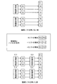
明確化のために、制御処理部3−1〜3−Mが制御処理として循環シフトを用いる例について説明する。図9は、循環シフトを用いる例を示す図である。ここでは、グループ処理部1が1ブロックのデータを2つの分割データ(2つのグループ)に分けるとし、1系列あたりのパイロットシンボル数は2とし、制御値のセット数(候補数)Cを3とする。また、各信号処理部2−1〜2−Mは、各々3つの信号を出力する(各分割データがそれぞれ3つの信号で構成される)とする。
For the sake of clarity, an example in which the control processing units 3-1 to 3-M use a cyclic shift as a control process will be described. FIG. 9 is a diagram illustrating an example using a cyclic shift. Here, it is assumed that the
図9に示すように、信号生成部2−1は、信号S0,S1,S2を出力し、信号生成部2−2は、信号T0,T1,T2を出力するとする。また、制御値候補#1,#2,#3をそれぞれ0シフト,+1シフト,+2シフトとし、0シフトの場合に対応するパイロット系列をP01,P02とし、+1シフトの場合に対応するパイロット系列をP11,P12とし、+2シフトの場合に対応するパイロット系列をP21,P22とする。また、+1シフトの場合は、制御処理部3−1,3−2に対して制御値としてそれぞれシフト無し、+1シフトを設定し、+2シフトの場合は、制御処理部3−1,3−2に対して制御値としてそれぞれシフト無し、+1シフトを設定するとする。
As shown in FIG. 9, it is assumed that the signal generation unit 2-1 outputs signals S0, S1, and S2, and the signal generation unit 2-2 outputs signals T0, T1, and T2. Further, control
この場合、図9の上段に示した循環シフトを用いない場合は、合成処理部4において信号生成部2−1,2−2が出力した順番で合成される。図9の下段に示したように循環シフトを用いて+1シフトが選択された場合は、信号生成部2−2が出力した信号は、制御処理部3−2により+1シフトされて合成処理部4へ出力される。この場合、パイロットシンボルとして、パイロット系列P11,P12が生成され、合成処理部4へ入力される。
In this case, when the cyclic shift shown in the upper part of FIG. 9 is not used, the
次に、本実施の形態の受信装置について説明する。図10は、本実施の形態の受信装置の機能構成例を示す図である。図10に示すように、本実施の形態の受信装置は、制御信号生成部14,パイロット処理部18の代わりに制御信号生成部14a,パイロット処理部18aを備える以外は、実施の形態1の図4の例と同様である。
Next, the receiving apparatus of this Embodiment is demonstrated. FIG. 10 is a diagram illustrating a functional configuration example of the receiving apparatus according to the present embodiment. As shown in FIG. 10, the receiving apparatus of the present embodiment is the same as that of
本実施の形態の受信装置では、合成解除・分割部13が、受信信号の分解の際に、分解したパイロットシンボルをパイロット処理部18aへ入力し、パイロット処理部18aが、パイロットシンボルを用いて伝送路推定等の処理を実施し、処理結果を復調処理部17へ入力する。さらに、本実施の形態のパイロット処理部18aは、送信装置が保持する制御値候補ごとのパイロット系列を保持しており、保持しているパイロット系列と受信信号に含まれるパイロット系列を比較する(例えば相関処理等)ことにより、どのパイロット系列が送信されたかを判定してその結果(候補番号)を選択信号として制御信号生成部14aへ入力する。制御信号生成部14aは、選択信号に基づいて、保持している解除制御値のセット(候補)を選択して制御信号を生成して制御処理解除部15−1〜15−Mに入力する。
In the receiving apparatus according to the present embodiment, combining cancellation /
このように、本実施の形態の受信装置では、どのパイロット系列が送信されたかを判定することにより、解除制御値の候補を選択することができるため、全ての候補についてメトリックを比較して候補を選択する動作を行わなくてよい。 Thus, in the receiving apparatus of the present embodiment, it is possible to select a cancellation control value candidate by determining which pilot sequence is transmitted. Therefore, the candidates are compared by comparing the metrics for all candidates. It is not necessary to perform the operation to select.
以上のように、本実施の形態では、パイロット系列を制御値の候補に1対1に対応するよう定めておき、送信装置が、選択した制御値の候補に対応するパイロット系列をパイロットシンボルとして生成して、合成信号に含めて送信するようにした。このため、実施の形態1と同様の効果が得られるとともに受信装置の処理を削減することができる。
As described above, in this embodiment, pilot sequences are determined so as to correspond to control value candidates on a one-to-one basis, and the transmission apparatus generates pilot sequences corresponding to the selected control value candidates as pilot symbols. Then, it was made to transmit by including it in the composite signal. For this reason, the same effect as
実施の形態3.
図11は、本発明にかかる送信装置の実施の形態3の機能構成例を示す図である。図11に示すように、本実施の形態の送信装置の構成は、パラメタ計算部10を追加し、電力測定部7を削除し、制御信号生成部8の代わりに制御信号生成部8aを備える以外は、実施の形態2の送信装置と同様である。実施の形態2と同様の機能を有する構成要素は、実施の形態2と同一の符号を付して重複する説明を省略する。
FIG. 11: is a figure which shows the function structural example of
実施の形態1、2では送信信号の電力情報に基づいて最適な制御信号を選択する方法を示した。実施の形態1、2では最適な候補を見つけるために、候補の検索を行う必要がある。一方、送信信号量が少ない場合等には、入力信号等に応じて事前に最適値となる制御値を選ぶことが可能である。本実施の形態では、このように、事前に最適値となる制御値を選ぶ例について説明する。 In the first and second embodiments, the method for selecting the optimum control signal based on the power information of the transmission signal has been described. In the first and second embodiments, it is necessary to search for candidates in order to find the optimum candidates. On the other hand, when the amount of transmission signal is small, it is possible to select a control value that is an optimum value in advance according to an input signal or the like. In this embodiment, an example in which a control value that is an optimal value is selected in advance will be described.
まず、入力信号は、グループ処理部1に入力されるとともにパラメタ計算部10に入力される。パラメタ計算部10は、入力信号に基づいて計算によりC個の制御値の候補から最適な候補を選択する。そして、選択した候補の候補番号を示す選択信号を制御信号生成部8aおよびパイロットシンボル生成部9aに入力する。
First, the input signal is input to the
図12は、本実施の形態の制御信号生成部8aおよびパイロットシンボル生成部9aの構成例を示す図である。パイロットシンボル生成部9aの構成は実施の形態2と同様であるが、選択信号はパラメタ計算部10から入力される。また、制御信号生成部8aは、実施の形態1の制御信号生成部8から選択部81を削除した構成であり、パラメタ計算部10から入力された選択信号に基づいて選択回路82が制御値候補を選択する。以上述べた以外の本実施の形態の動作は、実施の形態2と同様である。
FIG. 12 is a diagram illustrating a configuration example of the control
実施の形態1では制御信号生成部8が候補を選択する候補選択部としての機能を有したが、本実施の形態では、パラメタ計算部10が、計算により電力情報が目標を満たす(例えば、送信ピーク電力が最小となる)候補を求める候補選択部としての機能を有する。
In the first embodiment, the control
なお、本実施の形態では、実施の形態2と同様の構成にパラメタ計算部10を追加する構成を示したが、実施の形態1と同様の構成の送信装置にパラメタ計算部10を追加して制御信号生成部8の代わりに制御信号生成部8aを備えることにより、本実施の形態と同様に計算により最適な候補を求めるようにしてもよい。
In the present embodiment, the configuration in which the
このように、本実施の形態では、パラメタ計算部10が入力信号に基づいて最適な制御値の候補を選択するようにした。このため、実施の形態2と同様の効果が得られるとともに、送信装置の処理を削減することができる。
Thus, in the present embodiment, the
実施の形態4.
図13は、本発明にかかる送信装置の実施の形態4の機能構成例を示す図である。本実施の形態では、実施の形態2で述べた送信装置を、SC伝送を行う送信装置とした場合の具体例について説明する。図13に示すように、本実施の形態の送信装置は、S/P(シリアルパラレル変換)部21と、変調部22と、DFT部(フーリエ変換部)23−1〜23−Mと、位相回転部31−1〜31−Mと、周波数配置部41と、IDFT部(逆フーリエ変換部)42と、P/S部43と、CP/ZP挿入部44と、送信処理部5と、送信アンテナ6と、電力測定部7と、制御信号生成部8と、パイロットシンボル生成部9aと、を備える。
FIG. 13: is a figure which shows the function structural example of
送信処理部5、送信アンテナ6、電力測定部7、制御信号生成部8およびパイロットシンボル生成部9aは、実施の形態2の送信処理部5、送信アンテナ6、電力測定部7、制御信号生成部8およびパイロットシンボル生成部9aとそれぞれ同様である。DFT部21−1〜21−Mは、実施の形態2の信号処理部2−1〜2−Mに相当する。位相回転部31−1〜31−Mは、実施の形態2の制御処理部3−1〜3−Mに相当する。周波数配置部41、IDFT部42、P/S部43およびCP/ZP挿入部44は、合成処理部4に相当する。
The
S/P部21および変調部22は、実施の形態2のグループ処理部1としての機能を有する。なお、実施の形態2では、入力信号が変調信号であるとして説明したが、本実施の形態のように、グループ処理部1で変調を行うようにしてもよい。S/P部21は、直列信号である入力信号を並列信号に変換して変調部22へ入力する。変調部22は、入力信号をデジタル変調して変調データとし、変調データをG(Gは2以上でM以下の整数)個のグループに分割し、分割した変調データ各々異なるDFT部21−1〜21−Gへ入力する。
The S /
DFT部21−1〜21−Gは、各々入力された変調データに対してDFTを施すことによりSC信号を生成し、SC信号を接続する位相回転部31−1〜31−Mへ入力する。なお、変調データのシンボル数が2のべき乗の場合、DFTの変わりにDFTよりも少ない演算量を必要とするFFT(Fast Fourier Transform)を用いてもよい。 The DFT units 21-1 to 21-G generate an SC signal by performing DFT on the input modulation data, and input the SC signals to the phase rotation units 31-1 to 31-M that connect the SC signals. Note that when the number of symbols of the modulation data is a power of 2, instead of DFT, FFT (Fast Fourier Transform) that requires a smaller calculation amount than DFT may be used.
位相回転部31−1〜31−Gは、制御信号生成部8から入力される制御信号に基づいて、各々入力されたSC信号に位相回転を与える。
The phase rotation units 31-1 to 31 -G give phase rotation to each input SC signal based on the control signal input from the control
位相回転部31−1〜31−Mとして、例えば、図14に示す位相回転器を用いることができる。位相回転量はどのように決定してもよいが、分割された変調データのグループの番号をk=1,2,…,Gとし、n番目のグループのシンボル数をNnとすると、n番目の位相回転部31−nが与える位相回転量は、例えば、式(1)に示す位相回転量を用いることができる。なお、Ψnは、n番目の位相回転部31−nに指示される位相回転量である。
θ(n) m=exp(jΨnm/Nn),0≦m≦Nn−1 …(1)As the phase rotation units 31-1 to 31-M, for example, a phase rotator illustrated in FIG. 14 can be used. Phase rotation amount may be determined how, but the number of divided groups of modulated data k = 1, 2, ..., and G, and the number of symbols of the n-th group and N n, n-th As the phase rotation amount given by the phase rotation unit 31-n, for example, the phase rotation amount represented by the equation (1) can be used. Note that Ψ n is a phase rotation amount instructed to the n-th phase rotation unit 31-n.
θ (n) m = exp (jΨ n m / N n ), 0 ≦ m ≦ N n −1 (1)
図14では、s(n) mは、入力されるn番目のグループのm番目のシンボルを示し、y(n) m、n番目のグループのm番目の出力信号(位相回転後の信号)を示している。In FIG. 14, s (n) m represents the mth symbol of the nth group to be input, and y (n) m represents the mth output signal (the signal after phase rotation ) of the nth group. Show.
また、I(n) mを全体におけるn番目のグループ内のm番目の出力信号の位置とすると、位相回転は下記の式(2)のように与えても良い。
θ(n) m=exp(jΨnI(n) m/(N/M)),
0≦I(n) m≦N/M−1 …(2)
ここでは説明を簡略化するためにNn=N/Mとする。図15は、式(2)を用いる場合のパイロットシンボルとDFT出力シンボルの信号配置の一例を示す図である。If I (n) m is the position of the m-th output signal in the n-th group in the whole, the phase rotation may be given by the following equation (2).
θ (n) m = exp (jΨ n I (n) m / (N / M)),
0 ≦ I (n) m ≦ N / M−1 (2)
Here, in order to simplify the description, N n = N / M. FIG. 15 is a diagram illustrating an example of signal arrangement of pilot symbols and DFT output symbols when Expression (2) is used.
位相回転部31−1〜31−Mにより位相回転が施されたSC信号とパイロットシンボル生成部9aから出力されるパイロットシンボルとは、周波数配置部41に入力され、周波数配置部41により周波数上で分散して配置され、IDFT部42へ入力される。IDFT部42は、周波数配置部41から入力された周波数領域の信号に対してIDFT処理を実施することにより時間領域の合成信号を生成する。IDFTへの入力のデータ数が2のべき乗の場合、IDFTの代わりにIDFTよりも少ない演算量を必要とするIFFT(Inverse FFT)を用いても良い。
The SC signal subjected to phase rotation by the phase rotation units 31-1 to 31-M and the pilot symbol output from the pilot
そして、P/S部43は、並列信号である合成信号を直列信号に変換して、CP/ZP挿入部44へ入力する。CP/ZP挿入部44は、入力された信号にCP処理やZP挿入処理等を実施して、送信処理部5へ入力する。送信処理部5、送信アンテナ6、電力測定部7、制御信号生成部8およびパイロットシンボル生成部9aの動作は、実施の形態2と同様である。
Then, the P /
位相回転部31−1〜31−Gが回転させる位相回転量は、制御信号生成部8からの制御信号により指示される。制御信号生成部8は、実施の形態2で述べたように、複数の制御値の候補(セット)を保持している。この候補は、どのように設定してもよいが、以下に、具体例を示す。
The amount of phase rotation to be rotated by the phase rotation units 31-1 to 31 -G is instructed by a control signal from the control
例えば、M=Gとし、グループ数G=3とし、位相回転させる位相回転量(制御値)を、0、π、−πの3種類とする。この場合に、1グループ目に与える位相回転量をaとし、2グループ目に与える位相回転量をbとし、3グループ目に与える位相回転量をcとすると、各グループに与えられる位相回転量の候補(セット)は以下に示すC=32=9候補ある。
(0,0,0),(0,0,π),(0,0,−π),(0,π,0),(0,π,π),(0,π,−π),(0,−π,0),(0,−π,π),(0,−π,−π)For example, M = G, the number of groups G = 3, and phase rotation amounts (control values) for phase rotation are three types, 0, π, and −π. In this case, if the phase rotation amount given to the first group is a, the phase rotation amount given to the second group is b, and the phase rotation amount given to the third group is c, the phase rotation amount given to each group There are C = 3 2 = 9 candidates as shown below.
(0,0,0), (0,0, π), (0,0, −π), (0, π, 0), (0, π, π), (0, π, −π), (0, -π, 0), (0, -π, π), (0, -π, -π)
各グループ内の各シンボルに対する位相回転の与え方は、例えば上記式(1)に示したような与え方を用いてよいが、これに限定されない。制御信号生成部8は、実施の形態2で述べたように、電力情報に基づいて上記の9候補のうち送信ピーク電力の最小となる候補を選択して、選択した候補に対応する制御信号を生成して位相回転部31−1〜31−Gへ入力するとともに、選択した候補に対応する候補番号を選択信号としてパイロットシンボル生成部9aへ入力する。
For example, the method of giving the phase rotation to each symbol in each group may be as shown in the above formula (1), but is not limited to this. As described in the second embodiment, the control
SC伝送の場合、上述のように、k番目のグループに対して位相回転量を1つ指示すれば、上記式(1)で例示したように各シンボルに対する位相回転量が決まる。これに対し、MC伝送では、各シンボルについて位相回転量を指定する必要があるため、MC伝送において位相回転を用いて送信ピーク電力を低減させる場合、位相回転量の候補の数は非常に大きな数となる。 In the case of SC transmission, if one phase rotation amount is indicated for the k-th group as described above, the phase rotation amount for each symbol is determined as illustrated in the above equation (1). On the other hand, in MC transmission, it is necessary to specify a phase rotation amount for each symbol. Therefore, when the transmission peak power is reduced using phase rotation in MC transmission, the number of phase rotation amount candidates is very large. It becomes.
図16は、SC信号用位相回転(SC伝送を行う場合の位相回転)とMC信号用位相回転(MC伝送を行う場合の位相回転)の比較を示す図である。図16では、データの分割を行わない場合のSC信号用位相回転を上段に示し、MC信号用位相回転を下段に示している。図16の下段に示したMC信号用位相回転では、例えば、位相回転量を0,π,−πの3種類とし、G=2とし、Nをトータルのシンボル数とした場合、C=363個の候補を備えることになる。これに対し、図上段に示した、k番目の位相回転部31−kにおけるSC信号用位相回転では、位相回転量を0,π,−πの3種類とし、G=2の場合、C=3個の候補を備えればよいことになる。このように、SC伝送における位相回転では、MC伝送に比べ候補数を少なくすることができるため、MC伝送の位相回転より容易に実現できる。FIG. 16 is a diagram showing a comparison between SC signal phase rotation (phase rotation when SC transmission is performed) and MC signal phase rotation (phase rotation when MC transmission is performed). In FIG. 16, the SC signal phase rotation in the case where the data is not divided is shown in the upper stage, and the MC signal phase rotation is shown in the lower stage. In the MC signal phase rotation shown in the lower part of FIG. 16, for example, when three types of phase rotation amounts are 0, π, and −π, G = 2, and N is the total number of symbols, C = 3 63 Will be provided with candidates. On the other hand, in the SC signal phase rotation in the k-th phase rotation unit 31-k shown in the upper part of the figure, there are three types of phase rotation amounts of 0, π, and −π, and when G = 2, C = It suffices to have three candidates. Thus, phase rotation in SC transmission can be realized more easily than phase rotation in MC transmission because the number of candidates can be reduced compared with MC transmission.
図17は、分割されたSC信号用位相回転の一例を示す図である。図17は、本実施の形態で述べたように変調データを複数のグループに分割してDFTを行う場合のSC信号用位相回転の例を示している。nグループ目に対して(位相回転部31−nに対して)、C個の候補のうちk番目の候補を指示する場合の位相回転量をλ(k,n)とすると、n番目のグループのm番目のシンボルに対する位相回転量は、以下の式(3)で表すことができる。図17では、例としてn=0,1の場合を図示している。
θ(n) m=exp(jλ(k,n)m/N),0≦m≦N−1,0≦n≦M−1 …(3)FIG. 17 is a diagram illustrating an example of divided phase rotation for SC signal. FIG. 17 shows an example of SC signal phase rotation in the case where DFT is performed by dividing modulation data into a plurality of groups as described in the present embodiment. For the nth group (for the phase rotation unit 31-n), if the phase rotation amount in the case of designating the kth candidate among the C candidates is λ (k, n) , the nth group The phase rotation amount for the m-th symbol can be expressed by the following equation (3). FIG. 17 illustrates the case where n = 0, 1 as an example.
θ (n) m = exp (jλ (k, n) m / N), 0 ≦ m ≦ N−1, 0 ≦ n ≦ M−1 (3)
なお、上記の式(3)では、グループ間で各グループを構成するシンボル数Nが等しいとしている。グループ間でシンボル数が異なる場合には、Nの代わりにNnを用いればよい。In the above equation (3), it is assumed that the number of symbols N constituting each group is equal among the groups. If the number of symbols differs between groups, N n may be used instead of N.
なお、本実施の形態では、SC伝送を行い制御処理として位相回転処理を行う場合に、実施の形態2と同様に選択した候補番号に応じたパイロット系列を送信するようにしたが、実施の形態1で述べたように候補番号の通知のためにパイロット信号を用いない場合に、同様にSC伝送を行い制御処理として位相回転処理を行うよう構成することもできる。 In the present embodiment, when SC transmission is performed and phase rotation processing is performed as control processing, a pilot sequence corresponding to the selected candidate number is transmitted in the same manner as in the second embodiment. As described in 1 above, when a pilot signal is not used for notification of a candidate number, it is also possible to similarly perform SC transmission and perform phase rotation processing as control processing.
図17には、グループをn=0,1の2つとし、各グループの位相回転量を0,−π,π,−π/2,π/2の5種類とした場合、5個の候補例{(0,0),(0,π),(0,−π),(0,π/2),(0,−π/2)}が記載されている。なお、図17に示した候補例は一例であり、候補例はこれに限定されない。 FIG. 17 shows five candidates when there are two groups of n = 0 and 1, and the amount of phase rotation of each group is five types of 0, −π, π, −π / 2, and π / 2. Examples {(0, 0), (0, π), (0, −π), (0, π / 2), (0, −π / 2)} are described. Note that the candidate example illustrated in FIG. 17 is an example, and the candidate example is not limited thereto.
本実施の形態の受信装置は、実施の形態2で説明した受信装置と同様であり、本実施の形態で述べた制御処理解除部や受信信号処理部では送信装置側の処理と逆の処理を実施すればよい。 The receiving apparatus according to the present embodiment is the same as the receiving apparatus described in the second embodiment, and the control processing canceling unit and the received signal processing unit described in the present embodiment perform processing reverse to the processing on the transmitting apparatus side. Just do it.
このように、本実施の形態では、SC伝送を行う場合に、制御処理として位相回転処理を用いて実施の形態2で述べたように送信ピーク電力を最小にする位相回転量を選択して設定するようにした。このため、SC伝送においてパイロットシンボルを分割したデータと合成して送信する場合に、送信ピーク電力を抑えることができる。 Thus, in this embodiment, when performing SC transmission, the phase rotation process is used as the control process, and the phase rotation amount that minimizes the transmission peak power is selected and set as described in the second embodiment. I tried to do it. For this reason, transmission peak power can be suppressed when combining and transmitting data obtained by dividing pilot symbols in SC transmission.
実施の形態5.
図18は、本発明にかかる送信装置の実施の形態5の機能構成例を示す図である。本実施の形態では、S/P部21−1〜21−L(LはC以上の整数)と、変調部22−1〜22−Lと、DFT部23−1〜23−(L×M)と、位相回転部31−1〜31−(L×M)と、周波数配置部41−1〜41−Lと、IDFT部42−1〜42−Lと、電力測定部7−1〜7−2と、送信信号選択部100と、送信処理部5と、送信アンテナ6と、パイロットシンボル生成部9−1〜9−2と、を備える。なお、図18では、図の簡略化のため、L=1,2について図示しLが3以上の構成要素は図示を省略している。
FIG. 18 is a diagram illustrating a functional configuration example of the fifth embodiment of the transmission device according to the present invention. In the present embodiment, S / P units 21-1 to 21-L (L is an integer equal to or greater than C), modulation units 22-1 to 22-L, and DFT units 23-1 to 23- (L × M). ), Phase rotation units 31-1 to 31- (L × M), frequency arrangement units 41-1 to 41-L, IDFT units 42-1 to 42-L, and power measurement units 7-1 to 7 -2, transmission
送信処理部5および送信アンテナ6は、実施の形態1の送信処理部5および送信アンテナ6と同様である。また、S/P部21−i、変調部22−i、23−(M×(i−1)+1)〜23−(i×M)、位相回転部31−(i×(M−1)+1)〜31−(i×M)、周波数配置部41−i、IDFT部42−iおよび電力測定部7−iは、実施の形態4のS/P部21、変調部22、DFT部23−1〜23−M、位相回転部31−1〜31−M、周波数配置部41、IDFT部42および電力測定部7とそれぞれ同様である。すなわち、本実施の形態では、実施の形態4のS/P部21、変調部22、DFT部23−1〜23−M、位相回転部31−1〜31−M、周波数配置部41、IDFT部42および電力測定部7で構成される送信信号生成部をL組備えている。なお、図18では、P/S部およびCP/ZP挿入部を省略しているが、送信信号生成部ごとに実施の形態4と同様にP/S部およびCP/ZP挿入部を備える。
The
本実施の形態では、制御信号生成部8が、位相回転量の各候補を順次設定していく代わりに、位相回転量の数C個以上の送信信号生成部を備え、各送信信号生成部の位相回転部31−1〜31−(L×M)に、各候補に対応する位相回転量(位相回転量候補#1,#2,…)をあらかじめ設定しておくことにより、一度に候補ごとの電力情報を得る。例えば、位相回転部31−1〜31−Mには、1番目の位相回転量の候補を設定し、位相回転部31−(M+1)〜31−2Mには、2番目の位相回転量候補を設定し、…、というように予め位相回転量を固定して設定しておく。また、パイロットシンボル9−kは、k番目の位相回転量の候補番号に対応するシンボル系列を生成する。
In the present embodiment, instead of sequentially setting each phase rotation amount candidate, the control
そして、送信信号選択部100は、電力測定部7−1〜7−Lから入力されるL個の電力情報のうち送信ピーク電力の最小となる電力情報を選択し、選択した電力情報に対応する送信信号生成部から入力された合成信号を最適な制御処理が施された合成信号として選択して送信処理部5へ出力する。
Then, the transmission
なお、本実施の形態では、SC伝送を行い制御処理として位相回転処理を行う場合に、位相回転量の各候補を順次設定していく代わりに一度に候補ごとの電力情報を得る場合を説明したが、SC伝送でない場合や制御処理として位相回転以外を行う場合にも同様に一度に候補ごとの電力情報を得る構成とすることができる。 In the present embodiment, when SC transmission is performed and phase rotation processing is performed as control processing, the case where power information for each candidate is obtained at once instead of sequentially setting each phase rotation amount candidate has been described. However, it is also possible to obtain power information for each candidate at the same time when the transmission is not SC transmission or when the control processing is other than phase rotation.
このように、本実施の形態では、位相回転量の数C個以上の送信信号生成部を備え、各送信信号生成部の位相回転部31−1〜31−(L×M)に、各候補に対応する位相回転量をあらかじめ設定しておくことにより、一度に候補ごとの電力情報を得て、送信信号選択部100が電力情報に基づいて最適な合成信号を選択するようにした。このため、実施の形態4と同様の効果が得られるとともに短時間で最適な制御処理が施された送信信号を選択することができる。
As described above, in this embodiment, transmission signal generation units having the number of phase rotation amounts equal to or more than C are provided, and each of the candidates is included in phase rotation units 31-1 to 31- (L × M) of each transmission signal generation unit. By setting the phase rotation amount corresponding to 1 in advance, the power information for each candidate is obtained at one time, and the transmission
実施の形態6.
図19は、本発明にかかる送信装置の実施の形態6の機能構成例を示す図である。図19に示すように、本実施の形態の送信装置は、実施の形態4の送信装置に電力制御部32−1〜32−(M+1)を追加する以外は、実施の形態4の送信装置と同様である。実施の形態4と同様の機能を有する構成要素は、実施の形態4と同一の符号を付して重複する説明を省略する。
FIG. 19 is a diagram illustrating a functional configuration example of the transmission apparatus according to the sixth embodiment of the present invention. As illustrated in FIG. 19, the transmission apparatus according to the present embodiment is the same as the transmission apparatus according to the fourth embodiment, except that power control units 32-1 to 32- (M + 1) are added to the transmission apparatus according to the fourth embodiment. It is the same. Components having the same functions as those in the fourth embodiment are denoted by the same reference numerals as those in the fourth embodiment, and redundant description is omitted.
実施の形態4では、制御処理として位相回転を行う例について説明したが、本実施の形態では、位相回転と電力制御の両方を行う。位相回転部31−1〜31−Mにより位相回転が行われた信号とパイロットシンボル生成部9aにより生成されたパイロットシンボルとは、電力制御部32−1〜32−(M+1)へそれぞれ入力される。
In the fourth embodiment, the example of performing the phase rotation as the control process has been described. However, in the present embodiment, both the phase rotation and the power control are performed. The signals subjected to phase rotation by phase rotation units 31-1 to 31-M and pilot symbols generated by pilot
電力制御部32−1〜32−(M+1)は、制御信号生成部8から入力される制御信号に基づいて所定の電力配分が所定の配分比となるよう電力(信号の大きさ)を制御する。例えば、M=2とし、電力制御部32−1〜32−3の3つの配分比の候補を、「1:1:1」「1:2:1」「2:1:1」「1:1:2」の4種類を用意しておき、これらの候補に基づいて順に制御信号を生成する。
The power control units 32-1 to 32- (M + 1) control the power (signal magnitude) so that the predetermined power distribution becomes a predetermined distribution ratio based on the control signal input from the control
位相回転と電力制御の両方を行う場合、位相回転量の候補の数をC1とし、電力制御の配分比の候補の数をC2とすると、C1×C2とおりの組み合わせができることになる。制御信号生成部8は、これらの組み合わせの全てについて、順次設定して電力情報を取得して、最適な組み合わせを選択してもよいし、入力信号やその他の条件に応じて位相回転と電力制御のうちどちらか一方のみを選択して、C1またはC2通りの組み合わせから最適な候補を選択するようにしてもよい。
When performing both phase rotation and power control, assuming that the number of phase rotation amount candidates is C1, and the number of power control distribution ratio candidates is C2, combinations of C1 × C2 are possible. The control
なお、本実施の形態では、位相回転と電力制御の2つの組み合わせについて説明したが、循環シフトと電力制御等、他の2つ以上の制御処理を組み合わせてもよく、また3つ以上の制御処理を組み合わせてもよい。 In the present embodiment, two combinations of phase rotation and power control have been described. However, two or more other control processes such as cyclic shift and power control may be combined, and three or more control processes may be combined. May be combined.
このように、本実施の形態では、制御処理として位相回転と電力制御の両方を行うようにした。このため、より1つの制御処理を用いる場合に比べより効果的に送信ピーク電力を抑制することができる。 As described above, in this embodiment, both phase rotation and power control are performed as the control processing. For this reason, transmission peak power can be more effectively suppressed as compared with the case of using one more control process.
実施の形態7.
図20は、本発明にかかる送信装置の実施の形態7の機能構成例を示す図である。図20に示すように、本実施の形態の送信装置は、電力測定部7を削除し、パラメタ計算部10を追加し、制御信号生成部8の代わりに制御信号生成部8aを備える以外は実施の形態4の送信装置と同様である。実施の形態4と同様の機能を有する構成要素は、実施の形態4と同一の符号を付して重複する説明を省略する。
FIG. 20 is a diagram illustrating a functional configuration example of the seventh embodiment of the transmission apparatus according to the present invention. As illustrated in FIG. 20, the transmission apparatus according to the present embodiment is implemented except that the
本実施の形態では、SC伝送を行い制御処理として位相回転を行う場合に、実施の形態3と同様にパラメタ計算により最適な候補を選択する。本実施の形態のパラメタ計算部10は、実施の形態3で述べたパラメタ計算部10と同様であり、入力信号に基づいて、制御値(この場合は位相回転量)の最適な候補を選択して、選択信号を制御信号生成部8aおよびパイロットシンボル生成部9aへ入力する。制御信号生成部8aは、実施の形態3と同様に、選択信号に基づいて最適な候補に対応する制御信号を生成し、位相回転部31−1〜3−Mへ入力する。以上述べた以外の本実施の形態の動作は、実施の形態3または4と同様である。
In the present embodiment, when SC transmission is performed and phase rotation is performed as a control process, an optimal candidate is selected by parameter calculation as in the third embodiment. The
このように、本実施の形態では、SC伝送を行い制御処理として位相回転を行う場合に、実施の形態3と同様にパラメタ計算により最適な候補を選択するようにした。このため、SC伝送を行い制御処理として位相回転を行う場合に、実施の形態3と同様の効果を得ることができる。 As described above, in the present embodiment, when SC transmission is performed and phase rotation is performed as a control process, an optimal candidate is selected by parameter calculation as in the third embodiment. For this reason, when SC transmission is performed and phase rotation is performed as a control process, the same effect as in the third embodiment can be obtained.
実施の形態8.
図21は、本発明にかかる送信装置の実施の形態8の機能構成例を示す図である。図21に示すように、本実施の形態の送信装置は、電力測定部7を削除し、パラメタ計算部10を追加し、制御信号生成部8の代わりに制御信号生成部8aを備える以外は実施の形態6の送信装置と同様である。実施の形態6と同様の機能を有する構成要素は、実施の形態6と同一の符号を付して重複する説明を省略する。
FIG. 21 is a diagram illustrating a functional configuration example of the transmitting apparatus according to the eighth embodiment of the present invention. As shown in FIG. 21, the transmission apparatus according to the present embodiment is implemented except that the
本実施の形態では、SC伝送を行い制御処理として位相回転および電力制御を行う場合に、実施の形態3と同様にパラメタ計算により最適な候補を選択する。本実施の形態のパラメタ計算部10は、実施の形態3で述べたパラメタ計算部10と同様であり、入力信号に基づいて、制御値(この場合は位相回転量および電力配分の配分比)の最適な候補を選択して、選択信号を制御信号生成部8aおよびパイロットシンボル生成部9aへ入力する。制御信号生成部8aは、実施の形態3と同様に、選択信号に基づいて最適な候補に対応する制御信号を生成し、位相回転部31−1〜31−Mおよび電力制御部32−1〜32−(M+1)へ入力する。以上述べた以外の本実施の形態の動作は、実施の形態3または6と同様である。
In the present embodiment, when SC transmission is performed and phase rotation and power control are performed as control processing, optimal candidates are selected by parameter calculation as in the third embodiment. The
このように、本実施の形態では、SC伝送を行い制御処理として位相回転および電力制御を行う場合に、実施の形態3と同様にパラメタ計算により最適な候補を選択するようにした。このため、SC伝送を行い制御処理として位相回転および電力制御を行う場合に、実施の形態3と同様の効果を得ることができる。 As described above, in the present embodiment, when SC transmission is performed and phase rotation and power control are performed as control processing, the optimum candidate is selected by parameter calculation as in the third embodiment. For this reason, when SC transmission is performed and phase rotation and power control are performed as control processing, the same effects as in the third embodiment can be obtained.
実施の形態9.
以上の実施の形態では1ブロックのデータを分割し、1ブロックのシンボルの送信電力が目標値以下となるように制御手法を選ぶ方法を説明したが、複数のブロックの送信電力が目標値以下となるように連帯的に制御手法を選ぶことも可能である。この場合、対象のブロック数をNBとし、1ブロックの信号に対する制御手法の候補数をCとすると、制御値の候補数はCNBとなる。例えば電力情報を送信ピーク電力とすると、送信側はNBデータブロックをメモリに蓄え、各ブロックの送信ピーク電力が最小となるようにCNB候補の中からそれぞれのブロックに対して最適な候補を選ぶ。そして、送信側は、選択した候補に基づいて1ブロック目に対応する制御信号を生成した後に、次のブロックに対応する制御信号を生成し、というようにNBブロックまでの制御信号を1ブロックのデータの入力ごとに制御信号を生成する。また、受信側は、制御が与えられたNB受信ブロックをメモリに蓄え、制御処理の解除および復調を行う。
In the above embodiment, a method has been described in which one block of data is divided and the control method is selected so that the transmission power of one block of symbols is less than or equal to the target value. It is also possible to select the control method jointly so that. In this case, if the number of target blocks is NB and the number of control method candidates for one block signal is C, the number of control value candidates is C NB . For example, when the power information is transmission peak power, the transmission side stores NB data blocks in the memory, and selects an optimal candidate for each block from among the CNB candidates so that the transmission peak power of each block is minimized. . Then, the transmission side generates a control signal corresponding to the first block based on the selected candidate, and then generates a control signal corresponding to the next block, and so on. A control signal is generated for each data input. The receiving side stores the NB receiving block to which control is given in the memory, and cancels and demodulates the control processing.
実施の形態2で用いた具体例を用いてNB=2ブロックとした場合のデータシンボルの送信手法の説明を行う。図22は、本実施の制御方法の一例を示す図である。図22では、一例としてパイロットシンボルを選択した候補に応じて変更する例を示している。図22において、第1ブロックに対する循環シフトをa(シフト量)、第2ブロックに対する循環シフトをb(シフト量)とし、2グループ分のシフト候補を{a,b}と表す。図22に示す例においてはCNB=32=9候補のシフト量が存在する。本実施の形態の送受信機はそれぞれのシフト候補に対しパイロット系列を用意し、参照用のテーブルを作る。図22に示す例においては,第1ブロックの送信ピーク電力を最小とするシフト量はa=+1であり、第2ブロックの送信ピーク電力を最小とするシフト量はa=+2であるので、シフト量の候補は{+1,+2}となる。図22に示したテーブルから、シフト量候補{+1,+2}に対する第1ブロックのパイロット系列は{P51,P52}となり、第2ブロックのパイロット系列は{P41,P42}となる。ここでは、2ブロックを用い、制御手法を循環シフトとした例を示したが、位相回転などの他の制御手法を用いたり、複数のデータブロックに適用したりすることが可能である。そして、参照用テーブルにおけるパイロットシンボルの並べ方はどのような基準を用いて設定しても良い。The data symbol transmission method in the case of NB = 2 blocks will be described using the specific example used in the second embodiment. FIG. 22 is a diagram illustrating an example of the control method of the present embodiment. FIG. 22 shows an example in which the pilot symbol is changed according to the selected candidate as an example. In FIG. 22, a cyclic shift for the first block is a (shift amount), a cyclic shift for the second block is b (shift amount), and two groups of shift candidates are represented by {a, b}. In the example shown in FIG. 22, there are C NB = 3 2 = 9 candidate shift amounts. The transceiver according to the present embodiment prepares a pilot sequence for each shift candidate, and creates a reference table. In the example shown in FIG. 22, the shift amount that minimizes the transmission peak power of the first block is a = + 1, and the shift amount that minimizes the transmission peak power of the second block is a = + 2. The quantity candidates are {+1, +2}. From the table shown in FIG. 22, the pilot sequence of the first block for the shift amount candidates {+1, +2} is {P51, P52}, and the pilot sequence of the second block is {P41, P42}. Here, an example is shown in which two blocks are used and the control method is a cyclic shift, but other control methods such as phase rotation can be used, or the present invention can be applied to a plurality of data blocks. And how to arrange the pilot symbols in the reference table may be set using any standard.
実施の形態10.
図23は、本発明にかかる送信装置の実施の形態10の機能構成例を示す図である。実施の形態3では、位相回転を行い、ピーク電力を抑圧する方法を説明したが、本実施の形態では、時間領域においてピーク電力抑圧制御を与える手法を説明する。ここでは具体例として、循環シフトを各信号に加え時間領域において多重する構成例を示す。
FIG. 23 is a diagram illustrating a functional configuration example of the tenth embodiment of the transmission apparatus according to the present invention. In the third embodiment, the method of performing phase rotation and suppressing the peak power has been described. In the present embodiment, a method of providing peak power suppression control in the time domain will be described. Here, as a specific example, a configuration example in which a cyclic shift is added to each signal and multiplexed in the time domain is shown.
本実施の形態の送信装置は、DFT部24−1〜24−Mとゼロ挿入部25−1〜25−Mを備え、周波数配置部26−1〜26−Mを用いてDFT出力(DFT部24−1〜24−Mからの出力)とゼロ(ゼロ挿入部25−1〜25−Mから出力されるゼロ)を周波数領域に配置する。IDFT部27−1〜27−Mは、周波数配置部26−1〜26−Mにより周波数領域に配置された信号を時間領域信号に変換して、制御処理部33−1〜33−Mに出力する。 The transmission apparatus according to the present embodiment includes DFT units 24-1 to 24-M and zero insertion units 25-1 to 25-M, and uses the frequency allocation units 26-1 to 26-M to output a DFT (DFT unit). 24-1 to 24-M) and zero (zeros output from the zero insertion units 25-1 to 25-M) are arranged in the frequency domain. The IDFT units 27-1 to 27-M convert the signals arranged in the frequency domain by the frequency arranging units 26-1 to 26-M into time domain signals, and output them to the control processing units 33-1 to 33-M. To do.
制御処理部33−1〜33−Mは、制御信号生成部8bから指示される制御処理量に基づいて入力された時間領域信号に対して所定の制御処理を与える。所定の制御処理は、送信電力を抑制するための処理であり、実施の形態1と同様であり、位相回転、タイミングシフト、循環シフトや電力配分等でもよく、これらの組み合わせであってもよい。多重部42aは、制御処理部33−1〜33−Mによる制御処理後の信号と、パイロットシンボル生成部9bから出力される信号との多重を行う。多重部42aでは、どのような多重方法を用いても良いが、例えば、複素数であるMチャネル分の信号を足すなどといった多重方式がある。
The control processing units 33-1 to 33-M give predetermined control processing to the time domain signal input based on the control processing amount instructed from the control
パイロットシンボル生成部9bから出力されるパイロットシンボルは時間領域信号である。多重部42aにより多重された信号は、P/S部43、CP/ZP挿入部44、送信処理部5を経由してアンテナ6から送出される。電力測定部7は、送信信号の送信ピーク電力を測定する。制御信号生成部8bは、C個の制御処理候補を保持しており、C個のうちの1つを選択して制御処理量として入力し、C個の制御処理候補に応じた送信信号がそれぞれ生成されるまで順次制御処理量を入力する。これにより、制御信号生成部8bは、最小の送信ピーク電力が得られる制御処理候補を選択する。
The pilot symbols output from
また、IDFT部27−1〜27−Mから出力される信号とパイロットシンボル(時間領域)とを記憶しておけば、制御処理候補ごとにIDFT処理を行う必要がない。図24は、IDFT部27−1〜27−Mから出力される信号を記憶しておく場合の本実施の形態の送信装置の構成例を示す図である。図24の構成例では、IDFT部27−1〜27−Mから出力される信号を記憶しておく記憶部28を備える。これにより、制御処理候補数Cが多数の場合でも低演算量でピーク電力抑圧を達成することができる。 Further, if signals output from IDFT units 27-1 to 27-M and pilot symbols (time domain) are stored, it is not necessary to perform IDFT processing for each control processing candidate. FIG. 24 is a diagram illustrating a configuration example of the transmission device according to the present embodiment when signals output from the IDFT units 27-1 to 27-M are stored. The configuration example of FIG. 24 includes a storage unit 28 that stores signals output from the IDFT units 27-1 to 27-M. As a result, even when the number C of control processing candidates is large, peak power suppression can be achieved with a small amount of computation.
以下、さらに演算量を削減する手法を説明する。ここでは説明の簡略化のため、制御処理を循環シフト処理として説明を行うが、制御処理はこれに限定されない。図25は、演算量を削減するための本実施の形態の送信装置の構成例を示す図である。循環シフト候補量を減らし、演算量をさらに削減するため、図25に示すようにIDFT部27−1〜27−Mから出力される信号を制御信号生成部8cに入力し、ピーク電力が低減されるような循環シフトを選ぶことができる。ピーク電力が低減される循環シフト量の検索方法は限定しないが、ここでは循環シフト量の一例をあげる。図25では、制御処理部33−1〜33−Mは循環シフト処理を行うため、制御処理部33−1〜33−Mを循環シフト部33−1〜33−Mとして記載している。
Hereinafter, a method for further reducing the calculation amount will be described. Here, for simplification of description, the control process is described as a cyclic shift process, but the control process is not limited to this. FIG. 25 is a diagram illustrating a configuration example of the transmission apparatus according to the present embodiment for reducing the amount of calculation. In order to reduce the cyclic shift candidate amount and further reduce the calculation amount, the signal output from the IDFT units 27-1 to 27-M is input to the control
図26は、循環シフト量の検索方法の一例を示す図である。図26では、M=2とし、点線はIDFT部27−1(チャネル#1とする)の出力信号の波形の例を示し、実線はIDFT部27−2(チャネル#2とする)の出力信号の波形の例を示す。説明の簡略化のため、チャネル#1、チャネル#2の出力信号は実数とするが、この手法は複素数信号に対しても用いることが可能である。この例においては実線の信号に循環シフトを与え、多重された信号のピーク電力を抑圧する。
FIG. 26 is a diagram illustrating an example of a cyclic shift amount search method. In FIG. 26, M = 2, a dotted line indicates an example of a waveform of an output signal of the IDFT unit 27-1 (channel # 1), and a solid line indicates an output signal of the IDFT unit 27-2 (channel # 2). An example of the waveform is shown. For simplicity of explanation, the output signals of
図26に示すように、n=29付近にチャネル#2の波形のピークが存在することが分る。時間領域における多重はIDFT部出力の足し算となるので、チャネル#1の波形において、ピークと逆位相となる位置までチャネル#2出力の信号に循環シフトを与えればよい。例えばチャネル#1の波形で、チャネル#2のピークが生じる位置の位相と逆位相となる位置はn=28(図26の(1)),n=14(図26の(2)),n=11(図26の(3)),n=9(図26の(4))である。従って、左方向に+1,+15,+18,+20のシフトが有力な循環シフトの候補となる。なお、検索に必要な演算量を削減するために、全ての循環シフト候補のピーク電力を探さずに有力な候補だけを探せばよい。この例では循環シフトの検索候補数は循環シフトを与えないケースも含め、C=5(0,+1,+15,+18,+20)となる。このような検索は制御信号生成部8cにて行われる。
As shown in FIG. 26, it can be seen that the peak of the waveform of
図27は、制御信号生成部8cでの循環シフト量の検索手順の一例を示す図である。まず、制御信号生成部8cは、初期化として比較用ピーク電力値xを無限大(大きい値)に設定する(ステップS21)。IDFT部27−1,27−2からの出力信号に基づいて、全循環シフト候補のうち、ピーク電力が下がりそうな候補を抽出し候補数Cを更新する(ステップS22)。ステップS22で抽出した候補のうちから1つの候補を選択し候補番号を示すkをk=1とする(ステップS23)。
FIG. 27 is a diagram illustrating an example of a procedure for searching for a cyclic shift amount in the control
制御信号生成部8cは、候補kに対応する制御処理信号を制御処理部33−1〜33−Mへ入力し、候補kに対応する制御処理の結果とパイロット信号とで生成される送信信号を生成する(ステップS24)。そして、制御信号生成部8cは、電力測定部7によるピーク電力の測定値xkを取得し(ステップS25)、xkがxより小さいか否かを判断する(ステップS26)。xkがxより小さい場合(ステップS26 Yes)、x=xkとし、best_cand(最適候補の番号)=kとする(ステップS27)。そして、k=k+1とし(ステップS28)、kがCより大きいか否かを判断する(ステップS29)。kがCより大きい場合(ステップS29 Yes)、best_candに対応する制御処理信号を制御処理部33−1〜33−Mへ入力しbest_candに対応する制御処理の結果とパイロット信号とで生成される送信信号を生成する(ステップS30)。The control
一方、ステップS26でxkがx以上である場合(ステップS26 No)、ステップS28へ進む。また、ステップS29でkがC以下である場合(ステップS29 No)、ステップS24へ戻る。以上の手順により、少ない候補数でピーク電力抑圧を行うことができる。なお、ここではパイロットシンボルを送信する例を説明したが、パイロットシンボルを送信しない場合には、パイロットシンボルについての処理を省けばよい。On the other hand, if x k is greater than or equal to x in step S26 (No in step S26), the process proceeds to step S28. If k is equal to or less than C in step S29 (No in step S29), the process returns to step S24. With the above procedure, peak power suppression can be performed with a small number of candidates. In addition, although the example which transmits a pilot symbol was demonstrated here, when not transmitting a pilot symbol, the process about a pilot symbol should just be omitted.
循環シフトの与え方に制限は無い。例えば、図28に示すように,時間領域で1シンボル単位ずらす毎に信号全体を反転させる処理としてもよい。図28は、循環シフトを右に1シンボル単位でずらす例と2シンボル単位でずらす例を示している。また、シンボル間隔の循環シフトだけではなく、一般に用いられるポリフェーズ補完フィルタ等のシンボル間補完技術を用い、分数単位(0.5,0.3,2.7シンボル間隔等)で循環シフトを与えた手法を用いても良い。 There is no restriction on how to give the cyclic shift. For example, as shown in FIG. 28, the entire signal may be inverted every time one symbol unit is shifted in the time domain. FIG. 28 shows an example of shifting the cyclic shift to the right by one symbol unit and an example of shifting by two symbol units. In addition to cyclic shifts at symbol intervals, cyclic shifts are given in fractional units (0.5, 0.3, 2.7 symbol intervals, etc.) using commonly used inter-symbol interpolation techniques such as polyphase interpolation filters. The method may be used.
以上の実施の形態では、SC伝送を行う例について説明したが、本発明はこれに限定されず有線を含むさまざまな方式の送信装置および受信装置に適用が可能である。また、制御処理の内容についても、位相回転、電力制御、循環シフトについて説明したが、これらに限定されず、他の手法を用いることもでき、複数の手法を組み合わせてもよい。また、送信装置および受信装置の構成は、各実施の形態で示された装置構成に限定されない。また、実施の形態において説明した周波数配置部において、周波数上の信号配置はどのような置き方を行っても良い。 In the above embodiment, an example in which SC transmission is performed has been described, but the present invention is not limited to this, and can be applied to various types of transmission devices and reception devices including wired communication. In addition, the contents of the control processing have been described with respect to phase rotation, power control, and cyclic shift. Further, the configurations of the transmitting device and the receiving device are not limited to the device configurations shown in the respective embodiments. Moreover, in the frequency arrangement | positioning part demonstrated in embodiment, what kind of arrangement | positioning may be performed for the signal arrangement on a frequency.
1 グループ処理部
2−1〜2−M 信号処理部
3−1〜3−(M+1) 制御処理部
4 合成処理部
5 送信処理部
6 送信アンテナ
7,7−1,7−2 電力測定部
8,8a 制御信号生成部
9,9a パイロットシンボル生成部
21,21−1,21−2 S/P部
22,22−1,22−2 変調部
23−1〜23−2M DFT部
31−1〜31−2M 位相回転部
32−1〜32−M 電力制御部
41,41−1,41−2 周波数配置部
42,42−1,42−2 IDFT部
43 P/S部
44 CP/ZP挿入部
100 送信信号選択部1 group processing unit 2-1 to 2-M signal processing unit 3-1 to 3- (M + 1)
Claims (16)
前記M個の分割データごとにフーリエ変換処理を行い、M個のフーリエ変換後データを生成するM個のフーリエ変換部と、
前記M個のフーリエ変換後データのそれぞれに対して所定の制御処理を行いM個の制御処理後データを生成するM個の制御処理部と、
前記M個の制御処理後データに対して逆フーリエ変換処理を行い1つの信号への合成を行う合成処理部と、
前記合成された信号に対して所定の送信処理を行い送信信号とする送信処理部と、
前記M個の制御処理部で実施される制御処理に用いられるM個の制御値を1組とする制御値候補を所定数保持し、前記送信信号の電力情報に基づいて前記制御値候補のうちの1つを選択候補として選択する候補選択部と、
前記選択候補に含まれるM個の制御値をそれぞれ対応する前記制御処理部へ設定するためのM個の制御信号を生成し、前記制御信号をそれぞれ対応する前記制御処理部へ入力する制御信号生成部と、
を備えることを特徴とする送信装置。 A data dividing unit that divides one block of data into M pieces of divided data with M being 2 or more;
M Fourier transform units that perform Fourier transform processing on each of the M divided data and generate M Fourier-transformed data;
And M control processor for generating a row have the M control processed data a predetermined control process for each of the M Fourier transform data,
A synthesis processing unit that performs an inverse Fourier transform process on the M post-control data and combines them into one signal;
A transmission processing unit to transmit the signal subjected to predetermined transmission processing for the previous Kigo made signals,
The M M number of control values were maintained for a predetermined number of the control value candidate to a set for use in the practice is Ru control processing by the control processing unit, the control value candidates based on power information of the transmission signal A candidate selection unit for selecting one of them as a selection candidate;
Control signal generation for generating M control signals for setting the M control values included in the selection candidates to the corresponding control processing units and inputting the control signals to the corresponding control processing units, respectively. And
A transmission device comprising:
を備え、
前記候補選択部は、保持している全ての前記制御値候補について、前記制御値候補に対応する制御信号を生成して前記制御処理部へ入力して前記制御値候補に対応する前記電力情報を取得し、前記制御値候補ごとの前記電力情報に基づいて前記選択候補を選択する、
ことを特徴とする請求項1に記載の送信装置。 A power measurement unit that measures the power of the transmission signal and acquires the power information based on a measurement result;
With
The candidate selection unit generates a control signal corresponding to the control value candidate for all the control value candidates held therein, inputs the control signal to the control processing unit, and outputs the power information corresponding to the control value candidate. Obtaining and selecting the selection candidate based on the power information for each control value candidate,
The transmission apparatus according to claim 1, wherein:
ことを特徴とする請求項1に記載の送信装置。 The candidate selection unit calculates the power information corresponding to the control value candidate based on the data input to the data division unit, and selects the selection candidate based on the power information for each control value candidate. select,
The transmission apparatus according to claim 1, wherein:
をさらに備え、
前記候補選択部は、前記制御値候補と前記パイロット系列とを1対1に対応させ、前記選択候補に対応するパイロット系列を選択するよう指示する選択信号を前記パイロットシンボル生成部へ入力し、
前記合成処理部は、さらに前記パイロットシンボルを合成して前記1つの信号を生成する、ことを特徴とする請求項1、2または3に記載の送信装置。 A pilot symbol generator that holds the predetermined number of pilot sequences, and selects one of the held pilot sequences and outputs it as a pilot symbol;
Further comprising
The candidate selection unit inputs and said pilot sequence with said control value candidate is one-to-one correspondence, a selection signal for instructing to select a pilot sequence corresponding to the selected candidate to the pilot symbol generator,
The transmission apparatus according to claim 1, 2 or 3, wherein the combining processing unit further combines the pilot symbols to generate the one signal.
信号配置後の信号を逆フーリエ変換処理により時間領域の信号に変換して、変換後の信号をそれぞれ前記制御処理部へ入力するM個の逆フーリエ変換部と、
を備え、
前記制御処理部は、前記逆フーリエ変換処理後のデータを前記制御処理の対象とし、
前記合成処理部は、多重処理により前記1つの信号への合成を行う、ことを特徴とする請求項1〜4のいずれか1つに記載の送信装置。 M signal arrangement units that perform Fourier transform processing and zero insertion on the divided data for each divided data, and perform signal arrangement in the frequency domain on the data after the Fourier transformation and zero insertion processing;
M number of inverse Fourier transform units that convert the signal after the signal arrangement into a time domain signal by an inverse Fourier transform process and input the converted signal to the control processing unit,
With
The control processing unit sets the data after the inverse Fourier transform processing as a target of the control processing,
The transmission device according to claim 1, wherein the synthesis processing unit performs synthesis into the one signal by multiple processing.
前記逆フーリエ変換部から出力される前記逆フーリエ変換処理後のデータを前記記憶部へ格納し、
前記制御処理部は、同一データに対する2回目以降の前記制御処理では、前記記憶部から読み出された時間領域信号を前記制御処理の対象とすることを特徴とする請求項5に記載の送信装置。 A storage unit for storing the data after the inverse Fourier transform process output from the inverse Fourier transform unit,
Storing the data after the inverse Fourier transform processing output from the inverse Fourier transform unit in the storage unit;
The control processing unit, in the control process of the second or subsequent to the same data, transmitted according to a time domain signal read said storage unit or al to claim 5, characterized in that a target of the control process apparatus.
ことを特徴とする請求項1〜11のいずれか1つに記載の送信装置。 The candidate selection unit includes the control value candidates including control values corresponding to a plurality of blocks, and selects the control value candidates based on power information of transmission signals of the plurality of blocks.
Transmitting apparatus according to any one of claims 1 to 11, characterized in that.
前記送信信号を分割データに分割する分割部と、
前記分割データごとに前記送信機において実施された処理の逆の処理である解除処理を実施する制御処理解除部と、
前記解除処理後のデータに基づいて復調処理を行って復調信号を生成し、前記復調信号の復調誤差を求める復調処理部と、
を備え、
所定数の制御値候補に各々対応した前記解除処理に用いる制御値である解除制御値候補を保持し、保持している全ての前記解除制御値候補について、前記解除制御値候補に対応する制御信号を生成して前記制御処理解除部へ入力して前記解除制御値候補に対応する前記復調誤差を取得し、前記解除制御値候補ごとの前記復調誤差に基づいて1つの解除制御値候補を選択し、選択した解除制御値候補に対応する前記復調信号を選択して復調結果として出力するよう前記復調処理部へ指示する制御信号生成部と、
を備えることを特徴とする受信装置。 A reception device that receives a transmission signal transmitted by the transmission device according to claim 1 ,
A dividing unit for dividing the transmission signal to the split data,
A control processing canceling unit that performs a canceling process that is the reverse process of the process performed in the transmitter for each of the divided data;
A demodulation processor that performs demodulation processing based on the data after the cancellation processing to generate a demodulated signal, and obtains a demodulation error of the demodulated signal;
With
Holding the release control value candidate is a control value to be used for the release processing respectively corresponding to the control value candidates of Tokoro constant for all of the release control value candidates holding, control corresponding to the release control value candidate A signal is generated and input to the control processing cancellation unit to acquire the demodulation error corresponding to the cancellation control value candidate, and one cancellation control value candidate is selected based on the demodulation error for each cancellation control value candidate A control signal generation unit that instructs the demodulation processing unit to select and output the demodulation signal corresponding to the selected cancellation control value candidate as a demodulation result;
A receiving apparatus comprising:
前記送信信号に含まれるパイロット系列に基づいて、前記送信信号に対して施された所定の制御処理において用いられた前記制御値候補を選択するパイロット処理部、
を備え、
前記分割部は、前記送信信号を前記分割データおよび前記パイロット系列に分割し、前記パイロット系列を前記パイロット処理部へ入力し、
前記制御信号生成部は、保持している前記解除制御値候補のうち前記パイロット処理部が選択した前記制御値候補に対応する前記解除制御値候補に基づいて制御信号を生成して前記制御処理解除部へ入力する、
ことを特徴とする請求項13に記載の受信装置。 A receiving device for receiving a transmission signal transmitted by the transmitting device according to claim 4 ,
On the basis of the pilot sequence contained in the transmission signal, a pilot processor for selecting the control value candidates used in the predetermined control process that is performed on the transmission signal,
With
The dividing unit divides the transmission signal into the divided data and the pilot sequence, and inputs the pilot sequence to the pilot processing unit ,
The control signal generation unit generates a control signal based on the release control value candidate corresponding to the control value candidate selected by the pilot processing unit among the release control value candidates held, and cancels the control process. enter into the part,
The receiving device according to claim 13 .
を備え、
前記制御信号生成部は、前記解除制御値候補は複数ブロックに対応する制御値を含み、前記制御信号を複数ブロック分生成する、ことを特徴とする請求項13または14に記載の受信装置。 A storage unit for holding the transmission signal for a plurality of blocks;
With
Said control signal generating unit, the release control value candidate includes a control value corresponding to a plurality of blocks, and generates a plurality blocks the control signal, that the receiving apparatus according to claim 1 3 or 1 4, wherein .
前記M個の分割データごとにフーリエ変換処理を行い、M個のフーリエ変換後データを生成するフーリエ変換ステップと、
前記M個のフーリエ変換後データのそれぞれに対して所定の制御処理をM個の制御処理部により行いM個の制御処理後データを生成する制御処理ステップと、
前記M個の制御処理後データに対して逆フーリエ変換処理を行い1つの信号への合成を行う合成処理ステップと、
前記合成された信号に対して所定の送信処理を行い送信信号とする送信処理ステップと、
前記M個の制御処理部で実施される制御処理に用いられるM個の制御値を1組とする制御値候補を所定数保持し、前記送信信号の電力情報に基づいて前記制御値候補のうちの1つを選択候補として選択する候補選択ステップと、
前記選択候補に含まれるM個の制御値をそれぞれ対応する前記制御処理部へ設定するためのM個の制御信号を生成し、前記制御信号をそれぞれ対応する前記制御処理部へ入力する制御信号生成ステップと、
を含むことを特徴とする通信方法。 A data division step for dividing one block of data into M pieces of divided data with M being 2 or more;
A Fourier transform step of performing Fourier transform processing for each of the M divided data and generating M post-Fourier transformed data;
A control processing step of generating a row have the M control processed data by the M control unit a predetermined control process for each of the M Fourier transform data,
A synthesis processing step of performing an inverse Fourier transform process on the M post-control data and combining them into one signal;
A transmission processing step of a transmission signal performs predetermined transmission processing on the pre Kigo made signals,
The M M number of control values were maintained for a predetermined number of the control value candidate to a set for use in the practice is Ru control processing by the control processing unit, the control value candidates based on power information of the transmission signal A candidate selection step of selecting one of them as a selection candidate;
Control signal generation for generating M control signals for setting the M control values included in the selection candidates to the corresponding control processing units and inputting the control signals to the corresponding control processing units, respectively. Steps,
A communication method comprising:
Priority Applications (1)
| Application Number | Priority Date | Filing Date | Title |
|---|---|---|---|
| JP2013521484A JP5484637B2 (en) | 2011-06-22 | 2012-02-23 | Transmitting apparatus, receiving apparatus, and communication method |
Applications Claiming Priority (4)
| Application Number | Priority Date | Filing Date | Title |
|---|---|---|---|
| JP2011138432 | 2011-06-22 | ||
| JP2011138432 | 2011-06-22 | ||
| PCT/JP2012/054468 WO2012176495A1 (en) | 2011-06-22 | 2012-02-23 | Transmitter apparatus, receiver apparatus, communication system and communication method |
| JP2013521484A JP5484637B2 (en) | 2011-06-22 | 2012-02-23 | Transmitting apparatus, receiving apparatus, and communication method |
Publications (2)
| Publication Number | Publication Date |
|---|---|
| JP5484637B2 true JP5484637B2 (en) | 2014-05-07 |
| JPWO2012176495A1 JPWO2012176495A1 (en) | 2015-02-23 |
Family
ID=47422346
Family Applications (1)
| Application Number | Title | Priority Date | Filing Date |
|---|---|---|---|
| JP2013521484A Active JP5484637B2 (en) | 2011-06-22 | 2012-02-23 | Transmitting apparatus, receiving apparatus, and communication method |
Country Status (5)
| Country | Link |
|---|---|
| US (1) | US9319168B2 (en) |
| EP (1) | EP2725717B1 (en) |
| JP (1) | JP5484637B2 (en) |
| CA (1) | CA2838038C (en) |
| WO (1) | WO2012176495A1 (en) |
Families Citing this family (10)
| Publication number | Priority date | Publication date | Assignee | Title |
|---|---|---|---|---|
| KR102090745B1 (en) * | 2013-05-23 | 2020-04-14 | 삼성전자주식회사 | Method and apparatus for performing multi-tasking using external display device in electronic device |
| JP6363943B2 (en) * | 2014-12-09 | 2018-07-25 | 日本電信電話株式会社 | Reception device, communication system, reception method, and communication method |
| WO2016098733A1 (en) * | 2014-12-18 | 2016-06-23 | 株式会社東芝 | Wireless communication apparatus, integrated circuit, transmission method, receiving method and communication method |
| US10454739B2 (en) * | 2015-01-23 | 2019-10-22 | Texas Instruments Incorporated | Transmission scheme for SC-FDMA with two DFT-precoding stages |
| WO2017022056A1 (en) * | 2015-08-03 | 2017-02-09 | 三菱電機株式会社 | Transmission device |
| JP6426637B2 (en) * | 2016-02-10 | 2018-11-21 | 日本電信電話株式会社 | Communication system and communication method |
| JP6378227B2 (en) * | 2016-03-10 | 2018-08-22 | Necプラットフォームズ株式会社 | Point-to-point radio apparatus and communication control method |
| CN107846378B (en) * | 2016-09-19 | 2020-12-15 | 华为技术有限公司 | Modulation method, demodulation method, related equipment and system |
| JP6971569B2 (en) * | 2016-12-22 | 2021-11-24 | 株式会社東芝 | Transmitter and transmission method |
| JP6735948B2 (en) * | 2018-02-27 | 2020-08-05 | 三菱電機株式会社 | Wireless transmitter, wireless receiver, wireless communication system, control circuit, and storage medium |
Citations (5)
| Publication number | Priority date | Publication date | Assignee | Title |
|---|---|---|---|---|
| JP2004129249A (en) * | 2002-09-12 | 2004-04-22 | Matsushita Electric Ind Co Ltd | Radio transmitter, radio receiver, and method of selecting transmission cancel subcarrier |
| JP2005322998A (en) * | 2004-05-06 | 2005-11-17 | Ntt Docomo Inc | Wireless communication system, wireless transmitter, and wireless receiver |
| JP2005341056A (en) * | 2004-05-25 | 2005-12-08 | Ntt Docomo Inc | Transmitter and receiver |
| WO2006013693A1 (en) * | 2004-08-05 | 2006-02-09 | Matsushita Electric Industrial Co., Ltd. | Radio transmission device, radio reception device, radio transmission method, and radio reception method |
| JP2009055395A (en) * | 2007-08-28 | 2009-03-12 | Softbank Mobile Corp | Peak electric power reducing device in communication device |
Family Cites Families (8)
| Publication number | Priority date | Publication date | Assignee | Title |
|---|---|---|---|---|
| KR100866181B1 (en) * | 2002-07-30 | 2008-10-30 | 삼성전자주식회사 | The method and apparatus for transmitting/receiving signal in a communication system |
| WO2004025883A1 (en) | 2002-09-12 | 2004-03-25 | Matsushita Electric Industrial Co., Ltd. | Radio transmission device, radio reception device, and method for selecting transmission cancel subcarriers |
| US8009553B2 (en) | 2005-07-08 | 2011-08-30 | Nec Corporation | Signal generating apparatus and signal generation method |
| EP2192710A1 (en) * | 2007-09-21 | 2010-06-02 | Sharp Kabushiki Kaisha | Transmitting device, receiving device, communication system and transmitting method |
| JP2010045549A (en) * | 2008-08-11 | 2010-02-25 | Ntt Docomo Inc | Mobile communication system, transmission device, reception device, and method |
| CN101741795B (en) * | 2008-11-17 | 2015-05-20 | 中兴通讯股份有限公司 | Multi-frequency point multi-site accessing method and device |
| WO2010062230A1 (en) * | 2008-11-27 | 2010-06-03 | Telefonaktiebolaget L M Ericsson (Publ) | Methods and arrangements for peak to average power ratio reduction |
| JP2010192977A (en) | 2009-02-16 | 2010-09-02 | Nagoya Institute Of Technology | Fading estimation and equalization method for sc-fde using fft |
-
2012
- 2012-02-23 US US14/006,995 patent/US9319168B2/en active Active
- 2012-02-23 CA CA2838038A patent/CA2838038C/en active Active
- 2012-02-23 JP JP2013521484A patent/JP5484637B2/en active Active
- 2012-02-23 WO PCT/JP2012/054468 patent/WO2012176495A1/en active Application Filing
- 2012-02-23 EP EP12802056.7A patent/EP2725717B1/en active Active
Patent Citations (5)
| Publication number | Priority date | Publication date | Assignee | Title |
|---|---|---|---|---|
| JP2004129249A (en) * | 2002-09-12 | 2004-04-22 | Matsushita Electric Ind Co Ltd | Radio transmitter, radio receiver, and method of selecting transmission cancel subcarrier |
| JP2005322998A (en) * | 2004-05-06 | 2005-11-17 | Ntt Docomo Inc | Wireless communication system, wireless transmitter, and wireless receiver |
| JP2005341056A (en) * | 2004-05-25 | 2005-12-08 | Ntt Docomo Inc | Transmitter and receiver |
| WO2006013693A1 (en) * | 2004-08-05 | 2006-02-09 | Matsushita Electric Industrial Co., Ltd. | Radio transmission device, radio reception device, radio transmission method, and radio reception method |
| JP2009055395A (en) * | 2007-08-28 | 2009-03-12 | Softbank Mobile Corp | Peak electric power reducing device in communication device |
Also Published As
| Publication number | Publication date |
|---|---|
| US20140016452A1 (en) | 2014-01-16 |
| JPWO2012176495A1 (en) | 2015-02-23 |
| CA2838038A1 (en) | 2012-12-27 |
| CA2838038C (en) | 2016-09-13 |
| EP2725717A4 (en) | 2015-06-10 |
| EP2725717B1 (en) | 2018-12-26 |
| EP2725717A1 (en) | 2014-04-30 |
| WO2012176495A1 (en) | 2012-12-27 |
| US9319168B2 (en) | 2016-04-19 |
Similar Documents
| Publication | Publication Date | Title |
|---|---|---|
| JP5484637B2 (en) | Transmitting apparatus, receiving apparatus, and communication method | |
| US7436903B2 (en) | Multicarrier transmitter and method for transmitting multiple data streams with cyclic delay diversity | |
| JP5122428B2 (en) | Mobile communication system, receiving apparatus and method | |
| JP4692973B2 (en) | Transmitter, method for generating a plurality of long preambles, and communication apparatus | |
| JP4413232B2 (en) | Channel evaluator and method for evaluating channel transfer function, and apparatus and method for supplying pilot sequence | |
| JP4699525B2 (en) | OFDM / OFDMA signal generation / restoration method and apparatus thereof | |
| CN110771105B (en) | Frequency domain transmitter and receiver adapted to different subcarrier spacing configurations | |
| JP2012070366A (en) | Transmitter, receiver, relaying device, communication system, transmission method, reception method, relaying method, communication method, computer program, and semiconductor chip | |
| US11716131B2 (en) | Single input single output (SISO) physical layer key exchange | |
| JP2022542902A (en) | Communication system and method using unitary blade division multiplexing (UBDM) with physical layer security | |
| KR20090019867A (en) | Device and method for performing communication in a variable band | |
| US10277448B1 (en) | Method for hierarchical modulation with vector processing | |
| JP2007020072A (en) | Wireless communication system, wireless communication device and wireless communication method | |
| CN114363135A (en) | OTFS signal processing method and device | |
| EP2356768A2 (en) | Symbol level layer shifting for multiple stream transmission using dft-spread ofdm | |
| JP2007028092A (en) | Transmission apparatus, transmission method, receiving apparatus, and receiving method | |
| JP6266169B2 (en) | Transmitting apparatus, receiving apparatus, and communication system | |
| JP4290657B2 (en) | Spatial division multiplexed signal detection circuit and spatial division multiplexed signal detection method | |
| JP6214822B2 (en) | Transmitting apparatus, receiving apparatus, and communication system | |
| JP2009033666A (en) | Radio communication apparatus, radio transmission method and radio reception method | |
| Ku | A low-complexity PTS scheme for PAPR reduction in SFBC MIMO-OFDM systems | |
| JP5204256B2 (en) | Wireless communication system, wireless communication apparatus, and wireless communication method | |
| WO2014156147A1 (en) | Reception apparatus and reception method |
Legal Events
| Date | Code | Title | Description |
|---|---|---|---|
| TRDD | Decision of grant or rejection written | ||
| A01 | Written decision to grant a patent or to grant a registration (utility model) |
Free format text: JAPANESE INTERMEDIATE CODE: A01 Effective date: 20140121 |
|
| A61 | First payment of annual fees (during grant procedure) |
Free format text: JAPANESE INTERMEDIATE CODE: A61 Effective date: 20140218 |
|
| R150 | Certificate of patent or registration of utility model |
Ref document number: 5484637 Country of ref document: JP Free format text: JAPANESE INTERMEDIATE CODE: R150 |
|
| R250 | Receipt of annual fees |
Free format text: JAPANESE INTERMEDIATE CODE: R250 |
|
| R250 | Receipt of annual fees |
Free format text: JAPANESE INTERMEDIATE CODE: R250 |
|
| R250 | Receipt of annual fees |
Free format text: JAPANESE INTERMEDIATE CODE: R250 |
|
| R250 | Receipt of annual fees |
Free format text: JAPANESE INTERMEDIATE CODE: R250 |
|
| R250 | Receipt of annual fees |
Free format text: JAPANESE INTERMEDIATE CODE: R250 |
|
| R250 | Receipt of annual fees |
Free format text: JAPANESE INTERMEDIATE CODE: R250 |
|
| R250 | Receipt of annual fees |
Free format text: JAPANESE INTERMEDIATE CODE: R250 |
|
| R250 | Receipt of annual fees |
Free format text: JAPANESE INTERMEDIATE CODE: R250 |