JP5484571B2 - Marked honeycomb structure - Google Patents
Marked honeycomb structure Download PDFInfo
- Publication number
- JP5484571B2 JP5484571B2 JP2012519113A JP2012519113A JP5484571B2 JP 5484571 B2 JP5484571 B2 JP 5484571B2 JP 2012519113 A JP2012519113 A JP 2012519113A JP 2012519113 A JP2012519113 A JP 2012519113A JP 5484571 B2 JP5484571 B2 JP 5484571B2
- Authority
- JP
- Japan
- Prior art keywords
- honeycomb structure
- channels
- channel
- upstream
- downstream
- Prior art date
- Legal status (The legal status is an assumption and is not a legal conclusion. Google has not performed a legal analysis and makes no representation as to the accuracy of the status listed.)
- Expired - Fee Related
Links
Images


Classifications
-
- B—PERFORMING OPERATIONS; TRANSPORTING
- B01—PHYSICAL OR CHEMICAL PROCESSES OR APPARATUS IN GENERAL
- B01D—SEPARATION
- B01D46/00—Filters or filtering processes specially modified for separating dispersed particles from gases or vapours
- B01D46/24—Particle separators, e.g. dust precipitators, using rigid hollow filter bodies
- B01D46/2403—Particle separators, e.g. dust precipitators, using rigid hollow filter bodies characterised by the physical shape or structure of the filtering element
- B01D46/2418—Honeycomb filters
- B01D46/2451—Honeycomb filters characterized by the geometrical structure, shape, pattern or configuration or parameters related to the geometry of the structure
- B01D46/2474—Honeycomb filters characterized by the geometrical structure, shape, pattern or configuration or parameters related to the geometry of the structure of the walls along the length of the honeycomb
-
- B—PERFORMING OPERATIONS; TRANSPORTING
- B01—PHYSICAL OR CHEMICAL PROCESSES OR APPARATUS IN GENERAL
- B01D—SEPARATION
- B01D46/00—Filters or filtering processes specially modified for separating dispersed particles from gases or vapours
- B01D46/24—Particle separators, e.g. dust precipitators, using rigid hollow filter bodies
- B01D46/2403—Particle separators, e.g. dust precipitators, using rigid hollow filter bodies characterised by the physical shape or structure of the filtering element
- B01D46/2418—Honeycomb filters
- B01D46/2451—Honeycomb filters characterized by the geometrical structure, shape, pattern or configuration or parameters related to the geometry of the structure
- B01D46/2455—Honeycomb filters characterized by the geometrical structure, shape, pattern or configuration or parameters related to the geometry of the structure of the whole honeycomb or segments
-
- B—PERFORMING OPERATIONS; TRANSPORTING
- B01—PHYSICAL OR CHEMICAL PROCESSES OR APPARATUS IN GENERAL
- B01D—SEPARATION
- B01D46/00—Filters or filtering processes specially modified for separating dispersed particles from gases or vapours
- B01D46/24—Particle separators, e.g. dust precipitators, using rigid hollow filter bodies
- B01D46/2403—Particle separators, e.g. dust precipitators, using rigid hollow filter bodies characterised by the physical shape or structure of the filtering element
- B01D46/2418—Honeycomb filters
- B01D46/2451—Honeycomb filters characterized by the geometrical structure, shape, pattern or configuration or parameters related to the geometry of the structure
- B01D46/247—Honeycomb filters characterized by the geometrical structure, shape, pattern or configuration or parameters related to the geometry of the structure of the cells
-
- B—PERFORMING OPERATIONS; TRANSPORTING
- B01—PHYSICAL OR CHEMICAL PROCESSES OR APPARATUS IN GENERAL
- B01D—SEPARATION
- B01D46/00—Filters or filtering processes specially modified for separating dispersed particles from gases or vapours
- B01D46/24—Particle separators, e.g. dust precipitators, using rigid hollow filter bodies
- B01D46/2403—Particle separators, e.g. dust precipitators, using rigid hollow filter bodies characterised by the physical shape or structure of the filtering element
- B01D46/2418—Honeycomb filters
- B01D46/2451—Honeycomb filters characterized by the geometrical structure, shape, pattern or configuration or parameters related to the geometry of the structure
- B01D46/2478—Structures comprising honeycomb segments
-
- B—PERFORMING OPERATIONS; TRANSPORTING
- B01—PHYSICAL OR CHEMICAL PROCESSES OR APPARATUS IN GENERAL
- B01D—SEPARATION
- B01D46/00—Filters or filtering processes specially modified for separating dispersed particles from gases or vapours
- B01D46/24—Particle separators, e.g. dust precipitators, using rigid hollow filter bodies
- B01D46/2403—Particle separators, e.g. dust precipitators, using rigid hollow filter bodies characterised by the physical shape or structure of the filtering element
- B01D46/2418—Honeycomb filters
- B01D46/2451—Honeycomb filters characterized by the geometrical structure, shape, pattern or configuration or parameters related to the geometry of the structure
- B01D46/2484—Cell density, area or aspect ratio
-
- B—PERFORMING OPERATIONS; TRANSPORTING
- B01—PHYSICAL OR CHEMICAL PROCESSES OR APPARATUS IN GENERAL
- B01D—SEPARATION
- B01D46/00—Filters or filtering processes specially modified for separating dispersed particles from gases or vapours
- B01D46/24—Particle separators, e.g. dust precipitators, using rigid hollow filter bodies
- B01D46/2403—Particle separators, e.g. dust precipitators, using rigid hollow filter bodies characterised by the physical shape or structure of the filtering element
- B01D46/2418—Honeycomb filters
- B01D46/2451—Honeycomb filters characterized by the geometrical structure, shape, pattern or configuration or parameters related to the geometry of the structure
- B01D46/2486—Honeycomb filters characterized by the geometrical structure, shape, pattern or configuration or parameters related to the geometry of the structure characterised by the shapes or configurations
- B01D46/249—Quadrangular e.g. square or diamond
-
- B—PERFORMING OPERATIONS; TRANSPORTING
- B01—PHYSICAL OR CHEMICAL PROCESSES OR APPARATUS IN GENERAL
- B01D—SEPARATION
- B01D46/00—Filters or filtering processes specially modified for separating dispersed particles from gases or vapours
- B01D46/24—Particle separators, e.g. dust precipitators, using rigid hollow filter bodies
- B01D46/2403—Particle separators, e.g. dust precipitators, using rigid hollow filter bodies characterised by the physical shape or structure of the filtering element
- B01D46/2418—Honeycomb filters
- B01D46/2498—The honeycomb filter being defined by mathematical relationships
-
- Y—GENERAL TAGGING OF NEW TECHNOLOGICAL DEVELOPMENTS; GENERAL TAGGING OF CROSS-SECTIONAL TECHNOLOGIES SPANNING OVER SEVERAL SECTIONS OF THE IPC; TECHNICAL SUBJECTS COVERED BY FORMER USPC CROSS-REFERENCE ART COLLECTIONS [XRACs] AND DIGESTS
- Y10—TECHNICAL SUBJECTS COVERED BY FORMER USPC
- Y10T—TECHNICAL SUBJECTS COVERED BY FORMER US CLASSIFICATION
- Y10T29/00—Metal working
- Y10T29/49—Method of mechanical manufacture
- Y10T29/49826—Assembling or joining
Description
本発明は、ハニカム構造に関し、特に、内燃機関、とりわけディーゼルエンジンの排気ガスに含まれる微粒子を濾過(フィルタリング)するためのハニカム構造に関する。本発明は、本発明に従う少なくとも1つのハニカム構造を備えている、一体型(モノリシック)または組み立てられた(アセンブルされた)濾過体、およびそのような濾過体を製造する方法に関する。 The present invention relates to a honeycomb structure, and more particularly to a honeycomb structure for filtering fine particles contained in exhaust gas of an internal combustion engine, particularly a diesel engine. The present invention relates to a monolithic or assembled (assembled) filter body comprising at least one honeycomb structure according to the present invention and a method for producing such a filter body.
本発明はまた、本発明に従うハニカム構造を押し出すためのダイスおよび本発明に従うハニカム構造を製作する方法に関する。 The invention also relates to a die for extruding a honeycomb structure according to the invention and a method for producing a honeycomb structure according to the invention.
排気ガスは、外気に排出される前に、濾過体、例えば図1、3および4に示された従来技術から既知である濾過体によって浄化されうる。 The exhaust gas can be purified by a filter, for example a filter known from the prior art shown in FIGS. 1, 3 and 4 before being discharged to the outside air.
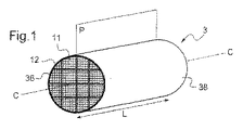
微粒子濾過器(1)は、従来から、長さL(典型的には10〜30cmの間)の長手方向軸C−Cを有する一般的に円柱状の濾過体(3)を少なくとも1つ備えており、該濾過体(3)は金属缶(5)内に挿入されている。 The particulate filter (1) conventionally comprises at least one generally cylindrical filter body (3) having a longitudinal axis C-C of length L (typically between 10 and 30 cm). The filter body (3) is inserted into a metal can (5).
良好な熱機械抵抗のおかげで、特に再生フェーズの間、継ぎ手(12)によって複数の「単位」濾過ブロック(11)と呼ばれているものをアセンブルし、続いて機械加工されることによって、この濾過体を製造することは有利である。濾過体は、したがって図1に示すように「組み立てられた」濾過体である。図2は、軸D−Dに沿う長さL、幅l、高さhの単位濾過ブロックの例を示している。 Thanks to the good thermomechanical resistance, this can be achieved by assembling what is called multiple “unit” filtration blocks (11) by means of a joint (12) and subsequently machined, especially during the regeneration phase. It is advantageous to produce a filter body. The filter body is thus a “assembled” filter body as shown in FIG. FIG. 2 shows an example of a unit filtration block having a length L, a width l, and a height h along the axis DD.
濾過体(3)はまた、一体型でありえて、すなわち図3に示されるように継ぎ目のない単一体として作られている。 The filter body (3) can also be unitary, i.e. made as a seamless single body as shown in FIG.
従来は、単位濾過ブロックまたは一体型濾過体を製造するために、セラミック(菫青石、炭化ケイ素、アルミナ、ムライト、窒化ケイ素、ケイ素/炭化ケイ素混合物など)が、ハニカム構造プリフォームを形成するように押し出しダイスを通して押し出される。 Conventionally, ceramics (such as cordierite, silicon carbide, alumina, mullite, silicon nitride, silicon / silicon carbide mixtures, etc.) are formed to form a honeycomb structure preform to produce unit filter blocks or integral filter bodies. Extruded through an extrusion die.
単位濾過ブロック(11)を製造するために、押し出しダイスは、プリフォームの側面(13)が4つのほぼ等しい側面(14a−d)を有するように従来は形付けられており、例えば、正方形、長方形または六角形の断面の並列パイプ状プリフォームを規定している。そのようなプリフォームの側面の幅lは、典型的には30mmから100mmの間である。 In order to produce the unit filtration block (11), the extrusion dies are conventionally shaped so that the side (13) of the preform has four approximately equal sides (14a-d), for example, square, It defines parallel pipe-shaped preforms with a rectangular or hexagonal cross section. The side width l of such a preform is typically between 30 mm and 100 mm.
一体型濾過体を製造するために、押出ダイスは、プリフォームが円形または楕円形断面の筒状の形状を有するように従来は形付けられている。 In order to produce an integral filter body, extrusion dies are conventionally shaped such that the preform has a cylindrical shape with a circular or elliptical cross section.
そして、プリフォームは焼結されて、ハニカム構造を形成する。 The preform is then sintered to form a honeycomb structure.
「ハニカム」構成は、プリフォームおよび多孔質構造が、隣接チャネル(18)の1組または「ダクト」を備えて、断面で市松模様を形成することを意味する。 A “honeycomb” configuration means that the preform and porous structure form a checkerboard pattern in cross-section, with a set of adjacent channels (18) or “ducts”.
その各々は側壁(22)によって境界を画された複数のチャネル(18)は、一般にはぼ正方形断面を有し、真っ直ぐであり、かつ互いに並列に延在する。一つの断面では、複数のチャネルは行(19)と列(20)を形成する。側壁の厚さは特に180〜500μmの間でありうる。チャネルの断面は特に0.4〜9mm2の間でありうる。 A plurality of channels (18), each of which is bounded by a side wall (22), generally has a square cross section, is straight, and extends parallel to each other. In one cross section, the plurality of channels form rows (19) and columns (20). The thickness of the side walls can in particular be between 180 and 500 μm. Channel cross-section may particularly be between 0.4~9mm 2.
プリフォームの各チャネルは、上流面(26e)上の上流開口部(24e)すなわち「流入面」を介して、およびを下流面(26s)上の下流開口部(24s)すなわち「流出面」を介して現れる。 Each channel of the preform has an upstream opening (24e) or “inflow surface” on the upstream surface (26e) and a downstream opening (24s) or “outflow surface” on the downstream surface (26s). Appears through.
用語「上流パターン」および「下流パターン」は、夫々上流および下流面に垂直な観測方向において見られる上流および下流面のイメージへを言う。図2においては、観測者(Oe)は上流パターンを観測し、観測者(Os)は下流パターンを観測する。 The terms “upstream pattern” and “downstream pattern” refer to images of the upstream and downstream planes seen in the observation direction perpendicular to the upstream and downstream planes, respectively. In FIG. 2, the observer (Oe) observes the upstream pattern, and the observer (Os) observes the downstream pattern.
全チャネルが同じ長さを有し、かつ上流および下流面が該上流および下流面でのチャネルの方向に垂直であるとき、かつチャネルが閉塞される前には、上流および下流パターンはそれ故にそれぞれ上流および下流面でチャネルの方向に垂直である断面に対応する。 When all the channels have the same length and the upstream and downstream surfaces are perpendicular to the direction of the channel at the upstream and downstream surfaces, and before the channel is closed, the upstream and downstream patterns are therefore each Corresponds to a cross section perpendicular to the direction of the channel on the upstream and downstream faces.
内側チャネル(18i)を周辺チャネル(18p)から区別することは従来からなされている。 It has been conventional to distinguish the inner channel (18i) from the peripheral channel (18p).
内側チャネル(18i)と違って、周辺チャネル(18p)の側壁は、ハニカム構造の外側に部分的に露出されている。長手方向エッジ(29)を有するハニカム構造において、および特に並列パイプ状ハニカム構造において、周辺チャネル(18p)の間において、隅チャネル(18p”)と側方チャネル(18p’)との間で、違いが作られる。隅チャネル(18p”)は上記長手方向エッジに沿って延在する。側方チャネル(18p’)は、隅チャネル(18p”)と違って、ハニカム構造の側壁(14a−d)のうち1つだけに沿って配置される。 Unlike the inner channel (18i), the side walls of the peripheral channel (18p) are partially exposed outside the honeycomb structure. Differences between the corner channels (18p ″) and the side channels (18p ′) in the honeycomb structure with the longitudinal edges (29) and in particular in the parallel pipe-like honeycomb structure between the peripheral channels (18p). The corner channel (18p ") extends along the longitudinal edge. The side channels (18p ') are arranged along only one of the sidewalls (14a-d) of the honeycomb structure, unlike the corner channels (18p ").
濾過体の製作を予定されるハニカム構造は、公知のように、上流プラグ(30s)と下流プラグ(30e)によって、それぞれ上流面(24e)にまたは下流面(24s)で交互に閉塞されて、「出口チャネル(18s)」および「入口チャネル(18e)」と呼ばれものをそれぞれ形成する(図4参照)。そして、得られたものは「濾過」ブロックである。 As is well known, the honeycomb structure to be manufactured for the filter body is alternately closed by the upstream surface (24e) or the downstream surface (24s) by the upstream plug (30s) and the downstream plug (30e), respectively. The so-called “exit channel (18s)” and “inlet channel (18e)” are respectively formed (see FIG. 4). The result is a “filter” block.
出口チャネル(18s)と入口チャネル(18e)の上流プラグ(30s)と下流プラグ(30e)に対するそれぞれの反対端部で、出口チャネル(18s)および入口チャネル(18e)は、それぞれ「出口開口部(32s)」と呼ばれる下流開口部、および「入口開口部(32e)」と呼ばれる上流開口部を介して外部に開いており、それぞれ下流面(26s)および上流面(26e)にわたり延在している。 At the opposite ends of the outlet channel (18s) and the inlet channel (18e) with respect to the upstream plug (30s) and the downstream plug (30e), the outlet channel (18s) and the inlet channel (18e) are respectively “outlet openings ( 32s) "and the upstream opening called" inlet opening (32e) "open to the outside and extend across the downstream face (26s) and upstream face (26e), respectively. .
それゆえに、入口チャネルおよび出口チャネルは、それぞれ入口室(34e)および出口室(34s)を規定し、各室は側壁(22)、閉塞プラグおよび外部に開く開口部によって境界を画されている。2つの隣接する入口および出口チャネルは、それらに共通の側壁を介して流体連絡状態にある。 Thus, the inlet and outlet channels define an inlet chamber (34e) and outlet chamber (34s), respectively, each chamber bounded by a side wall (22), a closure plug and an opening that opens to the outside. Two adjacent inlet and outlet channels are in fluid communication through their common sidewalls.
組み立てられた濾過体を製作するためには、一体型濾過ブロック(11)は、ブロックの向かい合う隣接面の間に入れられたセラミック接合セメントで作られた継ぎ手(12)によって該ブロックを結合することによって一緒に組み立てられる。該接合セメントは、一般には、シリカ及び/又は炭化ケイ素及び/又は窒化アルミニウムから成っている。好ましくは、接合セメントは、濾過されるべき排気ガスに対して実質的に不透過である。接合セメントは、熱機械応力を制限するために、20℃〜800℃の間において少なくとも0.1W/m.Kの熱伝導性を有しうる。典型的には、接合部(12)の平均厚さは0.3〜4mmの間である。 In order to produce an assembled filter body, the integral filter block (11) is joined by a joint (12) made of ceramic cemented cement placed between the adjacent faces of the block. Assembled together. The joining cement is generally made of silica and / or silicon carbide and / or aluminum nitride. Preferably the bonding cement is substantially impermeable to the exhaust gas to be filtered. The joining cement should be at least 0.1 W / m.s between 20 ° C. and 800 ° C. to limit thermomechanical stress. It may have a thermal conductivity of K. Typically, the average thickness of the joint (12) is between 0.3 and 4 mm.
接合セメントは、単位濾過ブロックの側面の全領域にわたって、またはこの側面の一部分にのみ施与されうる。特に後者の場合、単位濾過ブロックの全ての側面が、別の単位濾過ブロックの任意の側面へ常に見境なく組み立てられうるわけではない。換言すれば、側面が適切に対応した側面に互いに接着されることを確実にするために、単位濾過ブロックの1以上の側面を識別することが必要であろう。この目的のために、マークは、単位濾過ブロックの側面上にプリントされうる。 Bonding cement may be applied over the entire area of the side of the unit filtration block or only to a portion of this side. Especially in the latter case, not all sides of a unit filtration block can always be assembled to any side of another unit filtration block. In other words, it may be necessary to identify one or more sides of the unit filter block to ensure that the sides are properly bonded to the corresponding side. For this purpose, the mark can be printed on the side of the unit filter block.
それ故に、形成されたアセンブリは、缶(5)、例えば円形断面の円柱状濾過体を製作するための缶に整合された形状を得るために、機械加工されうる。 Therefore, the formed assembly can be machined to obtain a shape matched to the can (5), for example, a can for making a cylindrical filter of circular cross section.
一般に、周辺コーティング(36)、熱的に絶縁されかつ排気ガスに対して不透過であるコーティング要素から作られた「外部コーティング」または「コーティング」とも呼ばれる周辺コーティング(36)は、一体型または組み立てられた濾過体の側表面(38)に施与される。 Generally, the peripheral coating (36), which is also referred to as an “external coating” or “coating” made from a coating element that is thermally insulated and impervious to exhaust gases, is integrated or assembled. Applied to the side surface (38) of the filter body.
そして、組み立てられたまたは一体型の濾過体(3)は、缶(5)および周辺継ぎ手(40)に挿入されえ、該周辺継ぎ手(40)は、排気ガスに対して不透過性を有し、濾過体の側表面(38)と缶(5)との間に置かれる。 The assembled or integral filter body (3) can then be inserted into the can (5) and the peripheral joint (40), the peripheral joint (40) being impermeable to exhaust gases. , Placed between the side surface (38) of the filter body and the can (5).
入口チャネルの入口開口部を介する濾過体(3)間の排気ガスの流れ(F)は、出口チャネルで再結合される前に、これらのチャネルの側面濾過壁を通り過ぎ、そして出口開口部を介して外部に逃れる。 The exhaust gas flow (F) between the filter bodies (3) through the inlet openings of the inlet channels passes through the side filtration walls of these channels and is routed through the outlet openings before being recombined at the outlet channels. Escape to the outside.
使用の一定期間後には、濾過体(3)の入口チャネル内に蓄積されている微粒子または「煤粒子」は、濾過体(3)による圧力低下を増大させ、その結果エンジンの性能を損なう。この理由のために、濾過体は定期的に、例えば500km毎に再生されなければならない。 After a certain period of use, the particulates or “soot particles” that have accumulated in the inlet channel of the filter body (3) increase the pressure drop due to the filter body (3) and consequently impair the performance of the engine. For this reason, the filter body must be regenerated regularly, for example every 500 km.
再生または「閉塞解除」操作は、煤粒子を燃焼させうる温度まで煤粒子を加熱することによって、煤粒子を酸化することから成る。 The regeneration or “deocclusion” operation consists of oxidizing the soot particles by heating the soot particles to a temperature at which they can burn.
再生フェーズの間、温度は濾過体(3)の領域に沿って異なり、一様には変化しない。これは、排気ガスが、煤の燃焼により放出された熱エネルギーを下流端へ転送するからである。さらに、煤は様々なチャネル中に一様に堆積されず、煤は、例えば好ましく濾過体の長手方向軸(また濾過体の「中心部」と呼ばれる)に近い領域内に蓄積される。燃焼領域は、したがって濾過体(3)内に一様に分布させられるものではない。煤の燃焼は、したがって周辺部での温度上昇よりも大きな温度上昇を濾過体の中心部で起こす。最後に、濾過体(3)の周辺領域は、周りの空気によって、金属缶(5)を通して冷却される。 During the regeneration phase, the temperature varies along the region of the filter body (3) and does not change uniformly. This is because the exhaust gas transfers the thermal energy released by soot combustion to the downstream end. Furthermore, the soot is not uniformly deposited in the various channels, and soot accumulates, for example, in a region that is preferably close to the longitudinal axis of the filter body (also referred to as the “center” of the filter body). The combustion zone is therefore not evenly distributed in the filter body (3). Soot burning therefore causes a temperature rise in the center of the filter body that is greater than the temperature rise in the periphery. Finally, the surrounding area of the filter body (3) is cooled through the metal can (5) by the surrounding air.
濾過体(3)内の温度の不均一性は、局所的な破断またはひび割れを起こし得るところの、大きな振幅の局所的な応力を発生する。したがって、濾過体(3)は、交換されねばならず、使用済みの濾過体は、好ましくはリサイクルされる。 The non-uniformity of temperature in the filter body (3) generates large amplitude local stresses that can cause local breaks or cracks. Thus, the filter body (3) must be replaced and the used filter body is preferably recycled.
濾過体の寿命を延ばすために、入口チャネルから残灰を取除くために徹底した清掃を実行することも可能である。従来から「灰除去」と呼ばれたこの清掃作業は、重量運搬の車両向けの濾過体のために特に実行される。この作業は、濾過体を排気ラインから取除くことおよび濾過体から残存物を除去するために車両の外部の清掃装置を使うことを従来から含んでいる。 In order to extend the life of the filter body, it is also possible to perform a thorough cleaning to remove residual ash from the inlet channel. This cleaning operation, conventionally referred to as “ash removal”, is particularly carried out for filters for heavy-duty vehicles. This operation conventionally involves removing the filter body from the exhaust line and using a cleaning device external to the vehicle to remove residue from the filter body.
外部での再生またはリサイクル作業のどちらのためであろうと、濾過体の上流および下流面が迅速に識別されうることが必要である。 Whether for external regeneration or recycling operations, it is necessary that the upstream and downstream surfaces of the filter body can be quickly identified.
したがって、ハニカム構造に対してこの識別が必要である。 Therefore, this identification is necessary for the honeycomb structure.
本発明は、側面並びに上流および下流面によって境界を画されたハニカム構造を提案しており、上記ハニカム構造は隣接チャネルの1組みを備えており、各チャネルは上流および下流面上に、それぞれ上記上流および下流開口部を介して現れて、チャネルの上記組みは、上流および下流面上にそれぞれ上流および下流パターンを形成する。 The present invention proposes a honeycomb structure bounded by side surfaces and upstream and downstream surfaces, the honeycomb structure comprising a set of adjacent channels, each channel on the upstream and downstream surfaces respectively. Appearing through the upstream and downstream openings, the set of channels forms upstream and downstream patterns on the upstream and downstream surfaces, respectively.
本発明によれば、該上流面および下流面の少なくとも1つは、上流および下流パターンのいずれかが他方の上に完全に重ね合わされることを不可能にする誤り防止マーク(M)を有しており、該上流及び/又は下流パターンの外周囲は対称であるかまたは10未満、または5未満または3未満のチャネルにわたり延在する非対称性を有している。 According to the invention, at least one of the upstream and downstream surfaces has an error prevention mark (M) that makes it impossible for either of the upstream and downstream patterns to be completely superimposed on the other. And the outer perimeter of the upstream and / or downstream pattern is symmetrical or has an asymmetry extending over less than 10, or less than 5 or less than 3 channels.
言い換えれば、もし上流パターンと下流パターンとを重ね合わせることが試みられても、以下のようになるこれらのパターンの位置を見つけることは不可能である:
該上流パターンは、如何なる点でも、該下流パターンを超えて突出(project)しない、および、
該下流パターンは、如何なる点でも、該上流パターンを超えて突出(project)しない。
In other words, if an attempt is made to superimpose the upstream and downstream patterns, it is impossible to find the position of these patterns as follows:
The upstream pattern does not project beyond the downstream pattern in any way; and
The downstream pattern does not project beyond the upstream pattern at any point.
本記載の残りにおいて詳細が分かるように、上流および下流面の簡単な1つの観察が、誤り防止マークの存在または非存在を検出することを可能にし、したがって、観察された面を素早く確実に識別することを可能にする。 As will be seen in detail in the remainder of this description, a simple observation of the upstream and downstream surfaces makes it possible to detect the presence or absence of error prevention marks and thus quickly and reliably identify the observed surface Make it possible to do.
加えるに、誤り防止マークは、規定によって、ハニカム構造の形状の特徴から生じる。したがって、誤り防止マークが、例えばインクの場合のように消去されるリスクはない。 In addition, error-proof marks, by convention, arise from the shape characteristics of the honeycomb structure. Therefore, there is no risk that the error prevention mark is erased as in the case of ink, for example.
上流及び/又は下流パターンの外周囲は、それが非対称のとき、10未満、5未満または3未満のチャネルにわたって延在するところの非対称性を有するという特徴は、もし上記チャネルによって境界を画された外周囲のその部分が考慮されなければ、該外周囲は対称であることを意味している。 The feature that the outer perimeter of the upstream and / or downstream pattern has asymmetry that extends over less than 10, less than 5, or less than 3 channels when it is asymmetric is bounded by said channels If that part of the outer periphery is not taken into account, it means that the outer periphery is symmetrical.
本発明に従うハニカム構造は、以下の任意的な特徴の1以上を備えうる:
-上流および下流パターンの少なくとも1つは対称軸を有さない。好ましくは、これらのパターンのいずれも対称軸を有さない;
-該誤り防止マークは、50未満、30未満、20未満、15未満、10未満、5未満のチャネルまたは単一チャネルにわたって延在する。上記上流及び/又は下流面上の少なくとも1つの誤り防止マークの面積は、上記面の面積の10%未満、5%未満、3%未満、または1%未満を示す;
-該誤り防止マークは、ハニカム構造の周辺部上に延在し、またはハニカム構造の周辺部上にもっぱら延在する;
-該誤り防止マークは、上記上流および下流面の少なくとも1つから、ハニカム構造の長さ(L)の10%未満、5%未満、2%未満または1%未満、及び/又は0.1%超、0.3%超、0.5%超の深さにわたって延在する;
-該誤り防止マークは維持される、すなわち、ハニカム構造が焼結される間、特に後に記載される焼結条件の下で焼結される間に、該誤り防止マークは見うるままである;
-該誤り防止マークは、1以上のチャネルの特定の形状から生じる。特に、誤り防止マークは、特定のアスペクト比から、および特にこれら以外のチャネルのアスペクト比の平均から少なくとも5%、または少なくとも8%、または少なくとも12%異なっているアスペクト比から生じる;
-該誤り防止マークは、1以上の開口部の特定の配置、例えば厚さの変化からまたはこの(これら複数の)開口部の端の変形からから生じる;好ましくは、該誤り防止マークは、問題のチャネルまたは複数チャネルの開口部内に隅若しくは追加の壁を創り出さない;
-該誤り防止マークを形成する該チャネルまたは複数チャネルは、上流及び/又は下流面で、これら以外のチャネルの平均壁厚から少なくとも10%、好ましくは少なくとも20%違っている平均壁厚を有している;
-該誤り防止マークを形成する該チャネルまたは複数チャネルは、上流及び/又は下流面で、これ以外のチャネルの平均開口部面積から少なくとも1%、好ましくは少なくとも20%、少なくとも30%違っている平均開口部面積を有している;
-該誤り防止マークを形成する該チャネルまたは複数チャネルは、上流及び/又は下流面で、これ以外のチャネルの外及び/又は内周囲とは異なる外及び/又は内周囲を有する。特に、該チャネル、または誤り防止マークを形成しているチャネルのグループのチャネルの少なくとも1つは、これ以外のチャネルとは異なる非対称性を有する;
-該誤り防止マークは、ハニカム構造の側面に排他的には備えられないか、または上記側面には備えられない;
-少なくとも1つの断面において、好ましくは任意の断面において、該チャネルは行と列の形に配列され、各中間壁は、波打つ形状を有するチャネルの2つの行または2つの列を分離し、上記断面で測られた非対称度は、好ましくは40%未満、好ましくは30%未満である;
-該ハニカム構造は、一定の断面を有している、すなわち、断面は問題の断面平面が何であろうとも全く同一である。
-単一の誤り防止マークが、上流面または下流面に置かれうる。また、2つの異なる誤り防止マークが、またそれぞれ上流面および下流面に置かれうる;
-誤り防止マークは意味を示す標識、例えば矢印または文字、例えば上流面を示すために文字「E」を形成しうる。
-ハニカム構造の外側へ曝されないチャネルのいずれも、それらは「内部チャネル」と呼ばれるが、上流面または下流面上のどちらでも、これ以外の任意の内部チャネルの開口面積の7%を超え、好ましくは15%を超え、より好ましくは20%を超えて異なる開口面積をもたない。該誤り防止マークは、内部チャネルの全てがほぼ同じ面積の開口部を有する場合に特に有用である。開口部の間の小さな差異は、実際には第1チャネルを第2チャネルから区別することを困難にする;
-該ハニカム構造のチャネルのいずれも、上流面または下流面上で、それ以外のチャネルの任意の1つの開口面積の7%を超え、好ましくは15%を超え、より好ましくは20%を超えて異なる開口面積をもたない。
-該チャネル密度は、7.75を超え、15を超え,及び/又は100チャネル未満、または60チャネル未満である(横断領域の毎cm2当たり、すなわち上流面または下流面でのcm2当たり);
-ハニカム構造中のチャネル数は100を超え及び/又は2000未満である;
-該ハニカム構造は、直通チャネル、すなわち流体の流れを妨げがちなプラグを持たないチャネルのみを備える;
-該ハニカム構造は、柱状外形を有し、その断面は5cm2を超え及び/又は40cm2未満の面積をもつ;
-該ハニカム構造は、多角形の柱状外形を有し、特に方形または六角形の断面を有し、上記多角形断面の片側の幅は30mmを超え、及び/又は100mm未満である;
-該ハニカム構造は、長手方向対称性を有する少なくとも1つの平面を備える外形を有する。該ハニカム構造は、従来技術の特定の一体型濾過体のハニカム構造の場合のように、丸いまたは楕円形断面の柱状形を特に有し、あるいは、従来技術の特定の単位濾過ブロックのハニカム構造の場合のように、方形断面の柱状形を有する。このタイプのハニカム構造にとって、該上流および下流面の区別は、実際のところ一般的には特につけにくいものである;
-該ハニカム構造は、焼結材料を備え、または焼結材料から構成される;
-該ハニカム構造の材料はセラミックである;
-該ハニカム構造は単一の材料から成る(例えば、組み立てられた単位濾過ブロックの材料とは違った性質の接合セメントによって組み立てられた濾過体とは異なり);
-該誤り防止マークは、該ハニカム構造の残りと同じ材料から作られる;
-該ハニカム構造は押し出された構造体である;および
-該ハニカム構造の材料は、10%を超える、好ましくは30%を超える、さらに40%を超える、さらに50%を超える、及び/又は80%未満、または70%未満の総多孔率を有する。
A honeycomb structure according to the present invention may comprise one or more of the following optional features:
-At least one of the upstream and downstream patterns does not have an axis of symmetry. Preferably, none of these patterns has an axis of symmetry;
- The error protection mark, less than 50, less than 30, less than 20, less than 15, less than 10, extends over less than 5 channels or single channel. The area of the at least one error prevention mark on the upstream and / or downstream surface represents less than 10%, less than 5%, less than 3%, or less than 1% of the area of the surface;
- The error protection mark extends over a peripheral portion of the honeycomb structure, or exclusively extend on the peripheral portion of the honeycomb structure;
- The error protection mark, from at least one of said upstream and downstream surfaces, the length of the honeycomb structure less than 10% of (L), less than 5%, less than 2% or 1%, and / or 0.1% Extending over a depth of greater than 0.3%, greater than 0.5%;
- The error protection mark is maintained, i.e., while the honeycomb structure is sintered, while being sintered under the sintering conditions described later in particular, the error protection mark remains may see;
- The error protection mark results from the particular shape of one or more channels. In particular, error-proof marks arise from specific aspect ratios, and in particular from aspect ratios that differ by at least 5%, or at least 8%, or at least 12% from the average of other channel aspect ratios;
- The error protection mark, one or more specific arrangement of the openings, for example, from a change in the thickness or the results from the deformation of the end of (the plurality of) openings; preferably, the error protection mark, question Does not create corners or additional walls in the channel or multiple channel openings;
- the channel or channels forming the error protection mark, upstream and / or downstream surface, at least 10% from the average wall thickness of these other channels, preferably has an average wall thickness that differs by at least 20% ing;
- average the channel or channels forming the error protection mark, upstream and / or downstream surface, at least 1% from the average opening area of the other channel, which are preferably at least 20%, unlike at least 30% Has an opening area;
- the channel or channels forming the error protection mark, upstream and / or downstream surface, has a different outer and / or inner circumference and the outer and / or inner periphery of the other channels. In particular, at least one of the channels or a group of channels forming an error prevention mark has a different asymmetry from the other channels;
- The error protection mark, either on the side face of the honeycomb structure is not provided in the exclusive, or not provided in the side surface;
In at least one cross section, preferably in any cross section, the channels are arranged in rows and columns, each intermediate wall separating two rows or two columns of channels having a wavy shape, The asymmetry measured at is preferably less than 40%, preferably less than 30%;
The honeycomb structure has a constant cross section, ie the cross section is exactly the same whatever the cross section plane in question.
-A single error prevention mark can be placed on the upstream or downstream side. Also, two different error prevention marks can be placed on the upstream and downstream surfaces respectively;
The error prevention mark may form a sign indicating meaning, for example an arrow or a letter, for example the letter “E” to indicate the upstream face.
-Any of the channels that are not exposed to the outside of the honeycomb structure are referred to as "internal channels", but preferably more than 7% of the open area of any other internal channel, either on the upstream or downstream side, preferably Does not have a different open area more than 15%, more preferably more than 20%. The error protection marks are particularly useful when all of the internal channels have a substantially openings of the same area. The small difference between the openings actually makes it difficult to distinguish the first channel from the second channel;
-Any of the channels of the honeycomb structure on the upstream or downstream surface is greater than 7%, preferably greater than 15%, more preferably greater than 20% of any one of the other channels open area Does not have a different opening area.
- The channel density is greater than 7.75, more than 15, and / or less than 100 channels, or less than 60 channels (per cm 2 per cross area, namely per cm 2 on the upstream side or downstream side) ;
The number of channels in the honeycomb structure is greater than 100 and / or less than 2000;
The honeycomb structure comprises only direct channels, i.e. channels without plugs that tend to impede fluid flow;
The honeycomb structure has a columnar profile, the cross section of which has an area greater than 5 cm 2 and / or less than 40 cm 2 ;
The honeycomb structure has a polygonal columnar profile, in particular a square or hexagonal cross section, the width of one side of the polygonal cross section being greater than 30 mm and / or less than 100 mm;
The honeycomb structure has an outer shape with at least one plane having longitudinal symmetry; The honeycomb structure particularly has a columnar shape with a round or elliptical cross section, as in the case of the honeycomb structure of a specific integral filter body of the prior art, or the honeycomb structure of a specific unit filtration block of the prior art. As in the case, it has a columnar shape with a square cross section. For this type of honeycomb structure, the distinction between the upstream and downstream surfaces is in fact generally difficult to apply;
The honeycomb structure comprises or consists of a sintered material;
The material of the honeycomb structure is ceramic;
The honeycomb structure consists of a single material (for example, unlike a filter body assembled with bonded cement of a different nature than the assembled unit filter block material);
- The error protection mark are made of the same material as the rest of the honeycomb structure;
The honeycomb structure is an extruded structure; and
The material of the honeycomb structure has a total porosity of greater than 10%, preferably greater than 30%, even greater than 40%, even greater than 50%, and / or less than 80%, or less than 70%.
1実施態様においては、本発明に従うハニカム構造は、第1と第2の隣接チャネルの瓦状に重なった複数の組を備え、これらチャネルは、断面において、好ましくは規則的なパターン、一層好ましくは市松模様を形成するように配列されている:
-上記第1チャネルの累積総容積は、上記第2チャネルの累積総容積よりも大きい、及び/又は
-該上流および下流面の少なくとも1つの面上の該第1チャネルの開口部の累積総面積は、上記上流および下流面のもう他方の面上の該第2チャネルの開口部の累積した総面積よりも大きい;
-該第1チャネルは、好ましくは一定の第1断面を有し、該第2チャネルは、
好ましくは一定の第2断面を有し、そして該第1断面は該第2断面とは異なっている。
In one embodiment, the honeycomb structure according to the invention comprises a plurality of sets of tiled layers of first and second adjacent channels, the channels preferably having a regular pattern in cross section, more preferably Arranged to form a checkered pattern:
The cumulative total volume of the first channel is greater than the cumulative total volume of the second channel, and / or
The cumulative total area of the opening of the first channel on at least one face of the upstream and downstream faces is the cumulative total area of the opening of the second channel on the other face of the upstream and downstream faces; Greater than;
The first channel preferably has a constant first cross section, and the second channel is
Preferably it has a constant second cross section, and the first cross section is different from the second cross section.
「規則的なパターン」は、例え誤り防止マークを形成するパターンの領域が他のチャネルとは異なる対称性を有していても、該第1および第2チャネルがお互いに対して同じように常に配置されているパターンである。濾過要素の高さと幅にわたる、該第1と第2チャネルの交互の配列は、それ故に市松模様の形の規則的なパターンを形成する。 “Regular pattern” means that the first and second channels are always in the same way with respect to each other, even if the area of the pattern forming the error-proof mark has a different symmetry from the other channels. It is a pattern that is arranged. The alternating arrangement of the first and second channels across the height and width of the filtering element thus forms a regular pattern in a checkerboard shape.
本発明に従うそのようなハニカム構造は、また1以上の以下の任意的な特徴を有しうる:
-該第1チャネル及び/又は第2チャネルの断面は、上記チャネルに沿って一定である;
-上記第1および第2チャネルは一直線で平行である;
-該第1チャネルの累積総容積Veの該第2チャネルの累積総容積Vsに対する比rは、1.03より大きく、1.10より大きく、1.15より大きく及び/又は3未満、2.5未満、好ましくは2未満である;
-該第1チャネルの累積総内面積の該第2チャネルの累積内面積に対する比r’は、1.03より大きく、1.10より大きく、1.15より大きく及び/又は3未満、2.5未満、好ましくは2未満である;
-該第1チャネルの平均水力直径(すなわち、これらのチャネルの全てにわたる)の該第2チャネルの平均水力直径に対する比は、1.03より大きく、1.10より大きく、1.15より大きく及び/又は1.8未満、1.3未満、好ましくは1.2未満である;
-好ましくは、上流および下流面の少なくとも1つの面上で測られる非対称度は、30%未満、好ましくは20%以下、および一層好ましくは15%以下である;
-上流および下流面の少なくとも1つ、好ましくは上流および下流面の各々は、平坦で一般的な形状を有している。それゆえに、例えば、チャネルは、これらの面の1つに備えられるであろうスロットの底へ開いていない。誤り防止マークの存在は、10%未満、5%未満、3%未満、または1%未満で、該第2チャネルから該第1チャネルを分離している総壁領域を変更する。この領域は、濾過を予定された構造の場合、その領域が第1と第2チャネルとの間であるときは、濾過されるべき流体がそこを通過する領域に対応している。
Such a honeycomb structure according to the present invention may also have one or more of the following optional features:
The cross section of the first channel and / or the second channel is constant along the channel;
The first and second channels are straight and parallel;
The ratio r of the cumulative total volume Ve of the first channel to the cumulative total volume Vs of the second channel is greater than 1.03, greater than 1.10, greater than 1.15 and / or less than 3. Less than 5, preferably less than 2;
The ratio r ′ of the cumulative total internal area of the first channel to the cumulative internal area of the second channel is greater than 1.03, greater than 1.10, greater than 1.15 and / or less than 3. Less than 5, preferably less than 2;
The ratio of the average hydraulic diameter of the first channel (ie across all of these channels) to the average hydraulic diameter of the second channel is greater than 1.03, greater than 1.10, greater than 1.15; / Or less than 1.8, less than 1.3, preferably less than 1.2;
-Preferably the degree of asymmetry measured on at least one of the upstream and downstream faces is less than 30%, preferably not more than 20% and more preferably not more than 15%;
-At least one of the upstream and downstream surfaces, preferably each of the upstream and downstream surfaces, is flat and has a general shape. Thus, for example, the channel is not open to the bottom of the slot that would be provided on one of these faces. The presence of error prevention marks changes the total wall area separating the first channel from the second channel by less than 10%, less than 5%, less than 3%, or less than 1%. This region corresponds to the region through which the fluid to be filtered passes if the region is between the first and second channels for a structure intended for filtration.
本発明に従うそのようなハニカム構造は、一体型濾過体、または組み立てられた濾過体を形成するように、組み立てられることが予定された単位濾過ブロックの製作に特に使われうる。該第1および第2チャネルは、下流および上流面上でそれぞれ塞がれ、それ故に、それぞれ入口および出口チャネルに成る。「濾過要素」は、一般に本発明に従えば、一体型濾過体または単位濾過ブロックである。 Such a honeycomb structure according to the invention can be used in particular for the production of unitary filter blocks that are intended to be assembled to form an integral filter body or an assembled filter body. The first and second channels are plugged on the downstream and upstream surfaces, respectively, and thus become inlet and outlet channels, respectively. The “filter element” is generally an integral filter body or unit filter block according to the present invention.
本発明に従う濾過要素は、隣接する第1および第2チャネルの、瓦のように部分的に重ねられた組を特に備えることができ、該チャネルは上記濾過要素の上流面から下流面へ延在し、各第1チャネルは上流開口部を介して上流面へ開き且つ下流面で閉塞され、そして各第2チャネルは下流開口部を介して下流面へ開き且つ上流面で閉塞されている。 The filtering element according to the invention can in particular comprise a set of adjacent first and second channels, partially overlapped like tiles, which channels extend from the upstream surface to the downstream surface of the filtering element Each first channel opens to the upstream surface through the upstream opening and is blocked at the downstream surface, and each second channel opens to the downstream surface through the downstream opening and is blocked at the upstream surface.
以下に示されるように、プラグは、上流面を下流面から区別するのを容易にするために有利に使われうる。 As shown below, the plug can be advantageously used to facilitate distinguishing the upstream surface from the downstream surface.
1の特別な実施態様においては、濾過要素の第1チャネルの数は第2チャネルの数とは異なっている。 In one particular embodiment, the number of first channels of the filtering element is different from the number of second channels.
好ましくは、第1チャネルの数は、第2チャネルの数の20%未満、10%未満、5%未満、1%未満だけ異なっている。 Preferably, the number of first channels differs by less than 20%, less than 10%, less than 5%, less than 1% of the number of second channels.
1の特別な実施態様においては、隣接する第1および第2チャネルの瓦のように部分的に重ねられた組は、上流および下流面の少なくとも1つに、好ましくは上流および下流面に、「不規則」領域と呼ばれる少なくとも1つの領域を除いて、規則的なパターン、好ましくは市松模様を形成する。したがって、この不規則領域においては、該第1および第2チャネルの配列の規則性は中断される。 In one particular embodiment, a partially overlapped set, such as adjacent first and second channel roof tiles, is located on at least one of the upstream and downstream surfaces, preferably on the upstream and downstream surfaces. A regular pattern, preferably a checkered pattern, is formed except for at least one region called the “irregular” region. Therefore, the regularity of the arrangement of the first and second channels is interrupted in this irregular region.
好ましくは、本発明に従う濾過要素は、30未満、20未満、10未満、5未満または2未満、好ましくは唯一の不規則領域を備えている。好ましくは、不規則領域は、30未満、20未満、10未満、5未満または2未満、好ましくは唯一のチャネルを占める。 Preferably, the filtration element according to the invention comprises less than 30, less than 20, less than 10, less than 5, less than 2, preferably only one irregular region. Preferably, the irregular regions occupy less than 30, less than 20, less than 10, less than 5, less than 2, or preferably only one channel.
1実施態様においては、不規則領域の創出は1つのチャネルのタイプの反転を引き起こす。規則的なパターンに依存して、その1つのチャネルは、「第2」チャネルである「第1」チャネルでなければならない。市松模様においては、そのような不規則領域は、プラグによって上流および下流面の1つに形成された十字形の、および開口部によって上流および下流面の他方の面に形成された十字形の出現に導きうる。 In one embodiment, the creation of irregular regions causes a reversal of one channel type. Depending on the regular pattern, that one channel must be the “first” channel, which is the “second” channel. In a checkered pattern, such irregular regions are the appearance of a cross formed on one of the upstream and downstream surfaces by a plug and a cross formed on the other of the upstream and downstream surfaces by an opening. Can lead to
本実施態様においては、不規則領域は、単一チャネル上にのみ延在し、したがって有利には濾過要素の働きを実質的に乱すことはできない。 In this embodiment, the irregular region extends only on a single channel and therefore advantageously cannot substantially disturb the function of the filtering element.
濾過要素は、多角形または丸められた、例えば円形または楕円断面の柱状外形を有しうる。 The filter element can have a columnar profile that is polygonal or rounded, for example with a circular or elliptical cross section.
1実施態様においては、不規則領域は、1の内部チャネルを占めうる。 In one embodiment, the irregular region may occupy one internal channel.
濾過要素が、単位濾過ブロックであるときは、不規則領域が周辺チャネルだけに広がることは、しかしながら好ましい。組み立て後にセメントと接触する周辺チャネルは、したがって、内部チャネルの濾過効率よりも低い濾過効率を有する。1以上の周辺チャネルを占める不規則領域を創り出すことは、したがって、組み立てられた濾過体の濾過効率のより小さい低下をもたらす。 When the filtration element is a unit filtration block, it is however preferred that the irregular area extends only to the peripheral channel. The peripheral channel that comes into contact with the cement after assembly therefore has a filtration efficiency that is lower than the filtration efficiency of the internal channel. Creating an irregular region occupying one or more peripheral channels therefore results in a smaller reduction in the filtration efficiency of the assembled filter body.
1の特別な実施態様においては、濾過要素は多角形断面の柱状外形を有し、
かつハニカム構造の側面の少なくとも1つにおいて、周辺チャネルの数は奇数である。
In one particular embodiment, the filtration element has a columnar profile with a polygonal cross section,
And in at least one of the side surfaces of the honeycomb structure, the number of peripheral channels is an odd number.
したがって、チャネルの交互の閉塞は、2つの上流および下流面の一方のみに、この側面の端での2つの周辺チャネル、すなわちこの側面の2つの隅チャネルの閉塞を生じる。それ故に、上流面を下流面と区別することは容易になる。 Thus, alternate blockage of the channel results in blockage of the two peripheral channels at the end of this side, i.e. the two corner channels of this side, on only one of the two upstream and downstream faces. Therefore, it becomes easy to distinguish the upstream surface from the downstream surface.
側面に沿う奇数個の周辺チャネルは、出口チャネルまたは入口チャネルの数よりもそれぞれ大きな数の入口チャネルまたは出口チャネルを生じうる。そのような特徴は、したがって、性能最適化に反すると考えられるであろう。しかし、発明者は、入口および出口チャネルの数の差が、重要ではなく有意な効果を持たないことを発見した。 An odd number of peripheral channels along the side can yield a larger number of inlet channels or outlet channels, respectively, than the number of outlet channels or inlet channels. Such a feature would therefore be considered contrary to performance optimization. However, the inventor has discovered that the difference in the number of inlet and outlet channels is not significant and has no significant effect.
1実施態様においては、ハニカム構造の少なくとも2つの側面にわたって、好ましくはハニカム構造の全ての側面上で、周辺チャネルの数は奇数である。 In one embodiment, the number of peripheral channels is an odd number over at least two sides of the honeycomb structure, preferably on all sides of the honeycomb structure.
ハニカム構造は、特に、矩形、方形または六角形断面の柱状外形を有しうる。上記断面の1つの側の幅は、特に30mmを超え、及び/又は100mm未満でありうる。 The honeycomb structure may in particular have a columnar profile with a rectangular, square or hexagonal cross section. The width of one side of the cross-section can in particular be greater than 30 mm and / or less than 100 mm.
本発明はまた、対称軸を有しない市松模様の流れ断面を有する押し出しダイスに関する。 The invention also relates to an extrusion die having a checkered flow cross section having no axis of symmetry.
市松模様にすることは、ハニカム構造が押し出しによって製造されることを可能にする。そのような市松模様にすることで、対称軸の無いことが、単純な押し出しによって本発明に従うハニカム構造を得ることを可能にする。 The checkered pattern allows the honeycomb structure to be manufactured by extrusion. With such a checkered pattern, the absence of a symmetry axis makes it possible to obtain a honeycomb structure according to the present invention by simple extrusion.
押し出しダイスはまた、本発明に従うハニカム構造の任意的な1以上の特徴を簡単な押し出しにより得ることができるようにデザインされうる。 The extrusion die can also be designed so that any one or more features of the honeycomb structure according to the invention can be obtained by simple extrusion.
本発明はまた、本発明に従うハニカム構造の位置決めの工程を含む方法に関しており、本方法においては、上流及び/又は下流面は上記ハニカム構造上の誤り防止マークを観察することによって識別され、そして該ハニカム構造は上記識別に従って位置決めされる。 The invention also relates to a method comprising the step of positioning a honeycomb structure according to the invention, in which the upstream and / or downstream surfaces are identified by observing the error-proof marks on the honeycomb structure, and The honeycomb structure is positioned according to the identification.
位置決めは、ハニカム構造を長手方向に沿って及び/又は該長手方向の周りに配位するように実行されうる。 Positioning can be performed to coordinate the honeycomb structure along and / or around the longitudinal direction.
本方法は、特に
-上記ハニカム構造のチャネルを閉塞する方法;
-上記ハニカム構造を清掃する方法、特に残留灰を部分的にまたは完全に除去するために清掃する方法;
-上記ハニカム構造に触媒コーティングを施与する方法;
-周辺コーティング、特に排気ガスに対して不透過性である断熱的コーティングセメントからつくられた周辺コーティングを施与する方法;
-本発明に従うハニカム構造を備えている濾過体を自動車の排気ラインまたはそのような排気ラインとして予定されたケーシングに搭載する方法;
-組み立てられた濾過体を構成するように、本発明に従うハニカム構造を備える複数の単位濾過ブロックを組み立てる方法;上流及び/又は下流面の識別は、特に大規模工業生産のために、有利には自動化される、
から選択されうる。
This method is
-A method of plugging the channels of the honeycomb structure;
-A method for cleaning the honeycomb structure, in particular for removing partial or complete residual ash;
-A method of applying a catalyst coating to the honeycomb structure;
Applying a peripheral coating, in particular a peripheral coating made from an adiabatic coating cement which is impermeable to exhaust gases;
A method for mounting a filter body comprising a honeycomb structure according to the invention in an exhaust line of a motor vehicle or a casing intended for such an exhaust line;
A method of assembling a plurality of unit filter blocks comprising a honeycomb structure according to the invention to constitute an assembled filter body; identification of upstream and / or downstream surfaces is advantageous, especially for large-scale industrial production Automated,
Can be selected.
本発明はまた、排気ガス、特に自動車の内燃エンジンからの排気ガスの汚染制御のための本発明に従うハニカム構造の使用、および熱交換器におけるそのような構造の使用に関する。 The invention also relates to the use of honeycomb structures according to the invention for the control of pollution of exhaust gases, in particular exhaust gases from automotive internal combustion engines, and the use of such structures in heat exchangers.
本発明はまた、次の連続する工程;
a)ハニカムプリフォームを形成するようにダイスを通してセラミックを押し出すこと、および
b)焼結されたハニカム構造を得るために上記プリフォームを乾燥させかつ焼結させること、
を含む、ハニカム構造の製造のための過程に関する。
The present invention also includes the following sequential steps;
a) extruding the ceramic through a die to form a honeycomb preform; and b) drying and sintering the preform to obtain a sintered honeycomb structure.
To a process for the manufacture of honeycomb structures.
1実施態様においては、ダイスは、本発明に従う押し出しダイスである。この場合、プリフォームは、本発明に従うハニカム構造を構成する。 In one embodiment, the die is an extrusion die according to the present invention. In this case, the preform constitutes a honeycomb structure according to the present invention.
1実施態様においては、焼結前または後に、好ましくは焼結前に、誤り防止マークは、材料の変形及び/又は除去及び/又は追加によって備えられる。 In one embodiment, the error-proof marks are provided by deformation and / or removal and / or addition of material before or after sintering, preferably before sintering.
本発明に従う押し出しダイスの使用は、特定の形成用具、例えばチャネルまたはチャネルのグループを局所的に変形するための用具を使用せねばならないことを避けるので好ましい。さらに、製造工程において追加の工程を要しない。 The use of an extrusion die according to the present invention is preferred because it avoids having to use certain forming tools, such as tools for locally deforming channels or groups of channels. Furthermore, no additional steps are required in the manufacturing process.
ダイスは、押し出し中に誤り防止マークを作り出すようにデザインされた一片のダイスでありうる。 The die can be a piece of die designed to create error prevention marks during extrusion.
1実施態様においては、穴を塞ぐダイス用のフレームまたはクサビは、押し出しの間に誤り防止マークを作り出すために、ダイスの下流に配置される。有利には、同じダイスが、それ故に上記穴を塞ぐフレームまたはクサビを備えるか否かに依存して、本発明に従うハニカム構造、または本発明に従わないハニカム構造を製作するために役立つ。 In one embodiment, a die frame or wedge that closes the hole is placed downstream of the die to create an error prevention mark during extrusion. Advantageously, depending on whether the same die is therefore provided with a frame or wedge that closes the hole, it serves to fabricate a honeycomb structure according to the invention or a honeycomb structure not according to the invention.
本発明に従う方法に従って、本発明に従うダイスによって製作された、焼結されていたハニカム構造のプリフォームは、本発明に従うハニカム構造そのものである。 The sintered honeycomb structure preform produced by the die according to the invention according to the method according to the invention is the honeycomb structure itself according to the invention.
本発明は、濾過要素を製作するための工程に関し、次の連続する工程:
a’)ダイスを通してセラミックを押し出してハニカム構造を形成すること、
b’)上記プリフォームを乾燥および焼結して焼結されたハニカム構造を得ること、
c’)上記焼結されたハニカム構造のチャネルを閉塞して本発明に従う濾過要素をシステム的に得ること、
を備えている。
工程a’)およびb’)は、特にそれぞれ工程a)およびb)でありうる。
The present invention relates to a process for making a filtration element, which comprises the following successive steps:
a ′) extruding ceramic through a die to form a honeycomb structure;
b ′) drying and sintering the preform to obtain a sintered honeycomb structure;
c ′) systematically obtaining the filtering element according to the invention by closing the channels of the sintered honeycomb structure,
It has.
Steps a ′) and b ′) may in particular be steps a) and b) respectively.
1実施態様においては、チャネルは焼結工程の前に閉塞されている。 In one embodiment, the channel is closed before the sintering process.
本発明に従うハニカム構造は、好ましくは本発明に従う濾過要素の形において、組み立てられた体を製造するために、好ましくは本発明に従う別のハニカム構造と、例えば連続するまたは連続しない継ぎ手を間に入れることによって、組み立てられうる。 The honeycomb structure according to the invention is preferably in the form of a filtering element according to the invention, preferably with another honeycomb structure according to the invention and, for example, a continuous or non-continuous joint in between to produce an assembled body Can be assembled.
本発明は、したがってまた、組み立てられた濾過体に関しており、該体は本発明に従う少なくとも1つのハニカム構造を備えることは注目すべきことである。 It should be noted that the present invention therefore also relates to an assembled filter body, which body comprises at least one honeycomb structure according to the invention.
最後に、本発明は、熱交換器、単位濾過ブロック、組み立てられた濾過体および一体型濾過体、特に特別な濾過器をのために意図された一体型濾過体に関連し、これらが、その中に本発明に従う少なくとも1つのハニカム構造を備えることは注目すべきことである。 Finally, the present invention relates to heat exchangers, unit filter blocks, assembled filters and integral filters, in particular integral filters intended for special filters, which are It is noteworthy to have at least one honeycomb structure according to the invention therein.
好ましくは、本発明に従う単位濾過ブロック、組み立てられた濾過体または一体型濾過体のチャネルは、上流面でおよび下流面で交互に閉塞されている。 Preferably, the channels of the unit filtration block, the assembled filter body or the integral filter body according to the present invention are alternately closed at the upstream surface and at the downstream surface.
1実施形態においては、チャネルは、上流面を介して1つのチャネルに流入してきた流体全体が上記チャネルに隣接するチャネルを介し下流面に流れ去るように、相互に配列されている。 In one embodiment, the channels are arranged relative to each other such that the entire fluid that has flowed into one channel via the upstream surface flows away to the downstream surface via a channel adjacent to the channel.
組み立てられた濾過体は、本発明に従う1以上の単位濾過ブロックを備えうる。これら単位濾過ブロックの誤り防止マークは、同じであっても異なっていてもよい。1実施形態においては、唯一の単位濾過ブロックのみが誤り防止マークを有し、そのことによって圧力低下を制限している。
定義
The assembled filter body may comprise one or more unit filtration blocks according to the present invention. The error prevention marks of these unit filtration blocks may be the same or different. In one embodiment, only one unit filtration block has an error prevention mark, thereby limiting the pressure drop.
Definition
チャネルの断面の「水力直径」という用語は、該チャネルの断面積の4倍の、チャネル周囲長に対する比を意味すると理解される。 The term “hydraulic diameter” of a channel cross-section is understood to mean a ratio of the channel cross-sectional area to four times the channel perimeter.
第1及び第2チャネルを備えているハニカム構造の「非対称度」という用語は、該第1チャネルの体積の該第2チャネルの体積に対する比を意味すると理解される。一体型濾過体または組み立てられた濾過体を形成するように組み立てられることが予定された単位濾過ブロックにおいては、該第1および第2チャネルは、特にそれぞれ入口チャネルおよび出口チャネルに対応しうる。 The term “degree of asymmetry” of a honeycomb structure comprising first and second channels is understood to mean the ratio of the volume of the first channel to the volume of the second channel. In a unit filtration block that is intended to be assembled to form an integral filter body or an assembled filter body, the first and second channels may correspond in particular to an inlet channel and an outlet channel, respectively.
「アスペクト比」という用語は、4π×断面積/(周囲長)2の平方根を意味すると理解される。 The term “aspect ratio” is understood to mean the square root of 4π × cross-sectional area / (perimeter) 2 .
「チャネルの外周」という用語は、ある断面において、このチャネルの外側境界(該チャネルの軸に相対的な)を規定する線を意味すると理解される。「チャネルの内周」という用語は、ある断面において、このチャネルの内容積の境界を規定する線を意味すると理解される。 The term “perimeter of a channel” is understood to mean a line that, in a cross section, defines the outer boundary of this channel (relative to the axis of the channel). The term “inner circumference of a channel” is understood to mean a line defining the boundary of the inner volume of this channel in a cross section.
同様に「ハニカム構造の外周」という用語は、ある断面において、この構造の外境界を規定する線を意味すると理解される。 Similarly, the term “periphery of the honeycomb structure” is understood to mean a line defining the outer boundary of the structure in a cross section.
チャネルの集合の「平均開口部面積」という用語は、この集合のチャネルの開口部面積の平均を意味すると理解される。 The term “average opening area” of a set of channels is understood to mean the average opening area of the channels of this set.
別に指示されない限り、全ての平均は算術平均である。 Unless otherwise indicated, all averages are arithmetic averages.
切断平面は、ある構造の長手方向に垂直な平面である。ハニカム構造においては、そのチャネルは全て平行であり、切断平面はこれらチャネルの方向に垂直な平面である。 A cutting plane is a plane perpendicular to the longitudinal direction of a structure. In the honeycomb structure, all the channels are parallel, and the cutting plane is a plane perpendicular to the direction of these channels.
長手方向平面は、長手方向(図におけるC−CまたはD−D)を含む平面である。 The longitudinal plane is a plane including the longitudinal direction (CC or DD in the drawing).
「備える」という表現は、別の指示がなければ「少なくとも1つ備える」を含んでいると理解されるべきである。 The expression “comprising” should be understood to include “comprising at least one” unless otherwise indicated.
添付した図面を参照して与えられた以下の記載は、本発明の利点がより良く理解され評価されることを可能にするであろう。 The following description, given with reference to the accompanying drawings, will allow the advantages of the present invention to be better understood and appreciated.
これら限定する意図のない図面においては、様々な要素が必ずしも同一のスケールでは描かれていない。参照符号は様々な図面において同一または類似の要素を指すために使われている。 In these non-limiting drawings, the various elements are not necessarily drawn to scale. Reference numerals are used throughout the drawings to refer to the same or similar elements.
図面を明確にするために、表示されたチャネルの数は、商用で入手しうる従来の濾過ブロックまたは濾過体のチャネル数に比べて非常に少ない。 For clarity of illustration, the number of displayed channels is very small compared to the number of channels of conventional filtration blocks or filters that are commercially available.
ハニカム構造Honeycomb structure
ハニカム構造の誤り防止マークは、その前方から見られる上流または下流面の1つを観測することによって、すなわち、図1および3においては、ハニカム構造の長手方向軸C−Cに沿う(または図2の軸D−Dに沿う)これらの面を観察することによって見ることが可能である。 The error prevention mark of the honeycomb structure is observed by observing one of the upstream or downstream surfaces seen from the front, that is, in FIGS. 1 and 3, along the longitudinal axis CC of the honeycomb structure (or FIG. 2). Can be seen by observing these planes (along axis D-D).
図1から4までは、前置きとして記載されてきた。これ以下の図は、単位濾過ブロックの上流または下流パターンの様々な例を提供しており、ここで説明される。これらの例は、「並列パイプブロック」と呼ばれる四角形ベースの柱状単位濾過ブロックに関しており、該ブロックは上述したように濾過体を形成するように組み立てられることが予定されている。しかし、本発明はそのようなブロックに限定されるものではない。 1 to 4 have been described as an introduction. The following figures provide various examples of upstream or downstream patterns of unit filtration blocks and will be described herein. These examples relate to square-based columnar unit filtration blocks called “parallel pipe blocks”, which are intended to be assembled to form a filter body as described above. However, the present invention is not limited to such blocks.
図5から15は、図2に示されるような単位濾過ブロック(11)に関する。該単位濾過ブロックは、隣接した入口チャネル(18e)および出口チャネルの(18s)の集合を備えており、該チャネルは任意の入口チャネルによって濾過されたガスの全体が上記入口チャネルに隣接する出口チャネルに入っていくように、相互に対して配置されている。それ故に、別の入口チャネルに開いている1以上の入口チャネルの領域はなく、そのような領域は濾過のためには使用できない。ハニカム構造の所与の体積に対する利用可能な濾過領域(すなわち、入口チャネルの壁の使用できる領域)は、それによって最適化される。 5 to 15 relate to a unit filtration block (11) as shown in FIG. The unit filtration block comprises a set of adjacent inlet channels (18e) and outlet channels (18s), the channel being an outlet channel where the entire gas filtered by any inlet channel is adjacent to the inlet channel. They are arranged relative to each other so that they enter. Therefore, there is no region of one or more inlet channels open to another inlet channel, and such regions cannot be used for filtration. The available filtration area (ie the usable area of the inlet channel wall) for a given volume of honeycomb structure is thereby optimized.
入口チャネル(18e)および出口チャネル(18s)は、単位濾過ブロックの長さLにわたって並列かつ真っ直ぐである。それらは全てこの長さLにわたって一定の断面を有している。有利には、単位濾過ブロック(11)を製造するのに適したハニカム構造体を押し出しによって製造することが可能である。したがって、上流および下流パターンは、ここでは単位濾過ブロック(11)の断面に対応し、観察者はこれら断面のそれぞれ上流または下流側から観察している。 The inlet channel (18e) and the outlet channel (18s) are parallel and straight over the length L of the unit filtration block. They all have a constant cross-section over this length L. Advantageously, a honeycomb structure suitable for producing the unit filtration block (11) can be produced by extrusion. Therefore, the upstream and downstream patterns here correspond to the cross-section of the unit filtration block (11), and the observer observes from the upstream or the downstream side of these cross-sections, respectively.
入口チャネルおよび出口チャネルの集合は、断面において市松模様を形成するように相互に瓦のように重ねられ、この市松模様においては、ページの高さ方向において、かつページの幅方向において、上記入口チャネルは上記出口チャネルと交互になっている。 A set of entrance channels and exit channels are stacked like a tile on each other so as to form a checkerboard pattern in cross section, and in the checkerboard pattern, the entrance channels are arranged in the height direction of the page and in the width direction of the page. Alternate with the outlet channels.
入口チャネルは、残留物を貯めるのに利用可能な容積を増やすために、出口チャネルよりも大きな断面を有している。有利には、このことによって濾過器の清掃の頻度が下げられる。 The inlet channel has a larger cross-section than the outlet channel in order to increase the volume available for storing residue. Advantageously, this reduces the frequency of filter cleaning.
この目的のために、入口チャネルの壁は、出口チャネルの総容積の犠牲において入口チャネルの総容積を増やすために「変形」される。例えば、これらの壁は、入口チャネルに面する側で凹にされ、入口チャネルに隣接する出口チャネルに面する側で凸にされうる。 For this purpose, the walls of the inlet channel are “deformed” to increase the total volume of the inlet channel at the expense of the total volume of the outlet channel. For example, the walls can be concave on the side facing the inlet channel and convex on the side facing the outlet channel adjacent to the inlet channel.
複数のチャネルの2つの水平行(行19)または2つの垂直行(列20)をそれぞれ分離している中間壁(42,44)は、(垂直方向はシートの側端によって規定されている)それ故に、断面において揺れているまたは「波状の」形を有し、中間壁は、チャネル幅にわたりほぼ半波長で揺れている。波の「長さ」という用語は、スロープの変動と同じ意味で、同一の高さに位置する、この波の2つの点を分離している間隔をいう。周期的な波の場合には、この波の「長さ」は「周期」と呼ばれる。 Intermediate walls (42, 44) separating two horizontal rows (row 19) or two vertical rows (column 20) of the channels, respectively (the vertical direction is defined by the side edges of the sheet) Hence, it has a wavy or “wavy” shape in cross section, and the intermediate wall is swung at approximately half-wavelength across the channel width. The term “length” of a wave is synonymous with slope variation and refers to the distance separating the two points of this wave that are located at the same height. In the case of a periodic wave, the “length” of this wave is called the “period”.
好ましくは、波は周期的であるけれども、波の振幅は一定または変化しうる。好ましくは、この振幅は一定である。また、好ましくは、波は正弦的形状を有し、その半周期は、チャネルの配列のピッチ「p」(図5b参照)または隣接する円弧の連続(各弧はピッチ「p」に等しい長さを有している)に等しい。 Preferably, the wave is periodic, but the amplitude of the wave can be constant or variable. Preferably, this amplitude is constant. Also preferably, the wave has a sinusoidal shape, the half period of which is a pitch “p” (see FIG. 5 b) of an array of channels or a series of adjacent arcs (each arc having a length equal to the pitch “p”). Is equal to).
最後の好ましいこととして、水平にまたは垂直に延在している単位濾過ブロックの全ての中間壁(42)が、断面において同じ波の形を有している。 As a final preference, all the intermediate walls (42) of the unit filtration block extending horizontally or vertically have the same wave shape in cross section.
波状の構造の「非対称度」は、その波の振幅「hw」のその波の半波長に対する比を示す。すなわち、周期的波の場合、振幅「hw」の半周期に対する比である。好ましくは、非対称度は、40%未満、好ましくは30%未満、好ましくは20%未満、さらに好ましくは10%以下である。有利には、煤の蓄積後の単位濾過ブロックによって誘起された圧力低下は、それ故に実質的に低減され、したがって濾過体の再生の頻度は小さくされる。 The “asymmetry” of the wavy structure indicates the ratio of the amplitude “h w ” of the wave to the half wavelength of the wave. That is, in the case of a periodic wave, the ratio of the amplitude “h w ” to the half cycle. Preferably, the degree of asymmetry is less than 40%, preferably less than 30%, preferably less than 20%, more preferably 10% or less. Advantageously, the pressure drop induced by the unit filtration block after soot accumulation is therefore substantially reduced, and therefore the frequency of filter regeneration is reduced.
チャネルのこの非対称構成によって、入口チャネルの累積総容積は、出口チャネルの累積総容積よりも大きく、そして上流面での入口チャネルの開口部の累積総面積、すなわちこれらの開口部の面積の総計は、下流面上の出口チャネルの開口部の面積の総計よりも大きい。 With this asymmetrical configuration of channels, the cumulative total volume of the inlet channel is greater than the cumulative total volume of the outlet channel, and the cumulative total area of the inlet channel openings at the upstream face, i.e. the sum of the areas of these openings, is Greater than the total area of the outlet channel openings on the downstream surface.
しかし、最適効率のためには、入口チャネルの累積総容積Veの出口チャネルの累積総容積Vsに対する比r、または入口チャネルの累積総内面積の出口チャネルの累積内面積に対する比r’は、好ましくは1.03より大きく、1.10より大きく、1.15より大きく及び/又は3未満、2.5未満、好ましくは2未満である。 However, for optimum efficiency, the ratio r of the cumulative total volume Ve of the inlet channel to the cumulative total volume Vs of the outlet channel, or the ratio r ′ of the cumulative total internal area of the inlet channel to the cumulative internal area of the outlet channel is preferably Is greater than 1.03, greater than 1.10, greater than 1.15 and / or less than 3, less than 2.5, preferably less than 2.
図5aおよび5bのように、入口チャネルの開口部形状が出口チャネルの開口部形状に近いとき、上流および下流面を識別することは困難であろう。その場合、誤り防止マークMは特に有用である。 When the inlet channel opening shape is close to the outlet channel opening shape, as in FIGS. 5a and 5b, it may be difficult to distinguish the upstream and downstream surfaces. In that case, the error prevention mark M is particularly useful.
示された多様な実施態様において、いかなる上流パターンも下流パターンも対称軸をもたない。したがって、上流および下流パターンが重ね合わされることは不可能である。 In the various embodiments shown, no upstream pattern or downstream pattern has an axis of symmetry. Thus, it is impossible for the upstream and downstream patterns to be superimposed.
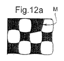
誤り防止マークMは、1以上のチャネルにわたって延在しうる。特に、誤り防止マークMは、50を超えない、30を超えない、20を超えない、10を超えない、または5をこえないチャネルにわたって、または単一チャネルにわたってさえ延在しうる。したがって、有利には、該マークは、濾過体を通るガスの流れおよび特に濾過体を通りぬけることによって引き起こされる圧力低下に、影響を与えないかまたは実質的に影響を与えない。 The error prevention mark M can extend over one or more channels. In particular, the error prevention mark M may extend over channels not exceeding 50, not exceeding 30, not exceeding 20, not exceeding 10, or not exceeding 5, or even a single channel. Thus, advantageously, the mark does not affect or substantially does not affect the flow of gas through the filter body and in particular the pressure drop caused by passing through the filter body.
誤り防止マークMは、周辺チャネルのグループから、隅チャネルのグループからおよび内部チャネルのグループから、排他的に選ばれた1以上のチャネルにわたって延在しうる。1実施態様においては、誤り防止マークは、周辺チャネルのグループから排他的に、または隅チャネルのグループから排他的に、選択された1以上のチャネルにわたって延在している。好ましくは、誤り防止マークは、単一の周辺チャネルまたは隅チャネルにわたって延在している。 The error prevention mark M may extend over one or more channels selected exclusively from a group of peripheral channels, from a group of corner channels and from a group of internal channels. In one embodiment, the error prevention mark extends over one or more selected channels exclusively from a group of peripheral channels or exclusively from a group of corner channels. Preferably, the error prevention mark extends over a single peripheral channel or corner channel.
もし誤り防止マークが1つの隅チャネル上に備えられるときは、単位濾過ブロックがこの隅の二等分線に対してそれ自身対称であるならば、誤り防止マークはこの隅の二等分線に対して対称であってはならない。このことが、示された実施態様(これは方形断面の単位濾過ブロックに関するものである)において、該誤り防止マークが隅チャネルになぜ備えられなかったかの理由である。 If when the error protection mark is provided on one corner channel, if the unit is filtered block is itself symmetrical with respect to the corner bisector, error protection mark the bisector of this corner It must not be symmetrical. This is, (which relates to units filtered block of rectangular cross-section) illustrated embodiment in a one of the reasons the error protection mark is not provided because the corner channel.
誤り防止マークMをハニカム構造の周辺部および特にこの構造の1の隅チャネルに置くことは、有利にこの構造の製作を容易にする。穴を塞ぐクサビまたはフレームは実際に、押し出し中に誤り防止マークを創るために押し出しダイス上に容易に配置されうる。 Placing the error prevention mark M in the periphery of the honeycomb structure and in particular in one corner channel of the structure advantageously facilitates the production of this structure. The wedge or frame that plugs the hole can actually be easily placed on the extrusion die to create an error prevention mark during extrusion.
図16aおよび16bは、本発明に従うハニカム構造の下流面を示している。このハニカム構造の外周は非対称であるので、確かにこの構造は誤り防止マークを有している。しかし、この誤り防止マークは10を超えるチャネルにわたって延在している。 Figures 16a and 16b show the downstream face of a honeycomb structure according to the present invention. Since the outer periphery of the honeycomb structure is asymmetric, this structure certainly has an error prevention mark. However, this error prevention mark extends over more than 10 channels.
対照的に、図17aおよび17bにおいては、誤り防止マークは10未満のチャネルにわたって延在している。これらの図においては、問題のチャネルは破線で囲まれている(囲みC)。 In contrast, in FIGS. 17a and 17b, the error prevention mark extends over less than 10 channels. In these figures, the channel in question is surrounded by a broken line (box C).
誤り防止マークは、1以上のチャネルの特別な形状から導かれうる。特に、それは特別なアスペクト比から、中でも、他のチャネルのアスペクト比の平均と少なくとも3%、少なくとも5%、少なくとも8%、または少なくとも12%は異なるアスペクト比から導かれうる。 Error prevention marks can be derived from the special shape of one or more channels. In particular, it may be derived from a particular aspect ratio, among which from an aspect ratio that differs from the average of the other channel aspect ratios by at least 3%, at least 5%, at least 8%, or at least 12%.
誤り防止マークは、1以上の入口開口部及び/又は出口開口部の特別な構成、例えば厚さの変化から、または特にこの若しくはこれらの開口部を狭くし若しくは広げることによるプリフォームの変形から導かれうる。 The error prevention mark is derived from a special configuration of one or more inlet openings and / or outlet openings, for example from a change in thickness, or in particular from deformation of the preform by narrowing or widening this or these openings. Can be.
好ましくは、誤り防止マークを創り出することは、問題の1チャネルまたは複数チャネルの開口部に追加の隅を創り出すことではない。それとは反対に、誤り防止マークは、問題の1チャネルまたは複数チャネルの開口部の隅を、例えばこの開口部を環状化することによって取り除くことから導かれうる。図6aおよび6bに示されるように、円形開口部または少なくとも部分的に丸められた端は、特に誤り防止マークを構成しうる。有利には自動車用濾過器のための応用においては、この構成は使用中に濾過体の受ける熱機械応力を変更しないまたは低減さえもしない。 Preferably, creating error prevention marks is not creating additional corners in the one or more channel openings in question. On the other hand, error prevention marks can be derived from removing the corners of the one or more channel openings in question, for example by circularizing the openings. As shown in FIGS. 6a and 6b, the circular opening or the at least partly rounded edge may in particular constitute an error-proof mark. Advantageously, in applications for automotive filters, this configuration does not change or even reduce the thermomechanical stress experienced by the filter during use.
1実施形態においては、誤り防止マークを形成するチャネルまたはチャネルの集合は、上流面及び/又は下流面で、それ以外のチャネルの平均壁厚と少なくとも10%、好ましくは少なくとも20%違う平均壁厚を有している。 In one embodiment, the channel or set of channels forming the error prevention mark has an average wall thickness that differs at least 10%, preferably at least 20% from the average wall thickness of the other channels on the upstream and / or downstream surfaces. have.
1実施形態においては、誤り防止マークを形成するチャネルまたはチャネルの集合は、上流面及び/又は下流面上に、それ以外のチャネルの平均開口部面積と少なくとも10%、好ましくは少なくとも20%、または少なくとも30%違う平均開口部面積を有している(図8aおよび8bを見よ)。 In one embodiment, the channel or set of channels forming the error prevention mark is on the upstream and / or downstream surface at least 10%, preferably at least 20% with the average opening area of the other channels, or Have an average opening area that differs by at least 30% (see FIGS. 8a and 8b).
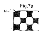
1実施形態においては、1チャネルの開口部の変形は、図8aおよび8bまたは図14aおよび14bのように、隣接チャネルの開口部の変形に対応している。断面が一定であるとき、2つ(上流および下流)のパターンは、誤り防止マークの提供によって影響される。同じことがハニカム構造の側壁上に備えられた誤り防止マークに対しても妥当する(図7aおよび7b)。 In one embodiment, the deformation of the opening of one channel corresponds to the deformation of the opening of the adjacent channel, as in FIGS. 8a and 8b or FIGS. 14a and 14b. When the cross section is constant, the two (upstream and downstream) patterns are affected by the provision of error prevention marks. The same is valid for the error prevention marks provided on the side walls of the honeycomb structure (FIGS. 7a and 7b).
誤り防止マークは、問題のチャネルに、材料を加えること(例えば図9aおよび9bを見よ)、例えば仕切りを追加することによって(図10aおよび10b)、または材料を取り除くことから導かれうる。 Error prevention marks can be derived from adding material to the channel in question (see, eg, FIGS. 9a and 9b), for example by adding dividers (FIGS. 10a and 10b), or from removing material.
誤り防止マークは、図7aおよび7bに示されるように、ハニカム構造の外周囲の変更からも導かれうる。しかし、誤り防止マークは、この周辺の変更から導かれない、または、その変更のみによっては導かれないことが好ましい。換言すれば、誤り防止マークは、ハニカム構造の側面(13)上に排他的には与えられない。
それ故に、もしこの側面が変更され、特に周辺コーティングまたは接合セメントを施与することによって変更されるときは、誤り防止マークは可視のままである。
The error prevention marks can also be derived from changes in the outer periphery of the honeycomb structure, as shown in FIGS. 7a and 7b. However, it is preferable that the error prevention mark is not derived from this peripheral change or only from the change. In other words, the error prevention mark is not given exclusively on the side surface (13) of the honeycomb structure.
Therefore, if this side is changed, especially when applied by applying a peripheral coating or cement, the error prevention mark remains visible.
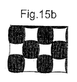
1実施形態においては、誤り防止マークを形成するチャネルまたはチャネルの集合は、上流面及び/又は下流面上に、これ以外のチャネルの外周囲及び/又は内周囲とは異なる外周囲及び/又は内周囲を有している。特に、チャネル、または誤り防止マークを形成するチャネルの集合の少なくとも1つのチャネルは、非対称性またはそれ以外のチャネルからそのチャネルを区別する形状を有している。図15aおよび15bは、ハニカム構造の方形断面のチャネルの形状で誤り防止マークを備える説明的な例、(ハニカム構造は波打つチャネルのみを備える)を示している。 In one embodiment, the channel or set of channels forming the error prevention mark is on the upstream and / or downstream surface, and the outer periphery and / or inner periphery different from the outer periphery and / or inner periphery of other channels. Has a perimeter. In particular, at least one channel of a channel or set of channels forming an error prevention mark has a shape that distinguishes the channel from asymmetry or other channels. FIGS. 15a and 15b show an illustrative example of a honeycomb structure with a square cross-sectional channel shape with error prevention marks (the honeycomb structure only comprises undulating channels).
勿論、ここで記載した様々な実施態様は、任意的に組合せられうる。
製作過程
Of course, the various embodiments described herein may be arbitrarily combined.
Production process
本発明に従うハニカム構造は、現在採用されている全ての技術によって製作されうる。 The honeycomb structure according to the present invention can be manufactured by all currently employed techniques.
1実施形態においては、ハニカムプリフォームは、押し出し後、特定の工程の間にマーク付けされる。例えば、プリフォームの1以上のチャネルは、局所的に押し潰され、締め付けられまたは大きくされうる。有利には、誤り防止マークの付加は、追加的な材料の消費を要しない。さらに、誤り防止マークは局所的でありえて、例えば1以上の入口チャネルの開口部にわたってのみ延在しうる。誤り防止マークをハニカム構造に付加するために、その全長にわたってハニカム構造を変更することは必要ではない。 In one embodiment, the honeycomb preform is marked during a specific process after extrusion. For example, one or more channels of the preform can be locally crushed, clamped or enlarged. Advantageously, the addition of error prevention marks does not require the consumption of additional materials. Furthermore, the error prevention mark can be local, for example extending only over the opening of one or more inlet channels. In order to add the error prevention mark to the honeycomb structure, it is not necessary to change the honeycomb structure over its entire length.
1実施形態においては、誤り防止マークは、プリフォームが焼結された後に、例えば、機械加工によって創り出される。特に、ハニカム構造の隅または縁を面取りすることが可能である。 In one embodiment, the error prevention mark is created, for example, by machining, after the preform has been sintered. In particular, it is possible to chamfer the corners or edges of the honeycomb structure.
好ましくは、上記の工程a)およびb)は、本発明に従う押し出しダイスを使って実行されうる。ハニカム構造は一定断面を有し、そして誤り防止マークは、プリフォームと同じ材料から作られる。有利には、このことはそれ故に、特定の成形道具を使わねばならないことを回避する。さらに、この過程は、製造過程において追加的な工程を必要とせず、このことは特にレーザー切除による模様付けを含む過程に関して特に有利である。さらにレーザー切除の技術は高価である。 Preferably, the above steps a) and b) can be carried out using an extrusion die according to the invention. The honeycomb structure has a constant cross section, and the error prevention mark is made from the same material as the preform. Advantageously, this therefore avoids having to use a specific molding tool. Furthermore, this process does not require any additional steps in the manufacturing process, which is particularly advantageous for processes involving laser ablation patterning. Furthermore, laser ablation techniques are expensive.
最後に、押し出しダイスは、押し出しの間に誤り防止マークを作るために、従来のダイスを使って、ダイスの下流に、穴を塞ぐフレームまたはクサビを置くことによって、有利に容易に製作されうる。 Finally, extrusion dies can be advantageously made easily by placing a frame or wedge closing the hole downstream of the dies using conventional dies to create error prevention marks during extrusion.
ステップa)およびb)は、従来のハニカム構造を製造するために通常実行される。これらのステップは、例えば、特許出願、欧州特許第816065、欧州特許第1142619、欧州特許第1455923、国際公開公報2004/090294または国際公開公報2005/063462に記載されている。焼結条件は使用された材料によって適合化せられる。 Steps a) and b) are usually carried out to produce a conventional honeycomb structure. These steps are described, for example, in patent application, European Patent No. 816065, European Patent No. 1142619, European Patent No. 1455923, International Publication No. 2004/090294 or International Publication No. 2005/066342. The sintering conditions are adapted according to the material used.
焼結温度は、好ましくは1300℃を超え、好ましくは1600℃を超え、好ましくは1800℃を超え及び/又は2400℃未満、好ましくは2350℃未満である。
濾過体への適用
The sintering temperature is preferably above 1300 ° C, preferably above 1600 ° C, preferably above 1800 ° C and / or below 2400 ° C, preferably below 2350 ° C.
Application to filter media
本発明に従うハニカム構造は、特に、一体型濾過体、または組み立てられた濾過体を形成するために組み立てられることが予定された濾過ブロック、を製造するのに有用である。 The honeycomb structure according to the present invention is particularly useful for manufacturing integral filter bodies or filter blocks that are intended to be assembled to form an assembled filter body.
この目的のために、特定チャネルの開口部は、入口チャネルを構成するために下流面上で閉塞されねばならず、そしてそれ以外のチャネルの開口部は、出口チャネルを構成するために上流面上で閉塞されねばならない。閉塞する操作は、閉塞されるべきチャネルの種類に従って、特にその断面またはその形状に依存して、過程を変更する必要がありうる。その結果、上流および下流面を識別できることが必要である。 For this purpose, the opening of a particular channel must be blocked on the downstream surface to constitute the inlet channel, and the other channel opening must be on the upstream surface to constitute the outlet channel. Must be occluded. The occluding operation may need to change process according to the type of channel to be occluded, especially depending on its cross-section or its shape. As a result, it is necessary to be able to distinguish upstream and downstream surfaces.
この識別は、入口チャネルの開口部が出口チャネルの開口部に似ているときは、困難でありうる。 This identification can be difficult when the inlet channel opening resembles the outlet channel opening.
濾過体の大量生産のための現代的過程においては、カメラがこの識別のために使われている。そのような識別器具は、しかしながら高価であり追加のステップを要する。 In modern processes for mass production of filter bodies, cameras are used for this identification. Such identification devices, however, are expensive and require additional steps.
さらに、もし入口チャネルの開口部形状と出口チャネルのそれとの間の違いが辛うじて認知可能であるときは、識別エラーが生じうる。 Furthermore, if the difference between the opening shape of the inlet channel and that of the outlet channel is barely perceptible, an identification error can occur.
最後に、押し出し工程の可変性は、識別エラーをも生み出しうるチャネルの形状における変化を導く。このような識別エラーは、チャネルの間違った開口部が閉塞されることを結果し、または低品質のプラグが製造されることになる。したがって濾過体はスクラップにされなければならない。本発明に従うハニカム構造の誤り防止マークは、したがって特に有用である。 Finally, the variability of the extrusion process leads to changes in the shape of the channel that can also create identification errors. Such identification errors can result in the wrong opening of the channel being blocked or a low quality plug can be produced. Therefore, the filter body must be scrapped. The error prevention mark of the honeycomb structure according to the present invention is therefore particularly useful.
1実施形態においては、ハニカム構造体の一部分は、例えば、一酸化炭素(CO)、HCまたはNOxタイプの汚染ガスの取り扱いに適合した触媒コーティングまたは洗浄被膜で被覆される。例えば、最適な性能のために、洗浄被膜は、チャネルの部分を規定する表面に対してのみ、例えば濾過体の入口チャネルを規定する表面にのみ施与されうる。洗浄被膜の施与の間に、ハニカム構造の面を識別することは、したがって必要である。本発明に従うハニカム構造は、この目的のためによく適合する。 In one embodiment, a portion of the honeycomb structure is coated with a catalyst coating or cleaning film adapted for handling, for example, carbon monoxide (CO), HC, or NOx type pollutant gases. For example, for optimum performance, the cleaning coating may be applied only to the surface defining the portion of the channel, for example only to the surface defining the inlet channel of the filter body. It is therefore necessary to identify the face of the honeycomb structure during application of the cleaning coating. The honeycomb structure according to the invention is well suited for this purpose.
濾過体が排気ライン上に搭載されねばならないとき、該濾過体は、濾過されるべき若しくは汚染制御されるべきガスの流れに対して、適切に配向されることもまた重要である。不適合な圧力低下または蓄積煤および残留物の不適合な体積のリスクはそれ故に制限させる。再生制御誤差および燃料の過剰消費のリスクもまた制限される。 When the filter body must be mounted on the exhaust line, it is also important that the filter body is properly oriented with respect to the gas flow to be filtered or pollution controlled. The risk of incompatible pressure drop or accumulation soot and incompatible volume of residue is therefore limited. The risk of regeneration control errors and excessive fuel consumption is also limited.
上で説明したように、誤り防止マークは、好ましくは、濾過体の外周囲の変更のみから導かれるのではない。それは、濾過体の側面にのみ施与されたマークと異なり、周辺コーティングをこの側面へ施与することによって消去されまたは見えなくされたりするリスクがない。 As explained above, the error prevention mark is preferably not derived solely from a change in the outer periphery of the filter body. It differs from marks applied only to the side of the filter body, without the risk of being erased or obscured by applying a peripheral coating to this side.
この特徴は、缶が排気ライン上に搭載される前に濾過体が缶内に置かれるときに、特にその缶が濾過体を通る排気ガスの流れの方向を識別出来うる指示物も持たないときに、また有利である。 This feature is useful when the filter is placed in the can before it is mounted on the exhaust line, especially when the can has no indication that can identify the direction of the exhaust gas flow through the filter. Also advantageous.
本発明に従う濾過体の誤り防止マークは、それ故に、洗浄被覆、周辺コーティングまたは缶による濾過体の側面のマーク付けを有利に許容する。誤り防止マークはそれ故に、下流面から上流面を識別するための信頼しうる手段を構成する。 The error prevention mark of the filter according to the invention therefore advantageously allows the side of the filter to be marked with a cleaning coating, a peripheral coating or a can. The error prevention mark therefore constitutes a reliable means for distinguishing the upstream surface from the downstream surface.
本発明に従うハニカム構造は、組み立てられた濾過体の製造を行うという場合には、また特定の優位性を有している。 The honeycomb structure according to the invention also has a particular advantage when producing an assembled filter body.
好ましくは、誤り防止マークは、組み立てられた濾過体の単位濾過ブロックの外周囲を変更することからだけでは、生じるのではない。したがって、接合セメントの施与による組み立て作業の間にマスクされるリスクはない。単位濾過ブロックを接合している間、単位濾過ブロックの全ての入口面は、同じ側に置かれねばならない。誤り防止マークは、位置決め誤差のリスクを効率的に減らすことを可能にする。 Preferably, the error prevention mark does not arise from only changing the outer perimeter of the unit filter block of the assembled filter body. Therefore, there is no risk of being masked during the assembly operation due to the application of bonding cement. While joining the unit filter blocks, all inlet faces of the unit filter blocks must be on the same side. Error protection mark makes it possible to reduce the risk of positioning errors efficiently.
1実施形態においては、誤り防止マークは、ハニカム構造の特定の領域、例えば単位濾過ブロックの1以上の面が識別されるのをまた許すようにデザインされる。この実施態様は、単位濾過ブロックが長手方向に沿うのではなく、それ以外の他の方向に沿うように向けられねばならないとき、特に有用である。何故なら、例えば、単位濾過ブロックの1の特定の側面が、他の単位濾過ブロックの別の特定の側面へ接合されるために識別されねばならないからであり、また、接合されるべき単位濾過ブロックの側面の領域のみを区別する必要があるためだからである。この実施態様においては、誤り防止マークは、長手方向軸の周りの角度位置が識別されることを可能にする。 In one embodiment, the error prevention mark is designed to also allow a particular region of the honeycomb structure, eg, one or more faces of the unit filtration block to be identified. This embodiment is particularly useful when the unit filtration block must be oriented along other directions, rather than along the longitudinal direction. This is because, for example, one particular side of a unit filtration block must be identified in order to be joined to another particular side of another unit filtration block, and the unit filtration block to be joined. This is because it is necessary to distinguish only the area of the side. In this embodiment, the error prevention mark allows the angular position about the longitudinal axis to be identified.
好ましくは、単位濾過ブロックの組み立ての間、チャネルが接合セメントによって閉塞されることを防止するために、一方それでも誤り防止マークは観察されうるために、透明なマスクがこれらのブロックの上流および下流面へ施与される。 Preferably, during the assembly of the unit filtration blocks, transparent masks are provided on the upstream and downstream surfaces of these blocks in order to prevent the channels from being blocked by the joining cement, while still allowing error-proof marks to be observed. Applied to.
今や明確に明らかなように、本発明に従うハニカム構造は、誤り防止マークを有しており、該誤り防止マークは、濾過体への適用においては、使用にあたって消えることはない。外部での洗浄作業、特に部分的または完璧に残留灰を除去するための作業およびリサイクル作業はこの誤り防止マークによって容易にされる。 Now As clearly apparent, the honeycomb structure according to the present invention has error protection mark, the error protection mark, in the application to the filter body, does not disappear when used. External cleaning operations, in particular, operations for removing residual ash partially or completely and recycling operations are facilitated by this error prevention mark.
さらに、好ましい実施態様においては、濾過体の側面への接合セメントのまたは周辺コーティングの施与の場合に、または濾過体の缶との一体化、特に自動車の排気ライン上に搭載される場合にも、誤り防止マークは見え続ける。 Furthermore, in a preferred embodiment, when applying cement or peripheral coatings to the sides of the filter body, or when integrated with the filter can, especially when mounted on the exhaust line of an automobile. The error prevention mark continues to be visible.
勿論、本発明は、例として記載されかつ与えられた実施態様に限定されない。特に、チャネルは必ずしも方形断面をもつ必要はない。 Of course, the invention is not limited to the embodiments described by way of example and given. In particular, the channel does not necessarily have a square cross section.
別の実施態様においては、隣接する入口チャネルおよび出口チャネルは、任意の1の入口チャネルによって濾過されたガスの全てが、上記入口チャネルに隣接する出口チャネルを通過するように、お互いに対して配列されない。 In another embodiment, adjacent inlet and outlet channels are arranged relative to each other such that all of the gas filtered by any one inlet channel passes through the outlet channel adjacent to the inlet channel. Not.
1 微粒子濾過器
3 一般的な(円柱状)濾過体
5 金属缶
11 単位濾過ブロック
12 継ぎ手
13 ハニカム構造の側面
14 プリフォームの側面(側壁)
18 隣接チャネル
18e 入口チャネル
18s 出口チャネル
18i 内側チャネル
18p 周辺チャネル
18p’ 側方チャネル
18p” 隅チャネル
22 隣接チャネルの側壁
24e 上流開口部
24s 下流開口部
26e 上流面
26s 下流面
30s 上流プラグ
30e 下流プラグ
DESCRIPTION OF
13 Side surface of honeycomb structure 14 Side surface of preform (side wall)
18
Claims (15)
該上流面および下流面の少なくとも1つは、50未満のチャネルにわたり延在しかつ上流および下流パターンのいずれかが他方の上に完全に重ね合わされることを不可能にする誤り防止マーク(M)を有しており、該上流及び/又は下流パターンの外周囲は対称であるかまたは10未満のチャネルにわたり延在する非対称性を持っていることを特徴とする、ハニカム構造。 A honeycomb structure (3; 11) having a set of a plurality of adjacent channels, each channel having an upstream opening (32e) and a downstream opening (32s) on an upstream surface (26e) and a downstream surface (26s), respectively. In which the set of channels form an upstream pattern and a downstream pattern on the upstream surface and the downstream surface, respectively,
At least one of the upstream and downstream surfaces extends over less than 50 channels and prevents any of the upstream and downstream patterns from being completely superimposed on the other (M) A honeycomb structure characterized in that the outer perimeter of the upstream and / or downstream pattern is symmetric or has an asymmetry extending over less than 10 channels.
それ以外のチャネルのアスペクト比の平均から少なくとも5%違うアスペクト比、及び/又は、
該上流及び/又は下流面で、それ以外のチャネルの平均壁厚から少なくとも10%違う平均壁厚、及び/又は、
該上流及び/又は下流面で、それ以外のチャネルの平均開口部面積と少なくとも10%違う平均開口部面積、及び/又は、
該上流及び/又は下流面で、区別しうる非対称性
を有している、請求項1〜5のいずれか1項に記載のハニカム構造。 The channel or channels forming the error prevention mark are:
An aspect ratio that differs by at least 5% from the average aspect ratio of the other channels, and / or
An average wall thickness that differs by at least 10% from the average wall thickness of the other channels at the upstream and / or downstream surface, and / or
An average opening area at least 10% different from the average opening area of the other channels at the upstream and / or downstream surface, and / or
The honeycomb structure according to any one of claims 1 to 5, wherein the honeycomb structure has a distinguishable asymmetry on the upstream and / or downstream surface.
該第1チャネルの累積総容積Veの該第2チャネルの累積総容積Vsに対する比rは、1.03より大きく、しかし3未満である、及び/又は、
該第1チャネルの累積総内部面積の該第2チャネルの累積内部面積に対する比r’は、1.03より大きく、しかし3未満である、請求項1〜9のいずれか1項に記載のハニカム構造。 The first and second adjacent channels are alternately arranged so as to form a checkered pattern in cross section in a partially overlapped set like a roof tile,
The ratio r of the cumulative total volume Ve of the first channel to the cumulative total volume Vs of the second channel is greater than 1.03 but less than 3 and / or
The honeycomb according to any one of the preceding claims, wherein the ratio r 'of the cumulative total internal area of the first channel to the cumulative internal area of the second channel is greater than 1.03 but less than 3. Construction.
前記ハニカム構造の該チャネルを閉塞する方法、
部分的にまたは完全に残留灰を除去するように前記ハニカム構造を清掃する方法、
前記ハニカム構造に触媒コーティングを施与する方法、
周辺コーティング、特に排気ガスに対して非透過性の断熱コーティングセメントで作られた周辺コーティングを施与する方法、
自動車の排気ラインにまたはそのような排気ラインのために予定された濾過体のケーシングに、前記ハニカム構造を備える濾過体を搭載する方法、
複数の単位濾過ブロックを組み立てる方法、ここで前記単位濾過ブロックの少なくとも1つは、組み立てられた濾過体を構成するように、前記ハニカム構造を備えている、
から選択され、
入口及び/又は出口面は、該ハニカム構造上の誤り防止マークを観察することおよび前記識別に従い前記ハニカム構造の位置決めを行うことによって識別される、前記方法。 A method comprising the step of determining the position of the honeycomb structure according to any one of claims 1 to 13, wherein the method closes the channel of the honeycomb structure,
A method of cleaning the honeycomb structure to remove residual ash partially or completely;
A method of applying a catalyst coating to the honeycomb structure;
A method of applying a peripheral coating, in particular a peripheral coating made of a thermal barrier coating cement that is impermeable to exhaust gases
A method of mounting a filter body with said honeycomb structure in an exhaust line of a motor vehicle or in a casing of a filter body intended for such an exhaust line;
A method of assembling a plurality of unit filtration blocks, wherein at least one of the unit filtration blocks includes the honeycomb structure so as to constitute an assembled filter body.
Selected from
The method, wherein the inlet and / or outlet surfaces are identified by observing error prevention marks on the honeycomb structure and positioning the honeycomb structure according to the identification.
Applications Claiming Priority (3)
| Application Number | Priority Date | Filing Date | Title |
|---|---|---|---|
| FR0954791A FR2947735B1 (en) | 2009-07-09 | 2009-07-09 | HONEYCOMB STRUCTURE MARQUEE |
| FR0954791 | 2009-07-09 | ||
| PCT/IB2010/053160 WO2011004351A1 (en) | 2009-07-09 | 2010-07-09 | Marked honeycomb structure |
Publications (3)
| Publication Number | Publication Date |
|---|---|
| JP2012532742A JP2012532742A (en) | 2012-12-20 |
| JP2012532742A5 JP2012532742A5 (en) | 2013-07-25 |
| JP5484571B2 true JP5484571B2 (en) | 2014-05-07 |
Family
ID=41716321
Family Applications (1)
| Application Number | Title | Priority Date | Filing Date |
|---|---|---|---|
| JP2012519113A Expired - Fee Related JP5484571B2 (en) | 2009-07-09 | 2010-07-09 | Marked honeycomb structure |
Country Status (5)
| Country | Link |
|---|---|
| US (1) | US8557011B2 (en) |
| EP (1) | EP2451557B1 (en) |
| JP (1) | JP5484571B2 (en) |
| FR (1) | FR2947735B1 (en) |
| WO (1) | WO2011004351A1 (en) |
Families Citing this family (7)
| Publication number | Priority date | Publication date | Assignee | Title |
|---|---|---|---|---|
| WO2014054159A1 (en) * | 2012-10-04 | 2014-04-10 | イビデン株式会社 | Honeycomb filter |
| US9072997B2 (en) * | 2012-11-30 | 2015-07-07 | Corning Incorporated | Substrate with sinuous web and particulate filter incorporating the same |
| JP6239303B2 (en) | 2013-07-31 | 2017-11-29 | イビデン株式会社 | Honeycomb filter |
| GB2520776A (en) * | 2013-12-02 | 2015-06-03 | Johnson Matthey Plc | Wall-flow filter comprising catalytic washcoat |
| GB2545747A (en) * | 2015-12-24 | 2017-06-28 | Johnson Matthey Plc | Gasoline particulate filter |
| US11268413B2 (en) * | 2019-05-07 | 2022-03-08 | Ford Global Technologies, Llc | Method and system for gasoline particulate filter |
| KR102588287B1 (en) * | 2021-01-25 | 2023-10-13 | 한국기계연구원 | Filter unit and filter system having the same |
Family Cites Families (14)
| Publication number | Priority date | Publication date | Assignee | Title |
|---|---|---|---|---|
| US3853485A (en) * | 1972-12-11 | 1974-12-10 | Corning Glass Works | Core member for catalytic oxidation converter |
| US4420316A (en) * | 1982-02-22 | 1983-12-13 | Corning Glass Works | Filter apparatus and method of making it |
| JPH084749B2 (en) * | 1985-01-21 | 1996-01-24 | 日本碍子株式会社 | Ceramic honeycomb structure |
| EP1382445B1 (en) | 1996-01-12 | 2013-04-24 | Ibiden Co., Ltd. | A method of manufacturing a filter for purifying exhaust gas |
| EP1508358B1 (en) | 1999-09-29 | 2009-04-15 | Ibiden Co., Ltd. | Honeycomb filter and ceramic filter assembly |
| JP4408183B2 (en) * | 2001-03-16 | 2010-02-03 | 日本碍子株式会社 | Honeycomb filter for exhaust gas purification |
| FR2833857B1 (en) | 2001-12-20 | 2004-10-15 | Saint Gobain Ct Recherches | FILTER BODY COMPRISING A PLURALITY OF FILTER BLOCKS, IN PARTICULAR FOR A PARTICLE FILTER |
| WO2003082467A1 (en) * | 2002-03-28 | 2003-10-09 | Ngk Insulators, Ltd. | Cell structural body, method of manufacturing cell structural body, and catalyst structural body |
| DE10238770A1 (en) * | 2002-08-23 | 2004-03-11 | Umicore Ag & Co.Kg | Device for removing soot particles from the exhaust gas of a diesel engine |
| FR2853256B1 (en) | 2003-04-01 | 2005-10-21 | Saint Gobain Ct Recherches | FILTRATION STRUCTURE, PARTICULARLY PARTICLE FILTER FOR THE EXHAUST GASES OF AN INTERNAL COMBUSTION ENGINE. |
| FR2864576B1 (en) | 2003-12-24 | 2006-03-03 | Saint Gobain Ct Recherches | BLOCK FOR FILTRATION OF PARTICLES CONTAINED IN THE EXHAUST GASES OF AN INTERNAL COMBUSTION ENGINE |
| FR2874647B1 (en) * | 2004-08-25 | 2009-04-10 | Saint Gobain Ct Recherches | FILTER PACK WITH FINS FOR FILTRATION OF PARTICLES CONTAINED IN THE EXHAUST GASES OF AN INTERNAL COMBUSTION ENGINE |
| US20090166910A1 (en) * | 2005-11-16 | 2009-07-02 | Geo2 Technologies, Inc. | System and Method for Twin Screw Extrusion of a Fibrous Porous Substrate |
| SE532906C2 (en) * | 2008-09-23 | 2010-05-04 | Scania Cv Abp | Hydrolysis catalyst with greater channel cross-section in the peripheral part than in the central part and methods for hydrolysis of a urea |
-
2009
- 2009-07-09 FR FR0954791A patent/FR2947735B1/en not_active Expired - Fee Related
-
2010
- 2010-07-09 EP EP10740357.8A patent/EP2451557B1/en not_active Not-in-force
- 2010-07-09 WO PCT/IB2010/053160 patent/WO2011004351A1/en active Application Filing
- 2010-07-09 US US13/382,969 patent/US8557011B2/en not_active Expired - Fee Related
- 2010-07-09 JP JP2012519113A patent/JP5484571B2/en not_active Expired - Fee Related
Also Published As
| Publication number | Publication date |
|---|---|
| FR2947735A1 (en) | 2011-01-14 |
| US8557011B2 (en) | 2013-10-15 |
| FR2947735B1 (en) | 2011-08-12 |
| EP2451557A1 (en) | 2012-05-16 |
| EP2451557B1 (en) | 2013-04-17 |
| US20120125468A1 (en) | 2012-05-24 |
| JP2012532742A (en) | 2012-12-20 |
| WO2011004351A1 (en) | 2011-01-13 |
Similar Documents
| Publication | Publication Date | Title |
|---|---|---|
| JP5484571B2 (en) | Marked honeycomb structure | |
| JP2012532742A5 (en) | ||
| KR100607478B1 (en) | Honeycomb filter | |
| US7138002B2 (en) | Honeycomb structure and process for production thereof | |
| JP4727902B2 (en) | Honeycomb particulate filter | |
| EP1580181B1 (en) | Honeycomb structure and method of manufacturing the same | |
| EP1470852B1 (en) | Honeycomb structure and method of manufacturing the same | |
| JPWO2008120499A1 (en) | Honeycomb segment | |
| JP4431576B2 (en) | Filtration unit for filtering particles contained in exhaust gas from internal combustion engine | |
| CN103458991A (en) | Sealed honeycomb structure, and exhaust gas purification device | |
| EP2130574B1 (en) | Honeycomb filter | |
| JP4249489B2 (en) | Filter body for filtering particles contained in exhaust gas of internal combustion engine | |
| CN103458989A (en) | Sealed honeycomb structure | |
| CN102933279A (en) | Ceramic honeycomb structures | |
| JP6887303B2 (en) | Honeycomb filter | |
| JP4571633B2 (en) | Block for filtering particles contained in exhaust gas from internal combustion engine | |
| US7905939B2 (en) | Block for filtering particles contained in exhaust gases of an internal combustion engine | |
| JP6802075B2 (en) | Honeycomb structure | |
| CN101517205B (en) | Filter element, in particular for filtering exhaust gases of an internal combustion engine | |
| JPWO2008126433A1 (en) | Honeycomb segment and honeycomb structure | |
| JP6887301B2 (en) | Honeycomb filter | |
| JP2018192386A (en) | Honeycomb filter | |
| JP6041476B2 (en) | Honeycomb structure | |
| JP2009101344A (en) | Exhaust gas cleaning filter and method for manufacturing the same | |
| JP6887302B2 (en) | Honeycomb filter |
Legal Events
| Date | Code | Title | Description |
|---|---|---|---|
| A521 | Request for written amendment filed |
Free format text: JAPANESE INTERMEDIATE CODE: A523 Effective date: 20130603 |
|
| A621 | Written request for application examination |
Free format text: JAPANESE INTERMEDIATE CODE: A621 Effective date: 20130603 |
|
| A977 | Report on retrieval |
Free format text: JAPANESE INTERMEDIATE CODE: A971007 Effective date: 20131225 |
|
| TRDD | Decision of grant or rejection written | ||
| A01 | Written decision to grant a patent or to grant a registration (utility model) |
Free format text: JAPANESE INTERMEDIATE CODE: A01 Effective date: 20140124 |
|
| A61 | First payment of annual fees (during grant procedure) |
Free format text: JAPANESE INTERMEDIATE CODE: A61 Effective date: 20140218 |
|
| R150 | Certificate of patent or registration of utility model |
Ref document number: 5484571 Country of ref document: JP Free format text: JAPANESE INTERMEDIATE CODE: R150 |
|
| LAPS | Cancellation because of no payment of annual fees |