JP5483954B2 - Mobile drive unit - Google Patents
Mobile drive unit Download PDFInfo
- Publication number
- JP5483954B2 JP5483954B2 JP2009189519A JP2009189519A JP5483954B2 JP 5483954 B2 JP5483954 B2 JP 5483954B2 JP 2009189519 A JP2009189519 A JP 2009189519A JP 2009189519 A JP2009189519 A JP 2009189519A JP 5483954 B2 JP5483954 B2 JP 5483954B2
- Authority
- JP
- Japan
- Prior art keywords
- time
- moving body
- light emitting
- motor
- passed
- Prior art date
- Legal status (The legal status is an assumption and is not a legal conclusion. Google has not performed a legal analysis and makes no representation as to the accuracy of the status listed.)
- Expired - Fee Related
Links
Images


Classifications
-
- G—PHYSICS
- G03—PHOTOGRAPHY; CINEMATOGRAPHY; ANALOGOUS TECHNIQUES USING WAVES OTHER THAN OPTICAL WAVES; ELECTROGRAPHY; HOLOGRAPHY
- G03B—APPARATUS OR ARRANGEMENTS FOR TAKING PHOTOGRAPHS OR FOR PROJECTING OR VIEWING THEM; APPARATUS OR ARRANGEMENTS EMPLOYING ANALOGOUS TECHNIQUES USING WAVES OTHER THAN OPTICAL WAVES; ACCESSORIES THEREFOR
- G03B15/00—Special procedures for taking photographs; Apparatus therefor
- G03B15/02—Illuminating scene
- G03B15/03—Combinations of cameras with lighting apparatus; Flash units
- G03B15/05—Combinations of cameras with electronic flash apparatus; Electronic flash units
-
- G—PHYSICS
- G03—PHOTOGRAPHY; CINEMATOGRAPHY; ANALOGOUS TECHNIQUES USING WAVES OTHER THAN OPTICAL WAVES; ELECTROGRAPHY; HOLOGRAPHY
- G03B—APPARATUS OR ARRANGEMENTS FOR TAKING PHOTOGRAPHS OR FOR PROJECTING OR VIEWING THEM; APPARATUS OR ARRANGEMENTS EMPLOYING ANALOGOUS TECHNIQUES USING WAVES OTHER THAN OPTICAL WAVES; ACCESSORIES THEREFOR
- G03B2215/00—Special procedures for taking photographs; Apparatus therefor
- G03B2215/05—Combinations of cameras with electronic flash units
- G03B2215/0503—Built-in units
- G03B2215/0507—Pop-up mechanisms
-
- G—PHYSICS
- G03—PHOTOGRAPHY; CINEMATOGRAPHY; ANALOGOUS TECHNIQUES USING WAVES OTHER THAN OPTICAL WAVES; ELECTROGRAPHY; HOLOGRAPHY
- G03B—APPARATUS OR ARRANGEMENTS FOR TAKING PHOTOGRAPHS OR FOR PROJECTING OR VIEWING THEM; APPARATUS OR ARRANGEMENTS EMPLOYING ANALOGOUS TECHNIQUES USING WAVES OTHER THAN OPTICAL WAVES; ACCESSORIES THEREFOR
- G03B2215/00—Special procedures for taking photographs; Apparatus therefor
- G03B2215/05—Combinations of cameras with electronic flash units
- G03B2215/0564—Combinations of cameras with electronic flash units characterised by the type of light source
- G03B2215/0578—Flashtube mounting
-
- G—PHYSICS
- G03—PHOTOGRAPHY; CINEMATOGRAPHY; ANALOGOUS TECHNIQUES USING WAVES OTHER THAN OPTICAL WAVES; ELECTROGRAPHY; HOLOGRAPHY
- G03B—APPARATUS OR ARRANGEMENTS FOR TAKING PHOTOGRAPHS OR FOR PROJECTING OR VIEWING THEM; APPARATUS OR ARRANGEMENTS EMPLOYING ANALOGOUS TECHNIQUES USING WAVES OTHER THAN OPTICAL WAVES; ACCESSORIES THEREFOR
- G03B2215/00—Special procedures for taking photographs; Apparatus therefor
- G03B2215/05—Combinations of cameras with electronic flash units
- G03B2215/0582—Reflectors
-
- G—PHYSICS
- G03—PHOTOGRAPHY; CINEMATOGRAPHY; ANALOGOUS TECHNIQUES USING WAVES OTHER THAN OPTICAL WAVES; ELECTROGRAPHY; HOLOGRAPHY
- G03B—APPARATUS OR ARRANGEMENTS FOR TAKING PHOTOGRAPHS OR FOR PROJECTING OR VIEWING THEM; APPARATUS OR ARRANGEMENTS EMPLOYING ANALOGOUS TECHNIQUES USING WAVES OTHER THAN OPTICAL WAVES; ACCESSORIES THEREFOR
- G03B2215/00—Special procedures for taking photographs; Apparatus therefor
- G03B2215/05—Combinations of cameras with electronic flash units
- G03B2215/0589—Diffusors, filters or refraction means
- G03B2215/0592—Diffusors, filters or refraction means installed in front of light emitter
Landscapes
- Physics & Mathematics (AREA)
- General Physics & Mathematics (AREA)
- Stroboscope Apparatuses (AREA)
- Control Of Position Or Direction (AREA)
- Studio Devices (AREA)
Description
本発明は、移動体駆動装置に関するものである。 The present invention relates to a moving body driving apparatus.
従来、移動体を駆動させる移動体駆動装置は、移動体が移動している位置を位置検出スイッチ等で検出することにより、移動体を停止する制御を行っていた。
例えば、特許文献1には、移動体としてのストロボ発光部を備えた移動体駆動装置としてのフラッシュカメラが開示されている。このカメラには、ストロボ発光部を移動可能に駆動するモータと、移動するストロボ発光部の位置を検出するスイッチとが備えられている。モータは、被写界の輝度に応じてストロボ発光部を発光位置まで移動させる。また、スイッチは、ストロボ発光部の駆動と停止とのタイミングを検出している。
Conventionally, a moving body drive device that drives a moving body performs control to stop the moving body by detecting a position where the moving body is moving with a position detection switch or the like.
For example, Patent Document 1 discloses a flash camera as a moving body driving device including a strobe light emitting unit as a moving body. This camera is provided with a motor that movably drives the strobe light emitting unit and a switch that detects the position of the strobe light emitting unit that moves. The motor moves the strobe light emitting unit to the light emitting position according to the luminance of the object scene. Further, the switch detects the timing of driving and stopping the strobe light emitting unit.
しかしながら、上述の特許文献1に開示されたカメラでは、モータの駆動電圧を常に一定に制御していて、スイッチから信号の有無に応じてモータの駆動および停止を制御している。このようなカメラでは、温度や湿度等のカメラの環境変化によりモータの駆動時の負荷が変わった場合、ストロボ発光部の駆動速度が不安定になってしまうという問題がある。例えば、周囲温度が低い場合、ストロボ発光部に接続されているリード線が硬くなってしまうため、ストロボ発光部の駆動速度が遅くなってしまうことが考えられる。 However, in the camera disclosed in Patent Document 1 described above, the drive voltage of the motor is always controlled to be constant, and the drive and stop of the motor are controlled according to the presence / absence of a signal from the switch. In such a camera, there is a problem that the driving speed of the strobe light emitting unit becomes unstable when the load during driving of the motor changes due to changes in the camera environment such as temperature and humidity. For example, when the ambient temperature is low, the lead wire connected to the strobe light emitting unit becomes hard, so the driving speed of the strobe light emitting unit may be slow.
本発明は、上述したような問題点に鑑みてなされたものであり、駆動負荷の変化に関わらず移動体を安定して駆動することを目的とする。 The present invention has been made in view of the above-described problems, and an object of the present invention is to stably drive a moving body regardless of changes in driving load.
本発明は、モータによって移動体を駆動する移動体駆動装置であって、前記移動体が第1の位置を通過したことを検出する第1の検出手段と、前記第1の検出手段によって前記移動体が前記第1の位置を通過したことを検出した後に、前記移動体が第2の位置を通過したことを検出する第2の検出手段と、前記第1の検出手段によって前記移動体が前記第1の位置を通過したことを検出した後であって、前記第2の検出手段によって前記移動体が前記第2の位置を通過したことを検出する前に、前記移動体が第3の位置を通過したことを検出する第3の検出手段と、前記第1の検出手段によって前記移動体が前記第1の位置を通過したことを検出してから、前記第2の検出手段によって前記移動体が前記第2の位置を通過したことを検出するまでの時間を計測する第1の計測手段と、前記第3の検出手段によって前記移動体が前記第3の位置を通過したことを検出してから、前記第2の検出手段によって前記移動体が前記第2の位置を通過したことを検出するまでの時間を計測する第2の計測手段と、前記第1の計測手段によって計測された時間に基づいて、前記移動体が前記第2の位置を通過したことを検出してから前記モータにブレーキをかけるまでの時間を設定し、前記第2の計測手段によって計測された時間に基づいて、前記移動体が前記第2の位置を通過したことを検出してから前記モータにブレーキをかけるまでの間に前記モータに供給する通電量を設定する設定手段と、を有することを特徴とする。 The present invention is a moving body drive device that drives a moving body by a motor, the first detecting means for detecting that the moving body has passed a first position, and the movement by the first detecting means. A second detecting means for detecting that the moving body has passed the second position after detecting that the body has passed the first position; and the first detecting means causes the moving body to be After detecting that the moving body has passed the first position, and before detecting that the moving body has passed the second position by the second detecting means, the moving body is moved to the third position. A third detecting means for detecting that the vehicle has passed, and the first detecting means for detecting that the moving body has passed the first position, and then the second detecting means for detecting the moving body. Detects that has passed the second position A first measuring means for measuring a time in, after detecting that the moving body has passed through the third position by the third detecting means, said movable body by said second detection means Based on the second measuring means for measuring the time until it is detected that the second position has been passed, and the time measured by the first measuring means, the moving body calculates the second position. The time from when the passage is detected until the brake is applied to the motor is set , and based on the time measured by the second measurement means, the fact that the moving body has passed the second position It characterized by having a setting means for setting the current amount to be supplied to the motor during the period from the detection to up braking to the motor.
本発明によれば、駆動負荷の変化に関わらず移動体を安定して駆動することができる。 According to the present invention, it is possible to stably drive a moving body regardless of changes in driving load.
以下に、本発明に係る実施形態について図面に基づいて詳細に説明する。
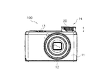
まず、図1を参照して、本実施形態に係る閃光発光装置を搭載した撮像装置について説明する。ここでは、撮像装置として例えばデジタルスチルカメラ(以下、カメラという)を取り上げて説明する。図1は、カメラの外観正面図である。
図1に示すように、カメラ100は、外装部材11、鏡筒部12、レリーズボタン13、閃光発光装置14等を含んで構成されている。外装部材11内には、図示しないCCDやCMOS等の撮像素子が収容されている。ユーザが、レリーズボタン13を押下することで撮影が行われ、鏡筒部12内に構成される図示しないレンズを透過した光学像が撮像素子に取り込まれ所定の撮像処理等が行われた後、画像データとして記録される。
また、夜間や暗所で撮影を行う場合、自動的またはユーザの操作に応じて、閃光発光装置14の発光部20が閃光を発光して撮影の補助をする。
Embodiments according to the present invention will be described below in detail with reference to the drawings.
First, with reference to FIG. 1, an imaging apparatus equipped with the flash light emitting device according to the present embodiment will be described. Here, for example, a digital still camera (hereinafter referred to as a camera) will be described as an imaging apparatus. FIG. 1 is an external front view of the camera.
As shown in FIG. 1, the
Further, when shooting at night or in a dark place, the
本実施形態のカメラ100は、発光部20を必要に応じて、カメラ本体である外装部材11内に収容したり、外装部材11外に露出させたりすることができるように構成されている。具体的に、発光部20は、図1に示す矢印方向、すなわち鉛直方向に移動可能である。ここで、図1に示す閃光発光装置14の発光部20は、外装部材11外に露出された状態(発光位置)である。一方、閃光発光装置14の発光部20が収容された場合、発光部20の上面とカメラ100の上面とが一致する状態(収納位置)になる。
The
次に、図2を参照して、閃光発光装置14の構成について説明する。図2は、閃光発光装置14を分解した斜視図である。閃光発光装置14は、複数の構成部品からなり、組み立てられることで一つのユニットとして構成される。
まず、閃光発光装置14の発光部20について、説明する。発光部20は、キセノン管21、反射笠22、プリズムパネル23、ベース部材24、カバー部材25等を含んでいる。
キセノン管21は、発光源であって、後述するリード線によって、アノードとカソードとに電気的に接続され、カメラ本体に配置される回路基板である図2に示すフレキシブル配線基板45に接続されている。また、キセノン管21の両側には、キセノン管ゴム21aが設けられている。キセノン管ゴム21aは、キセノン管21の端子部の絶縁およびキセノン管21を反射笠22に付勢する機能を有している。
Next, the configuration of the flash
First, the
The
反射笠22は、キセノン管21からの光を集光する。プリズムパネル23は、キセノン管21および反射笠22からの光を所望の撮影範囲で照射するように、入射面および射出面を備えている。ベース部材24は、上述したキセノン管21、反射笠22およびプリズムパネル23等の発光関連部品を組み込むことができる空間を有している。また、ベース部材24の下側には、後述する第5のギアと噛み合うラックギア24aが一体に形成されている。カバー部材25は、庇部25aを有していて、上面がカメラ100の外観を構成する。
The
なお、発光部20を組み立てる場合、ベース部材24に上述した発光関連部品を組み込み、カバー部材25を上方からベース部材24に対して嵌め合わせる。その後、図示しない引っ掛け部とビス26とを用いて、ベース部材24とカバー部材25とを固定させることで、ユニット化された発光部20を組み立てることができる。発光部20は、後述する駆動部30によって鉛直方向に沿って摺動し、発光位置および収納位置に移動することができる。
When assembling the
また、閃光発光装置14は、アウターカバー31が備えられている。
アウターカバー31は、カメラ100の外装部材11内に装着可能であって、上述した発光部20を鉛直方向に摺動可能に保持する保持部として機能する。アウターカバー31の下側には、キセノン管21等に電力を供給するコンデンサ41を保持するためのコンデンサ保持部31aが形成されている。さらに、アウターカバー31の側方には、発光部20からフレキシブル配線基板45に配線される後述するリード線に近接した位置であり、リード線に側方からアクセスできる開口部31bが形成されている。なお、アウターカバー31が、外装部材11内に装着された場合、開口部31bは外装部材11に囲まれて外部から閉塞された状態になる。
Further, the flash
The
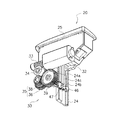
また、閃光発光装置14は、駆動部30が備えられている。ここで、図2および図3を参照して、閃光発光装置14の駆動部30について説明する。図3は、発光部20と駆動部30の一部との位置関係を後方下側から見た斜視図である。駆動部30は、モータ32、第1のギア33、第2のギア34、クラッチ付ギア35、第5のギア39、ギアホルダ40等を含んでいる。
モータ32は、発光部20を鉛直方向に駆動するための駆動源であり、例えばDCモータが用いられている。モータ32は、出力軸が水平方向に配設されるようにして、アウターカバー31の後方にネジ42を介して固定される。このモータ32の端子部への通電によって、モータ32の出力軸が正転方向または逆転方向に回転する。
次に伝達機構としての第1のギア33、第2のギア34、クラッチ付ギア35、第5のギア39について説明する。
まず、第1のギア33は、ウォームギアである。第1のギア33は、モータ32の出力軸に圧入され、モータ32の出力軸と同期して回転する。第2のギア34は、2段ギアである。第2のギア34の片段のギアは、第1ギア33と噛み合うウォームホイールを構成している。
The flash
The
Next, the
First, the
クラッチ付ギア35は、第3のギア36、クラッチスプリング37、第4のギア38を含んで構成されている。第3のギア36は、上述した第2ギア34と噛み合う。また、第4のギア38は、第5のギア39と噛み合う。
ここで、図4(a)および図4(b)を参照して、クラッチ付ギア35の構成について詳細に説明する。図4(a)は、クラッチ付ギア35の構成部品を一方側の上方から見た斜視図である。図4(b)は、クラッチ付ギア35の構成部品を他方側の上方から見た斜視図である。
第3のギア36は、平歯車であって、ギア内部に空間36aが形成されている。クラッチスプリング37は、短冊状に切断した薄板を丸くリング状に加工して、所謂C字形状に形成されている。クラッチ付ギア35を組み立てる場合、クラッチスプリング37は、第3のギア36内に収容される。ここで、クラッチスプリング37は、第3ギア36の空間36a内の内面R形状よりも若干大きめに形成されている。したがって、クラッチスプリング37を組み付けるときに、C字の切り欠き部を小さくする方向に変形させ第3ギア36内に圧入することで収容する。
The clutch-equipped
Here, the configuration of the clutch-equipped
The
第4のギア38は、一方の片側に平歯車38aが形成されている。また、第4のギア38は、他方の片側に第3のギア36に嵌合するフランジ38bとクラッチスプリング37のC字の切り欠き部に嵌合する凸部38cとが形成されている。これら第4のギア38の平歯車38a、フランジ38bおよび凸部38cとは一体で形成されている。
第3のギア36と第4のギア38との間に発生するトルクが所定のトルクより小さい場合には、第3のギア36および第4のギア38は一体的に回転する。一方、第3のギア36と第4のギア38との間に発生するトルクが所定のトルク以上となる場合には、第3のギア36とクラッチスプリング37とが滑り出し、第3のギア36が回動しても第4のギア38が空転して、第3のギア36の回転が伝達されないようになっている。なお、クラッチスプリング37のC字形状、板厚および材料の設定が管理されていて、これらの設定を変更することで、滑り出すトルクを変更することができる。
The
When the torque generated between the
図2および図3に戻り、第5のギア39は、段付きギアである。第5のギア39は、上述したベース部材24のラックギア24aと噛み合う。
ギアホルダ40は、上述した第1のギア33、第2のギア34、クラッチ付ギア35、および第5のギア39をアウターカバー31との間で回動自在に軸支する。ギアホルダ40は、アウターカバー31の後方からネジを介して固定される。
Returning to FIG. 2 and FIG. 3, the
The
また、閃光発光装置14には、トグルスプリング43が備えられている。トグルスプリング43は、両端部が孔状に形成されていて、一方の端部がアウターカバー31の係止部31cに引っ掛けるように係止され、他方の端部がビス44を介して発光部20のベース部材24に係止される。トグルスプリング43は、それぞれアウターカバー31の係止部31cおよびベース部材24のビス44を介して回動自在に構成されている。
Further, the flash
ここで、トグルスプリング43は、発光部20が鉛直方向に摺動する中間地点を境にして、発光位置である上死点側または収納位置である下死点側に発光部20を付勢する。したがって、発光部20は、トグルスプリング43の上死点側または下死点側の中途半端な状態で止まることがない。さらに、発光部20は、振動で浮き上がるようなこともない。トグルスプリング43は、上述した各ギア33、34、35、39のバックラッシによるガタを吸収するという効果もある。
また、図5を参照して、発光部20がアウターカバー31に対して上昇した場合について説明する。図5は、閃光発光装置14を前側上方から見た斜視図である。図5に示すように、ベース部材24にトグルスプリング43を係止したビス44は、発光部20がアウターカバー31に対して上方に移動したときに、アウターカバー31に当接する。すなわち、ビス44は発光部20が上昇したときの上限を規制するストッパとして機能する。
Here, the
Moreover, with reference to FIG. 5, the case where the
図2に戻り、閃光発光装置14には、フレキシブル配線基板45が設けられている。フレキシブル配線基板45には、モータ32の接続端子やリード線が半田付けにより接続されている。また、フレキシブル配線基板45は、キセノン管21を発光させるための発光回路やCPUに接続するためのコネクタを備えている。フレキシブル配線基板45は、ギアホルダ40の後方からアウターカバー31に対して固定される。
このフレキシブル配線基板45には、位置検出部としての2つの位置検出スイッチが半田付けにより取り付けられている。一方の位置検出スイッチが第1の位置検出部としてのフォトインタラプタ46であり、他方の位置検出スイッチが第2の位置検出部としてのポップアップ位置検出スイッチ47である。
Returning to FIG. 2, the flash
Two position detection switches as position detection units are attached to the
ここで、図3を参照して、フレキシブル配線基板45がアウターカバー31に対して固定された状態において、発光部20に対するフォトインタラプタ46およびポップアップ位置検出スイッチ47の配設位置について説明する。図3では、フレキシブル配線基板45自体を省略し、フォトインタラプタ46およびポップアップ位置検出スイッチ47のみを図示している。
図3に示すように、フォトインタラプタ46およびポップアップ位置検出スイッチ47は、ベース部材24に形成されたラックギア24aの裏側に位置するように配設される。
Here, with reference to FIG. 3, the arrangement positions of the
As shown in FIG. 3, the
まず、フォトインタラプタ46は、発光部20が鉛直方向に摺動したときに、発光部20のベース部材24に形成されたリブ24bにより、投光部からの光を受光または非受光になることで、電気的に信号が切り替えられる。より詳しくは、フォトインタラプタ46は、投光部からの光を受光または非受光になることで、明から暗または暗から明への信号を出力する。本実施形態では、発光部20が収納位置から発光位置まで移動する間に、フォトインタラプタ46が、明から暗への信号を出力するとともに、暗から明への信号を出力する。同様に、発光部20が発光位置から収納位置まで移動する間に、フォトインタラプタ46が、明から暗への信号を出力するとともに、暗から明への信号を出力する。したがって、フォトインタラプタ46が明から暗への信号を出力する処理は、発光部20が第1の位置を通過したことを検出する第1の検出手段の一例に相当する。また、フォトインタラプタ46が暗から明への信号を出力する処理は、発光部20が第2の位置を通過したことを検出する第2の検出手段の一例に相当する。
また、ポップアップ位置検出スイッチ47は、発光部20が鉛直方向に摺動したときに、発光部20のベース部材24に形成されたリブ24cに当接することで、電気的にオンとオフとが切り替わる。したがって、ポップアップ位置検出スイッチ47のオン、オフの変化に対応する信号を出力する処理は、発光部20が第3の位置を通過したことを検出する第3の検出手段の一例に相当する。
First, when the
The pop-up
ここで、フォトインタラプタ46用のリブ24bとポップアップ位置検出スイッチ47用のリブ24cとは、それぞれ異なる位置に形成されている。すなわち、発光部20が鉛直方向に摺動した場合では、フォトインタラプタ46が明暗信号を切り替えて発信する2回のタイミングの間に、ポップアップ位置検出スイッチ47がオンとオフとを切り替えるタイミングが入るように構成されている。なお、フォトインタラプタ46の2回の切り替わりタイミングの間に、ポップアップ位置検出スイッチ47の切り替わりタイミングが入っていればよい。すなわち、例えば、フォトインタラプタ46およびポップアップ位置検出スイッチ47の取り付け位置を発光部20の摺動方向にずらして配設してもよい。
図2に戻り、閃光発光装置14は、フレキ押さえ48、絶縁シート49が備えられている。フレキ押さえ48は、ギアホルダ40上にあるフレキシブル配線基板45の浮き上がりを防止する。絶縁シート49は、フレキシブル配線基板45の主要部分を覆うように貼り付けられる。
Here, the
Returning to FIG. 2, the flash
次に、図6および図7を参照して、閃光発光装置14を組み立てた状態について説明する。図6は、閃光発光装置14の一部を切断して後方から見た断面図である。図7は、閃光発光装置14を後方上側から見た斜視図である。
図6に示すように、発光部20からフレキシブル配線基板45には複数のリード線51、52、53、54が配線される。リード線51、52、53、54は、発光部20からアウターカバー31内のアウターカバー31とベース部材24との間の空間(収納空間部31d)で屈曲して曲げられる。その後、アウターカバー31に開口する接続孔31eを通って、フレキシブル配線基板45に接続される。図7に示すアウターカバー31の下側側方には、各リード線が、接続孔31eを通過した後にフレキシブル配線基板45に向かう状態が示されている。なお、リード線51、52、53、54を収納空間部31dで屈曲させておくのは、発光部20が発光位置に上昇するときに、各リード線51、52、53、54を伸長させることができるようにするためである。
Next, the assembled state of the flash
As shown in FIG. 6, a plurality of
ここで、閃光発光装置14を組み立てた直後では、リード線51、52、53、54は、図6に示すように収納空間部31d内に整列して並ぶことはない。整列して並んでいない場合、発光部20が上昇または下降するときにリード線51、52、53、54が負荷になり、場合によっては断線するおそれがある。
したがって、閃光発光装置14を組み立てた後、組立者または自動組立装置は、アウターカバー31の開口部31bを介して開口部31bと連通する収納空間部31d内に工具を差し込むように挿入する。そして、リード線51、52、53、54を一斉に同一方向にねじることで癖付をする。具体的には、組立者が開口部31bを介してピンセットでリード線51、52、53、54を一度に挟み込み、同一方向へ捻る。したがって、開口部31bの大きさは、複数のリード線を一度で挟持可能な工具が差し込める大きさであることが好ましい。
Here, immediately after the flash
Therefore, after assembling the flash
リード線51、52、53、54に癖付けをすることで、リード線51、52、53、54を収納空間部31d内で整列させ、設計通りの収納状態にすることができる。このように、リード線51、52、53、54に癖付けをすることで、発光部20が上昇した後、下降する場合であっても、リード線51、52、53、54が収納空間部31d内で癖付けした状態に常に復帰する。したがって、発光部20が上昇または下降するときにリード線51、52、53、54が負荷になることが低減される。リード線51、52、53、54に癖付けをするには、閃光発光装置14を組み立て後に、ピンセット等の工具で掴む方法が作業性上、好ましい。
なお、閃光発光装置14を組み立てたとき、発光部20、駆動部30および発光回路等を含む一括したユニット状態であるため、リード線の処理、目視による確認および動作チェックが容易に可能である。
By brazing the
When the flash light-emitting
次に、図8および図9を参照して、閃光発光装置14の具体的な動作について説明する。
図8は、閃光発光装置14(カメラ)の動作処理を示すフローチャートである。図8に示すフローチャートは、カメラ100全体の動作を制御するCPUが図示しないメモリ等に格納されているプログラムを実行することにより実現する。図9は、発光部20が上昇また下降するときのタイミングチャートを示す図である。なお、図9では、フォトインタラプタ46およびポップアップ位置検出スイッチ47が、ベース部材24に形成されたラックギア24aのいくつかの歯数分だけずらして配置されていることを示している。
Next, a specific operation of the flash
FIG. 8 is a flowchart showing an operation process of the flash light emitting device 14 (camera). The flowchart shown in FIG. 8 is realized by the CPU that controls the operation of the
まず、収納位置の発光部20を発光位置に上昇(ポップアップ)させる場合について説明する。
ステップS10では、CPUは、自動的に又はユーザの操作に応じて発光部20を収納位置から発光位置に上昇させる方向にモータ32を回転させように通電を開始する。このとき、駆動部30では、モータ32の回転に連動して、第1のギア33から第5のギア39が同時に回転を始める。ここで、クラッチ付ギア35のクラッチスプリング37は、第3のギア36内の内周面を外側方向に突っ張っているため、第3のギア36と一体で回転する。また、クラッチ付ギア35の第4のギア38は、凸部38cを介してクラッチスプリング37の切り欠き部に嵌め合わされているため、クラッチスプリング37と一体で回転する。すなわち、第3のギア36と第4のギア38とは、一体で回転する。クラッチ付ギア35の回転は、第5のギア39に伝わりラックギア24aを介して、発光部20が上昇する。
First, a case where the
In step S <b> 10, the CPU starts energization so as to rotate the
ステップS20では、CPUは、発光部20の上昇によりフォトインタラプタ46が明から暗への変化を検出したか否かを判定する。変化の検出を待機して、変化を検出した場合、ステップS25に処理を進める。
ステップS25では、タイマ1による時間計測を開始して、ステップS30に処理を進める。
ステップS30では、CPUは、そのまま発光部20を上昇させる方向にモータ32の通電を継続させる。続いて、CPUは、ポップアップ位置検出スイッチ47がオフからオンへの変化を検出したか否かを判定する。変化の検出を待機して、変化を検出した場合、ステップS35に処理を進める。
ステップS35では、タイマ2による時間計測を開始して、ステップS40に処理を進める。
In step S <b> 20, the CPU determines whether or not the
In step S25, time measurement by the timer 1 is started, and the process proceeds to step S30.
In step S <b> 30, the CPU continues energization of the
In step S35, time measurement by the timer 2 is started, and the process proceeds to step S40.
ステップS40では、CPUは、ショートブレーキを一定時間かけモータ32を停止させる停止処理である。ここで、ショートブレーキとは、モータ32の両端子を短絡させることにより行うブレーキである。なお、最後のショートブレーキ状態で、上昇している発光部20のベース部材24に固定されたビス44の頭部がアウターカバー31と当接することで、発光部20の上昇が規制される。このとき、モータ32の出力軸がしばらく回転するものの、クラッチ付ギア35のクラッチスプリング37が、第3のギア36内の内周面を滑り始める。したがって、第4のギア38に回転が伝達されないため、各ギアに停止時の衝撃が伝わらない。なお、発光部20は、発光位置まで移動した後、モータ32やギアやトグルスプリング43の振動が収まってから発光する。このようにショートブレーキをかけた後、発光することで、発光画角が安定し均一な画像が得られる。
In step S40, the CPU is a stop process in which the short brake is applied for a predetermined time to stop the
ここで、本実施形態のように、発光部20が、カメラ100の鉛直方向に昇降するようなタイプの場合、発光部20の昇降に伴い、リード線51、52、53、54が屈曲したり伸長したりする。周囲温度が低温の場合、リード線51、52、53、54が硬いため屈曲または伸長するときの負荷は大きくなり、発光部20の移動負荷も大きくなる。したがって、一定電圧でモータ32を駆動すると、発光部20の移動時間が遅くなってしまう。逆に、周囲温度が高温時の場合、リード線51、52、53、54が柔らかいため、発光部20の移動負荷は小さくなる。したがって、一定電圧でモータ32を駆動すると、発光部20の移動時間が速くなってしまう。
Here, when the
そこで、本実施形態では、フォトインタラプタ46が暗から明への変化してから、ショートブレーキをかけ始めるまでの時間を発光部20の移動時間に基づいて設定している。また、フォトインタラプタ46が暗から明への変化してから、ショートブレーキをかけ始めるまでの時間が経過するまでの間のモータ32の電圧を発光部20の移動時間に基づいて設定している。ここでは、具体的に上述したステップS40の詳細な動作処理として、図8(b)のフローチャートを参照して説明する。
ステップS50では、CPUは、発光部20の上昇によりフォトインタラプタ46が暗から明への変化を検出したか否かを判定する。変化の検出を待機して、変化を検出した場合、ステップS55に処理を進める。
ステップS55では、ステップS25で開始したタイマ1による計時およびステップS35で開始したタイマ2による計時を終了する。
したがって、タイマ1はステップS20においてフォトインタラプタ46が明から暗への変化検出時から、ステップS50においてフォトインタラプタ46が暗から明への変化検出時までの時間を計測する。この処理は、第1の計測手段による処理の一例に相当する。この時間は、図9のタイミングチャートに示すC+Dの時間に対応する。
タイマ2はステップS30において、ポップアップ位置検出スイッチ47のオンの検出時から、ステップS50においてフォトインタラプタ46が暗から明への変化検出時までの時間を計測する。この処理は、第2の計測手段による処理の一例に相当する。この時間は、図9のタイミングチャートに示すDの時間に対応する。
Therefore, in the present embodiment, the time from when the
In step S <b> 50, the CPU determines whether the
In step S55, the timer 1 started in step S25 and the timer 2 started in step S35 are terminated.
Therefore, the timer 1 measures the time from when the
In step S30, the timer 2 measures the time from when the pop-up
ステップS60では、CPUが、タイマ1が計測した時間に応じて、メモリに予め格納された対応テーブル等に基づいて、ステップS50においてフォトインタラプタ46が暗から明への変化してから、ショートブレーキをかけ始めるまでの時間を設定する。この処理は、設定手段による処理の一例に相当する。ショートブレーキをかけ始めるまでの時間とは、図9のタイミングチャートに示すEの時間に対応する。
例えば、タイマ1が計測した時間があらかじめ設定される上昇時の第1の基準時間よりも長い場合を想定する。この場合、発光部20の移動速度が遅いので、フォトインタラプタ46が暗から明への変化してから、ショートブレーキをかけ始めるまでの時間を上昇時の所定の時間よりも長くなるように設定する。ここで、上昇時の第1の基準時間とは、周囲温度が低温ではない状態(例えば気温25℃、湿度50%)において、フォトインタラプタ46が明から暗への変化検出時から、暗から明への変化検出時までの時間である。この上昇時の第1の基準時間はCPU内部にあらかじめ記憶されている。そして、上昇時の所定の時間もまた、周囲温度が低温ではない状態(例えば気温25℃、湿度50%)において、フォトインタラプタ46が暗から明への変化してから、ショートブレーキをかけ始めるまでの時間である。これもCPU内部にあらかじめ記憶されている。
本実施形態では、CPUは、ショートブレーキをかけるタイミングを遅くするだけでなく、さらに後述するようにモータ32に大きな電圧を加えて、発光部20の移動速度が速くなるようにすることで、上昇するまでの時間を通常と一致させるようにする。
In step S60, the CPU performs short braking after the
For example, it is assumed that the time measured by the timer 1 is longer than the first reference time at the time of rising set in advance. In this case, since the moving speed of the
In the present embodiment, the CPU not only delays the timing of applying the short brake, but also increases the moving speed of the
ステップS70では、CPUが、ステップS50においてフォトインタラプタ46が暗から明への変化してから、ステップS60にて算出した時間が経過するまでの間、モータ32に加える電圧(モータに供給する通電量)を設定する。この処理は、設定手段による処理の一例に相当する。なお、このとき、CPUは、タイマ2が計測した時間に応じて、メモリに予め格納された対応テーブル等に基づいて、モータ32に加える電圧を設定する。
例えば、タイマ2が計測した時間があらかじめ設定される上昇時の第2の基準時間よりも長い場合を想定する。この場合、発光部20の移動速度が遅いので、発光部20の移動速度が速くなるようにモータ32に加える電圧を、フォトインタラプタ46が暗から明への変化するまでの間にモータ32に加えられていた電圧よりも、大きくするように設定する。上昇時の第2の基準時間とは、周囲温度が低温ではない状態(例えば気温25℃、湿度50%)において、ポップアップ位置検出スイッチ47がオフからオンへの変化してから、フォトインタラプタ46が暗から明への変化検出時までの時間である。この上昇時の第2の基準時間はCPU内部にあらかじめ記憶されている。なお、フォトインタラプタ46およびポップアップ位置検出スイッチ47を用いて直前の移動時間(Dの時間)を計測することにより、CPUは、モータ32に加える最適な電圧を設定することができる。 ステップS80では、CPUは、ステップS60およびステップS70で設定した時間および電圧に基づいて、モータ32の駆動を制御する。
In step S70, the voltage applied to the motor 32 (the amount of energization supplied to the motor) until the time calculated in step S60 elapses after the
For example, it is assumed that the time measured by the timer 2 is longer than the second reference time at the time of rising set in advance. In this case, since the moving speed of the
次に、発光位置の発光部20を収納位置に下降(ポップダウン)させる場合について説明する。
ステップS10では、CPUは、自動的に又はユーザの操作に応じて発光部20を発光位置から収納位置に下降させる方向にモータ32を回転させように通電を開始する。このとき、駆動部30では、モータ32の回転に連動して、第1のギア33から第5のギア39が同時に回転を始める。ここで、クラッチ付ギア35のクラッチスプリング37は、第3のギア36内の内周面を外側方向に突っ張っているため、第3のギア36と一体で回転する。また、クラッチ付ギア35の第4のギア38は、凸部38cを介してクラッチスプリング37の切り欠き部に嵌め合わされているため、クラッチスプリング37と一体で回転する。すなわち、第3のギア36と第4のギア38とは、一体で回転する。クラッチ付ギア35の回転は、第5のギア39に伝わりラックギア24aを介して、発光部20が下降する。
Next, a case where the
In step S <b> 10, the CPU starts energization so as to rotate the
ステップS20では、CPUは、発光部20の下降によりフォトインタラプタ46が明から暗への変化を検出したか否かを判定する。変化の検出を待機して、変化を検出した場合、ステップS25に処理を進める。
ステップS25では、タイマ1による時間計測を開始して、ステップS30に処理を進める。
ステップS30では、CPUは、そのまま発光部20を下降させる方向にモータ32の通電を継続させる。続いて、CPUは、ポップアップ位置検出スイッチ47がオンからオフへの変化を検出したか否かを判定する。変化の検出を待機して、変化を検出した場合、ステップS35に処理を進める。
ステップS35では、タイマ2による時間計測を開始して、ステップS40に処理を進める。
In step S <b> 20, the CPU determines whether the
In step S25, time measurement by the timer 1 is started, and the process proceeds to step S30.
In step S30, the CPU continues energization of the
In step S35, time measurement by the timer 2 is started, and the process proceeds to step S40.
ステップS40では、CPUは、ショートブレーキを一定時間かけモータ32を停止させる停止処理である。なお、最後のショートブレーキ状態で、下降している発光部20のカバー部材25の庇部25aがアウターカバー31と当接することで、発光部20の下降が規制される。このとき、モータ32の出力軸がしばらく回転するものの、クラッチ付ギア35のクラッチスプリング37が、第3のギア36内の内周面を滑り始める。したがって、第4のギア38に回転が伝達されないため、各ギアに停止時の衝撃が伝わらない。
In step S40, the CPU is a stop process in which the short brake is applied for a predetermined time to stop the
本実施形態では、発光部20の上昇時と同様に、下降時においても、フォトインタラプタ46が暗から明への変化してから、ショートブレーキをかけ始めるまでの時間を発光部20の移動時間に基づいて設定している。また、フォトインタラプタ46が暗から明への変化してから、ショートブレーキをかけ始めるまでの時間が経過するまでの間のモータ32の電圧を発光部20の移動時間に基づいて設定している。
ステップS50では、CPUは、発光部20の下降によりフォトインタラプタ46が暗から明への変化を検出したか否かを判定する。変化の検出を待機して、変化を検出した場合、ステップS55に処理を進める。
ステップS55では、ステップS25で開始したタイマ1による計時およびステップS35で開始したタイマ2による計時を終了する。
したがって、タイマ1はステップS20においてフォトインタラプタ46が明から暗への変化検出時から、ステップS50においてフォトインタラプタ46が暗から明への変化検出時までの時間を計測する。この処理は、第1の計測手段による処理の一例に相当する。この時間は、図9のタイミングチャートに示すC+Dの時間に対応する。
タイマ2はステップS30において、ポップアップ位置検出スイッチ47のオフの検出時から、ステップS50においてフォトインタラプタ46が暗から明への変化検出時までの時間を計測する。この処理は、第2の計測手段による処理の一例に相当する。この時間は、図9のタイミングチャートに示すCの時間に対応する。
In the present embodiment, the time from when the
In step S <b> 50, the CPU determines whether the
In step S55, the timer 1 started in step S25 and the timer 2 started in step S35 are terminated.
Therefore, the timer 1 measures the time from when the
In step S30, the timer 2 measures the time from when the pop-up
ステップS60では、CPUが、タイマ1が計測した時間に応じて、メモリに予め格納された対応テーブル等に基づいて、ステップS50においてフォトインタラプタ46が暗から明へ変化してから、ショートブレーキをかけ始めるまでの時間を設定する。この処理は、設定手段による処理の一例に相当する。ショートブレーキをかけ始めるまでの時間とは、図9のタイミングチャートに示すBまたはEの時間に対応する。
例えば、タイマ1が計測した時間があらかじめ設定される下降時の第1の基準時間よりも長い場合を想定する。この場合、発光部20の移動速度が遅いので、フォトインタラプタ46が暗から明へ変化してから、ショートブレーキをかけ始めるまでの時間を下降時の所定の時間よりも長くなるように設定する。ここで、下降時の第1の基準時間とは、周囲温度が低温ではない状態(例えば気温25℃、湿度50%)において、フォトインタラプタ46が明から暗への変化検出時から、暗から明への変化検出時までの時間である。この下降時の第1の基準時間はCPU内部にあらかじめ記憶されている。そして、下降時の所定の時間もまた、周囲温度が低温ではない状態(例えば気温25℃、湿度50%)において、フォトインタラプタ46が暗から明へ変化してから、ショートブレーキをかけ始めるまでの時間である。これもCPU内部にあらかじめ記憶されている。
In step S60, CPU, depending on the time the timer 1 is measured, based on previously stored correspondence table or the like into memory, it turned into varying the
For example, it is assumed that the time measured by the timer 1 is longer than the first reference time at the time of descent set in advance. In this case, since the moving speed of the
ステップS70では、CPUが、ステップS50においてフォトインタラプタ46が暗から明への変化してから、ステップS60にて算出した時間が経過するまでの間、モータ32に加える電圧(モータに供給する通電量)を設定する。この処理は、設定手段による処理の一例に相当する。なお、このとき、CPUは、タイマ2が計測した時間に応じて、メモリに予め格納された対応テーブル等に基づいて、モータ32に加える電圧を設定する。
例えば、タイマ2が計測した時間があらかじめ設定される下降時の第2の基準時間よりも長い場合を想定する。この場合、発光部20の移動速度が遅いので、発光部20の移動速度が速くなるようにモータ32に加える電圧を、フォトインタラプタ46が暗から明への変化するまでの間にモータ32に加えられていた電圧よりも、大きくするように設定する。下降時の第2の基準時間とは、周囲温度が低温ではない状態(例えば気温25℃、湿度50%)において、ポップアップ位置検出スイッチ47がオンからオフへの変化してから、フォトインタラプタ46が暗から明への変化検出時までの時間である。この下降時の第2の基準時間はCPU内部にあらかじめ記憶されている。
ステップS80では、CPUは、ステップS60およびステップS70で設定した時間および電圧に基づいて、モータ32の駆動を制御する。
In step S70, the voltage applied to the motor 32 (the amount of energization supplied to the motor) until the time calculated in step S60 elapses after the
For example, a case is assumed where the time measured by the timer 2 is longer than a second reference time at the time of descent set in advance. In this case, since the moving speed of the
In step S80, the CPU controls driving of the
このように、本実施形態によれば、カメラ使用状態での環境温度、湿度が変化しても、発光部20のアップ時およびダウン時の負荷変動に応じて、モータ32の駆動電圧および駆動時間を変更する。ここで、モータ32の駆動電圧とは、図9のタイミングチャートに示すアップ時のE時間における電圧およびダウン時のB時間における電圧である。また、駆動時間とは、図9のタイミングチャートに示すアップ時のE時間およびダウン時のB時間である。
したがって、温度センサを設けなくても、発光部20のアップおよびダウンの動作完了直前の駆動を制御することで、その移動を安定させ、常に一定の時間でアップ動作またはダウン動作を行うことができる。
As described above, according to the present embodiment, even if the environmental temperature and humidity in the camera use state change, the drive voltage and drive time of the
Therefore, even if a temperature sensor is not provided, by controlling the driving immediately before completion of the up and down operations of the
以上、本発明の好ましい実施形態について説明したが、本発明はこれらの実施形態に限定されず、その要旨の範囲内で種々の変形及び変更が可能である。例えば、本実施形態では、便宜上ショートブレーキの直前のモータ32の駆動電圧を変更する場合について説明したが、公知のPWM制御によりパルス幅を変更しても、本発明の実施態様に変更はない。
また、発光部20が鉛直方向に移動する場合についてのみ説明したが、水平方向に移動したり回転方向に移動したりする場合であってもよい。
As mentioned above, although preferable embodiment of this invention was described, this invention is not limited to these embodiment, A various deformation | transformation and change are possible within the range of the summary. For example, in the present embodiment, the case where the drive voltage of the
Further, although only the case where the
また、発光部20を移動体として、閃光発光装置14またはカメラ100を移動体駆動装置として構成することができる。上述した実施形態では、カメラ100内に閃光発光装置14を備え、閃光発光装置14内で発光部20が移動可能に構成する場合について説明したが、この場合に限られず、その他の移動体を駆動させることができる移動体駆動装置にも適用することができる。また、移動体を駆動させる移動体駆動方法も上述した説明と同様に適用することができる。
Further, the
11:外装部材 14:閃光発光装置 20:発光部(移動体) 24:ベース部材
24a:ラックギア 31:アウターカバー(保持部) 31b:開口部
31d:収納空間部 32:モータ(駆動源) 33:第1のギア 34:第2のギア
35:クラッチ付ギア 39:第5のギア 43:トグルスプリング
45:フレキシブル配線基板 46:フォトインタラプタ(第1の位置検出部)
47:ポップアップ位置検出スイッチ(第2の位置検出部)
51、52、53、54:リード線 100:カメラ
DESCRIPTION OF SYMBOLS 11: Exterior member 14: Flash light-emitting device 20: Light emission part (moving body) 24:
47: Pop-up position detection switch (second position detection unit)
51, 52, 53, 54: Lead wire 100: Camera
Claims (4)
前記移動体が第1の位置を通過したことを検出する第1の検出手段と、
前記第1の検出手段によって前記移動体が前記第1の位置を通過したことを検出した後に、前記移動体が第2の位置を通過したことを検出する第2の検出手段と、
前記第1の検出手段によって前記移動体が前記第1の位置を通過したことを検出した後であって、前記第2の検出手段によって前記移動体が前記第2の位置を通過したことを検出する前に、前記移動体が第3の位置を通過したことを検出する第3の検出手段と、
前記第1の検出手段によって前記移動体が前記第1の位置を通過したことを検出してから、前記第2の検出手段によって前記移動体が前記第2の位置を通過したことを検出するまでの時間を計測する第1の計測手段と、
前記第3の検出手段によって前記移動体が前記第3の位置を通過したことを検出してから、前記第2の検出手段によって前記移動体が前記第2の位置を通過したことを検出するまでの時間を計測する第2の計測手段と、
前記第1の計測手段によって計測された時間に基づいて、前記移動体が前記第2の位置を通過したことを検出してから前記モータにブレーキをかけるまでの時間を設定し、前記第2の計測手段によって計測された時間に基づいて、前記移動体が前記第2の位置を通過したことを検出してから前記モータにブレーキをかけるまでの間に前記モータに供給する通電量を設定する設定手段と、を有することを特徴とする移動体駆動装置。 A moving body drive device for driving a moving body by a motor,
First detecting means for detecting that the moving body has passed the first position;
Second detection means for detecting that the moving body has passed the second position after detecting that the moving body has passed the first position by the first detection means;
After the first detecting means detects that the moving body has passed the first position, the second detecting means detects that the moving body has passed the second position. A third detection means for detecting that the moving body has passed the third position before
Until it is detected by the second detection means that the moving body has passed the second position after the first detection means has detected that the moving body has passed the first position. A first measuring means for measuring the time of
From the time when the third detecting means detects that the moving body has passed the third position until the time when the second detecting means detects that the moving body has passed the second position A second measuring means for measuring the time of
Based on the time measured by the first measuring means, a time from when it is detected that the moving body has passed the second position to when the brake is applied to the motor is set , and the second A setting for setting an energization amount to be supplied to the motor from when the moving body has passed the second position to when the motor is braked based on the time measured by the measuring means movable body drive system, characterized in that it comprises a means.
前記発光部はリード線によって前記カメラ本体に配置される回路基板と電気的に接続されることを特徴とする請求項1ないし3のいずれか1項に記載の移動体駆動装置。 The moving body is a light emitting unit that moves between a storage position and a light emitting position with respect to the camera body,
The light emitting portion movable body drive system according to any one of 3 claims 1, characterized in that it is connected the camera body is the circuit board and electrically arranged by leads.
Priority Applications (3)
| Application Number | Priority Date | Filing Date | Title |
|---|---|---|---|
| JP2009189519A JP5483954B2 (en) | 2009-08-18 | 2009-08-18 | Mobile drive unit |
| US12/856,445 US8779714B2 (en) | 2009-08-18 | 2010-08-13 | Movable unit driving apparatus |
| CN2010102588768A CN101995736B (en) | 2009-08-18 | 2010-08-17 | Movable unit driving apparatus |
Applications Claiming Priority (1)
| Application Number | Priority Date | Filing Date | Title |
|---|---|---|---|
| JP2009189519A JP5483954B2 (en) | 2009-08-18 | 2009-08-18 | Mobile drive unit |
Publications (3)
| Publication Number | Publication Date |
|---|---|
| JP2011039456A JP2011039456A (en) | 2011-02-24 |
| JP2011039456A5 JP2011039456A5 (en) | 2012-09-27 |
| JP5483954B2 true JP5483954B2 (en) | 2014-05-07 |
Family
ID=43604805
Family Applications (1)
| Application Number | Title | Priority Date | Filing Date |
|---|---|---|---|
| JP2009189519A Expired - Fee Related JP5483954B2 (en) | 2009-08-18 | 2009-08-18 | Mobile drive unit |
Country Status (3)
| Country | Link |
|---|---|
| US (1) | US8779714B2 (en) |
| JP (1) | JP5483954B2 (en) |
| CN (1) | CN101995736B (en) |
Families Citing this family (1)
| Publication number | Priority date | Publication date | Assignee | Title |
|---|---|---|---|---|
| JP5963541B2 (en) * | 2012-05-30 | 2016-08-03 | キヤノン株式会社 | Light emitting device |
Family Cites Families (18)
| Publication number | Priority date | Publication date | Assignee | Title |
|---|---|---|---|---|
| JPS582827A (en) * | 1981-06-29 | 1983-01-08 | West Electric Co Ltd | Flash camera device |
| JPS59168425A (en) * | 1983-03-16 | 1984-09-22 | Fuji Photo Film Co Ltd | Motor driving controller of camera |
| JPS59210426A (en) * | 1983-05-14 | 1984-11-29 | Nippon Kogaku Kk <Nikon> | Camera incorporating flash device |
| US4734733A (en) * | 1987-09-21 | 1988-03-29 | Polaroid Corporation | Camera with two position strobe |
| FR2652918A1 (en) * | 1989-10-06 | 1991-04-12 | Asahi Optical Co Ltd | CAMERA FLASH CONTROL DEVICE. |
| JP2808328B2 (en) * | 1989-10-19 | 1998-10-08 | 旭光学工業株式会社 | Camera strobe control |
| JPH03209446A (en) * | 1990-01-12 | 1991-09-12 | Canon Inc | Camera with built-in stroboscope |
| JP3021673B2 (en) * | 1990-12-06 | 2000-03-15 | 富士写真光機株式会社 | Lens drive control device for lens device |
| DE19652771A1 (en) * | 1996-12-18 | 1998-06-25 | Thomson Brandt Gmbh | Adaptive tape drive control in a video recorder |
| JP2001051337A (en) * | 1999-08-09 | 2001-02-23 | Asahi Optical Co Ltd | Monitoring camera device |
| JP4043759B2 (en) * | 2001-10-31 | 2008-02-06 | 浜松ホトニクス株式会社 | Flash discharge tube power supply unit and control method for flash discharge tube power supply unit |
| US6618559B1 (en) * | 2002-07-11 | 2003-09-09 | Hewlett-Packard Development Company, L.P. | Zoom lens position calibration |
| JP4444719B2 (en) * | 2003-07-07 | 2010-03-31 | 株式会社リコー | Image forming apparatus |
| AU2005229489A1 (en) * | 2004-03-30 | 2005-10-13 | Novo Nordisk A/S | Actuator system comprising detection means |
| JP4877727B2 (en) * | 2005-12-14 | 2012-02-15 | ローム株式会社 | Control circuit for self-excited DC / DC converter, light emitting device using the same, and electronic equipment |
| JP4859567B2 (en) * | 2006-07-13 | 2012-01-25 | Hoya株式会社 | Image blur correction device |
| JP2008233323A (en) * | 2007-03-19 | 2008-10-02 | Fujifilm Corp | Digital camera |
| JP2008256906A (en) * | 2007-04-04 | 2008-10-23 | Sony Corp | Imaging apparatus |
-
2009
- 2009-08-18 JP JP2009189519A patent/JP5483954B2/en not_active Expired - Fee Related
-
2010
- 2010-08-13 US US12/856,445 patent/US8779714B2/en not_active Expired - Fee Related
- 2010-08-17 CN CN2010102588768A patent/CN101995736B/en not_active Expired - Fee Related
Also Published As
| Publication number | Publication date |
|---|---|
| US20110043151A1 (en) | 2011-02-24 |
| CN101995736B (en) | 2012-11-21 |
| JP2011039456A (en) | 2011-02-24 |
| US8779714B2 (en) | 2014-07-15 |
| CN101995736A (en) | 2011-03-30 |
Similar Documents
| Publication | Publication Date | Title |
|---|---|---|
| JP6138104B2 (en) | Camera accessories and cameras | |
| JP5645889B2 (en) | Camera accessories and cameras | |
| EP3543786B1 (en) | Camera and camera accessory | |
| US10136068B2 (en) | Imaging apparatus | |
| JP6168870B2 (en) | Imaging apparatus, camera system, and control method | |
| JP2009020298A (en) | Illuminating device, attachment to illuminating device, camera, illuminating system and camera system | |
| JP2012042894A (en) | Imaging device | |
| JP5574728B2 (en) | Imaging device | |
| JP5483954B2 (en) | Mobile drive unit | |
| JP5436090B2 (en) | Flash light emitting device | |
| JP2017134430A (en) | Camera accessory and camera | |
| US8988583B2 (en) | Image-pickup apparatus and image-pickup system having light emitting member | |
| US11599012B2 (en) | Connecting device of accessory that is detachably attached to accessory shoe device of electronic apparatus, accessory, accessory connecting mechanism, and electronic apparatus system | |
| JP2012189713A (en) | Movable body driving device and imaging apparatus | |
| US11841609B2 (en) | Electronic apparatus with accessory shoe device and accessory attachable to accessory shoe device | |
| JP2024059212A (en) | Shoe device and accessory | |
| JP2001356396A (en) | Camera with built-in flash device | |
| JP2016128850A (en) | Bounce mechanism of built-in stroboscope | |
| JP2015075531A (en) | Moving body drive device and imaging device | |
| JP5710047B2 (en) | Imaging device | |
| JP2019135566A (en) | Camera accessory and camera | |
| JP2006189709A (en) | Imaging device | |
| JP2005275038A (en) | Electronic equipment driving device | |
| JP2016128859A (en) | Bounce mechanism of built-in stroboscope | |
| JP2006276442A (en) | Lens barrel and lens unit |
Legal Events
| Date | Code | Title | Description |
|---|---|---|---|
| A521 | Written amendment |
Free format text: JAPANESE INTERMEDIATE CODE: A523 Effective date: 20120808 |
|
| A621 | Written request for application examination |
Free format text: JAPANESE INTERMEDIATE CODE: A621 Effective date: 20120808 |
|
| A131 | Notification of reasons for refusal |
Free format text: JAPANESE INTERMEDIATE CODE: A131 Effective date: 20130827 |
|
| A977 | Report on retrieval |
Free format text: JAPANESE INTERMEDIATE CODE: A971007 Effective date: 20130828 |
|
| A521 | Written amendment |
Free format text: JAPANESE INTERMEDIATE CODE: A523 Effective date: 20131023 |
|
| TRDD | Decision of grant or rejection written | ||
| A01 | Written decision to grant a patent or to grant a registration (utility model) |
Free format text: JAPANESE INTERMEDIATE CODE: A01 Effective date: 20140121 |
|
| A61 | First payment of annual fees (during grant procedure) |
Free format text: JAPANESE INTERMEDIATE CODE: A61 Effective date: 20140218 |
|
| R151 | Written notification of patent or utility model registration |
Ref document number: 5483954 Country of ref document: JP Free format text: JAPANESE INTERMEDIATE CODE: R151 |
|
| LAPS | Cancellation because of no payment of annual fees |