JP5482805B2 - Battery pack - Google Patents
Battery pack Download PDFInfo
- Publication number
- JP5482805B2 JP5482805B2 JP2012002603A JP2012002603A JP5482805B2 JP 5482805 B2 JP5482805 B2 JP 5482805B2 JP 2012002603 A JP2012002603 A JP 2012002603A JP 2012002603 A JP2012002603 A JP 2012002603A JP 5482805 B2 JP5482805 B2 JP 5482805B2
- Authority
- JP
- Japan
- Prior art keywords
- battery
- layer
- exterior material
- hard
- soft
- Prior art date
- Legal status (The legal status is an assumption and is not a legal conclusion. Google has not performed a legal analysis and makes no representation as to the accuracy of the status listed.)
- Active
Links
Images


Classifications
-
- Y—GENERAL TAGGING OF NEW TECHNOLOGICAL DEVELOPMENTS; GENERAL TAGGING OF CROSS-SECTIONAL TECHNOLOGIES SPANNING OVER SEVERAL SECTIONS OF THE IPC; TECHNICAL SUBJECTS COVERED BY FORMER USPC CROSS-REFERENCE ART COLLECTIONS [XRACs] AND DIGESTS
- Y02—TECHNOLOGIES OR APPLICATIONS FOR MITIGATION OR ADAPTATION AGAINST CLIMATE CHANGE
- Y02E—REDUCTION OF GREENHOUSE GAS [GHG] EMISSIONS, RELATED TO ENERGY GENERATION, TRANSMISSION OR DISTRIBUTION
- Y02E60/00—Enabling technologies; Technologies with a potential or indirect contribution to GHG emissions mitigation
- Y02E60/10—Energy storage using batteries
Description
本発明は、電池パックに係り、更に詳細には、リチウムイオン二次電池のような非水電解質二次電池に適用される電池パックに関する。 The present invention relates to a battery pack, and more particularly to a battery pack applied to a non-aqueous electrolyte secondary battery such as a lithium ion secondary battery.
近年、カメラ一体型VTR(Videotape recorder:ビデオテープレコーダ)、携帯電話又はラップトップコンピュータなどのポータブル電子機器が多く登場し、それらの小型化及び軽量化が図られている。それに伴い、ポータブル電子機器の電源として用いられる電池の需要が急速に伸びており、機器の小型軽量化実現のために、電池設計においても、軽量、薄型とし、且つ機器内の収容スペースを効率的に使うことが求められている。このような要求を満たす電池としては、エネルギー密度及び出力密度の大きいリチウムイオン二次電池が最も好適なことが知られている。 In recent years, many portable electronic devices such as a camera-integrated VTR (Videotape Recorder), a mobile phone, or a laptop computer have appeared, and their size and weight have been reduced. Along with this, the demand for batteries used as power sources for portable electronic devices has been growing rapidly, and in order to reduce the size and weight of the devices, the battery design has also been made lighter and thinner, and the accommodation space inside the devices is more efficient. It is required to be used for. As a battery that satisfies such a requirement, it is known that a lithium ion secondary battery having a large energy density and output density is most suitable.
かかるリチウムイオン二次電池の開発においても、形状自由度の高い電池や、薄型大面積のシート型電池、薄型小面積のカード型電池などの実用化が望まれている。
これに対し、近年、アルミラミネートフィルム等のフィルム状外装材を用いて薄型の電池を作製することにより、上述のような薄型形状の電池を得ることが可能となることが報告されている(例えば、非特許文献1参照)。
Also in the development of such lithium ion secondary batteries, practical applications such as batteries having a high degree of freedom in shape, thin and large area sheet type batteries, and thin and small area card type batteries are desired.
On the other hand, in recent years, it has been reported that a thin battery as described above can be obtained by producing a thin battery using a film-like exterior material such as an aluminum laminate film (for example, Non-Patent Document 1).
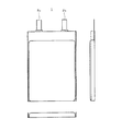
図1に、非特許文献1に開示されている電池1の外観を示す。
この薄型電池1は、正極と負極とをセパレーターを介して積層し巻回して作製した扁平型の電池素子を、アルミラミネートフィルムで外装し、電池素子の周囲を封止して作製されたものである。
正極及び負極と接続された正極端子2a及び負極端子2bは、例えば薄型電池1の一辺から電池外部に導出されており、電池素子周囲の一辺を残して封止した後、封止していない開口から電解液を注液し、最後に正極端子2a及び負極端子2bの導出辺を封止することにより、上述のような薄型電池を得ることができる。
In FIG. 1, the external appearance of the
This
The
この薄型電池は、100μm程度の厚さを有するアルミラミネートフィルムを外装とするため、金属缶と比較して強度が弱く、このままの状態で電池パックとして用いるのは困難である。そこで、プラスチックから成るパック筐体に、ラミネートフィルムで外装した電池素子を収容し、両面テープなどによって強固に固定した電池パックが広く用いられている。また、この電池パックを落下させた際の耐性は、筐体の肉厚を厚くすることにより向上できることが知られている。 Since this thin battery has an aluminum laminate film having a thickness of about 100 μm as an exterior, its strength is weaker than that of a metal can, and it is difficult to use it as it is in a battery pack. Therefore, a battery pack in which a battery element covered with a laminate film is accommodated in a pack housing made of plastic and firmly fixed with a double-sided tape or the like is widely used. Further, it is known that the resistance when the battery pack is dropped can be improved by increasing the thickness of the casing.
しかしながら、かかる従来の薄型電池においては、電池の表面と筐体の接着箇所が限られているため、落下高さがある程度の高さになると、電池素子そのものにダメージは無くとも、軟質の電池外装に加重が集中して断裂したり、金属層にピンホールが発生し樹脂層を透過して内部に水分が浸入することがある。 However, in such a conventional thin battery, since the bonding location between the surface of the battery and the housing is limited, if the drop height reaches a certain height, the battery element itself is not damaged, but the soft battery exterior In some cases, the load concentrates on the metal layer and tears, or pinholes are generated in the metal layer and the resin layer penetrates and moisture enters.
この場合、パック外観に変形等が無く機器に装着して使用できても、外装が断裂していると、大気中の水分が電極や電解質と反応し有害なガスが発生し続け、ピンホールだけのときでも、充電時に浸入水分が一気に反応してガス化することにより、電池パックが異常に膨れ、携帯機器を破損する虞がある。
また、パック筐体を製作する際、プラスチックの薄肉成型の技術的限界や強度確保のため、おおよそ300μm以上の肉厚が必要となり、収容できる電池体積を大きくすることが困難であった。
In this case, even if the exterior of the pack is not deformed and can be used by being attached to the device, if the exterior is torn, moisture in the atmosphere will continue to react with the electrode and electrolyte, generating harmful gases, and only the pinhole Even in this case, the intrusion moisture reacts and gasifies at a time during charging, so that the battery pack may be abnormally swollen and the portable device may be damaged.
Further, when manufacturing a pack housing, a thickness of approximately 300 μm or more is necessary to ensure the technical limit and strength of thin plastic molding, and it is difficult to increase the capacity of the battery that can be accommodated.
本発明は、このような従来技術の有する課題に鑑みてなされたものであり、その目的とするところは、軟質外装材への加重集中を抑制して落下後の信頼性や安全性を高め、軽微な落下時には変形などに耐え得る強度を兼ね備えつつ、万が一軟質外装材に損傷が生ずるような衝撃時には、引き続き対象機器への装填や充電が不可能なような認知性に優れ、且つ収容できる電池素子体積を最大限に拡大できる体積効率に優れた電池パックを提供することにある。 The present invention has been made in view of such problems of the prior art, and the object of the present invention is to increase the reliability and safety after dropping by suppressing weighted concentration on the soft exterior material, Batteries that are strong enough to withstand deformation, etc. in the event of a slight drop, and have excellent cognition that can not be loaded or charged in the target device in the event of an impact that would cause damage to the soft exterior material. An object of the present invention is to provide a battery pack excellent in volume efficiency that can maximize the element volume.
本発明者らは、上記目的を達成すべく鋭意検討を重ねた結果、軟質外装材と硬質外装材との接合状態を適切に制御することにより、上記目的が達成できることを見出し、本発明を完成するに至った。 As a result of intensive studies to achieve the above object, the present inventors have found that the above object can be achieved by appropriately controlling the bonding state between the soft exterior material and the hard exterior material, thereby completing the present invention. It came to do.
即ち、本発明の第1の電池パックは、正極と負極をセパレータを介して巻回又は積層して成り、非水電解質組成物を有する電池素子と、
熱接着層、金属層及び外装層を順次積層した構造を有するラミネートフィルムから成り、電池素子の主要部を外装する軟質外装材と、
熱接着層、金属層及び外装層を順次積層した3層構造を有するラミネートフィルムから成り、電池素子の残部と軟質外装材を外装する硬質外装材と、
接着部材と、
正極と負極の電極端子を外部に導出したまま、電池素子の周囲に沿って軟質外装材と硬質外装材とを接合させて電池素子を封止して成る非水電解質二次電池と、
硬質外装材に収容され非水電解質二次電池の電圧及び電流を制御可能な保護回路基板と、を備え、
電池素子と軟質外装材とが密着しており、
電池素子の周囲部分において、軟質外装材と硬質外装材とが、互いに対向する軟質外装材の熱接着層および硬質外装材の熱接着層が融解することにより、接合し、
軟質外装材の外装層は、その熱伝導率が1Wm-1K-1以下で、且つ硬質外装材の熱接着層よりも溶融温度が高く、
硬質外装材を、電池素子を包み込むようにして折り返し、折り返した硬質外装材の端部と、電池素子の主要部を外装する軟質外装材の表面とが、軟質外装材の外装層が融けず且つ接着部材が融けることにより接合されていることを特徴とする。
That is, the first battery pack of the present invention is formed by winding or laminating a positive electrode and a negative electrode with a separator interposed therebetween, and a battery element having a nonaqueous electrolyte composition,
A soft exterior material comprising a laminate film having a structure in which a thermal adhesive layer, a metal layer and an exterior layer are sequentially laminated, and exteriors the main part of the battery element;
A hard exterior material comprising a laminate film having a three-layer structure in which a thermal adhesive layer, a metal layer, and an exterior layer are sequentially laminated, and covering the remainder of the battery element and the soft exterior material;
An adhesive member;
A non-aqueous electrolyte secondary battery formed by sealing a battery element by bonding a soft exterior material and a hard exterior material along the periphery of the battery element, with the electrode terminals of the positive electrode and the negative electrode being led out to the outside,
A protective circuit board housed in a hard exterior material and capable of controlling the voltage and current of the non-aqueous electrolyte secondary battery,
The battery element and the soft exterior material are in close contact,
In the peripheral portion of the battery element, the soft exterior material and the hard exterior material are joined together by melting the thermal adhesive layer of the soft exterior material and the thermal adhesive layer of the hard exterior material facing each other,
The exterior layer of the soft exterior material has a thermal conductivity of 1 Wm −1 K −1 or less and a melting temperature higher than that of the thermal adhesion layer of the hard exterior material,
The hard exterior material is folded so as to wrap the battery element, and the end of the folded hard exterior material and the surface of the soft exterior material that covers the main part of the battery element are not melted and the exterior layer of the soft exterior material does not melt The adhesive member is joined by melting.
本発明によれば、軟質外装材と硬質外装材との接合状態を適切に制御することとしたため、軟質外装材への加重集中を抑制して落下後の信頼性や安全性を高め、軽微な落下時には変形などに耐え得る強度を兼ね備えつつ、万が一軟質外装材に損傷が生ずるような衝撃時には、引き続き対象機器への装填や充電が不可能なような認知性に優れ、且つ収容できる電池素子体積を最大限に拡大できる体積効率に優れた電池パックを提供することができる。 According to the present invention, since the joining state between the soft exterior material and the hard exterior material is appropriately controlled, the weight concentration on the soft exterior material is suppressed, and the reliability and safety after the fall are improved. A battery element volume that has excellent strength that can not be loaded or charged into the target device and can be accommodated in the event of an impact that would cause damage to the soft exterior material in the unlikely event that it has the strength to withstand deformation when dropped. Thus, it is possible to provide a battery pack excellent in volumetric efficiency that can be expanded to the maximum.
以下、本発明の電池パックにつき図面を参照しながら詳細に説明する。なお、本明細書において、濃度、含有量及び配合量などのついての「%」は、特記しない限り質量百分率を表すものとする。 Hereinafter, the battery pack of the present invention will be described in detail with reference to the drawings. In the present specification, “%” for concentration, content, blending amount, etc. represents mass percentage unless otherwise specified.
(実施形態1)
この実施形態では、外装材として4層構造の硬質ラミネートフィルムを用いる構成について説明する。
図2に、本発明の電池パックの一実施形態を表すリチウムイオンポリマー二次電池の電池パックの外観を示す。この電池パック40は、硬質外装材としての硬質ラミネートフィルム41に、非水電解質二次電池の一例であるリチウムイオンポリマー電池を収容し、両端開口部に樹脂成型カバーであるトップカバー42及びリアカバー43を嵌合したものであり、必要に応じて製品ラベル46が配設されている。
(Embodiment 1)
In this embodiment, a configuration using a four-layer hard laminate film as an exterior material will be described.
In FIG. 2, the external appearance of the battery pack of the lithium ion polymer secondary battery showing one Embodiment of the battery pack of this invention is shown. This battery pack 40 contains a lithium ion polymer battery, which is an example of a nonaqueous electrolyte secondary battery, in a
ここで、この実施形態1及び次の実施形態2では、電池素子を軟質外装材である軟質ラミネートフィルムで外装したものを電池、電池を硬質ラミネートフィルム41で外装したものを電池アセンブリ、電池アセンブリに回路基板を接続し、トップカバー42及びリアカバー43を嵌合した、図2のような構成のものを電池パックと称することにする。
Here, in the first embodiment and the second embodiment, the battery element is packaged with a soft laminate film, which is a soft sheath material, and the battery is packaged with a
図3に、電池パック40の構成を示す。電池パック40は、電池素子が軟質ラミネートフィルムで外装された電池50と、回路基板44と、トップカバー42及びリアカバー43から構成されており、電池50が硬質ラミネートフィルム41で被覆されている。
FIG. 3 shows the configuration of the battery pack 40. The battery pack 40 includes a
トップカバー42は、正極及び負極が導出されるトップ部に設けられ、電池アセンブリの開口部に嵌合される樹脂成型カバーである。また、リアカバー43は、電池のボトム部に設けられ、電池アセンブリ45の開口部に嵌合される樹脂成型カバーである。
トップカバー42及びリアカバー43は、電池アセンブリ45の開口部に嵌合した後、熱融着等で電池アセンブリ45に接着される。トップカバー42は、上部ホルダー42a及び下部ホルダー42bが嵌合されてなり、上部ホルダー42aと下部ホルダー42bとの間には回路基板44が配置される。
The top cover 42 is a resin-molded cover that is provided at the top portion from which the positive electrode and the negative electrode are led out and fitted into the opening of the battery assembly. The rear cover 43 is a resin-molded cover that is provided at the bottom of the battery and fitted into the opening of the
The top cover 42 and the rear cover 43 are bonded to the
回路基板44は、保護回路が予めマウントされており、電池50から導出された正極端子及び負極端子と保護回路とが抵抗溶接、超音波溶接等で接続されている。保護回路は、PTC素子(Positive Temperature Coefficient;熱感抵抗素子)、サーミスタ等、電池が高温となった場合に電池の電流回路を遮断する温度保護素子を有する。
なお、この電池パック40は、図示しない電気機器との接続端子を有しており、トップカバー42には、電気機器との接続端子を露出させた端子窓が設けられている。
The circuit board 44 has a protection circuit mounted in advance, and the positive terminal and the negative terminal derived from the
The battery pack 40 has a connection terminal with an electric device (not shown), and the top cover 42 is provided with a terminal window exposing the connection terminal with the electric device.
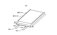
次に、電池素子について説明する。
図4は、この電池パック45に用いる電池素子59の構成を示す。
この電池素子59は、帯状の正極51と、セパレータ53aと、正極51に対向して配された帯状の負極52と、セパレータ53bとを順に積層し、長手方向に巻回されており、図示しないゲル状電解質が正極51及び負極52の両面に塗布されている。
また、電池素子59からは、正極51と接続された正極端子55a及び負極52と接続された負極端子55bが導出されており、正極端子55a及び負極端子55bのそれぞれの両面には後に外装するラミネートフィルムとの接着性を向上させるために樹脂片56a及び56bが被覆されている。なお、電解液を用いる場合は、後に電解液の注液工程を設ける。
Next, the battery element will be described.
FIG. 4 shows the configuration of the
The
Also, a
以下、電池素子59を構成する材料について詳しく説明する。
Hereinafter, materials constituting the
[正極]
正極51は、正極活物質を含有する正極活物質層51aが、正極集電体51bの両面上に形成されてなる。正極集電体51bとしては、例えばアルミニウム(Al)箔などの金属箔により構成されている。
[Positive electrode]
The
正極活物質層51aは、例えば正極活物質と、導電剤と、結着剤とを含有して成る。これらを均一に混合して正極合剤とし、この正極合剤を溶剤中に分散させてスラリー状にする。次いで、このスラリーをドクターブレード法等により正極集電体51b上に均一に塗布し、高温で乾燥させて溶剤を飛散させることにより形成することができる。
なお、正極活物質、導電剤、結着剤及び溶剤は、均一に分散していればよく、その混合比は問われない。
The positive electrode
Note that the positive electrode active material, the conductive agent, the binder, and the solvent only need to be uniformly dispersed, and the mixing ratio is not limited.
正極活物質としては、LiXMO2(式中のMは、少なくとも1種の遷移金属を示し、xは、電池の充放電状態によって異なり、通常0.05〜1.10である)を主体とする、リチウムと遷移金属との複合酸化物が用いられる。リチウム複合酸化物を構成する遷移金属としては、コバルト(Co),Ni,マンガン(Mn)等が用いられる。 The positive electrode active material is mainly LiXMO 2 (M in the formula represents at least one transition metal, and x varies depending on the charge / discharge state of the battery and is usually 0.05 to 1.10). A composite oxide of lithium and a transition metal is used. As the transition metal constituting the lithium composite oxide, cobalt (Co), Ni, manganese (Mn) or the like is used.
このようなリチウム複合酸化物として、具体的には、LiCoO2、LiNiO2、LiMn2O4、LiNiyCo1-yO2(0<y<1)等が挙げられる。
また、遷移金属元素の一部を他の元素に置換した固溶体も使用可能である。LiNi0.5Co0.5O2、LiNi0.8Co0.2O2等がその例として挙げられる。これらのリチウム 複合酸化物は、高電圧を発生でき、エネルギー密度が優れたものである。さらに、正極活物質としてTiS2、MoS2、NbSe2、V2O5等のリチウムを有しない金属硫化物又は酸化物を使用してもよい。
Specific examples of such a lithium composite oxide include LiCoO 2 , LiNiO 2 , LiMn 2 O 4 , LiNi y Co 1-y O 2 (0 <y <1).
A solid solution in which a part of the transition metal element is substituted with another element can also be used. Examples thereof include LiNi 0.5 Co 0.5 O 2 and LiNi 0.8 Co 0.2 O 2 . These lithium composite oxides can generate a high voltage and have an excellent energy density. Furthermore, TiS 2, MoS 2, may be used NbSe 2, V 2 O no lithium metal sulfides such as 5 or oxide as the positive electrode active material.
また、導電剤としては、例えばカーボンブラックやグラファイトなどの炭素材料等が用いられる。また、結着剤としては、例えばポリフッ化ビニリデン、ポリテトラフルオロエチレン、ポリビニリデンフルオライド等が用いられる。また、溶剤としては、例えばN−メチルピロリドン等が用いられる。 As the conductive agent, for example, a carbon material such as carbon black or graphite is used. As the binder, for example, polyvinylidene fluoride, polytetrafluoroethylene, polyvinylidene fluoride, or the like is used. Moreover, as a solvent, N-methylpyrrolidone etc. are used, for example.
正極51は、集電体の一端部にスポット溶接又は超音波溶接で接続された正極端子15aを有している。この正極端子55aとしては、金属箔や網目状のものが望ましいが、電気化学的及び化学的に安定であり、導通がとれるものであれば金属でなくとも問題はない。
正極端子55aの材料としては、例えばAl等が挙げられる。
The
Examples of the material of the
[負極]
負極52は、負極活物質を含有する負極活物質層52aが、負極集電体52bの両面上に形成されてなる。負極集電体52bとしては、例えば銅(Cu)箔,Ni箔及びステンレス箔などの金属箔により構成されている。
[Negative electrode]
The
負極活物質層52aは、例えば負極活物質と、必要であれば導電剤と、結着剤とを含有して構成されている。これらを均一に混合して負極合剤とし、この負極合剤を溶剤中に分散させてスラリー状にする。次にこのスラリーをドクターブレード法等により負極集電体52b上に均一に塗布し、高温で乾燥させて溶剤を飛散させることにより負極活物質層52aが形成される。ここで、負極活物質、導電剤、結着剤及び溶剤は、均一に分散していればよく、その混合比は問われない。
The negative electrode
負極活物質としては、リチウム金属、リチウム合金又はリチウムをドープ・脱ドープ可能な炭素材料又は金属系材料と炭素系材料との複合材料が用いられる。
具体的に、リチウムをドープ・脱ドープ可能な炭素材料としては、グラファイト、難黒鉛化炭素、易黒鉛化炭素等が挙げられ、より具体的には、熱分解炭素類、コークス類(ピッチコークス、ニードルコークス、石油コークス)、黒鉛類、ガラス状炭素類、有機高分子化合物焼成体(フェノール樹脂、フラン樹脂等を適当な温度で焼成し炭素化したもの)、炭素繊維、活性炭等の炭素材料を使用することができる。更に、リチウムをドープ、脱ドープできる材料としては、ポリアセチレン、ポリピロール等の高分子やSnO2等の酸化物を使用することができる。
As the negative electrode active material, lithium metal, a lithium alloy, a carbon material that can be doped / undoped with lithium, or a composite material of a metal-based material and a carbon-based material is used.
Specifically, examples of the carbon material that can be doped / dedoped with lithium include graphite, non-graphitizable carbon, graphitizable carbon, and the like. More specifically, pyrolytic carbons, cokes (pitch coke, Needle coke, petroleum coke), graphites, glassy carbons, organic polymer compound fired bodies (carbonized by firing phenol resin, furan resin, etc.), carbon fiber, activated carbon, etc. Can be used. Furthermore, as a material that can be doped or dedoped with lithium, a polymer such as polyacetylene or polypyrrole or an oxide such as SnO 2 can be used.
また、リチウムを合金化可能な材料としては多様な種類の金属等が使用可能であるが、スズ(Sn)、コバルト(Co)、インジウム(In)、Al、ケイ素(Si)及びこれらの合金がよく用いられる。金属リチウムを使用する場合は、必ずしも粉体を結着剤で塗布膜にする必要はなく、圧延したLi金属板でも構わない。
結着剤としては、例えばポリフッ化ビニリデン、スチレンブタジエンゴム等が用いられる。また、溶剤としては、例えばN−メチルピロリドン、メチルエチルケトン等が用いられる。
In addition, various kinds of metals can be used as materials capable of alloying lithium, but tin (Sn), cobalt (Co), indium (In), Al, silicon (Si), and alloys thereof can be used. Often used. When metal lithium is used, it is not always necessary to use powder as a coating film with a binder, and a rolled Li metal plate may be used.
As the binder, for example, polyvinylidene fluoride, styrene butadiene rubber or the like is used. Moreover, as a solvent, N-methylpyrrolidone, methyl ethyl ketone, etc. are used, for example.
負極52も正極51と同様に、負極集電体52bの一端部にスポット溶接又は超音波溶接で接続された負極端子55bを有している。この負極端子52bは金属箔、網目状のものが望ましいが、電気化学的及び化学的に安定であり、導通がとれるものであれば金属でなくとも問題はない。負極端子52bの材料としては、例えば銅、Ni等が挙げられる。
Similarly to the
なお、正極端子55a及び負極端子55bは同じ方向から導出されていることが好ましいが、短絡等が起こらず電池性能にも問題がなければ、どの方向から導出されていても問題はない。また、正極端子55a及び負極端子55bの接続箇所は、電気的接触がとれているのであれば取り付ける場所、取り付ける方法は上記の例に限られない。
The
[電解質]
電解質、即ち非水電解質組成物は、リチウムイオン電池に一般的に使用される電解質塩と非水溶媒が使用可能である。
非水溶媒としては、具体的には、エチレンカーボネート(EC)、プロピレンカーボネート(PC)、γ−ブチロラクトン、ジメチルカーボネート、ジエチルカーボネート、エチルメチルカーボネート、ジプロピルカーボネート、エチルプロピルカーボネート、及びこれらの炭酸エステル類の水素をハロゲンに置換した溶媒等が挙げられる。
これらの溶媒については、その1種を単独で用いてもよいし、複数種を所定の組成で混合してもよい。
[Electrolytes]
As the electrolyte, that is, the non-aqueous electrolyte composition, an electrolyte salt and a non-aqueous solvent generally used for lithium ion batteries can be used.
Specific examples of the non-aqueous solvent include ethylene carbonate (EC), propylene carbonate (PC), γ-butyrolactone, dimethyl carbonate, diethyl carbonate, ethyl methyl carbonate, dipropyl carbonate, ethylpropyl carbonate, and carbonates thereof. And other solvents in which hydrogen is substituted with halogen.
About these solvents, the 1 type may be used independently and multiple types may be mixed by predetermined composition.
電解質塩としては、上記非水溶媒に溶解するものが用いられ、カチオンとアニオンが組み合わされてなる。カチオンにはアルカリ金属やアルカリ土類金属が用いられる。アニオンには、Cl-,Br-,I-,SCN-,ClO4 -,BF4 -,PF6 -,CF3SO3 -等が用いられる。
具体的には、LiPF6、LiBF4、LiN(CF3SO2)2、LiN(C2F5SO2)2、LiClO4等が挙げられる。電解質塩濃度としては、上記溶媒に溶解することができる濃度であれば問題ないが、リチウムイオン濃度が非水溶媒に対して0.4mol/kg以上、2.0mol/kg以下の範囲であることが好ましい。
As the electrolyte salt, one that dissolves in the non-aqueous solvent is used, and a combination of a cation and an anion is used. As the cation, an alkali metal or an alkaline earth metal is used. As the anion, Cl − , Br − , I − , SCN − , ClO 4 − , BF 4 − , PF 6 − , CF 3 SO 3 − and the like are used.
Specifically, LiPF 6, LiBF 4, LiN (CF 3 SO 2) 2, LiN (C 2 F 5 SO 2) 2, LiClO 4 and the like. The electrolyte salt concentration is not a problem as long as it can be dissolved in the above solvent, but the lithium ion concentration is in the range of 0.4 mol / kg or more and 2.0 mol / kg or less with respect to the non-aqueous solvent. Is preferred.
ゲル状電解質を用いる場合は、電解質及び電解塩を混合した電解液をマトリクスポリマでゲル化することでゲル状電解質を得る。
マトリクスポリマは、非水溶媒に電解質塩が溶解されてなる非水電解液に相溶可能であり、ゲル化できるものであればよい。
このようなマトリクスポリマとしては、ポリフッ化ビニリデン、ポリエチレンオキサイド、ポリプロピレンオキサイド、ポリアクリロニトリル、ポリメタクリロニトリルを繰り返し単位に含むポリマーが挙げられる。このようなポリマーについては、その1種を単独で用いてもよいし、2種類以上を混合して用いてもよい。
In the case of using a gel electrolyte, a gel electrolyte is obtained by gelling an electrolyte solution in which an electrolyte and an electrolyte salt are mixed with a matrix polymer.
The matrix polymer is not particularly limited as long as it is compatible with a nonaqueous electrolytic solution obtained by dissolving an electrolyte salt in a nonaqueous solvent and can be gelled.
Examples of such a matrix polymer include a polymer containing polyvinylidene fluoride, polyethylene oxide, polypropylene oxide, polyacrylonitrile, and polymethacrylonitrile in repeating units. About such a polymer, the 1 type may be used independently, and 2 or more types may be mixed and used for it.
[セパレータ]
セパレータは、例えばポリプロピレン(PP)やポリエチレン(PE)などのポリオレフィン系の材料から成る多孔質膜、又はセラミック製の不織布などの無機材料よりなる多孔質膜により構成されており、これら2種以上の多孔質膜を積層した構造とされていてもよい。中でも、ポリエチレン、ポリプロピレンの多孔質フィルムが最も有効である。
[Separator]
The separator is composed of, for example, a porous film made of a polyolefin-based material such as polypropylene (PP) or polyethylene (PE), or a porous film made of an inorganic material such as a ceramic nonwoven fabric. A structure in which a porous film is laminated may be used. Among these, polyethylene and polypropylene porous films are the most effective.
一般的にセパレータの厚みは5〜50μmが好適に使用可能であるが、7〜30μmがより好ましい。セパレータは、厚すぎると活物質の充填量が低下して電池容量が低下するとともに、イオン伝導性が低下して電流特性が低下する。逆に薄すぎると、膜の機械的強度が低下する。 In general, the thickness of the separator is preferably 5 to 50 μm, more preferably 7 to 30 μm. If the separator is too thick, the amount of the active material filled decreases, the battery capacity decreases, and the ionic conductivity decreases and the current characteristics deteriorate. On the other hand, if the film is too thin, the mechanical strength of the film decreases.
[電池の作製]
上述のようにして作製したゲル状電解質溶液を正極51及び負極52に均一に塗布し、正極活物質層51a及び負極活物質層52aに含浸させた後、常温で保存するか又は、乾燥工程を経てゲル状電解質層を形成する。次いで、ゲル状電解質層を形成した正極51及び負極52を用い、正極51、セパレータ53a、負極52、セパレータ53bの順に積層して巻回し、電池素子59とする。
[Production of battery]
The gel electrolyte solution prepared as described above is uniformly applied to the
次いで、電池素子59を軟質ラミネートフィルム57にて外装し成型することにより、図5で示すような電池50を作製する。
ここで、軟質ラミネートフィルム57としては、図6で示す構成のラミネートフィルムを用いることができる。軟質ラミネートフィルム57は、符号61で示される金属箔が、樹脂フィルムから成る外装層62及び樹脂フィルムから成る熱接着層(以下、シーラント層と適宜称する)63に挟まれた、防湿性、絶縁性を有する多層フィルムから成る。
なお、外装層62、金属箔61、シーラント層63の厚みは、特に限定されるものではないが、それぞれ15μm程度、35μm程度、30μm程度である。
Next, the
Here, as the
The thicknesses of the exterior layer 62, the metal foil 61, and the sealant layer 63 are not particularly limited, but are about 15 μm, about 35 μm, and about 30 μm, respectively.
金属箔61は、外装材の強度向上の他、水分、酸素、光の進入を防ぎ内容物を守る最も重要な役割を担っており、ステンレスやニッケルメッキを施した鉄等を材料として適宜用いることができるが、軽さ、伸び性、価格、加工のしやすさからアルミニウム(Al)が最も好適であり、特に8021O又は8079O等のアルミニウムを用いるのが好ましい。
また、金属箔61と外装層62及びシーラント層63のそれぞれは接着剤層64及び65を介して貼り合わされている。
上記外装層62やシーラント層63が金属との熱接着性を有している場合や、金属表面に上記外装層63やシーラント層63との熱接着が可能な下地層を形成する場合は、上記接着剤層64は省略が可能である。
The metal foil 61 plays the most important role of protecting the contents by preventing the ingress of moisture, oxygen and light in addition to improving the strength of the exterior material, and appropriately uses stainless steel or nickel-plated iron as a material. However, aluminum (Al) is most suitable from the viewpoint of lightness, extensibility, cost, and ease of processing, and it is particularly preferable to use aluminum such as 8021O or 8079O.
Further, the metal foil 61, the exterior layer 62, and the sealant layer 63 are bonded together via adhesive layers 64 and 65.
When the exterior layer 62 and the sealant layer 63 have thermal adhesiveness with a metal, or when a base layer capable of thermal adhesion with the exterior layer 63 and the sealant layer 63 is formed on the metal surface, The adhesive layer 64 can be omitted.
外装層62には、外観の美しさや強靱さ、耐熱性、柔軟性などから、ポリオレフィン、ポリアミド、ポリイミド及びポリエステル、具体的には、ナイロン(Ny)、ポリエチレンテレフタレート(PET)、ポリエチレン(PE)、ポリエチレンナフタレート(PEN)が用いられ、これらから複数種類選択して用いることも可能である。 The exterior layer 62 is made of polyolefin, polyamide, polyimide and polyester, specifically nylon (Ny), polyethylene terephthalate (PET), polyethylene (PE) due to the beauty of appearance, toughness, heat resistance and flexibility. Polyethylene naphthalate (PEN) is used, and a plurality of these can be selected and used.
また、シーラント層63は、熱や超音波で融け、互いに融着する部分であり、ポリエチレン(PE)、無延伸ポリエチレン(CPE)、無延伸ポリプロピレン(CPP)、ポリエチレンテレフタレート(PET)、ナイロン(Ny)の他、低密度ポリエチレン(LDPE)、高密度ポリエチレン(HDPE)、直鎖状低密度ポリエチレン(LLDPE)が使用可能であり、これらから複数種類選択して用いることも可能である。 Further, the sealant layer 63 is a portion that is melted by heat or ultrasonic waves and fused to each other, and is polyethylene (PE), unstretched polyethylene (CPE), unstretched polypropylene (CPP), polyethylene terephthalate (PET), nylon (Ny ), Low-density polyethylene (LDPE), high-density polyethylene (HDPE), and linear low-density polyethylene (LLDPE) can be used, and a plurality of types can be selected and used.
ラミネートフィルムの最も一般的な構成は、外装層/金属箔/シーラント層=Ny/Al/CPPである。また、この組み合わせばかりでなく、以下に示すような他の一般的なラミネートフィルムの構成を採用することができる。
即ち、外装層/金属膜/シーラント層=Ny/Al/PE、PET/Al/CPP、PET/Al/PET/CPP、PET/Ny/Al/CPP、PET/Ny/Al/Ny/CPP、PET/Ny/Al/Ny/PE、Ny/PE/Al/LLDPE、PET/PE/Al/PET/LDPE、又はPET/Ny/Al/LDPE/CPPとすることができる。なお、金属箔としてはAl以外の金属を採用することができることは勿論である。
The most common configuration of the laminate film is: exterior layer / metal foil / sealant layer = Ny / Al / CPP. Moreover, not only this combination but the structure of the other general laminate film as shown below is employable.
That is, exterior layer / metal film / sealant layer = Ny / Al / PE, PET / Al / CPP, PET / Al / PET / CPP, PET / Ny / Al / CPP, PET / Ny / Al / Ny / CPP, PET / Ny / Al / Ny / PE, Ny / PE / Al / LLDPE, PET / PE / Al / PET / LDPE, or PET / Ny / Al / LDPE / CPP. Of course, a metal other than Al can be used as the metal foil.
図7に示すように、軟質ラミネートフィルム57は深絞りにより凹部57aを形成し、この凹部57aに電池素子59を収容した後、さらに軟質ラミネートフィルム57が凹部57aの開口部を覆うようにする。
次いで、電池素子59の周辺部の三辺を減圧下で熱融着することにより封止して、電池50とする。かかる減圧下での熱融着によって、電池素子59は、軟質ラミネートフィルム57と密着する。
As shown in FIG. 7, the
Next, three sides of the periphery of the
電解液を用いた電池の場合は、このときに電解液を注液する。まず、電池素子の周辺部の2辺を熱融着した後、残る開口部から所定量の電解液を注液し、最後にこの開口部を熱融着することにより、電池が得られる。 In the case of a battery using an electrolytic solution, the electrolytic solution is injected at this time. First, after two sides of the peripheral portion of the battery element are heat-sealed, a predetermined amount of electrolyte is injected from the remaining opening, and finally, the opening is heat-sealed to obtain a battery.
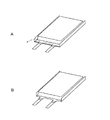
電池50は、後の製造工程を考慮して、トップ部の不必要な部分をトリミングにより削除してもよい。図8A及び図8Bに示すように、参照符号Pの線に沿ってトリミングを施すことにより、例えばトップカバーと軟質ラミネートフィルムとの干渉を減少させることができる。
The
[電池アセンブリの作製]
このようにして作製した電池を、硬質ラミネートフィルムで外装し、電池アセンブリを作製する。まず、硬質ラミネートフィルムの構成について説明する。
[Production of battery assembly]
The battery thus produced is covered with a hard laminate film to produce a battery assembly. First, the configuration of the hard laminate film will be described.
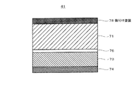
図9に示すように、硬質ラミネートフィルム41は、符号71で示される金属箔が、樹脂フィルムから成る外装層72及び樹脂フィルムから成るシーラント層73に挟まれ、更にシーラント層73の下に接着層74を有する、防湿性、絶縁性を有する多層フィルムからなる。なお、本実施形態では、シーラント層73と接着層74とで、ナイロン等に対して熱接着性を有する熱接着層(複合接着層)を形成している。
As shown in FIG. 9, the
硬質ラミネートフィルム41において、外装層72、金属箔71、熱接着層(シーラント層73+接着層74)の厚みは、特に限定されるものではないが、それぞれ115μm以下、330μm以下、25〜50μm程度(シーラント層)、1〜5μm程度(接着層)である。
得られる強度を確保するため材質を硬質としているが、外装層72の厚みを115μm以下、金属箔71の厚みを330μm以下としたのは、熱伝導の抵抗が増大しないようにするためである。
In the
The material is hard in order to ensure the obtained strength, but the thickness of the exterior layer 72 is set to 115 μm or less and the thickness of the
金属箔71としては、硬質の金属材料が用いられ、アルミニウムやステンレス、又は銅、チタン、ブリキ、トタン、ニッケルメッキを施した鉄等を材料として適宜用いることができる。中でも、アルミニウム(Al)及びステンレス(SUS)が最も好適であり、特に3003−H18、3004−H18、1N30−H18等のアルミニウム又はSUS304やSUS430等のステンレスを用いるのが好ましい。
As the
外装層72には外観の美しさや強靱さ、耐熱性、柔軟性などからナイロン(Ny)、又はポリエチレンテレフタレート(PET)、ポリエチレンナフタレート(PEN)が用いられ、これらから複数種類選択して用いることも可能である。 Nylon (Ny), polyethylene terephthalate (PET), or polyethylene naphthalate (PEN) is used for the exterior layer 72 in view of beauty of appearance, toughness, heat resistance, flexibility, and the like. It is also possible.
シーラント層73は、熱や超音波で溶け、互いに融着する部分であり、ポリエチレン(PE)、無軸延伸ポリプロピレン(CPP)、ポリエチレンテレフタレート(PET)、ナイロン(Ny)の他、低密度ポリエチレン(LDPE)、高密度ポリエチレン(HDPE)、直鎖状低密度ポリエチレン(LLDPE)が使用可能であり、これらから複数種類選択して用いることも可能である。
The
熱接着層74は、別に接着用部材を設けることなく、軟質ラミネートフィルム57で外装された電池50と硬質ラミネートフィルム41とを接着するためのものである。
熱接着層74としては、軟質ラミネートフィルム57の外装層として用いられるNy,PET、PEN等との接着性に優れ、その溶融温度が電池素子に影響を与えない程度である樹脂材料が用いられる。また、熱接着層74は、シーラント層73に用いる材料よりも低い融点の樹脂材料を用いる。
The
As the
具体的には、エチレン酢酸ビニルコポリマー(EVA)、エチレンアクリル酸コポリマー、アクリル酸エチルコポリマー、アクリル酸メチルコポリマー、メタクリル酸コポリマー、メタクリル酸メチルコポリマー、ポリアクリロニトリル、エチレンビニルアルコール樹脂、ポリアミド樹脂、ポリエステル樹脂、酸変成したポリプロピレン、アイオノマーが使用可能であり、これらから複数種類選択して用いることも可能である。これら材料は、ホットメルト剤、フィルム又は耐候性の粘着剤として用いることができる。 Specifically, ethylene vinyl acetate copolymer (EVA), ethylene acrylic acid copolymer, ethyl acrylate copolymer, methyl acrylate copolymer, methacrylic acid copolymer, methyl methacrylate copolymer, polyacrylonitrile, ethylene vinyl alcohol resin, polyamide resin, polyester resin Acid-modified polypropylene and ionomers can be used, and a plurality of types can be selected and used. These materials can be used as a hot melt agent, a film, or a weather-resistant adhesive.
シーラント層73は、後にトップカバー42及びリアカバー43を熱融着する際に融着層として用いられる。このため、トップカバー42及びリアカバー43と接着性のよい樹脂材料が選択される。また、硬質ラミネートフィルム41を電池50に接着する際のクッション機能も有する。
即ち、電池50の外装材である軟質ラミネートフィルム57と硬質ラミネートフィルム41を、熱接着層74を介して熱融着する際、ラミネートフィルムそれぞれが表面に微細な凹凸を有していることから接着性が良好でないことがある。25〜50μm程度の厚さを有するシーラント層73が設けられていることにより、シーラント層73がクッションの役割を果たし、表面の微細な凹凸を有するラミネートフィルム同士を良好に接着させることができる。
The
That is, when the
ここで、本発明の特徴をなす軟質外装材と硬質外装材との接合状態について説明する。
上述のように、本発明の電池パックにおいては、軟質外装材と硬質外装材とが、軟質外装材の外装層が融けず且つ硬質外装材の接着層が融けることにより、接合している、即ち、具体的には、軟質ラミネートフィルム57と硬質ラミネートフィルム41とが接着しているが、軟質ラミネートフィルム57の外装層62が融けておらず、且つ硬質ラミネートフィルム41の熱接着層(シーラント層73+接着層74)が融けた状態となっている。
Here, the joining state of the soft exterior material and the hard exterior material that characterize the present invention will be described.
As described above, in the battery pack of the present invention, the soft exterior material and the hard exterior material are joined by melting the exterior layer of the soft exterior material and melting the adhesive layer of the hard exterior material, that is, Specifically, the
このような接合状態を実現することにより、電池パックが落下などにより衝撃を受け、硬質ラミネートフィルム57と軟質ラミネートフィルム41との間に剥離応力が過大にかかった際に、軟質ラミネートフィルム41が伸ばされ、ピンホールや破れを発生してしまう前に、硬質ラミネートフィルム57が外れる程度の強度にすることができる。また、軽い応力がかかった際にも大気圧と軟質ラミネートフィルム41の引っ張り強度により、硬質ラミネートフィルム57が電池素子と一体化し、変形に耐えることができる。
これにより、本発明の電池パックは、適切な強度を有し、軟質外装材がダメージを受けない程度の落下時にはパック外観に欠陥を与えることなく連続使用を可能とし、且つ軟質外装材がダメージを負うような落下時には硬質外装が優先的に剥離ないしは外れ、使用不可能なことが視認できるので、軟質外装の破損よるガス発生や機器を破壊するような電池膨れを未然に防止し得る電池パックを実現するものである。
By realizing such a joining state, when the battery pack receives an impact due to dropping or the like, and the peeling stress is excessively applied between the
As a result, the battery pack of the present invention has appropriate strength, and can be continuously used without causing defects in the pack appearance when the soft exterior material is not damaged, and the soft exterior material is damaged. It is possible to visually recognize that the hard exterior is peeled off or detached preferentially when it falls, so that it cannot be used, so a battery pack that can prevent the generation of gas due to breakage of the soft exterior and the expansion of the battery that destroys the device can be prevented. It is realized.
次に、上述のような接合状態を実現できる軟質外装材と硬質外装材との関係などについて説明する。
まず、互いに同種の材料を接合する場合は一般的に強度を強くでき、異種材料とすれば強度を一定レベル以下にすることが可能である。
また、接着対象の溶融温度よりも低い温度で溶融する材料を熱接着層として選択し、接着対象が溶融しない温度とすることで接着強度を所定のレベル以下にコントロールすることも可能である。
Next, the relationship between the soft exterior material and the hard exterior material that can realize the above-described bonded state will be described.
First, when joining the same kind of materials to each other, generally the strength can be increased, and when different materials are used, the strength can be reduced to a certain level or less.
It is also possible to control the adhesive strength to a predetermined level or less by selecting a material that melts at a temperature lower than the melting temperature of the bonding target as the thermal bonding layer and setting the temperature at which the bonding target does not melt.
本発明では、これらの技術を組み合わせ、軟質外装材の外装層の材料を例えばナイロンなど耐熱性のものとし、ナイロンが溶融しない温度で溶融して接着力を発現するナイロンと異なる材料である無延伸のポリプロピレンやEVAなどの材料を硬質外装材の熱接着層として配置することを骨子とし、上述のように、電池パックの落下時などこれら層間に剥離応力が過大にかかった際に、軟質外装材のラミネートフィルムが伸ばされ、ピンホールや破れに至ってしまう前に、硬質外装材が外れる程度の強度にとどまるようにしている。 In the present invention, these technologies are combined, the material of the exterior layer of the soft exterior material is made of heat resistant material such as nylon, and is a non-stretched material that is different from nylon that exhibits adhesive strength by melting at a temperature at which nylon does not melt It is important to arrange a material such as polypropylene or EVA as a heat-adhesive layer for a hard exterior material. As described above, when a peeling stress is excessively applied between these layers such as when the battery pack is dropped, a soft exterior material is used. Before the laminate film is stretched to reach pinholes or tears, the strength is such that the hard exterior material can be removed.
上述のことより、本発明では、軟質外装材の外装層を硬質外装材の熱接着層とは異なる材料とし、且つポリオレフィン、ポリアミド、ポリイミド又はポリエステル及びこれらの組み合わせに係る樹脂材料を延伸した延伸樹脂を、単独又は組み合わせて用いることが好ましい。 From the above, in the present invention, a stretched resin in which the exterior layer of the soft exterior material is different from the thermal adhesive layer of the hard exterior material, and the resin material according to polyolefin, polyamide, polyimide, polyester, or a combination thereof is stretched. Are preferably used alone or in combination.
なお、異種材料間や、片側の材料のみを溶融させる場合は接着が始まる温度と両材料が溶融してしまう温度との差が狭くなる傾向にある。これは、電池自体がヒートシンクであり電池が熱を奪い続ける限り、溶融する熱接着層が一定の温度に保たれることが困難だからである。
また、電池パックの製造に当たりヒーターの温度を調整した場合でも同様である。
接合時にシール界面を理想の温度に保持するには、加熱部からシール界面までに十分に速い熱伝達を実現することが必要で、且つ界面以降はある程度遅い熱伝達とし、蓄熱し易くなるようにすることが好ましい。
Note that, when different materials or only one material is melted, the difference between the temperature at which bonding starts and the temperature at which both materials melt tends to narrow. This is because, as long as the battery itself is a heat sink and the battery keeps taking heat away, it is difficult to maintain the molten heat bonding layer at a constant temperature.
The same applies when the temperature of the heater is adjusted in manufacturing the battery pack.
In order to keep the seal interface at an ideal temperature during joining, it is necessary to realize sufficiently fast heat transfer from the heating part to the seal interface, and after the interface, heat transfer is somewhat slow so that heat can be stored easily. It is preferable to do.
本発明においては、硬質外装材の外装層と金属層を積層した状態での面積当たりの熱伝導率を1000Wm-2K-1以上にすることが好ましく、これにより、熱接着層に十分な熱量を供給することができる。
また、接合、具体的には熱溶着で用いる熱源に対し、シール界面、即ち硬質外装材の熱接着層と軟質外装材の外装層との界面より電池素子側では、熱伝導率1以下の材料を配置することで、シール界面を一定温度に保持することができる。
特に、硬質外装材の外装層の熱伝導が良くないため、面積当たりの熱伝導量が1050Wm-2K-1以上の外装層を100μm以下の厚みを目安に選択し、面積当たりの熱伝導量が50000Wm-2K-1以上の硬質金属層を330μm以下の厚みを目安に選択し、両者を組み合わせることが望ましい。
In the present invention, it is preferable that the thermal conductivity per area in the state in which the exterior layer and the metal layer of the hard exterior material are laminated is set to 1000 Wm −2 K −1 or more. Can be supplied.
In addition, a material having a thermal conductivity of 1 or less on the battery element side of the sealing interface, that is, the interface between the heat adhesion layer of the hard exterior material and the exterior layer of the soft exterior material, with respect to the heat source used for bonding, specifically heat welding. By disposing, the seal interface can be maintained at a constant temperature.
Especially, since the heat conduction of the exterior layer of the hard exterior material is not good, the heat conduction amount per area is selected with an outer layer having a thickness of 1050 Wm -2 K -1 or more as a guideline with a thickness of 100 µm or less, and the heat conduction amount per area It is desirable to select a hard metal layer having a thickness of 50000 Wm −2 K −1 or more with a thickness of 330 μm or less as a guide and combining them.
以上のようなことから、本発明では、硬質外装材の外装層を構成する材料として、ポリアミド(延伸した6ナイロン等)、ポリエステル(ポリブチレンテレフタレート、ポリエチレンテレフタレート、ポリエチレンナフタレート)、ポリオレフィン(延伸したポリプロピレン、延伸ポリエチレン等)などを用いるのが好適である。
なお、シール界面より電池素子側では、軟質外装材の外装層を熱伝導率1以下とすることで更にシール界面の熱量調整し易くなる。また、硬質外装材の熱接着よりも溶融温度が高い材料を軟質外装材の外装層として選択することが好ましい。
As described above, in the present invention, polyamide (stretched 6 nylon, etc.), polyester (polybutylene terephthalate, polyethylene terephthalate, polyethylene naphthalate), polyolefin (stretched) are used as materials constituting the exterior layer of the hard exterior material. It is preferable to use polypropylene, stretched polyethylene, etc.).
In addition, on the battery element side from the seal interface, it is easier to adjust the amount of heat at the seal interface by setting the exterior layer of the soft exterior material to a thermal conductivity of 1 or less. In addition, it is preferable to select a material having a melting temperature higher than that of heat bonding of the hard exterior material as the exterior layer of the soft exterior material.
このような軟質外装材の外装層を構成する材料としては、ポリアミド(延伸した6ナイロン等)、ポリエステル(ポリブチレンテレフタレート、ポリエチレンテレフタレート、ポリエチレンナフタレート)、ポリオレフィン(延伸したポリプロピレン、延伸ポリエチレン等)が好適である。
以上のような選択を行うことにより、本発明では、軟質外装材と硬質外装材やその複合層との密着性、一体化が実現される。
Examples of the material constituting the exterior layer of such a soft exterior material include polyamide (stretched 6 nylon, etc.), polyester (polybutylene terephthalate, polyethylene terephthalate, polyethylene naphthalate), polyolefin (stretched polypropylene, stretched polyethylene, etc.). Is preferred.
By performing the selection as described above, in the present invention, adhesion and integration between the soft exterior material, the hard exterior material, and the composite layer thereof are realized.
ここで、再度図面を参照して電池アセンブリの製法について説明すると、上述のような硬質ラミネートフィルム41から成る外装材を、電池50に接着する。
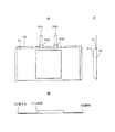
まず、図10Aに示すように、電池50を包みこむようにして硬質ラミネートフィルム41を曲げ、電池50の上面で硬質ラミネートフィルム41の端部が合うようにする。
次いで、電池50の上面及び底面からヒータブロックをあて、熱接着層74の樹脂材料が溶融する程度の温度で加圧しながら加熱する。樹脂材料は溶融して接着剤となり、硬質ラミネートフィルム41と電池50とを接着する。この際、軟質ラミネートフィルム57の外装層62が溶融しないようにする。これにより、断面を図10Bに示す電池アセンブリ45が作製される。
Here, the manufacturing method of the battery assembly will be described with reference to the drawings again. The exterior material composed of the
First, as shown in FIG. 10A, the
Next, a heater block is applied from the upper surface and the bottom surface of the
ヒータブロックの温度は熱接着層74の樹脂材料により変化するが、熱接着層の樹脂材料の溶融温度以上であり、軟質ラミネートフィルム57の外装層62を構成する材料の溶融温度よりも低い温度とする。これにより、軟質ラミネートフィルム57の外装層62を構成する樹脂材料を溶融させることなく接着することができる。
なお、粘着剤などによっても接合ないし接着させることができるが、熱を加えた接合の方が、連続的にかかる引き剥がし応力に対する耐性を高くできる。
Although the temperature of the heater block varies depending on the resin material of the
In addition, although it can join or adhere | attach also with an adhesive etc., the direction to which heat | fever applied can make the tolerance with respect to such peeling stress continuously high.
また、加熱温度が120℃を超える場合、電池素子に影響を与えることが考えられる。
例えば、電池素子に用いられるセパレータは、ポリエチレン(PE)を用いることが多いが、PEの融点が120℃程度であることから安全性や電池機能の低下を引き起こすことが考えられる。これより、ヒータブロックの温度は、110℃程度を上限として加熱する。
Moreover, when heating temperature exceeds 120 degreeC, it is possible to influence a battery element.
For example, polyethylene (PE) is often used as the separator used in the battery element, but since the melting point of PE is about 120 ° C., it is considered that safety and battery function are lowered. Thus, the heater block is heated to an upper limit of about 110 ° C.
なお、上述のように、本実施形態では、電池素子59を軟質ラミネートフィルム57に封入する際に脱気を行っており、この結果、電極とセパレーター間を大気圧の力で固定されるので、電池素子59全体を構造体して一体感のあるものとしている。
更に、電極、セパレーター間を固体状の非水電解質で連結させることによって、落下の衝撃に対し、電池素子の巻きズレや積層ズレといった現象が起こりにくい構造体に強化することができる。
As described above, in the present embodiment, deaeration is performed when the
Furthermore, by connecting the electrode and the separator with a solid non-aqueous electrolyte, it is possible to reinforce the structure in which a phenomenon such as winding deviation or stacking deviation of the battery element hardly occurs against the impact of dropping.
更にこれら素子を封止する際に脱気することで、軟質ラミネートフィルム57は大気圧により電池素子59に密着して固定され、単体時よりも外的な応力に強い耐性を得る。
また、本実施形態では、軟質ラミネートフィルムと硬質ラミネートフィルムを大気圧よりも強い接着強度で接合させることが可能であり、大気に打ち勝つので、軟質ラミネートフィルムが電池素子から浮き上がるような引き剥がし荷重が、硬質ラミネートフィルムにかからないような条件下では、硬質ラミネートフィルムも大気圧によって軟質ラミネートフィルム及び電池素子と一体化し、軽い落下時の挫屈などに対し耐性のある電池パック筐体として機能できる。
Further, by deaeration when sealing these elements, the
Further, in this embodiment, the soft laminate film and the hard laminate film can be bonded with an adhesive strength stronger than atmospheric pressure, and since it overcomes the atmosphere, there is a peeling load that causes the soft laminate film to lift from the battery element. Under conditions that do not cover the hard laminate film, the hard laminate film is also integrated with the soft laminate film and the battery element by atmospheric pressure, and can function as a battery pack housing that is resistant to buckling during a light drop.
なお、硬質ラミネートフィルムは図10で示すような構成だけでなく、図11〜図15に示すような構成としてもよい。
硬質ラミネートフィルムの熱接着層74を溶融させ、軟質ラミネートフィルムの外装層62が溶融しないようにすることは同様である。
In addition, a hard laminate film is good also as not only a structure as shown in FIG. 10 but a structure as shown in FIGS.
It is the same that the
図11A及び図11Bは、硬質ラミネートフィルム41を、電池50の底面部を覆うように設けて電池アセンブリ45とした構成であり、電池アセンブリ45の上面部に硬質ラミネートフィルム41の合わせ目が設けられる。なお、図10の電池アセンブリは、サイド部を丸くなるように成型しているのに対し、図11の電池アセンブリは断面が略長方形形状となるようになされている。
11A and 11B show a configuration in which the
図12A及び図12Bは、硬質ラミネートフィルム41を、電池50の一方のサイド部を覆うように設けて電池アセンブリ45とした構成であり、電池アセンブリ45の一方のサイド部に硬質ラミネートフィルム41の合わせ目が設けられる。
12A and 12B show a configuration in which the
図13A及び図13Bは、2枚の硬質ラミネートフィルム41を、電池50の両サイド部を覆うように設けて電池アセンブリ45とした構成であり、電池アセンブリ45の上面部及び底面部に硬質ラミネートフィルム41の合わせ目が設けられる。
13A and 13B show a configuration in which two
図14A及び図14Bは、2枚の硬質ラミネートフィルム41を、電池50の上面部及び底面部をそれぞれ覆うように設けて電池アセンブリ45とした構成であり、電池アセンブリ45の両サイド部に硬質ラミネートフィルム41の合わせ目が設けられる。
14A and 14B show a configuration in which two
図15A及び図15Bは、電池50のボトム部を包み込むように硬質ラミネートフィルム41を折り曲げて電池アセンブリ45とした構成である。なお、図15Bは電池アセンブリ45の側面から見た断面図である。
15A and 15B show a configuration in which the
[電池パックの作製]
次いで、回路基板44を正極端子55a及び負極端子55bと接続する(図3参照)。
所定の形状に成型された電池アセンブリ45のトップ部から導出された正極端子55a及び負極端子55bと、回路基板44上にあらかじめマウントされた保護回路とを抵抗溶接、超音波溶接等により固着する。
電池素子59と接続された回路基板44は、あらかじめ成型された上部ホルダー42a及び下部ホルダー42bを嵌合してなるトップカバー42に挿入される。
[Production of battery pack]
Next, the circuit board 44 is connected to the
The
The circuit board 44 connected to the
回路基板44には、ヒューズ、PTC、サーミスタ等の温度保護素子を含む保護回路の他、電池パックを識別するためのID、抵抗等がマウントされ、更に複数個の接点部が形成されている。保護回路には、二次電池の監視とFET(Field Effect Transistor)の制御を行うIC及び、充放電制御FETを含んだ保護回路にも適用される。 The circuit board 44 is mounted with a protection circuit including a temperature protection element such as a fuse, PTC, and thermistor, an ID for identifying the battery pack, a resistor, and the like, and a plurality of contact portions. The protection circuit is also applied to a protection circuit including an IC for monitoring a secondary battery and controlling a field effect transistor (FET) and a charge / discharge control FET.
PTC素子は電池素子と直列に接続され、電池の温度が設定温度に比して高くなると、電気抵抗が急激に高くなって電池に流れる電流を実質的に遮断する。ヒューズや、サーミスタも電池素子と直列に接続され、電池の温度が設定温度より高くなると、電池に流れる電流を遮断する。
また、二次電池の監視とFETの制御を行うIC及び、充放電制御FETを含んだ保護回路は、二次電池の端子電圧が4.3V〜4.4Vを超えると、発熱・発火など危険な状態になる可能性があるので、二次電池の電圧を監視し、4.3V〜4.4Vを越えると充電制御FETをオフし、充電を禁止する。
さらに二次電池の端子電圧が放電禁止電圧以下まで過放電し、二次電池電圧が0Vになると二次電池が内部ショート状態となり再充電不可能となる可能性があるので、二次電池電圧を監視して放電禁止電圧を下回ると放電制御FETをオフし、放電を禁止する。
The PTC element is connected in series with the battery element, and when the temperature of the battery becomes higher than the set temperature, the electrical resistance increases rapidly and substantially interrupts the current flowing through the battery. A fuse and a thermistor are also connected in series with the battery element, and when the temperature of the battery becomes higher than the set temperature, the current flowing through the battery is cut off.
In addition, ICs that monitor secondary batteries and control FETs, and protection circuits that include charge / discharge control FETs, can generate heat and fire when the secondary battery terminal voltage exceeds 4.3V to 4.4V. Therefore, if the voltage of the secondary battery exceeds 4.3V to 4.4V, the charge control FET is turned off and charging is prohibited.
Furthermore, if the secondary battery terminal voltage is overdischarged to below the discharge prohibition voltage and the secondary battery voltage becomes 0V, the secondary battery may be shorted internally and cannot be recharged. If it is monitored and falls below the discharge inhibition voltage, the discharge control FET is turned off to inhibit discharge.
電池アセンブリ45と接合した回路基板44は、上下から予め射出成型により成型された上部ホルダー42a及び下部ホルダー42bで覆われ、下部ホルダー42bを上部ホルダー42aに嵌合することによりトップカバー42に収容される。
次いで、下部ホルダー42bが電池アセンブリ45に近い位置となるようにトップカバー42の方向を変え、、正極端子55a及び負極端子55bが電池アセンブリ45内で屈曲するようにして電池アセンブリ45のトップ部の開口部にトップカバー42を嵌合する。
The circuit board 44 joined to the
Next, the direction of the top cover 42 is changed so that the lower holder 42b is close to the
次いで、ヒータヘッドによりトップカバー42と電池アセンブリ45との嵌合部を加熱し、トップカバー42と電池アセンブリ45とを熱融着する。このとき、ヒータヘッドの温度は、電池アセンブリ形成時よりも高く、シーラント層73の樹脂材料の溶融温度以上とされ、トップカバー42は、熱接着層74ではなくシーラント層73と接着される。
Next, the fitting portion between the top cover 42 and the
硬質ラミネートフィルム41と電池50とを接着する際に加熱された熱接着層74は、トップカバー42が嵌合される際にトップカバー42で押され、電池アセンブリ45の奥に移動する。
上述のとおり、熱接着層74にはシーラント層73に比して低い溶融温度の樹脂材料を用いているため、硬質ラミネートフィルム41と電池50との接着の際には、熱接着層74のみが溶融することになる。このため、トップカバー42と接着するために用いるシーラント層73を移動させることなく、熱接着層74を移動でき、シーラント層73を露出させることができる。
The
As described above, since the resin material having a lower melting temperature than the
このとき、必要に応じて、電池50とトップカバー42との間隙に接着剤又は温めた樹脂材料(ホットメルト樹脂)を注入してもよい。この場合、予めトップカバー42に接着剤・ホットメルト樹脂の注入口を設ける。
接着剤又はホットメルト樹脂を注入することにより、電池アセンブリ45とトップカバー42との接着性がより向上する。ただし、ホットメルト樹脂を注入する場合は、回路基板44が熱で変形したり損傷しないように対応が必要である。
At this time, an adhesive or a warmed resin material (hot melt resin) may be injected into the gap between the
By injecting the adhesive or the hot melt resin, the adhesion between the
続いて、電池アセンブリ45のボトム部にリアカバー43を嵌合し、ヒータヘッドによりリアカバー43と電池アセンブリ45との嵌合部を加熱してリアカバー43と電池アセンブリ45とを熱融着する。この場合もトップカバー42の場合と同様に、リアカバー43が嵌合される際に熱接着層74がリアカバー43で押されて電池アセンブリ45奥に移動し、露出したシーラント層73とリアカバー43とが接着される。
Subsequently, the rear cover 43 is fitted to the bottom portion of the
このとき、トップカバー42の場合と同様に、必要に応じて電池50とリアカバー43との間隙に接着剤やホットメルト樹脂を注入してもよい。この場合も、予めリアカバー43に接着剤・ホットメルト樹脂の注入口を設けておく。また、トップカバー42とリアカバー43の嵌合及び熱融着工程を同時に行ってもよい。
At this time, as in the case of the top cover 42, an adhesive or hot melt resin may be injected into the gap between the
また、リアカバー43については、予め成型された部材を用いるだけでなく、電池アセンブリ45を金型に設置し、ボトム部にホットメルト樹脂を流し込むことにより、電池アセンブリ45と一体に成型する方法を用いることも可能である。
For the rear cover 43, not only a pre-molded member is used, but a method of molding the
このように、金属箔71の内側に、シーラント層73としてトップカバー42及びリアカバー43と接着性のよい樹脂材料を設け、さらにシーラント層73の内側に硬質ラミネートフィルム41の外装層62と接着性がよく、シーラント層73よりも溶融温度の低い樹脂材料を用いた熱接着層74を設けることにより、電池50と硬質ラミネートフィルム41、電池アセンブリ45とトップカバー42及びリアカバー43をそれぞれ良好に接着することができる。このため、破損しにくい電池パック40構成となる。
As described above, the resin material having good adhesiveness with the top cover 42 and the rear cover 43 is provided as the
最後に、電池パック45の一部に生じる硬質ラミネートフィルム41の合わせ目部分を覆うように、製品ラベルを貼着することにより、図2に示すような電池パック40となる。なお、製品ラベル46は必要に応じて設ければよい。
Finally, by sticking a product label so as to cover the joint portion of the
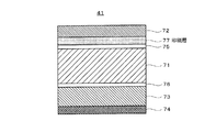
また、製品ラベル46を設ける替わりに、硬質ラミネートフィルム41自体に印刷、焼付け塗装等を施す方法を用いることもできる。例えば、図16に示すように、硬質ラミネートフィルム41の外装層72の内側面(金属箔側面)に所望の図柄、文字等を印刷する印刷層77を設け、外装層72を通して印刷が見えるようにしてもよい。
この場合、図柄、文字等は反転して印刷する。また、図17に示すように、金属箔71の外側面にレーザ等による焼付け塗装78を施してもよい。この場合、硬質ラミネートフィルムの外装層72及び外装層72と金属箔71を接着する接着層を設けず、焼付け塗装78を施した金属箔71が露出するようにすることができる。
Further, instead of providing the product label 46, a method of performing printing, baking coating or the like on the
In this case, symbols, characters, etc. are printed in reverse. In addition, as shown in FIG. 17, the outer surface of the
このようにして電池パック40を作製することにより、電池パック40の対外部衝撃強度を確保することができる。 By producing the battery pack 40 in this manner, the external impact strength of the battery pack 40 can be ensured.
また、外装に硬質ラミネートフィルムのような金属材を用いることにより、ラミネート外装電池であっても釘刺し時の発熱箇所が電池表面となり、また放熱が促進されるため、電池内部の発熱を抑制することができる。このため、より安全な電池パックを提供することができる。 In addition, by using a metal material such as a hard laminate film for the exterior, even in the case of a laminate exterior battery, the heat generation part at the time of nail penetration becomes the battery surface, and the heat dissipation is promoted, so the heat generation inside the battery is suppressed. be able to. For this reason, a safer battery pack can be provided.
(実施形態2)
この実施形態2では、外装材として3層構造の硬質ラミネートフィルムを用いる電池パックについて説明する。
本実施形態による電池パックのパック構成は、図2及び図3で示す上述の実施形態1と同様である。また、電池素子及び電池についても、実施形態1と同様であるため、説明を省略する。
(Embodiment 2)
In Embodiment 2, a battery pack using a three-layer hard laminate film as an exterior material will be described.
The pack configuration of the battery pack according to the present embodiment is the same as that of the above-described first embodiment shown in FIGS. Further, the battery element and the battery are the same as those in the first embodiment, and thus the description thereof is omitted.
[電池アセンブリの作製]
電池50を、図18で示す3層構造の硬質ラミネートフィルム80で外装し、電池アセンブリを作製する。まず、硬質ラミネートフィルム80の構成について説明する。
[Production of battery assembly]
The
図18に示すように、実施形態2における硬質ラミネートフィルム80は、符号81で示される金属箔が、樹脂フィルムからなる外装層82及び熱接着層83に挟まれた、防湿性、絶縁性を有する多層フィルムからなる。
なお、金属箔81及び外装層82としては、第1の実施形態と同様の材料を用いることができる。
As shown in FIG. 18, the
In addition, as the metal foil 81 and the exterior layer 82, the same material as in the first embodiment can be used.
熱接着層83は、別に接着用部材を設けることなく、軟質ラミネートフィルム57で外装された電池50と硬質ラミネートフィルム80とを接着するためのものである。
この実施形態2では、電池50の外装層62であるNy、PET,PEN等の樹脂、及びトップカバー42及びリアカバー43の材料となるPP等の樹脂のそれぞれとの接着性に優れた反応性に富む材料を熱接着層83として用いることにより、実施形態1で設けたシーラント層73を設けることなく電池パックを構成することができる。
The thermal bonding layer 83 is for bonding the
In the second embodiment, the reactivity is excellent in adhesiveness with each of the resin such as Ny, PET, and PEN that is the outer layer 62 of the
このような材料として、具体的には、酸変成したポリプロピレン、アイオノマー樹脂、エチレン酢酸ビニルコポリマー、エチレンアクリル酸コポリマー、アクリル酸エチルコポリマー、アクリル酸メチルコポリマー、メタクリル酸コポリマー、メタクリル酸メチルコポリマー、ポリアクリロニトリル、エチレンビニルアルコール樹脂、ポリアミド及びポリエステル等を用いることができ、中でも酸変成したポリプロピレン、アイオノマー樹脂及びエチレンビニルアルコール樹脂が特に好適である。これらの材料は、ホットメルト剤、フィルムもしくは耐候性の粘着剤として用いることができる。 Specific examples of such materials include acid-modified polypropylene, ionomer resins, ethylene vinyl acetate copolymers, ethylene acrylic acid copolymers, ethyl acrylate copolymers, methyl acrylate copolymers, methacrylic acid copolymers, methyl methacrylate copolymers, polyacrylonitrile. , Ethylene vinyl alcohol resin, polyamide, polyester, and the like can be used, and acid-modified polypropylene, ionomer resin, and ethylene vinyl alcohol resin are particularly preferable. These materials can be used as a hot melt agent, a film, or a weather-resistant adhesive.
実施形態2における硬質ラミネートフィルム80では、熱接着層83は、25〜50μm程度の厚さで設ける。また、金属箔81及び外装層82は、実施形態1と同等の厚さとしてよい。実施形態1における硬質ラミネートフィルム41の熱接着層74の厚さは1〜5μmであったが、実施形態2では熱接着層83を厚めに構成することにより、熱接着層83自身にクッション性を持たせ、接着性を高めている。
In the
このような硬質ラミネートフィルム80からなる外装材を、電池50に接着する。実施形態1と同様に、電池50を包みこむようにして硬質ラミネートフィルム80を曲げ、電池50上面で硬質ラミネートフィルム80の端部が合うようにする。
次いで、電池50の上面及び底面からヒータブロックをあて、熱接着層83の樹脂材料が溶融する程度の温度で加熱するとともに加圧する。樹脂材料は溶融して接着剤となり、硬質ラミネートフィルム80と電池50とを接着する。この際、軟質ラミネートフィルムの外装層62が溶融しないようにすることは実施形態1と同様である。これにより、電池アセンブリ90が作製される。
An exterior material made of such a
Next, a heater block is applied from the top and bottom surfaces of the
ヒータブロックの温度は熱接着層の樹脂材料により変化するが、熱接着層83の樹脂材料の溶融温度以上であればよい。また、加熱温度が120℃を超える場合、電池素子59に影響を与えることが考えられる。このような観点から、ヒータブロックの温度は、110℃程度を上限として加熱するのが望ましい。
Although the temperature of the heater block varies depending on the resin material of the thermal bonding layer, it may be higher than the melting temperature of the resin material of the thermal bonding layer 83. In addition, when the heating temperature exceeds 120 ° C., it is considered that the
[電池パックの作製]
次いで、回路基板44を正極端子55a及び負極端子55bと接続する。回路基板44及び正極端子55a及び負極端子55bと回路基板44との接続方法は、実施形態1と同様であるため、説明を省略する。
[Production of battery pack]
Next, the circuit board 44 is connected to the
回路基板44が収容されたトップカバー42は、電池アセンブリ90のトップ側開口部に嵌合される。次いで、ヒータヘッドによりトップカバー42の嵌合部を加熱し、トップカバー42と電池アセンブリ90とを熱融着する。
本実施形態では、熱接着層83の樹脂材料としてトップカバー42及びリアカバー43との接着性に優れた樹脂材料を用いるため、トップカバー42は熱接着層83と接着される。また、リアカバー43もトップカバー42と同様に電池アセンブリ90と接着することができる。
The top cover 42 in which the circuit board 44 is accommodated is fitted into the top side opening of the
In the present embodiment, since a resin material excellent in adhesiveness to the top cover 42 and the rear cover 43 is used as the resin material for the thermal bonding layer 83, the top cover 42 is bonded to the thermal bonding layer 83. Further, the rear cover 43 can be bonded to the
このとき、必要に応じて、電池50とトップカバー42との間隙に接着剤もしくは温めた樹脂材料(ホットメルト樹脂)を注入してもよい。この場合、予めトップカバー及びリアカバーに接着剤・ホットメルト樹脂の注入口を設ける。接着剤もしくはホットメルト樹脂を注入することにより、電池アセンブリ90とトップカバー42及びリアカバー43との接着性がより向上する。ただし、トップカバー42からホットメルト樹脂を注入する場合は、回路基板が熱で変形したり損傷しないように対応が必要である。
At this time, an adhesive or a warmed resin material (hot melt resin) may be injected into the gap between the
また、リアカバー43は予め成型された部材を用いるだけでなく、電池アセンブリ90を金型に設置し、ボトム部にホットメルト樹脂を流し込むことにより、電池アセンブリ90と一体に成型する方法を用いることも可能である。
Further, the rear cover 43 is not only made of a pre-molded member, but may be a method in which the
以上、実施形態2による3層構造の硬質ラミネートフィルム80を外装材として用いた電池パック90について説明した。
実施形態1の電池パックが有する落下時などにおける優れた機能の外、熱接着層83に用いる樹脂材料を好適に選択することにより、シーラント層を設けなくても対外部衝撃強度を確保するとともに、耐浸水性や放熱性を充分に備えたより安全な電池パックを提供することができる。
The
In addition to the excellent function when the battery pack of
(実施形態3)
図19に、本発明の他の電池パックの一実施形態を示す。
図19A〜図19C及び図20A、図20Bは、本実施形態の電池パックにおける電池の製造途中の構成を示す模式図である。
(Embodiment 3)
FIG. 19 shows an embodiment of another battery pack of the present invention.
19A to 19C and FIGS. 20A and 20B are schematic diagrams illustrating a configuration in the middle of manufacturing a battery in the battery pack of the present embodiment.
本実施形態では、凹部31aを有する軟質ラミネートフィルム31と硬質ラミネートフィルム32とを用い、凹部31aに電池素子35を収容するようにして、電池素子の主要部、即ち6面体をなす電池素子35の1つの主面を残した部位を軟質ラミネートフィルム31で外装する(図20参照)。
次いで、硬質ラミネートフィルム32が電池素子35の残部、即ち電池素子35の1つの主面を、典型的には凹部31aの開口を覆うように配置し、軟質ラミネートフィルム31と硬質ラミネートフィルム32とが重なった電池素子35の周囲部分を封止する。この際、減圧下での熱融着により封止することは実施形態1と同様であり、かかる減圧下での熱融着によって、電池素子35は、軟質ラミネートフィルム31及び硬質ラミネートフィルム32と密着する。
In the present embodiment, a
Next, the
更に、図20Bに示すように、電池素子35を包み込むようにして硬質ラミネートフィルム32及び軟質ラミネートフィルム31を成型するが、本実施形態では、熱接着性樹脂テープ90を準備し、このテープ90を、折り返した軟質ラミネートフィルム31の外装層と電池素子35を被覆している軟質ラミネートフィルム31の外装層との間に配置して溶融させ、これら軟質ラミネートフィルム同士を接着させる。
これと同時に、硬質ラミネートフィルム32の熱接着層を溶融させ、折り返した軟質ラミネートフィルム31の熱接着層と接着させる。この際、軟質ラミネートフィルム31の外装層が溶融しないようにすることは実施形態1と同様である。なお、熱接着性樹脂テープ90には、基材が存在してよいのは勿論である。
Further, as shown in FIG. 20B, the
At the same time, the thermal adhesive layer of the
次いで、図示しない回路基板及び樹脂成型カバーを設けることにより、硬質ラミネートフィルム32が最外装となった電池パック30を作製することができる。このような電池パックは、体積効率が良く、高い電池強度を実現するものであるとともに、実施形態1の電池パックが有する落下時などにおける優れた機能をも有する。
Next, by providing a circuit board (not shown) and a resin molding cover, the battery pack 30 having the
(実施形態4)
図21は、本発明の他の電池パックの他の実施形態を示し、製造過程の状態を示す断面図である。
本実施形態の電池パックも、実施形態3の電池パックと同様の構成を有するが、軟質ラミネートフィルム31の両サイドが短くなっている(図21A)。
(Embodiment 4)
FIG. 21 is a cross-sectional view showing another embodiment of the battery pack of the present invention and showing the state of the manufacturing process.
The battery pack of this embodiment also has the same configuration as that of the battery pack of Embodiment 3, but both sides of the
実施形態3と同様に、電池素子35を周囲部分を封止し、次いで、図21Bに示すように、電池素子35を包み込むようにして硬質ラミネートフィルム32及び軟質ラミネートフィルム31を成型するが、本実施形態では、熱接着性樹脂テープ90を準備し、このテープ90を、折り返した硬質ラミネートフィルム32の外装層と電池素子35を被覆している軟質ラミネートフィルム31の外装層との間に配置して溶融させ、両者フィルムを接着させる。この際、硬質ラミネートフィルム32の外装層を溶融させる一方で、軟質ラミネートフィルム31の外装層が溶融しないようにすることは実施形態1と同様である。なお、熱接着性樹脂テープ90には、基材が存在してよいのは勿論である。
As in the third embodiment, the
本実施形態の電池パックも実施形態1の電池パックが有する落下時などにおける優れた機能を有する。
なお、本実施形態では、熱接着性樹脂テープ90の代わりに、いわゆる両面テープを用いることも可能であり、この場合は低温での接着が可能になる。
The battery pack of this embodiment also has an excellent function when the battery pack of
In the present embodiment, a so-called double-sided tape can be used instead of the heat-
(実施形態5)
図22は、本発明の他の電池パックの更に他の実施形態を示し、製造過程の状態を示す断面図である。
本実施形態の電池パックも、実施形態3の電池パックと同様の構成を有するが、軟質ラミネートフィルム31の両サイドが短くなっている(図22A)。
(Embodiment 5)
FIG. 22 is a cross-sectional view showing still another embodiment of another battery pack of the present invention and showing the state of the manufacturing process.
The battery pack of this embodiment also has the same configuration as the battery pack of Embodiment 3, but both sides of the
実施形態3と同様に、電池素子35を周囲部分を封止し、次いで、図22Bに示すように、電池素子35を包み込むようにして硬質ラミネートフィルム32及び軟質ラミネートフィルム31を成型するが、本実施形態では、折り返した硬質ラミネートフィルム32の熱接着層を溶融させ、これと電池素子35を被覆している軟質ラミネートフィルム31の外装層を接着させる。この際、硬質ラミネートフィルム32の熱接着層を溶融させる一方で、軟質ラミネートフィルム31の外装層が溶融しないようにすることは実施形態1と同様である。
As in the third embodiment, the
本実施形態の電池パックも、実施形態1の電池パックが有する落下時などにおける優れた機能を有する。
なお、本実施形態では、 折り返した硬質ラミネートフィルム32の外装層と電池素子35を被覆している軟質ラミネートフィルム31の外装層との間に、アクリルエステル系、シリコーン系、ラテックス系などの粘着剤を用いることができ、この場合は低温での接着が可能になる。
The battery pack of this embodiment also has an excellent function when the battery pack of
In the present embodiment, an acrylic ester-based, silicone-based, latex-based adhesive or the like is provided between the folded outer layer of the
以下、本発明を実施例及び比較例により更に詳細に説明するが、本発明はこれら実施例に限定されるものではない。 EXAMPLES Hereinafter, although an Example and a comparative example demonstrate this invention further in detail, this invention is not limited to these Examples.
(実施例1−1〜23−5、比較例1及び2)
以下の表1〜表4に示す仕様の電池パックを以上に説明した操作によって作製した。得られた各例の電池パックを以下の性能評価に供し、得られた結果を表5〜8に示した。
(Examples 1-1 to 23-5, Comparative Examples 1 and 2)
The battery packs having the specifications shown in Tables 1 to 4 below were produced by the operations described above. The obtained battery packs of the respective examples were subjected to the following performance evaluation, and the obtained results are shown in Tables 5 to 8.
(a)落下試験1
各実施例及び比較例の電池パックを1.5mの高さから10回自由な姿勢にて落下させた後、携帯機器に装填し違和感なく装填可能か、機能劣化無く充電と使用が可能か確認した。発電要素の素子、外装の設計上、ともに本来ダメージを追わない高さであり、パックとしても引き続き使用が可能であることが必要である。
(A)
After dropping the battery pack of each Example and Comparative Example from a height of 1.5 m 10 times in a free posture, confirm whether it can be loaded into a portable device without a sense of incongruity, or can be charged and used without functional deterioration did. Both the element of the power generation element and the exterior design must be of a height that does not inherently follow damage, and must be usable as a pack.
(b)落下試験2
各実施例及び比較例の電池パックを10mの高さから自由な姿勢にて落下させた後、携帯機器に装填不可能なこと。電池素子に損傷ないこと。電池外装に損傷なきこと。を確認する。
設計上電池内に外気が入り込まない限りはダメージが発生しない。外装は損傷を受ける可能性がある。パック筐体は衝撃を吸収し素子を衝撃から守ることが要求される。
本試験では電池パックが使用不可であっても電池本体、電池外装にダメージが無ければ合格、電池パックに不具合が無くても電池本体、電池外装に不具合が発生すると不合格とした。
(B) Drop test 2
The battery pack of each example and comparative example cannot be loaded into a portable device after dropping in a free posture from a height of 10 m. Do not damage the battery element. No damage to the battery exterior. Confirm.
As long as outside air does not enter the battery by design, no damage will occur. The exterior can be damaged. The pack housing is required to absorb the impact and protect the element from the impact.
In this test, even if the battery pack was unusable, the battery main body and the battery outer case were acceptable, and the battery main body and the battery outer case were acceptable.
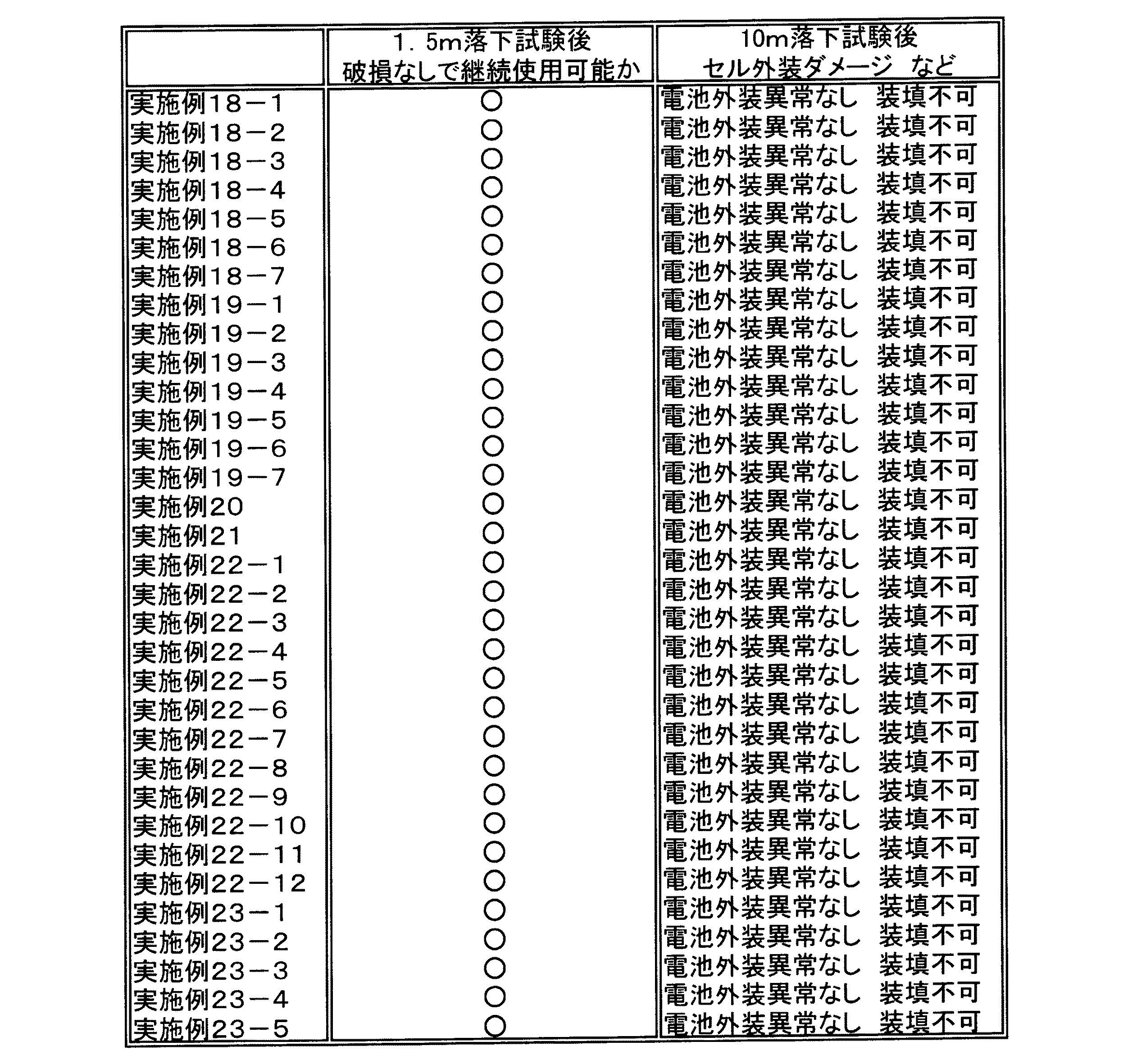
表1〜4に示した各実施例及び各比較例の電池パックの仕様について簡単に説明する。
実施例1群は、硬質外装材に種々の材料種を採用したものである。また、実施例2は実施例1−1における硬質外装材の金属層に種々の材料種を採用したもの、実施例3は実施例1−6において硬質外装材の外装層の厚みを大きくしたもの、実施例4は実施例3における硬質外装材の金属層をステンレスにして厚みを大きくしたもの、実施例5群は実施例1−1における硬質外装材の接着剤層に種々の材料を適用したもの、である(表1参照)。
The specifications of the battery packs of Examples and Comparative Examples shown in Tables 1 to 4 will be briefly described.
Example 1 group employs various material types for the hard exterior material. Also, Example 2 employs various material types for the metal layer of the hard exterior material in Example 1-1, and Example 3 increases the thickness of the exterior layer of the hard exterior material in Example 1-6. In Example 4, the metal layer of the hard exterior material in Example 3 was made of stainless steel to increase the thickness, and in Example 5 group, various materials were applied to the adhesive layer of the hard exterior material in Example 1-1. (See Table 1).
一方、比較例1は、軟質外装材の外装層及び硬質外装材の接着層の双方を溶融させたものであるが、10m落下試験後に電池パックとしては機器に装着可能であったが、軟質外装材が伸ばされて損傷を負っており、後日機器内で電池パックが膨れた(表5参照)。
また、比較例2は、電池素子を封止する際に軟質外装材内を脱着せずに封止したものであるが、電池素子と軟質外装材との密着性が不十分であり、電池素子と軟質外装材との一体感に欠け、1.5m落下試験時に強度不足のために変形し、機器への装着も不可能であった。また、10m落下試験時には電池素子及び外装材がともに損傷を受け、発熱やガス発生を引き起こした(表5参照)。
On the other hand, Comparative Example 1 was obtained by melting both the exterior layer of the soft exterior material and the adhesive layer of the hard exterior material, but it could be attached to the device as a battery pack after a 10 m drop test. The material was stretched and damaged, and the battery pack swelled in the equipment at a later date (see Table 5).
In Comparative Example 2, the battery element is sealed without detaching the inside of the soft exterior material, but the adhesion between the battery element and the soft exterior material is insufficient, and the battery element Lacked a sense of unity with the soft exterior material, deformed due to insufficient strength during a 1.5 m drop test, and could not be attached to equipment. Also, during the 10 m drop test, both the battery element and the exterior material were damaged, causing heat generation and gas generation (see Table 5).
なお、実施例7群は硬質外装材の外装層に種々の材料種を適用して複合層を形成したもの、実施例8群は実施例7−1における硬質外装材の金属層、軟質外装材の金属層にそれぞれ所定の厚みを有する異なる同種の材料種を用いたもの、実施例9群は実施例7−1における硬質外装材の金属層の厚みを300μmにし、金属層の合計厚みを335μmとしたもの、実施例10群は実施例7−1における複合層と接着テープに種々の材料を適用したもの、実施例11群は実施例7−1における軟質外装材の外装層に種々の材料を用いたものである(表2参照)。 In Example 7, the composite layer was formed by applying various material types to the exterior layer of the hard exterior material. Example 8 group was the metal layer of the hard exterior material in Example 7-1, and the soft exterior material. In Example 9 group, the thickness of the metal layer of the hard exterior material in Example 7-1 is set to 300 μm, and the total thickness of the metal layers is set to 335 μm. Example 10 group was obtained by applying various materials to the composite layer and the adhesive tape in Example 7-1. Example 11 group was produced by applying various materials to the exterior layer of the soft exterior material in Example 7-1. (See Table 2).
また、表3において、実施例12群は硬質外装材の外装層に種々の材料種を適用したもの、実施例13群は実施例12−1における硬質外装材の金属層に種々の材料種を適用したもの、実施例14は実施例12−6における硬質外装材の外装層の厚みを大きくしたもの、実施例15は実施例14における硬質外装材の金属層の厚みを大きくしたもの、実施例16群は実施例12−1における接着テープに種々の材料種を適用したもの、実施例17群は実施例12−1における軟質外装材の外装層に種々の材料種を適用したものである。 Moreover, in Table 3, Example 12 group applied various material types to the exterior layer of the hard exterior material, and Example 13 group applied various material types to the metal layer of the hard exterior material in Example 12-1. What was applied, Example 14 was obtained by increasing the thickness of the exterior layer of the hard exterior material in Example 12-6, Example 15 was obtained by increasing the thickness of the metal layer of the hard exterior material in Example 14, Example Group 16 is obtained by applying various material types to the adhesive tape in Example 12-1, and Example 17 group is obtained by applying various material types to the exterior layer of the soft exterior material in Example 12-1.
更に、表4において、実施例18群は硬質外装材の外装層に種々の材料種を適用したもの、実施例19群は実施例18−1における硬質外装材の金属層に種々の材料種を適用したもの、実施例20は実施例18−6における硬質外装材の外装層の厚みを大きくしたもの、実施例21は実施例20における硬質外装材の金属層の厚みを大きくしたもの、実施例22群は実施例18−1における硬質外装材の接着層に種々の材料種を適用したもの、実施例23群は実施例18−1における軟質外装材の外装層に種々の材料種を適用したものである。 Furthermore, in Table 4, Example 18 group applied various material types to the exterior layer of the hard exterior material, and Example 19 group applied various material types to the metal layer of the hard exterior material in Example 18-1. What was applied, Example 20 was obtained by increasing the thickness of the exterior layer of the hard exterior material in Example 18-6, Example 21 was obtained by increasing the thickness of the metal layer of the hard exterior material in Example 20, Example Group 22 applied various material types to the adhesive layer of the hard exterior material in Example 18-1, and Example 23 group applied various material types to the exterior layer of the soft exterior material in Example 18-1. Is.
表5〜表8より、各実施例の電池パックは、ともに1.5m落下試験では電池も電池外装も電池パックも不具合なく使用可能であることが分かる。
また、各実施例の電池パックは、ともに10m落下試験では電池パックの外装は変形し使用不可であったが電池本体や外装には不具合なく、ガス発生などの現象はなかった。
From Tables 5 to 8, it can be seen that the battery packs of the respective examples can be used without any defects in the battery, the battery exterior, and the battery pack in the 1.5 m drop test.
In each of the battery packs of each example, the exterior of the battery pack was deformed and could not be used in the 10-m drop test, but the battery body and the exterior were not defective and there was no phenomenon such as gas generation.
1…電池、2a…正極端子、2b…負極端子、31…軟質ラミネートフィルム、32…硬質ラミネートフィルム、35…電池素子、40…電池パック、41,80…硬質ラミネートフィルム、42…トップカバー、42a…上部ホルダー、42b…下部ホルダー、43…リアカバー、44…回路基板、45…電池アセンブリ、46…製品ラベル、50…電池、51…正極、52…負極、53a,53b…セパレータ、 55a・・・正極端子、55b…負極端子、57…軟質ラミネートフィルム、57a…凹部、59…電池素子、61,71,81…金属層、62,72,82…外装層、63,73…シーラント層、64,65,75,76,84,85…接着剤層、74…接着層、83…熱接着層、77…印刷層、78…焼付け塗装、90…熱接着性樹脂テープ
DESCRIPTION OF
Claims (9)
熱接着層、金属層及び外装層を順次積層した構造を有するラミネートフィルムから成り、上記電池素子の主要部を外装する軟質外装材と、
熱接着層、金属層及び外装層を順次積層した3層構造を有するラミネートフィルムから成り、上記電池素子の残部と上記軟質外装材を外装する硬質外装材と、
接着部材と、
上記正極と負極の電極端子を外部に導出したまま、上記電池素子の周囲に沿って上記軟質外装材と上記硬質外装材とを接合させて上記電池素子を封止して成る非水電解質二次電池と、
上記硬質外装材に収容され上記非水電解質二次電池の電圧及び電流を制御可能な保護回路基板と、を備え、
上記電池素子と上記軟質外装材とが密着しており、
上記電池素子の周囲部分において、上記軟質外装材と上記硬質外装材とが、互いに対向する上記軟質外装材の熱接着層および上記硬質外装材の熱接着層が融解することにより、接合し、
上記軟質外装材の外装層は、その熱伝導率が1Wm-1K-1以下で、且つ上記硬質外装材の熱接着層よりも溶融温度が高く、
上記硬質外装材を、上記電池素子を包み込むようにして折り返し、折り返した上記硬質外装材の端部と、上記電池素子の主要部を外装する上記軟質外装材の表面とが、上記軟質外装材の外装層が融けず且つ上記接着部材が融けることにより接合されている電池パック。 A battery element comprising a positive electrode and a negative electrode wound or laminated via a separator, and having a non-aqueous electrolyte composition;
A soft exterior material comprising a laminate film having a structure in which a thermal adhesive layer, a metal layer and an exterior layer are sequentially laminated, and exteriors the main part of the battery element;
A laminate film having a three-layer structure in which a thermal adhesive layer, a metal layer, and an exterior layer are sequentially laminated, and a hard exterior material that sheathes the remainder of the battery element and the soft exterior material;
An adhesive member;
A non-aqueous electrolyte secondary formed by sealing the battery element by bonding the soft exterior material and the hard exterior material along the periphery of the battery element while the electrode terminals of the positive electrode and the negative electrode are led out to the outside. Battery,
A protective circuit board accommodated in the hard exterior material and capable of controlling the voltage and current of the non-aqueous electrolyte secondary battery,
The battery element and the soft exterior material are in close contact,
In the peripheral part of the battery element, the soft exterior material and the hard exterior material are joined by melting the thermal adhesive layer of the soft exterior material and the thermal adhesive layer of the hard exterior material facing each other,
The exterior layer of the soft exterior material has a thermal conductivity of 1 Wm −1 K −1 or less and a melting temperature higher than the thermal adhesive layer of the hard exterior material,
The hard exterior material is folded back so as to enclose the battery element, and the end of the folded hard exterior material and the surface of the soft exterior material covering the main part of the battery element are formed of the soft exterior material. A battery pack that is bonded by melting an exterior layer and melting the adhesive member.
上記硬質外装材の熱接着層が、エチレン酢酸ビニルコポリマー、エチレンアクリル酸コポリマー、アクリル酸エチルコポリマー、アクリル酸メチルコポリマー、メタクリル酸コポリマー、メタクリル酸メチルコポリマー、ポリアクリロニトリル、エチレンビニルアルコール樹脂、ポリアミド樹脂、ポリエステル樹脂、酸変成したポリプロピレン、アイオノマーから成る群より選ばれた少なくとも1種の樹脂から構成される層である請求項1に記載の電池パック。 The hard exterior material and the soft exterior material are thermally welded,
The heat-adhesive layer of the hard exterior material is an ethylene vinyl acetate copolymer, an ethylene acrylic acid copolymer, an ethyl acrylate copolymer, a methyl acrylate copolymer, a methacrylic acid copolymer, a methyl methacrylate copolymer, polyacrylonitrile, an ethylene vinyl alcohol resin, a polyamide resin, The battery pack according to claim 1, wherein the battery pack is a layer composed of at least one resin selected from the group consisting of a polyester resin, an acid-modified polypropylene, and an ionomer.
Priority Applications (1)
| Application Number | Priority Date | Filing Date | Title |
|---|---|---|---|
| JP2012002603A JP5482805B2 (en) | 2012-01-10 | 2012-01-10 | Battery pack |
Applications Claiming Priority (1)
| Application Number | Priority Date | Filing Date | Title |
|---|---|---|---|
| JP2012002603A JP5482805B2 (en) | 2012-01-10 | 2012-01-10 | Battery pack |
Related Parent Applications (1)
| Application Number | Title | Priority Date | Filing Date |
|---|---|---|---|
| JP2007104606A Division JP4954775B2 (en) | 2007-04-12 | 2007-04-12 | Battery pack |
Publications (2)
| Publication Number | Publication Date |
|---|---|
| JP2012094536A JP2012094536A (en) | 2012-05-17 |
| JP5482805B2 true JP5482805B2 (en) | 2014-05-07 |
Family
ID=46387597
Family Applications (1)
| Application Number | Title | Priority Date | Filing Date |
|---|---|---|---|
| JP2012002603A Active JP5482805B2 (en) | 2012-01-10 | 2012-01-10 | Battery pack |
Country Status (1)
| Country | Link |
|---|---|
| JP (1) | JP5482805B2 (en) |
Cited By (1)
| Publication number | Priority date | Publication date | Assignee | Title |
|---|---|---|---|---|
| KR20170090577A (en) * | 2016-01-29 | 2017-08-08 | 주식회사 엘지화학 | Battery Cell Comprising Cases of Different Heat Conductivity |
Families Citing this family (1)
| Publication number | Priority date | Publication date | Assignee | Title |
|---|---|---|---|---|
| CN108306387B (en) * | 2018-02-24 | 2021-05-11 | 濉溪野草信息科技有限公司 | Lithium cell group charge-discharge protection shield |
-
2012
- 2012-01-10 JP JP2012002603A patent/JP5482805B2/en active Active
Cited By (2)
| Publication number | Priority date | Publication date | Assignee | Title |
|---|---|---|---|---|
| KR20170090577A (en) * | 2016-01-29 | 2017-08-08 | 주식회사 엘지화학 | Battery Cell Comprising Cases of Different Heat Conductivity |
| KR102038308B1 (en) | 2016-01-29 | 2019-10-30 | 주식회사 엘지화학 | Battery Cell Comprising Cases of Different Heat Conductivity |
Also Published As
| Publication number | Publication date |
|---|---|
| JP2012094536A (en) | 2012-05-17 |
Similar Documents
| Publication | Publication Date | Title |
|---|---|---|
| JP4954775B2 (en) | Battery pack | |
| JP5228360B2 (en) | Battery pack | |
| JP4857742B2 (en) | Battery pack | |
| US7972722B2 (en) | Lead sealant film and non-aqueous electrolyte battery | |
| JP4458145B2 (en) | Battery pack and manufacturing method thereof | |
| JP5044934B2 (en) | Battery pack | |
| JP4797385B2 (en) | Battery pack | |
| JP4720186B2 (en) | Battery pack | |
| JP5482805B2 (en) | Battery pack | |
| JP5609894B2 (en) | Battery pack | |
| JP4639818B2 (en) | Battery pack | |
| JP5176374B2 (en) | Battery pack | |
| JP2008262801A (en) | Battery pack | |
| JP2011204604A (en) | Battery pack and method of manufacturing the same | |
| JP2008047331A (en) | Battery pack | |
| JP2012048938A (en) | Battery pack |
Legal Events
| Date | Code | Title | Description |
|---|---|---|---|
| A977 | Report on retrieval |
Free format text: JAPANESE INTERMEDIATE CODE: A971007 Effective date: 20131227 |
|
| TRDD | Decision of grant or rejection written | ||
| A01 | Written decision to grant a patent or to grant a registration (utility model) |
Free format text: JAPANESE INTERMEDIATE CODE: A01 Effective date: 20140121 |
|
| A61 | First payment of annual fees (during grant procedure) |
Free format text: JAPANESE INTERMEDIATE CODE: A61 Effective date: 20140203 |
|
| R151 | Written notification of patent or utility model registration |
Ref document number: 5482805 Country of ref document: JP Free format text: JAPANESE INTERMEDIATE CODE: R151 |
|
| R250 | Receipt of annual fees |
Free format text: JAPANESE INTERMEDIATE CODE: R250 |
|
| S111 | Request for change of ownership or part of ownership |
Free format text: JAPANESE INTERMEDIATE CODE: R313111 Free format text: JAPANESE INTERMEDIATE CODE: R313113 |
|
| R350 | Written notification of registration of transfer |
Free format text: JAPANESE INTERMEDIATE CODE: R350 |
|
| R360 | Written notification for declining of transfer of rights |
Free format text: JAPANESE INTERMEDIATE CODE: R360 |
|
| R371 | Transfer withdrawn |
Free format text: JAPANESE INTERMEDIATE CODE: R371 |
|
| S111 | Request for change of ownership or part of ownership |
Free format text: JAPANESE INTERMEDIATE CODE: R313113 |
|
| R360 | Written notification for declining of transfer of rights |
Free format text: JAPANESE INTERMEDIATE CODE: R360 |
|
| R250 | Receipt of annual fees |
Free format text: JAPANESE INTERMEDIATE CODE: R250 |
|
| R360 | Written notification for declining of transfer of rights |
Free format text: JAPANESE INTERMEDIATE CODE: R360 |
|
| R371 | Transfer withdrawn |
Free format text: JAPANESE INTERMEDIATE CODE: R371 |
|
| S111 | Request for change of ownership or part of ownership |
Free format text: JAPANESE INTERMEDIATE CODE: R313113 |
|
| R360 | Written notification for declining of transfer of rights |
Free format text: JAPANESE INTERMEDIATE CODE: R360 |
|
| R360 | Written notification for declining of transfer of rights |
Free format text: JAPANESE INTERMEDIATE CODE: R360 |
|
| R371 | Transfer withdrawn |
Free format text: JAPANESE INTERMEDIATE CODE: R371 |
|
| S111 | Request for change of ownership or part of ownership |
Free format text: JAPANESE INTERMEDIATE CODE: R313113 |
|
| R350 | Written notification of registration of transfer |
Free format text: JAPANESE INTERMEDIATE CODE: R350 |
|
| R250 | Receipt of annual fees |
Free format text: JAPANESE INTERMEDIATE CODE: R250 |