JP5482049B2 - screen - Google Patents
screen Download PDFInfo
- Publication number
- JP5482049B2 JP5482049B2 JP2009218619A JP2009218619A JP5482049B2 JP 5482049 B2 JP5482049 B2 JP 5482049B2 JP 2009218619 A JP2009218619 A JP 2009218619A JP 2009218619 A JP2009218619 A JP 2009218619A JP 5482049 B2 JP5482049 B2 JP 5482049B2
- Authority
- JP
- Japan
- Prior art keywords
- row
- recesses
- screen
- basic
- region
- Prior art date
- Legal status (The legal status is an assumption and is not a legal conclusion. Google has not performed a legal analysis and makes no representation as to the accuracy of the status listed.)
- Expired - Fee Related
Links
Images


Classifications
-
- G—PHYSICS
- G03—PHOTOGRAPHY; CINEMATOGRAPHY; ANALOGOUS TECHNIQUES USING WAVES OTHER THAN OPTICAL WAVES; ELECTROGRAPHY; HOLOGRAPHY
- G03B—APPARATUS OR ARRANGEMENTS FOR TAKING PHOTOGRAPHS OR FOR PROJECTING OR VIEWING THEM; APPARATUS OR ARRANGEMENTS EMPLOYING ANALOGOUS TECHNIQUES USING WAVES OTHER THAN OPTICAL WAVES; ACCESSORIES THEREFOR
- G03B21/00—Projectors or projection-type viewers; Accessories therefor
- G03B21/54—Accessories
- G03B21/56—Projection screens
- G03B21/60—Projection screens characterised by the nature of the surface
- G03B21/602—Lenticular screens
Landscapes
- Physics & Mathematics (AREA)
- General Physics & Mathematics (AREA)
- Overhead Projectors And Projection Screens (AREA)
- Projection Apparatus (AREA)
- Optical Elements Other Than Lenses (AREA)
Description
本発明は、プロジェクター等の投影装置から斜め入射する投射光を反射して投影画像を映し出すスクリーンに関する。 The present invention relates to a screen that reflects projection light incident obliquely from a projection device such as a projector and displays a projected image.
例えば、投影画像を反射させる反射スクリーンとして、下方からの斜め投射に対して正面側で観察可能にするものであって、スクリーン基板上に多数の凹部又は凸部を配置させるものが知られている(例えば、特許文献1参照)。このスクリーンでは、各凹部又は凸部の表面にプロジェクター等の投影機からの投影位置に応じて部分的に投射光の反射面を形成している。また、スクリーン基板上で鉛直方向に隣接する凹部又は凸部が、スクリーン基板の水平方向に関してずれた状態で配置されているため、斜め下方向からの光を多く反射させることができる。 For example, as a reflective screen that reflects a projected image, a screen that can be observed on the front side with respect to oblique projection from below, and that has a large number of concave portions or convex portions arranged on a screen substrate is known. (For example, refer to Patent Document 1). In this screen, a reflection surface for projection light is partially formed on the surface of each concave or convex portion according to the projection position from a projector such as a projector. Moreover, since the recessed part or convex part which adjoins a perpendicular direction on a screen board | substrate is arrange | positioned in the state shifted | deviated with respect to the horizontal direction of a screen board | substrate, many light from diagonally downward directions can be reflected.
しかしながら、特許文献1のようなスクリーンでは、プロジェクターの投射光とスクリーン法線との角度(入射角)がある一定以上になった場合、隣接する凹部間によって形成される突起により一部の投射光が遮られ、画像の局所的な減光のような視野欠損が生じる可能性がある。
However, in the screen as disclosed in
そこで、本発明は、投射光を遮る可能性を低減して、視野欠損の発生を抑制することができるスクリーンを提供することを目的とする。 Therefore, an object of the present invention is to provide a screen that can reduce the possibility of blocking projection light and suppress the occurrence of visual field defects.
上記課題を解決するため、本発明に係るスクリーンは、スクリーン基板と、スクリーン基板上に形成され、光を反射する複数の第1凹部を有する第1基本列と、スクリーン基板上で第1基本列に隣接して形成され、隣接する第1凹部と同一の個数の第2凹部を有する第1補助列とを有し、前記第1基本列と前記第1補助列とが交互に繰り返し配列される第1領域と、スクリーン基板上で第1領域よりも投射光のスクリーン基板への入射角が大きい位置に形成され、光を反射する複数の第3凹部を有する第2基本列と、スクリーン基板上で第2基本列に隣接して形成され、隣接する第3凹部より多い個数の第4凹部を有する第2補助列とを有し、前記第2基本列と前記第2補助列とが交互に繰り返し配列される第2領域と、を備える。 In order to solve the above problems, a screen according to the present invention includes a screen substrate, a first basic row formed on the screen substrate and having a plurality of first recesses for reflecting light, and a first basic row on the screen substrate. And the first auxiliary row having the same number of second concave portions as the adjacent first concave portions, and the first basic row and the first auxiliary row are alternately and repeatedly arranged. A first basic region, a second basic row formed on the screen substrate at a position where the incident angle of the projected light on the screen substrate is larger than that of the first region, and having a plurality of third recesses for reflecting the light; The second auxiliary row is formed adjacent to the second basic row and has a larger number of fourth concave portions than the adjacent third concave portion, and the second basic row and the second auxiliary row are alternately arranged. A second region that is repeatedly arranged.
上記スクリーンでは、第1及び第2基本列に加え、第1及び第2補助列を設けることにより、投射光の入射角が大きい場合でも、反射のための第1及び第3凹部の表面上に投射光を十分に入射させることができる。また、入射角が相対的に大きくなる第2領域において、第2基本列の第3凹部よりも第2補助列の第4凹部の個数を多くすることにより、隣接する第3及び第4凹部又は第4凹部相互によって形成される突起の高さを、第1領域と同様に第3及び第4凹部の個数が等しいとした場合の突起の高さよりも低くすることができる。これにより、第2領域において第1領域よりも投射光の入射角が大きくなっても、投射光が突起で遮られることを抑制でき、視野欠損を低減することができる。 In the above screen, by providing the first and second auxiliary rows in addition to the first and second basic rows, even when the incident angle of the projection light is large, on the surfaces of the first and third recesses for reflection. The projection light can be made sufficiently incident. Further, in the second region where the incident angle is relatively large, the number of the fourth recesses in the second auxiliary row is larger than the third recesses in the second basic row, so that the adjacent third and fourth recesses or The height of the protrusion formed by the fourth recesses can be made lower than the height of the protrusion when the number of the third and fourth recesses is the same as in the first region. Thereby, even if the incident angle of the projection light is larger in the second region than in the first region, the projection light can be prevented from being blocked by the protrusions, and the visual field defect can be reduced.
また、本発明の具体的な態様によれば、第1凹部及び第3凹部の表面の少なくとも一部分には反射部が形成され、前記反射部によって投射光を正面側に反射し、第1凹部及び第3凹部の表面の上記少なくとも一部以外と、第2凹部及び第4凹部の表面は、投射光を吸収し又は透過させる。第1凹部及び第3凹部のうち投射光を正面側に反射する少なくとも一部分以外の部分及び第2凹部及び第4凹部、すなわち投射光の入射を意図しない部分において、外光等を吸収等し、スクリーンで反射される画像のコントラストを向上させることができる。 Further, according to a specific aspect of the present invention, a reflective portion is formed on at least a part of the surfaces of the first concave portion and the third concave portion, the projection light is reflected to the front side by the reflective portion, and the first concave portion and The surfaces of the third recesses other than the above-described at least part and the surfaces of the second recesses and the fourth recesses absorb or transmit the projection light. In the first recess and the third recess, the portion other than at least a portion that reflects the projection light to the front side and the second recess and the fourth recess, that is, the portion that does not intend the incidence of the projection light, absorbs external light, etc. The contrast of the image reflected on the screen can be improved.
また、本発明の別の態様によれば、第1基本列、第1補助列、第2基本列、及び第2補助列は、いずれも少なくとも一部が円弧状である。この場合、第1基本列、第1補助列、第2基本列、及び第2補助列が円弧状であることにより、これらを構成する凹部の配列形状を投射光の入射位置に対応させることができ、投射光を適切な状態で反射させることができる。なお、スクリーン基板上において各列を交互に隙間なく設けることが望ましい。 According to another aspect of the present invention, at least a part of each of the first basic column, the first auxiliary column, the second basic column, and the second auxiliary column has an arc shape. In this case, since the first basic row, the first auxiliary row, the second basic row, and the second auxiliary row are arc-shaped, the arrangement shape of the concave portions constituting these can be made to correspond to the incident position of the projection light. The projected light can be reflected in an appropriate state. In addition, it is desirable to provide each row alternately on the screen substrate without a gap.
また、本発明の別の態様によれば、第2領域のうち第1領域との境界部分において、スクリーン基板に対して投射光の入射角が大きくなるほど同一の第3凹部に隣接する少なくとも2つの第4凹部間の距離が大きくなる。この場合、第2領域のうち第1領域との境界部分において互いに隣接する第4凹部間の距離を第1領域から離れるにしたがって除々に大きくしていくことにより、第1領域と第2領域との境界に切り替えムラが生じるのを防ぐことができる。ここで、1つの第3凹部と、この第3凹部に対して投射光の入射側に配置される少なくとも2つの第4凹部とを一組の単位として考える。また、切り替えムラは、両領域における凹部の異なる配置に起因して見かけの反射率が非一様に変化し、階段状やモアレ状といったパターンとして観察される光ムラを意味する。 According to another aspect of the present invention, at the boundary between the second region and the first region, at least two adjacent to the same third recess as the incident angle of the projection light increases with respect to the screen substrate. The distance between the fourth recesses is increased. In this case, by gradually increasing the distance between the fourth concave portions adjacent to each other at the boundary portion with the first region in the second region, the first region and the second region are increased. It is possible to prevent the occurrence of switching unevenness at the boundary. Here, one third recess and at least two fourth recesses disposed on the incident light incident side with respect to the third recess are considered as a set of units. Further, the switching unevenness means light unevenness in which the apparent reflectance changes nonuniformly due to different arrangements of the concave portions in both regions, and is observed as a pattern such as a staircase pattern or a moire pattern.
また、本発明の別の態様によれば、第2領域のうち第1領域との境界部分において、スクリーン基板に対して投射光の入射角が大きくなるほど第2補助列に含まれる第4凹部の個数が多くなる。この場合、第2領域のうち第1領域との境界部分で第4凹部の個数を第1領域から離れるにしたがって除々に増やしていくことにより、第1領域と第2領域との境界に切り替えムラが生じるのを防ぐことができる。 According to another aspect of the present invention, the fourth recessed portion included in the second auxiliary row increases as the incident angle of the projection light increases with respect to the screen substrate at the boundary between the second region and the first region. The number increases. In this case, the number of the fourth recesses is gradually increased as the distance from the first region increases at the boundary portion between the first region and the second region, thereby switching to the boundary between the first region and the second region. Can be prevented.
また、本発明の別の態様によれば、スクリーン基板に対して投射光の入射角が大きくなるほど第1基本列と第1補助列との間隔、及び第2基本列と第2補助列との間隔が広がる。この場合、スクリーン基板に対して投射光の入射角が大きくなっても、視野角を確保することができる。 According to another aspect of the present invention, as the incident angle of the projection light increases with respect to the screen substrate, the distance between the first basic row and the first auxiliary row and the distance between the second basic row and the second auxiliary row are increased. Spacing increases. In this case, the viewing angle can be secured even when the incident angle of the projection light is increased with respect to the screen substrate.
また、本発明の別の態様によれば、スクリーン基板上で第1領域よりも投射光のスクリーン基板への入射角が小さい位置に形成され、複数の第5凹部を有し、第5凹部の少なくとも一部分で光を反射する第3基本列を配列した第3領域をさらに備える。この場合、投射光の入射角が小さい位置において、投射光を効率よく反射させることができる。 Further, according to another aspect of the present invention, the screen substrate is formed at a position where the incident angle of the projection light to the screen substrate is smaller than that of the first region, and has a plurality of fifth recesses, It further includes a third region in which a third basic row that reflects light is at least partially arranged. In this case, the projection light can be efficiently reflected at a position where the incident angle of the projection light is small.
〔第1実施形態〕
以下、本発明の第1実施形態であるスクリーンについて図面を参照しつつ説明する。図面において、スクリーン1の法線方向をZ軸とし、Z軸と直交するスクリーン1に平行な鉛直方向をY軸とし、Z軸と直交するスクリーン1に平行な水平方向をX軸とする。
[First Embodiment]
Hereinafter, a screen according to a first embodiment of the present invention will be described with reference to the drawings. In the drawings, the normal direction of the
図1(A)、1(B)に示すように、スクリーン1は、その前側下方に設置されたプロジェクター2からの投射光PLをスクリーン1の前方すなわち正面側(+Z軸方向)に反射光RLとして射出させる反射型スクリーンである。
As shown in FIGS. 1 (A) and 1 (B), the
スクリーン1は、支持体としてのスクリーン基板4と、複数の凹部20(後述する図2(A)、6(A)等参照)を有する表面部3とを備える。
The
スクリーン基板4は、光吸収性の材料を含んで形成されたシート状の部材である。光吸収性の材料は、例えば黒色のポリ塩化ビニルや黒色のPET(ポリエチレンテレフタレート)等であり、スクリーン基板4自体で外光OL等を吸収可能である。
The
表面部3は、スクリーン基板4と同じ光吸収性材料を基材とする層状の部分である。表面部3は、スクリーン基板4の表面4a上の全面に亘って表皮状に形成されているが、第1領域AR1、第2領域AR2、及び第3領域AR3によって範囲が区切られている。これらの第1領域AR1、第2領域AR2、及び第3領域AR3は、スクリーン基板4に対する投射光PLの入射角θ1,θ2,θ3(θ3<θ1<θ2)の角度範囲に対応してそれぞれ設けられており、この入射角θ1,θ2,θ3が大きくなるにつれ第3領域AR3、第1領域AR1、第2領域AR2へと切り替わるように連続的に配置されている。このように入射角θ1,θ2,θ3に対応しているため、各領域AR1,AR2,AR3の境界は円弧状のものとなっている。ここで、入射角θ1,θ2,θ3は、スクリーン基板4に沿って延びる平面の法線と投射光PLの光線とでなす角度であるものとする。
The
第1領域AR1、第2領域AR2、及び第3領域AR3は、その表面(投射面)3aに投射光PLの入射角θ1,θ2,θ3を配慮した微細凹凸構造を有している。つまり、3つの各領域AR1,AR2,AR3は、これを構成する複数の凹部20の形状や配列が互いに異なるものとなっている。例えば、第1及び第2領域AR1,AR2において、連続的に変化する入射角θ1,θ2に対応して凹部20の配列状態としての微細凹凸構造が徐々に変化しており、スクリーン1上の各部で視野を確保(観察者から見て欠落画素のない状態を確保)することができる。また、第1領域AR1において、上記のように凹部20の配置状態が漸次変化することにより、第1領域AR1と第3領域AR3との間で切り替えムラが生じないようになっている。なお、第2領域AR2において、第1領域AR1との境界付近には、領域の切り替えムラを防止するため、凹部20の配列状態としての微細凹凸構造を工夫した遷移領域ARxが設けられている。
The first area AR1, the second area AR2, and the third area AR3 have a fine concavo-convex structure in consideration of the incident angles θ1, θ2, and θ3 of the projection light PL on the surface (projection surface) 3a. In other words, the three regions AR1, AR2, AR3 are different from each other in the shape and arrangement of the plurality of
第1領域AR1、第2領域AR2、及び第3領域AR3において、これらに設けた凹部20は、いずれも基本的に、略同一曲率の球面を有しており(後述する図4、8、11等参照)、スクリーン1の基準点Oを中心とする略円弧状の曲線(具体的には、後に詳述する配列線R1,R3,R5)上に互いに隣接し合った状態で配列されている。ここで、基準点Oは、スクリーン基板4の中心を通ってY軸方向に延びる鉛直線上にあり、スクリーン1の投射面3aの延長面とプロジェクター2の投射光学系の光軸OAとが交わる位置とする。
In the first area AR1, the second area AR2, and the third area AR3, the
図2(A)、2(B)は、表面部3のうち第1領域AR1の一部を拡大した図である。図3は、図2(A)、2(B)の凹部20の配列パターンを説明する模式図である。図4は、図2(A)に示す投射光線方向のA−A断面の図である。なお、図2(A)、2(B)において、プロジェクター2の投射光PLがA−A方向に沿って入射する。
2A and 2B are enlarged views of a part of the first area AR1 in the
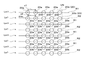
図3は、凹部20を配列してなる第1基本列Lm1及び第1補助列Ls1を説明するための模式図であるため、直線の配列線R1,R2に沿って第1及び第2凹部20a,20bが配列されている様子を示すが、第1基本列Lm1及び第1補助列Ls1は、巨視的には円弧状に延びる配列線R1,R2に沿って多数の第1及び第2凹部20a,20bを有する。また、図3では、説明の便宜上、第1及び第2凹部20a,20bは半球形状であって互いに間隔を空けて図示されているが、実際には半球形状の外周部が互いに重なりを有するように配置され当該重なり合う部分が除去され凹部同士が隣接するように配置されている。
図3に示すように、第1基本列Lm1において隣接する2つの第1凹部20aの中心距離x1は略等しくなっている。また、第1補助列Ls1において隣接する2つの第2凹部20bの中心距離x2は略等しくなっている。実際の第1及び第2凹部20a,20bは、図2(A)等に示すように、それぞれ配列線R1,R2に沿って隙間なく配列されている。
FIG. 3 is a schematic diagram for explaining the first basic row Lm1 and the first auxiliary row Ls1 formed by arranging the
As shown in FIG. 3, the center distances x1 of two adjacent
第1領域AR1は、第1基本列Lm1と第1補助列Ls1とを有し、第1基本列Lm1と第1補助列Ls1とがそれらの列の配列方向に対して交差する方向に交互に繰り返し並列されている。第1基本列Lm1と、表面部3上において第1基本列Lm1に隣接して投射光PLの入射側(すなわちプロジェクター2側であり、概ね−Y軸方向側)に配置される第1補助列Ls1とが対となっている。第1領域AR1において、第1補助列Ls1を構成する第2凹部20bの個数は、図3等に示すように、それと対をなす第1基本列Lm1を構成する第1凹部20aの個数と同一となっている。そして、対をなす第1基本列Lm1と第1補助列Ls1とにおいて、配列線R1,R2に略垂直な方向に隣接する第1凹部20aと第2凹部20bとは、略一対一で配置されるユニットUNを構成している。なお、説明上、このように第1基本列Lm1のうちある1つの第1凹部20aと、第1基本列Lm1に隣接する第1補助列Ls1のうち第1凹部20aに隣接して投射光PLの入射側に配置される1つの第2凹部20bとを、光学的な機能面で一組の単位としてユニットUNとして扱う。1つのユニットUNにおいて、第2凹部20bは、対応する第1凹部20aに投射光PLが入射する光路を確保する役割を有する(図4参照)。
The first area AR1 has a first basic column Lm1 and a first auxiliary column Ls1, and alternately in a direction in which the first basic column Lm1 and the first auxiliary column Ls1 intersect the arrangement direction of those columns. It is repeatedly arranged in parallel. The first basic column Lm1 and the first auxiliary column arranged on the incident side of the projection light PL on the
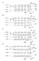
次に、図5(A)及び図5(B)を参照して、上記ユニットUNに対応して一対をなす列Lm1,Ls1間の間隔、及び1つの第1補助列Ls1を挟んで配列される第1基本列Lm1,Lm1間の間隔すなわち第1基本列Lm1のピッチについて説明する。一対をなす列Lm1,Ls1間の間隔及び第1基本列Lm1のピッチは、厳密には、スクリーン基板4に対して投射光PLの入射角θ1が大きくなるほど広くなっている。
Next, with reference to FIG. 5A and FIG. 5B, an interval between a pair of rows Lm1 and Ls1 corresponding to the unit UN and one first auxiliary row Ls1 are arranged. The interval between the first basic rows Lm1 and Lm1, that is, the pitch of the first basic row Lm1 will be described. Strictly speaking, the interval between the pair of rows Lm1 and Ls1 and the pitch of the first basic row Lm1 become wider as the incident angle θ1 of the projection light PL with respect to the
図5(A)は、第1領域AR1内において投射光PLの入射角θ1が比較的小さい部分における第1基本列Lm1と第1補助列Ls1を示している。図5(B)は、第1領域AR1内において投射光PLの入射角θ1が比較的大きい部分における第1基本列Lm1と第1補助列Ls1を示している。一対をなす第1基本列Lm1と第1補助列Ls1との間隔は、投射光PLの入射角θ1が比較的小さい部分の間隔h1よりも、投射光PLの入射角θ1が比較的大きい部分の間隔h2の方が広い。また、第1基本列Lm1のピッチについても、投射光PLの入射角θ1が小さい部分の間隔(ピッチ)c1よりも、投射光PLの入射角θ1が大きい部分の間隔(ピッチ)c2の方が広い。 FIG. 5A shows the first basic row Lm1 and the first auxiliary row Ls1 in a portion where the incident angle θ1 of the projection light PL is relatively small in the first region AR1. FIG. 5B shows the first basic row Lm1 and the first auxiliary row Ls1 in a portion where the incident angle θ1 of the projection light PL is relatively large in the first region AR1. The distance between the pair of first basic row Lm1 and first auxiliary row Ls1 is a portion where the incident angle θ1 of the projection light PL is relatively larger than the interval h1 of the portion where the incident angle θ1 of the projection light PL is relatively small. The interval h2 is wider. As for the pitch of the first basic row Lm1, the interval (pitch) c2 of the portion where the incident angle θ1 of the projection light PL is larger than the interval (pitch) c1 of the portion where the incident angle θ1 of the projection light PL is small. wide.
第1領域AR1において、第3領域AR3との境界側(より入射角θ1が小さい側)では、間隔h1はゼロとなっており、第3領域AR3から離れるにしたがって(入射角θ1が大きくなるにしたがって)、一対をなす列Lm1,Ls1間の間隔と、第1基本列Lm1のピッチとが除々に広くなる。このような構成により、第1領域AR1と第3領域AR3との領域切り替えムラを防止している。 In the first area AR1, on the boundary side with the third area AR3 (the side where the incident angle θ1 is smaller), the interval h1 is zero, and as the distance from the third area AR3 increases (the incident angle θ1 increases). Therefore, the distance between the pair of rows Lm1 and Ls1 and the pitch of the first basic row Lm1 are gradually increased. With such a configuration, region switching unevenness between the first region AR1 and the third region AR3 is prevented.
なお、第1基本列Lm1や第1補助列Ls1を配列すべき円弧状の曲線(配列線R1,R3,R5)には、「円」に限らず、「楕円」や「自由曲線」によるもの、又はこれらの組み合わせも含まれるものとする。さらに、「楕円」や「自由曲線」を構成する曲線と、直線との組み合わせ等も含まれるものとする。 The arcuate curves (arrangement lines R1, R3, R5) in which the first basic row Lm1 and the first auxiliary row Ls1 are to be arranged are not limited to “circles” but are “elliptical” or “free curves”. Or combinations thereof. Furthermore, a combination of a curve forming a “ellipse” or “free curve” and a straight line is also included.
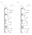
次に、図4を参照して、第1凹部20a上に形成される反射膜RSについて説明する。第1凹部20aは、その表面のうち少なくとも一部分では投射光PLを正面側に反射し、その他の部分では外光を吸収又は透過する。具体的には、図4に示すように、それぞれの第1凹部20aは、その表面Su1の一部にプロジェクター2からの投射光PLが入射する位置に対応して投射光PLを反射させる反射膜RSが形成されている。一方、第1凹部20aのうち反射膜RSが形成されていない部分は、表面部3の基材やスクリーン基板4の性質により、入射光の吸収を可能にする。すなわち、第1凹部20aは、スクリーン1の下方からの投射光PLを反射光RLとして観察者(スクリーン1の正面)側に反射し、上方からの外光OLを観察者側に反射しないようになっている。
Next, the reflective film RS formed on the
図4に示すように、第2凹部20bの表面Su2には、反射膜RSが形成されていない。つまり、第2凹部20bは、表面部3の基材やスクリーン基板4の性質により、入射光の吸収を可能にする。
As shown in FIG. 4, the reflective film RS is not formed on the surface Su2 of the
次に第2領域AR2について説明する。図1(B)に示すように、第2領域AR2は、第1領域AR1よりも投射光PLのスクリーン1に対する入射角が大きくなる位置に設けられている。
Next, the second area AR2 will be described. As shown in FIG. 1B, the second area AR2 is provided at a position where the incident angle of the projection light PL with respect to the
図6(A)、6(B)は、表面部3のうち第2領域AR2の一部を拡大した図である。図7は、図6(A)、6(B)の凹部20の配列パターンを説明する模式図である。図8は、図6(A)に示す投射光線方向のB−B断面の図である。なお、図6(A)、6(B)において、プロジェクター2の投射光PLがB−B方向に沿って入射する。
6A and 6B are enlarged views of a part of the second area AR2 in the
図7は、凹部20を配列してなる第2基本列Lm2及び第2補助列Ls2を説明するための模式図であり拡大図であるため、直線の配列線R3,R4に沿って第3及び第4凹部20c,20dが配列されている様子を示すが、第2基本列Lm2及び第2補助列Ls2は、巨視的には円弧状に延びる配列線R3,R4に沿って多数の第3及び第4凹部20c,20dを有する。また、図7では、説明の便宜上、第3及び第4凹部20c,20dは半球形状であって互いに間隔を空けて図示されているが、実際には半球形状の外周部が互いに重なりを有するように配置され当該重なり合う部分が除去され凹部同士が隣接するように配置されている。
図7に示すように、第2基本列Lm2において隣接する2つの第3凹部20cの中心距離x3は略等しくなっている。また、第2補助列Ls2において隣接する2つの第4凹部20dの中心距離x4は略等しくなっている。実際の第3及び第4凹部20c,20dは、図6(A)等に示すように、それぞれ配列線R3,R4に沿って隙間なく配列されている。
FIG. 7 is a schematic diagram for explaining the second basic row Lm2 and the second auxiliary row Ls2 in which the
As shown in FIG. 7, the center distances x3 of two adjacent
第2領域AR2は、第2基本列Lm2と第2補助列Ls2とを有し、第2基本列Lm2と第2補助列Ls2とがそれらの列の配列方向に対して交差する方向に交互に繰り返し並列されている。第2基本列Lm2と、表面部3上において第2基本列Lm2に隣接して投射光PLの入射側(すなわちプロジェクター2側であり、概ね−Y軸方向側)に配置される第2補助列Ls2とが対となっている。第2領域AR2において、第2補助列Ls2を構成する第4凹部20dの個数は、図7に示すように、それと対をなす第2基本列Lm2を構成する第3凹部20cの個数よりも数が多くなっている。そして、本実施形態の場合、対をなす第2基本列Lm2と第2補助列Ls2とにおいて、配列線R3,R4に略垂直な方向に隣接する第3凹部20cと第4凹部20dとは、略一対二で配置されるユニットUNを構成している。なお、説明上、このように第2基本列Lm2のうちある1つの第3凹部20cと、第2基本列Lm2に隣接する第2補助列Ls2のうち第3凹部20cに隣接して投射光PLの入射側に配置される2つの第4凹部20dとを一組の単位としてユニットUNとして扱う(図6(A)等参照)。1つのユニットUNにおいて、2つの第4凹部20dは、対応する1つの第3凹部20cに投射光PLが入射する光路を確保する役割を有する(図8参照)。
The second area AR2 has a second basic column Lm2 and a second auxiliary column Ls2, and alternately in a direction in which the second basic column Lm2 and the second auxiliary column Ls2 intersect the arrangement direction of those columns. It is repeatedly arranged in parallel. The second basic column Lm2 and the second auxiliary column arranged on the incident side of the projection light PL on the
次に、図5(C)及び図5(D)を参照して、一対をなす列Lm2,Ls2間の間隔及び1つの第2補助列Ls2を挟んで配列される第2基本列Lm2,Lm2間の間隔、すなわち第2基本列Lm2のピッチについて説明する。一対をなす列Lm2,Ls2間の間隔及び第2基本列Lm2のピッチは、厳密には、スクリーン基板4に対して投射光PLの入射角θ2が大きくなるほど広くなっている。
Next, referring to FIG. 5C and FIG. 5D, the distance between the pair of rows Lm2 and Ls2 and the second basic rows Lm2 and Lm2 arranged with one second auxiliary row Ls2 interposed therebetween. The interval between them, that is, the pitch of the second basic row Lm2 will be described. Strictly speaking, the distance between the pair of rows Lm2 and Ls2 and the pitch of the second basic row Lm2 become wider as the incident angle θ2 of the projection light PL with respect to the
図5(C)は、第2領域AR2内において投射光PLの入射角θ2が比較的小さい部分における第2基本列Lm2と第2補助列Ls2を示している。図5(D)は、第2領域AR2において投射光PLの入射角θ2が比較的大きい部分における第2基本列Lm2と第2補助列Ls2を示している。一対をなす第2基本列Lm2と第2補助列Ls2との間隔は、投射光PLの入射角θ2が比較的小さい部分の間隔h3よりも、投射光PLの入射角θ2が比較的大きい部分の間隔h4の方が広い。また、第2基本列Lm2のピッチについても、投射光PLの入射角θ2が比較的小さい部分の間隔(ピッチ)c3よりも、投射光PLの入射角θ2が比較的大きい部分の間隔(ピッチ)c4の方が広い。 FIG. 5C shows the second basic row Lm2 and the second auxiliary row Ls2 in the portion where the incident angle θ2 of the projection light PL is relatively small in the second region AR2. FIG. 5D shows the second basic row Lm2 and the second auxiliary row Ls2 in the portion where the incident angle θ2 of the projection light PL is relatively large in the second region AR2. The distance between the pair of second basic row Lm2 and second auxiliary row Ls2 is a portion where the incident angle θ2 of the projection light PL is relatively larger than the interval h3 of the portion where the incident angle θ2 of the projection light PL is relatively small. The interval h4 is wider. Further, with respect to the pitch of the second basic row Lm2, the interval (pitch) between the portions where the incident angle θ2 of the projection light PL is relatively larger than the interval (pitch) c3 where the incident angle θ2 of the projection light PL is relatively small. c4 is wider.
次に、図8を参照して、第3凹部20c上に形成される反射膜RSについて説明する。第3凹部20cは、その表面のうち少なくとも一部分では投射光PLを正面側に反射し、その他の部分では外光を吸収又は透過する。具体的には、図8に示すように、それぞれの第3凹部20cは、その表面Su3にプロジェクター2からの投射光PLが入射する位置に対応して投射光PLを反射させる反射膜RSが形成されている。一方、第3凹部20cのうち反射膜RSが形成されていない部分は、表面部3の基材やスクリーン基板4の性質により、入射光の吸収を可能にする。すなわち、第3凹部20cは、スクリーン1の下方からの投射光PLを反射光RLとして観察者側に反射し、上方からの外光OLを観察者側に反射しないようになっている。
Next, the reflective film RS formed on the
図8に示すように、それぞれの第4凹部20dの表面Su4には、反射膜RSが形成されていない。つまり、第4凹部20dは、表面部3の基材やスクリーン基板4の性質により、入射光の吸収を可能にする。
As shown in FIG. 8, the reflective film RS is not formed on the surface Su4 of each
図9は、第2領域AR2内において第1領域AR1との境界付近に設けられる遷移領域ARxの凹部20の配列パターンを説明する模式図である。遷移領域ARxにおいて、1つのユニットUNを構成する第3凹部20cの個数と第4凹部20dの個数とは略一対二になっているものの、1つの第3凹部20cに対応する2つの第4凹部20d間の中心距離が異なる。具体的には、図9に示すように、相対的に上方向(+Y軸方向)の部分、つまりスクリーン基板4に対して投射光PLの入射角θ2が大きくなる部分ほど、1つのユニットUN内で隣接する第4凹部20dの中心距離が大きくなっている。すなわち、図9に示す隣接する第4凹部20dの中心距離x5,x6,x7,x8は、x5<x6<x7<x8の関係を満たす。例えば、第1領域AR1に最も近い第2補助列Ls2において、同一ユニットUN内で隣接する第4凹部20dの中心距離x5は、略ゼロであり、2つの第4凹部20dは見かけ上略重なり合った状態となっている。一方、第1領域AR1から最も遠い第2補助列Ls2において、同一ユニットUN内で隣接する第4凹部20dの中心距離x8は、隣り合うユニットUN同士の第3凹部20c間の中心距離x3の略半分となっている。
FIG. 9 is a schematic diagram for explaining the arrangement pattern of the
図10は、第3領域AR3の凹部20の配列パターンを説明する模式図である。図11は、第3領域AR3の投射光線方向の断面図である。第3領域AR3は、第3基本列Lm3を有する。第3基本列Lm3は、巨視的に円弧状に延びる配列線R5に沿って多数の第5凹部20eを有する。隣接する2つの第5凹部20eの中心距離x9は略等しくなっている。実際の第5凹部20eは、配列線R5に沿って半球形状の外周部が互いに重なりを有するように配置され当該重なり合う部分が除去され凹部同士が隣接するように隙間なく配列されている。図11に示すように、それぞれの第5凹部20eは、その表面Su5にプロジェクター2からの投射光PLが入射する位置に対応して投射光PLを反射させる反射膜RSが形成されている。一方、第5凹部20eのうち反射膜RSが形成されていない部分は、表面部3の基材やスクリーン基板4の性質により、入射光の吸収を可能にする。すなわち、第5凹部20eは、スクリーン1の下方からの投射光PLを反射光RLとして観察者側に反射し、上方からの外光OLを観察者側に反射しないようになっている。
FIG. 10 is a schematic diagram for explaining the arrangement pattern of the
以上において、第1領域AR1中の第1基本列Lm1、第2領域AR2中の第2基本列Lm2は、図5に示されるように、間隔h1<h2<h3<h4の関係になるように配列されている。従って、第1領域AR1中の第1基本列Lm1の密度よりも、第2領域AR2中の第2基本列Lm2の密度の方が少なくなる。
また、第1領域AR1中の第1基本列Lm1、第2領域AR2中の第2基本列Lm2、及び第3領域AR3中の第3基本列Lm3において、凹部20a,20c,20eの間隔x1,x3,x9は、図3,図7,図10では、略等しく示されている。しかしながら、凹部20a,20c,20eの間隔x1,x3,x9は、実際にはスクリーン1全体の表示態様が適切となるように、それぞれ調整されている。
In the above, the first basic column Lm1 in the first area AR1 and the second basic column Lm2 in the second area AR2 have a relationship of an interval h1 <h2 <h3 <h4 as shown in FIG. It is arranged. Accordingly, the density of the second basic column Lm2 in the second area AR2 is smaller than the density of the first basic column Lm1 in the first area AR1.
Further, in the first basic row Lm1 in the first area AR1, the second basic row Lm2 in the second area AR2, and the third basic row Lm3 in the third area AR3, the intervals x1, the
以下、スクリーン1の製造方法について説明する。まず、スクリーン1のうち、スクリーン基板4及び表面部3を形成するための下地シートの作製について説明する。下地シートは、例えば光吸収性を有する黒色のポリ塩化ビニルを原材料とする部材を主たる原材料として形成される。具体的には、例えばポリ塩化ビニル製のシートの表面を加熱して軟化させた後、多数の凹部20に対応する凹凸形状を有する型を用いて凹凸形状をプレス加工する。これにより、スクリーン1の下地シートに凹部20(20a,20b,20c,20d,20e)に相当する多数の微細な凹凸形状が形成される。なお、ポリ塩化ビニル製のシートは、グラスファイバ等によって強度を高めたものとすることもできる。
Hereinafter, a method for manufacturing the
次に、スクリーン1の下地シート上の第1、第3、及び第5凹部20a,20c,20eにそれぞれ形成される反射膜RSの製造工程について説明する。反射膜RSの成膜には、例えば真空蒸着による成膜を行う成膜装置を用いる。なお、成膜材料として例えばアルミニウムを用いている。スクリーン1の下地シートは、成膜装置を構成する円筒状の真空容器の内壁面に沿って所定の高さ位置で固定されている。成膜装置は、真空容器中で成膜材料を加熱し蒸発させ、第1、第3、及び第5凹部20a,20c,20e上に反射膜RSを堆積させる。なお、成膜装置は、真空容器中において、スクリーン1への投射光PLの入射方向と同じ方向に蒸着源を配置するものとなる。これにより、反射膜RSを投射光PLに対応するものとして下地シートに対して傾いた方向から斜めに蒸着することができ、反射膜RSを第1、第3、及び第5凹部20a,20c,20e上の適所に形成することができる。
Next, a manufacturing process of the reflective film RS formed in each of the first, third, and
なお、スクリーン基板4及び表面部3を形成するための下地シートは、例えば光透過性を有する透明PET(ポリエチレンテレフタレート)等を原材料とするシート状の部材を基材として背面に光吸収性の黒インクを塗布したものを用いてもよい。
The base sheet for forming the
以上において、凹部20は、重なりを有するように配置されるため、隣接する凹部20間に突起が形成される。具体的には、第1領域AR1においては、図2(B)及び図4に示すように、隣接するユニットUNの第1凹部20aと第2凹部20bとの間のコーナー部に突起31が形成される。また、第2領域AR2においては、図6(B)及び図8に示すように、隣接するユニットUNの第3凹部20cと第4凹部20dとの間のコーナー部及び中間に突起32が形成される。上述したように、第1領域AR1の1つのユニットUNにおける第1補助列Ls1の第2凹部20bの個数よりも、第2領域AR2の1つのユニットUNにおける第2補助列Ls2の第4凹部20dの個数が多い。そのため、第1基本列Lm1の配列線R1のピッチと第2基本列Lm2の配列線R3のピッチが等しい場合において、第1領域AR1におけるY軸方向に隣接するユニットUN間に形成される突起31の高さよりも、第2領域AR2におけるY軸方向に隣接するユニットUN間に形成される突起32の高さの方が比較的低くなる。
In the above, since the
以下、凹部20と投射光PLとの関係について説明する。図12(A)は、図2(A)の第1領域AR1の凹部20のA−A断面図と投射光PL1,PL2との関係を説明する図である。図12(B)は、図6(A)の第2領域AR2の凹部20のB−B断面図と投射光PL2との関係を説明する図である。なお、実際には、凹部20の配列の仕方により同一領域内でも凹部境界部の突起の高さは一様ではないが、第1領域AR1及び第2領域AR2それぞれにおいて投射光PLに特に関係する突起31,32について説明する。図1に示すスクリーン1上の第1領域AR1の位置においては、図12(A)に示すように、第1凹部20aの投射光PL1が入射してくる側にある高い突起31に投射光PL1が遮られることなく、投射光PL1が第1凹部20aの反射膜RSに入射する。しかしながら、図1に示すスクリーン1上の第2領域AR2の位置に第1領域AR1と同様の微細凹凸構造を設けた場合、図12(A)に示すように、高い突起31によって投射光PL2が遮られ、投射光PL2が第1凹部20aの反射膜RSに入射しない。一方、図1に示すスクリーン1上の第2領域AR2においては、図12(B)に示すように、第3凹部20cの投射光PL2が入射してくる側にある低い突起32に投射光PL2が遮られることなく、投射光PL2が第3凹部20cの反射膜RSに入射する。
Hereinafter, the relationship between the
以上説明したように、本実施形態に係るスクリーン1は、第1及び第2基本列Lm1,Lm2に加え、第1及び第2補助列Ls1,Ls2を設けることにより、投射光PLのスクリーン1への入射角が大きい場合でも、第1及び第3凹部20a,20cに形成された反射膜RSに投射光PLを十分に入射させることができる。また、第2領域AR2において、第2基本列Lm2の第3凹部20cよりも第2補助列Ls2の第4凹部20dの個数を多くすることにより、第1領域AR1の突起31の高さよりも第2領域AR2の突起32の高さを低くすることができる。これにより、第2領域AR2において第1領域AR1よりも投射光PLのスクリーン1への入射角が大きくなっても、投射光PLが突起32で遮られることを抑制でき、視野欠損を低減することができる。
As described above, the
また、本実施形態では、遷移領域ARxにおいて、第1領域AR1から離れるほど1つユニットUN内の第3凹部20cに隣接する2つの第4凹部20d間の距離を除々に大きくしていくことにより、第1領域AR1の凹部20の配列からそれとは異なる第2領域AR2の凹部20の配列へと少しずつ変えていくことができる。そのため、第1領域AR1から第2領域AR2への切り替えによって、第1領域AR1と第2領域AR2との境界部で反射された画像表示に切り替えムラが生じるのを防ぐことができる。
In the present embodiment, in the transition area ARx, the distance between the two
〔第2実施形態〕
図13は、第2実施形態に係るスクリーン1について説明する図である。本実施形態に係るスクリーン1は、遷移領域ARxの配列パターンを除いて第1実施形態に係るスクリーン1と同様であるので、重複する部分の説明は省略する。
[Second Embodiment]
FIG. 13 is a diagram illustrating the
遷移領域ARxにおいて、1つのユニットUN内の第3凹部20cに対応する第4凹部20dの個数は一定しておらず、図13に示すように、スクリーン基板4に対して投射光PLの入射角が大きくなるほど、隣接する第4凹部20dの個数が除々に多くなっている。すなわち、第1領域AR1に最も近い第2補助列Ls2(図13の最下列)において、隣接する第4凹部20dの個数の増加はゼロであり、見かけ上第3凹部20cと第4凹部20dの個数は一対一となっている。第2補助列Ls2が第1領域AR1から遠ざかるにつれ、第2補助列Ls2を構成する第4凹部20dの個数は除々に増加し、第1領域AR1から最も遠い第2補助列Ls2(図13の最上列)において、隣接する第4凹部20dの個数は、第2基本列Lm2を構成する第3凹部20cの個数の2倍となる。ここで、第4凹部20dを増加させる配列方向の位置はランダムに設定するものとする。
In the transition area ARx, the number of the
以上説明したように、本実施形態に係るスクリーン1は、遷移領域ARxにおいて、第2補助列Ls2の第4凹部20dの個数を第1領域AR1から離れるにしたがって除々に増やしていくことにより、第1領域AR1から第2領域AR2への切り替えよって、第1領域AR1と第2領域AR2との境界に切り替えムラが生じるのを防ぐことができる。
As described above, the
以上、各実施形態について説明してきたが、本発明は上記実施形態に限定されるものではない。例えば、上記実施形態では、第1領域AR1、第2領域AR2、及び第3領域AR3のそれぞれの配置や範囲は、図1に示したものに限らず、プロジェクター2からの投射光PLを効率的に反射させる配置や範囲であればよい。例えば、投射光PLと各列Lm1,Lm2,Ls1,Ls2とが必ずしも直交しなくてもよい。
As mentioned above, although each embodiment has been described, the present invention is not limited to the above embodiment. For example, in the above embodiment, the arrangement and range of the first area AR1, the second area AR2, and the third area AR3 are not limited to those shown in FIG. 1, but the projection light PL from the
また、上記実施形態では、第2領域AR2において、1つの第3凹部20cに対応する第4凹部20dの個数を2つとしたが、3つ以上であってもよい。さらに、2.5、3.5等の非整数であってもよい。なお、1つの第3凹部20cに対応する第4凹部20dの個数が4つ以上になると、第2補助列Ls2を設ける効果が上記の場合と変わらないうえ、遷移領域ARxにおいて第4凹部20dの配置等の調整が難しくなる。
Moreover, in the said embodiment, although the number of the 4th recessed
また、上記実施形態では、反射膜RSの形成において、成膜材料としてアルミニウムを用いているが、アルミニウムの他にも、例えば銀や誘電体多層膜等を用いることも可能である。また、反射膜RSを金属膜で形成する場合、金属膜の上にさらに保護膜を形成させることも可能である。 In the above embodiment, aluminum is used as a film forming material in the formation of the reflective film RS. However, other than aluminum, for example, silver or a dielectric multilayer film can also be used. In addition, when the reflective film RS is formed of a metal film, a protective film can be further formed on the metal film.
また、上記実施形態において、第1、第3、及び第5凹部20a,20c,20eに反射膜RSを形成する前に、表面部3の表面活性化処理を行うこともできる。表面部3の表面活性化処理としては、逆スタッパー処理、プラズマ放電処理、コロナ放電処理、RFボンバード処理、大気圧プラズマ処理等を採用することができる。表面部3に対して表面活性化処理を適宜施すことにより、反射膜RSの付着力や耐久性を向上させることができる。
Moreover, in the said embodiment, before forming reflective film RS in the 1st, 3rd and 5th recessed
また、上記実施形態において、スクリーン1全体を考慮して、第1及び第2領域AR1,AR2がプロジェクター2からの投射光PLを効率的に反射させる配置や範囲にあれば、必ずしも第3領域AR3を設けなくてもよい。
In the above embodiment, if the first and second areas AR1 and AR2 are in an arrangement or range that efficiently reflects the projection light PL from the
1…スクリーン、 2…プロジェクター、 3…表面部、 4…スクリーン基板、 20,20a,20b,20c,20d,20e…凹部、 AR1,AR2,AR3,ARx…領域、 Lm1,Lm2,Lm3…基本列、 Ls1,Ls2…補助列、 RS…反射面、 PL,PL1,PL2…投射光、 RL…反射光、OL…外光
DESCRIPTION OF
Claims (7)
前記スクリーン基板上に形成され、光を反射する複数の第1凹部を有する第1基本列と、前記スクリーン基板上で前記第1基本列に隣接して形成され、前記隣接する第1凹部と同一の個数の第2凹部を有する第1補助列とを有し、前記第1基本列と前記第1補助列とが交互に繰り返し配列される第1領域と、
前記スクリーン基板上で前記第1領域よりも投射光の前記スクリーン基板への入射角が大きい位置に形成され、光を反射する複数の第3凹部を有する第2基本列と、前記スクリーン基板上で前記第2基本列に隣接して形成され、前記隣接する第3凹部より多い個数の第4凹部を有する第2補助列とを有し、前記第2基本列と前記第2補助列とが交互に繰り返し配列される第2領域と、
を備えるスクリーン。 A screen substrate on which projection light is projected from the front lower side,
A first basic row formed on the screen substrate and having a plurality of first recesses for reflecting light, and formed adjacent to the first basic row on the screen substrate and identical to the adjacent first recesses A first region having a number of second recesses, and the first basic row and the first auxiliary row are alternately and repeatedly arranged,
A second basic row formed on the screen substrate at a position where an incident angle of the projection light to the screen substrate is larger than that of the first region and having a plurality of third recesses for reflecting the light; A second auxiliary row formed adjacent to the second basic row and having a larger number of fourth concave portions than the adjacent third concave portions, and the second basic row and the second auxiliary row are alternately arranged. A second region repeatedly arranged in
With screen.
前記第1凹部及び前記第3凹部の表面の前記少なくとも一部以外と、前記第2凹部及び前記第4凹部の表面は、投射光を吸収し又は透過させる、請求項1に記載のスクリーン。 A reflective part is formed on at least a part of the surfaces of the first concave part and the third concave part, and the reflected light is reflected to the front side by the reflective part
2. The screen according to claim 1, wherein the surfaces of the first recess and the third recess except for at least a part of the surface and the surfaces of the second recess and the fourth recess absorb or transmit the projection light.
Priority Applications (3)
| Application Number | Priority Date | Filing Date | Title |
|---|---|---|---|
| JP2009218619A JP5482049B2 (en) | 2009-09-24 | 2009-09-24 | screen |
| US12/876,627 US7911694B1 (en) | 2009-09-24 | 2010-09-07 | Screen |
| CN2010102906332A CN102033408B (en) | 2009-09-24 | 2010-09-21 | Screen |
Applications Claiming Priority (1)
| Application Number | Priority Date | Filing Date | Title |
|---|---|---|---|
| JP2009218619A JP5482049B2 (en) | 2009-09-24 | 2009-09-24 | screen |
Publications (3)
| Publication Number | Publication Date |
|---|---|
| JP2011069859A JP2011069859A (en) | 2011-04-07 |
| JP2011069859A5 JP2011069859A5 (en) | 2012-08-09 |
| JP5482049B2 true JP5482049B2 (en) | 2014-04-23 |
Family
ID=43741784
Family Applications (1)
| Application Number | Title | Priority Date | Filing Date |
|---|---|---|---|
| JP2009218619A Expired - Fee Related JP5482049B2 (en) | 2009-09-24 | 2009-09-24 | screen |
Country Status (3)
| Country | Link |
|---|---|
| US (1) | US7911694B1 (en) |
| JP (1) | JP5482049B2 (en) |
| CN (1) | CN102033408B (en) |
Families Citing this family (8)
| Publication number | Priority date | Publication date | Assignee | Title |
|---|---|---|---|---|
| WO2009089256A1 (en) * | 2008-01-07 | 2009-07-16 | The Salk Institute For Biological Studies | Projection screens for three dimensional images |
| JP2010066750A (en) * | 2008-08-12 | 2010-03-25 | Seiko Epson Corp | Method of manufacturing screen and screen |
| JP5239832B2 (en) * | 2008-12-24 | 2013-07-17 | セイコーエプソン株式会社 | screen |
| JP5521655B2 (en) * | 2009-04-10 | 2014-06-18 | セイコーエプソン株式会社 | Reflective screen, projection system, front projection television, and reflective screen manufacturing method |
| JP2011164391A (en) * | 2010-02-10 | 2011-08-25 | Seiko Epson Corp | Reflective screen |
| JP2012198396A (en) * | 2011-03-22 | 2012-10-18 | Seiko Epson Corp | Screen manufacturing method and partial screen |
| JP2013011714A (en) * | 2011-06-29 | 2013-01-17 | Seiko Epson Corp | Screen manufacturing method and screen |
| US8964292B1 (en) | 2012-06-25 | 2015-02-24 | Rawles Llc | Passive anisotropic projection screen |
Family Cites Families (9)
| Publication number | Priority date | Publication date | Assignee | Title |
|---|---|---|---|---|
| JPH0545733A (en) * | 1991-08-13 | 1993-02-26 | Pioneer Electron Corp | Front screen |
| JPH11142975A (en) * | 1997-11-13 | 1999-05-28 | Matsushita Electric Ind Co Ltd | Reflection type and its manufacture |
| JP2002090512A (en) * | 2000-06-16 | 2002-03-27 | Matsushita Electric Ind Co Ltd | Reflector and reflection type liquid crystal display device having the reflector |
| JP2004037794A (en) * | 2002-07-03 | 2004-02-05 | Sony Corp | Screen for projection |
| JP2005062312A (en) * | 2003-08-08 | 2005-03-10 | Olympus Corp | Projection screen and projection type display device |
| JP2009015195A (en) * | 2007-07-09 | 2009-01-22 | Seiko Epson Corp | Reflection screen |
| JP4479832B2 (en) * | 2007-07-20 | 2010-06-09 | セイコーエプソン株式会社 | screen |
| JP2009145447A (en) * | 2007-12-12 | 2009-07-02 | Seiko Epson Corp | Screen and projection system |
| JP5521655B2 (en) * | 2009-04-10 | 2014-06-18 | セイコーエプソン株式会社 | Reflective screen, projection system, front projection television, and reflective screen manufacturing method |
-
2009
- 2009-09-24 JP JP2009218619A patent/JP5482049B2/en not_active Expired - Fee Related
-
2010
- 2010-09-07 US US12/876,627 patent/US7911694B1/en not_active Expired - Fee Related
- 2010-09-21 CN CN2010102906332A patent/CN102033408B/en not_active Expired - Fee Related
Also Published As
| Publication number | Publication date |
|---|---|
| US7911694B1 (en) | 2011-03-22 |
| CN102033408B (en) | 2012-07-18 |
| CN102033408A (en) | 2011-04-27 |
| JP2011069859A (en) | 2011-04-07 |
| US20110069385A1 (en) | 2011-03-24 |
Similar Documents
| Publication | Publication Date | Title |
|---|---|---|
| JP5482049B2 (en) | screen | |
| JP5239832B2 (en) | screen | |
| JP4479832B2 (en) | screen | |
| JP5598239B2 (en) | Light irradiation device | |
| US9274370B2 (en) | Light-emitting device, backlight device, and image display apparatus | |
| JP6812761B2 (en) | Reflective screen, video display device | |
| CN113436560B (en) | Imaging optical system and display device | |
| JP5251994B2 (en) | Light irradiation apparatus and light irradiation method | |
| JP6361828B2 (en) | Aerial video display | |
| US8405905B2 (en) | Screen | |
| JP4487567B2 (en) | Rear projection screen | |
| US9513486B2 (en) | Optical imaging apparatus | |
| JP2018077322A (en) | Reflection screen and image display device | |
| JP2017134315A (en) | Screen and image display device | |
| JP2012093692A (en) | Light radiation device and light radiation method | |
| JP5447701B2 (en) | screen | |
| JP2016200784A (en) | Screen and display device | |
| JP2018040893A (en) | Image display device | |
| JP2009145447A (en) | Screen and projection system | |
| JP2013023088A (en) | Rearview mirror with monitor | |
| JP2010044137A (en) | Screen | |
| JP5228171B2 (en) | Optical element | |
| TWI717044B (en) | Photosynthesis demultiplexer | |
| JP2009047882A (en) | Screen | |
| JP2014086372A (en) | Light irradiation device |
Legal Events
| Date | Code | Title | Description |
|---|---|---|---|
| A521 | Request for written amendment filed |
Free format text: JAPANESE INTERMEDIATE CODE: A523 Effective date: 20120625 |
|
| A621 | Written request for application examination |
Free format text: JAPANESE INTERMEDIATE CODE: A621 Effective date: 20120625 |
|
| A977 | Report on retrieval |
Free format text: JAPANESE INTERMEDIATE CODE: A971007 Effective date: 20130326 |
|
| A131 | Notification of reasons for refusal |
Free format text: JAPANESE INTERMEDIATE CODE: A131 Effective date: 20130812 |
|
| A521 | Request for written amendment filed |
Free format text: JAPANESE INTERMEDIATE CODE: A523 Effective date: 20131008 |
|
| A131 | Notification of reasons for refusal |
Free format text: JAPANESE INTERMEDIATE CODE: A131 Effective date: 20131105 |
|
| A521 | Request for written amendment filed |
Free format text: JAPANESE INTERMEDIATE CODE: A523 Effective date: 20131217 |
|
| TRDD | Decision of grant or rejection written | ||
| A01 | Written decision to grant a patent or to grant a registration (utility model) |
Free format text: JAPANESE INTERMEDIATE CODE: A01 Effective date: 20140121 |
|
| A61 | First payment of annual fees (during grant procedure) |
Free format text: JAPANESE INTERMEDIATE CODE: A61 Effective date: 20140203 |
|
| R150 | Certificate of patent or registration of utility model |
Ref document number: 5482049 Country of ref document: JP Free format text: JAPANESE INTERMEDIATE CODE: R150 |
|
| S531 | Written request for registration of change of domicile |
Free format text: JAPANESE INTERMEDIATE CODE: R313531 |
|
| R350 | Written notification of registration of transfer |
Free format text: JAPANESE INTERMEDIATE CODE: R350 |
|
| LAPS | Cancellation because of no payment of annual fees |