JP5481005B2 - Member for preventing bumping of bumper beam for vehicle - Google Patents
Member for preventing bumping of bumper beam for vehicle Download PDFInfo
- Publication number
- JP5481005B2 JP5481005B2 JP2010009506A JP2010009506A JP5481005B2 JP 5481005 B2 JP5481005 B2 JP 5481005B2 JP 2010009506 A JP2010009506 A JP 2010009506A JP 2010009506 A JP2010009506 A JP 2010009506A JP 5481005 B2 JP5481005 B2 JP 5481005B2
- Authority
- JP
- Japan
- Prior art keywords
- vehicle
- bumper beam
- plate portion
- wall
- width direction
- Prior art date
- Legal status (The legal status is an assumption and is not a legal conclusion. Google has not performed a legal analysis and makes no representation as to the accuracy of the status listed.)
- Expired - Fee Related
Links
Images


Classifications
-
- B—PERFORMING OPERATIONS; TRANSPORTING
- B60—VEHICLES IN GENERAL
- B60R—VEHICLES, VEHICLE FITTINGS, OR VEHICLE PARTS, NOT OTHERWISE PROVIDED FOR
- B60R19/00—Wheel guards; Radiator guards, e.g. grilles; Obstruction removers; Fittings damping bouncing force in collisions
- B60R19/02—Bumpers, i.e. impact receiving or absorbing members for protecting vehicles or fending off blows from other vehicles or objects
- B60R19/18—Bumpers, i.e. impact receiving or absorbing members for protecting vehicles or fending off blows from other vehicles or objects characterised by the cross-section; Means within the bumper to absorb impact
-
- B—PERFORMING OPERATIONS; TRANSPORTING
- B60—VEHICLES IN GENERAL
- B60R—VEHICLES, VEHICLE FITTINGS, OR VEHICLE PARTS, NOT OTHERWISE PROVIDED FOR
- B60R19/00—Wheel guards; Radiator guards, e.g. grilles; Obstruction removers; Fittings damping bouncing force in collisions
- B60R19/02—Bumpers, i.e. impact receiving or absorbing members for protecting vehicles or fending off blows from other vehicles or objects
- B60R19/023—Details
-
- B—PERFORMING OPERATIONS; TRANSPORTING
- B60—VEHICLES IN GENERAL
- B60R—VEHICLES, VEHICLE FITTINGS, OR VEHICLE PARTS, NOT OTHERWISE PROVIDED FOR
- B60R19/00—Wheel guards; Radiator guards, e.g. grilles; Obstruction removers; Fittings damping bouncing force in collisions
- B60R19/02—Bumpers, i.e. impact receiving or absorbing members for protecting vehicles or fending off blows from other vehicles or objects
- B60R19/18—Bumpers, i.e. impact receiving or absorbing members for protecting vehicles or fending off blows from other vehicles or objects characterised by the cross-section; Means within the bumper to absorb impact
- B60R2019/186—Additional energy absorbing means supported on bumber beams, e.g. cellular structures or material
Description
本発明は車両用バンパービームに係り、特に、衝突物の下にバンパービームがもぐり込んだりバンパービームの下に衝突物がもぐり込んだりしてラジエーター等の車両部品を損傷することを防止するもぐり込み防止部材に関するものである。 The present invention relates to a bumper beam for a vehicle, and more particularly, a roll-in preventing member that prevents a bumper beam from rolling under a collision object or a collision object from under a bumper beam to damage vehicle parts such as a radiator. It is about.
車両の前部または後部に車両幅方向に略水平に配設されるバンパービーム(バンパーリインフォースメントともいう)が広く用いられているが、衝突物の下にバンパービームがもぐり込んだりバンパービームの下に衝突物がもぐり込んだりして、ラジエーター等の車両部品を損傷することがある。これを防止するため、バンパービームの上方または下方へ突き出すもぐり込み防止部材をバンパービームに一体的に固設することが考えられている。特許文献1に記載の装置はその一例で、(a) バンパービームの上部に固定される底壁と、(b) 該底壁に立設されているもぐり込み防止壁と、(c) 該もぐり込み防止壁の一端並びに前記底壁の一端に接続している第1補強側壁と、(d) 該第1補強側壁と平行にそれぞれの他端に接続している第2補強側壁とを有して構成されている。また、特許文献2には、断面がコの字形状乃至はU字形状を成すもぐり込み防止部材が、矩形状のバンパービームの上端部を跨ぐように配設され、コの字形状の開口端縁がバンパービームの外側壁および内側壁にそれぞれ一体的に溶接接合されている。 Bumper beams (also called bumper reinforcements) that are arranged almost horizontally in the vehicle width direction are widely used at the front or rear of the vehicle. However, the bumper beam digs under the collision object or under the bumper beam. Collisions may get caught and damage to vehicle parts such as radiators. In order to prevent this, it is considered to integrally fix the bumper beam to the bumper beam so as to protrude upward or downward of the bumper beam. The device described in Patent Document 1 is an example thereof, (a) a bottom wall fixed to the upper part of the bumper beam, (b) a digging prevention wall standing on the bottom wall, and (c) the grooving. A first reinforcing side wall connected to one end of the wall to prevent entrainment and one end of the bottom wall; and (d) a second reinforcing side wall connected to the other end in parallel with the first reinforcing side wall. Configured. Further, in Patent Document 2, an anti-scribing member having a U-shaped or U-shaped cross section is disposed so as to straddle the upper end portion of the rectangular bumper beam, and the U-shaped opening end. The edges are integrally welded to the outer and inner walls of the bumper beam.
しかしながら、特許文献1記載の装置は構造が複雑で、折曲げ成形したり重ね合わせて接合したりする必要があり、製造コストが高くなる。特許文献2に記載の装置では、衝突によりバンパービームが車両内方側へ変形させられた場合に、もぐり込み防止部材の突出端がバンパービームよりも車両内側へ侵入することがあり(図2(b) 参照)、もぐり込み防止部材の存在により却ってラジエーター等の車両部品と干渉して損傷する可能性が高くなる場合がある。 However, the apparatus described in Patent Document 1 has a complicated structure, and needs to be bent or overlaid and joined, resulting in an increase in manufacturing cost. In the device described in Patent Document 2, when the bumper beam is deformed inward of the vehicle by a collision, the protruding end of the anti-roll-in member may enter the inside of the vehicle from the bumper beam (FIG. 2 ( b))), there is a possibility that the possibility of damage due to interference with vehicle parts such as radiators may increase due to the presence of the anti-roll-in member.
本発明は以上の事情を背景として為されたもので、その目的とするところは、もぐり込みによる車両部品の損傷を適切に抑制できるもぐり込み防止部材を簡単且つ安価に製造できるようにすることにある。 The present invention has been made in the background of the above circumstances, and the object of the present invention is to make it possible to easily and inexpensively manufacture a roll-in prevention member that can appropriately suppress damage to vehicle parts due to roll-in. is there.
かかる目的を達成するために、第1発明は、車両外側向きの略垂直な外側壁と、その外側壁の上下方向の端部から車両内方へ略水平に設けられた水平壁とを有し、車両の前部または後部に車両幅方向に略水平に配設されるバンパービームに関し、前記水平壁よりも上下方向に突き出すように前記バンパービームに一体的に固設されてもぐり込みを防止する車両用バンパービームのもぐり込み防止部材であって、(a) 前記外側壁に面接触するように一体的に固設され、前記水平壁よりも上下方向へ所定の突出寸法だけ突き出すとともに、車両幅方向に所定の幅寸法を有する縦板部と、(b) その縦板部の突出端から連続して車両内方へ向かうように折り曲げられ、前記水平壁から離間して片持ち状にその縦板部の突出端に一体に設けられるとともに、車両前後方向の寸法が前記水平壁よりも短い補強板部と、(c) その補強板部の車両幅方向の両端からそれぞれ車両幅方向の外側へ向かって連続して一体に設けられるとともに、前記水平壁に徐々に接近するように傾斜させられ、外端部においてその水平壁に一体的に固設される一対の側板部と、を有することを特徴とする。 In order to achieve such an object, the first invention has a substantially vertical outer wall facing the vehicle outer side, and a horizontal wall provided substantially horizontally from the vertical end of the outer wall to the vehicle inner side. The bumper beam disposed substantially horizontally in the vehicle width direction at the front or rear portion of the vehicle is prevented from being caught even if the bumper beam is integrally fixed to the bumper beam so as to protrude vertically from the horizontal wall. A bumper beam for preventing bumping of a vehicle, and (a) is integrally fixed so as to be in surface contact with the outer wall, protrudes in a vertical direction from the horizontal wall by a predetermined protruding dimension, and has a vehicle width. a vertical plate portion having a predetermined width in the direction, (b) its the vertical plate portion continuously from the protruding end of the bent toward the vehicle both inwardly spaced apart by cantilevered from said horizontal wall together provided integrally with the protruding end of the vertical plate portion A reinforcing plate portion having a vehicle longitudinal dimension shorter than the horizontal wall; and (c) the reinforcing plate portion provided continuously and integrally from the both ends of the reinforcing plate portion toward the outside in the vehicle width direction. It has a pair of side plate portions that are inclined so as to gradually approach the horizontal wall and are integrally fixed to the horizontal wall at the outer end portion.
第2発明は、第1発明の車両用バンパービームのもぐり込み防止部材において、前記一対の側板部は、前記水平壁に徐々に接近するように上下方向へ傾斜させられた横傾斜部と、その水平壁と平行とされて面接触させられる密着部とを有し、その密着部がその水平壁に一体的に固設されていることを特徴とする。 According to a second aspect of the present invention, in the vehicle bumper beam trapping prevention member according to the first aspect of the present invention, the pair of side plate portions includes a laterally inclined portion inclined upward and downward so as to gradually approach the horizontal wall, and It has a close contact portion that is parallel to the horizontal wall and brought into surface contact, and the close contact portion is integrally fixed to the horizontal wall.
第3発明は、第1発明または第2発明の車両用バンパービームのもぐり込み防止部材において、(a) 前記縦板部は、車両幅方向において前記一対の側板部の外端縁に達する長さ寸法を有し、車両幅方向の全域でその一対の側板部および前記補強板部に一体に接続され、その車両幅方向の全域に亘って略L字形断面を成しており、(b) 全体が1枚の金属板材に対するプレス加工により一体に構成されていることを特徴とする。 A third aspect of the present invention is the vehicle bumper beam rolling-in preventing member according to the first or second aspect of the present invention. (A) The vertical plate portion reaches the outer edge of the pair of side plate portions in the vehicle width direction. And is integrally connected to the pair of side plate portions and the reinforcing plate portion in the entire region in the vehicle width direction, and has a substantially L-shaped cross section over the entire region in the vehicle width direction, and (b) Is integrally formed by pressing a single metal plate.
このような車両用バンパービームのもぐり込み防止部材は、バンパービームの外側壁に一体的に固設される縦板部と、その縦板部の突出端から連続して片持ち状に一体に設けられた補強板部と、その補強板部の車両幅方向の両端から連続して一体に設けられてバンパービームの水平壁に一体的に固設される一対の側板部とから成り、水平壁よりも上下方向に突き出す縦板部によってもぐり込みが防止される。縦板部の突出端には車両内方へ向かうように折り曲げられた補強板部が設けられているため、剛性が高められるとともに、その補強板部の両端部に設けられた一対の側板部はそれぞれバンパービームの水平壁に一体的に固設されているため、縦板部および補強板部の変形が抑制され、もぐり込みが一層適切に防止される。その場合に、補強板部は水平壁よりも短いとともに、水平壁から離間して片持ち状に設けられているため、バンパービームが車両内方側へ変形した場合に補強板部がバンパービームよりも車両内方側へ侵入してラジエーター等の車両部品と干渉し、その車両部品を損傷する可能性が低くなる。 Such a vehicle bumper beam anti-roll-in member is integrally provided in a cantilevered manner continuously from the vertical plate portion integrally fixed to the outer wall of the bumper beam and the protruding end of the vertical plate portion. And a pair of side plate portions that are integrally provided continuously from both ends of the reinforcing plate portion in the vehicle width direction and are integrally fixed to the horizontal wall of the bumper beam. Also, the vertical plate portion protruding in the vertical direction prevents the penetration. Since the reinforcing plate portion bent toward the inside of the vehicle is provided at the protruding end of the vertical plate portion, the rigidity is enhanced and the pair of side plate portions provided at both ends of the reinforcing plate portion are Since each is integrally fixed to the horizontal wall of the bumper beam, the deformation of the vertical plate portion and the reinforcing plate portion is suppressed, and the penetration is more appropriately prevented. In that case, the reinforcing plate portion is shorter than the horizontal wall and is provided in a cantilevered manner apart from the horizontal wall. Therefore, when the bumper beam is deformed inward of the vehicle, the reinforcing plate portion is more than the bumper beam. However, the possibility of entering the vehicle inward side and interfering with a vehicle component such as a radiator and damaging the vehicle component is reduced.
また、このように縦板部、補強板部、および一対の側板部から成るもぐり込み防止部材は、1枚の金属板材に対してプレスによる曲げ加工や絞り加工等を施すだけで簡単に構成することができるため、前記特許文献1記載の装置のように重ね合わせて接合する場合に比較して簡単且つ安価に製造することができる。 Further, the anti-roll-in member made up of the vertical plate portion, the reinforcing plate portion, and the pair of side plate portions as described above can be simply configured by simply bending or drawing a single metal plate material with a press. Therefore, it can be manufactured easily and at a lower cost compared to the case of overlapping and joining as in the apparatus described in Patent Document 1.
第2発明では、一対の側板部がそれぞれ横傾斜部と密着部とを有し、その密着部がバンパービームの水平壁に一体的に固設されるため、バンパービームに対する側板部の固設強度が高くなり、もぐり込み防止部材の剛性が高くなるとともにバンパービームに強固に固設されるようになってもぐり込みを一層適切に防止できる。 In the second invention, each of the pair of side plate portions has a laterally inclined portion and a close contact portion, and the close contact portions are integrally fixed to the horizontal wall of the bumper beam. This increases the rigidity of the anti-roll-in member, and can more appropriately prevent the anti-intrusion even if it is firmly fixed to the bumper beam.
第3発明では、縦板部が車両幅方向において一対の側板部の外端縁に達する長さ寸法を有し、車両幅方向の全域でその一対の側板部および前記補強板部に一体に接続され、車両幅方向の全域に亘って略L字形断面を成しているため、もぐり込み防止部材の剛性が高くなってもぐり込みを一層適切に防止できる。また、一対の側板部が水平壁に徐々に接近するように傾斜させられているため、プレス加工性が良くなるとともに、もぐり込み防止部材全体が1枚の金属板材に対するプレス加工(絞り加工など)により一体に構成されているため、簡単且つ安価に製造される。 In the third invention, the vertical plate portion has a length dimension that reaches the outer end edges of the pair of side plate portions in the vehicle width direction, and is integrally connected to the pair of side plate portions and the reinforcing plate portion in the entire region in the vehicle width direction. In addition, since the substantially L-shaped cross section is formed over the entire region in the vehicle width direction, it is possible to more appropriately prevent digging even when the rigging prevention member has high rigidity. Further, since the pair of side plate portions are inclined so as to gradually approach the horizontal wall, the press workability is improved, and the entire anti-roll-in member is pressed against a single metal plate (such as drawing). Therefore, it can be manufactured easily and inexpensively.
本発明の車両用バンパービームは、車両前側に取り付けられるバンパーにも車両後側に取り付けられるバンパーにも適用され得るが、何れか一方のみに適用するだけでも差し支えない。バンパービームは、バンパーの補強部材乃至は取付部材として機能するもので、例えばクラッシュボックス(衝撃吸収部材)等を介してサイドメンバー等に一体的に固設されるとともに、合成樹脂製等のバンパー本体が一体的に取り付けられる。 The vehicle bumper beam of the present invention can be applied to a bumper attached to the front side of the vehicle or a bumper attached to the rear side of the vehicle, but it may be applied to only one of them. The bumper beam functions as a bumper reinforcing member or mounting member. For example, the bumper beam is integrally fixed to a side member via a crash box (shock absorbing member) or the like, and a bumper body made of synthetic resin or the like. Are integrally attached.
バンパービームの長手方向の形状、すなわち車両の上方から見た平面視の形状は、例えば前側バンパーについては中央部が前方へ突き出すように滑らかに湾曲した形状とすることが望ましいが、略直線状であっても良いし、両端部のみ後方へ傾斜させたり湾曲させたりするなど、種々の態様が可能である。もぐり込み防止部材は、このバンパービームの形状に応じて例えば平面視の形状が湾曲形状等に定められる。 The shape of the bumper beam in the longitudinal direction, that is, the shape in plan view when viewed from above the vehicle, for example, is desirably a smoothly curved shape so that the central portion protrudes forward with respect to the front bumper. There may be various modes such as inclining backward or bending only at both ends. The anti-roll-in member has a curved shape or the like, for example, in plan view according to the shape of the bumper beam.
バンパービームは、例えば外側壁の上下の両方に水平壁を有する長方形等の矩形断面の角筒形状のものが広く知られているが、角筒部を上下に離間して一対備えているB形断面など種々の態様が可能で、少なくとも外側壁と、その上端および下端の何れか一方に水平壁が設けられた種々のバンパービームに適用され得る。外側壁は、例えば車両前部のバンパービームの場合、車両前側に位置する前壁で、車両後部のバンパービームの場合、車両後側に位置する後壁である。この外側壁の上端に連続して設けられる水平壁は上壁で、外側壁の下端に連続して設けられる水平壁は下壁である。 As the bumper beam, for example, a rectangular tube having a rectangular cross section such as a rectangle having a horizontal wall on both the upper and lower sides of the outer wall is widely known. Various modes such as a cross-section are possible, and the present invention can be applied to various bumper beams in which a horizontal wall is provided on at least one of the outer wall and the upper and lower ends. The outer side wall is, for example, a front wall located on the front side of the vehicle in the case of a bumper beam at the front of the vehicle, and a rear wall located on the rear side of the vehicle in the case of a bumper beam at the rear of the vehicle. The horizontal wall provided continuously at the upper end of the outer wall is an upper wall, and the horizontal wall provided continuously at the lower end of the outer wall is a lower wall.
もぐり込み防止部材は、例えばバンパービームの上方へ突き出すように設けられて、衝突物の下にバンパービームがもぐり込むことを防止するように構成されるが、バンパービームの下方へ突き出すように設けられ、バンパービームの下に衝突物がもぐり込むことを防止するように構成することもできる。バンパービームの上下両方に一対のもぐり込み防止部材を設けることも可能である。また、バンパービームの車両幅方向の中央部等に単一のもぐり込み防止部材を設けるだけでも良いが、車両の幅方向に連続して或いは所定の間隔を隔てて複数のもぐり込み防止部材を設けるようにしても良い。 The anti-gripping member is provided, for example, so as to protrude above the bumper beam, and is configured to prevent the bumper beam from falling below the collision object, but provided so as to protrude below the bumper beam, It can also be configured to prevent the collision object from getting under the bumper beam. It is also possible to provide a pair of anti-roll-in members on both the upper and lower sides of the bumper beam. In addition, a single anti-roll-in member may be provided at the center of the bumper beam in the vehicle width direction or the like, but a plurality of anti-lock-in members are provided continuously in the vehicle width direction or at predetermined intervals. You may do it.
縦板部は、例えば水平壁として上壁が設けられている場合、上端がその上壁を超えて上方へ突き出す上下寸法を有し、その下端縁において例えばアーク溶接等によりバンパービームの外側壁に一体的に溶接接合される。水平壁として下壁が設けられている場合は、下端がその下壁を超えて下方へ突き出す上下寸法を有し、上端縁において例えばアーク溶接等によりバンパービームの外側壁に一体的に溶接接合される。この溶接接合は、車両幅方向に延びる下端縁或いは上端縁の全域に連続して、或いは所定の間隔を隔てて断続的に行なわれる。車両幅方向の両端に位置する左右の側端縁をアーク溶接等によりバンパービームの外側壁に溶接接合することも可能である。また、可能であればスポット溶接等の他の溶接手段を採用したり、リベット等の溶接以外の固設手段を採用したりすることもできる。 For example, when the upper wall is provided as a horizontal wall, the vertical plate portion has a vertical dimension in which the upper end protrudes upward beyond the upper wall, and the lower edge of the vertical plate portion is formed on the outer wall of the bumper beam by, for example, arc welding. They are integrally welded. When a lower wall is provided as a horizontal wall, the lower end has a vertical dimension that protrudes downward beyond the lower wall, and is welded and joined to the outer wall of the bumper beam at the upper edge by, for example, arc welding. The This welding is performed continuously across the entire lower end edge or upper end edge extending in the vehicle width direction, or intermittently at a predetermined interval. It is also possible to weld and join the left and right side edges located at both ends in the vehicle width direction to the outer wall of the bumper beam by arc welding or the like. In addition, if possible, other welding means such as spot welding may be employed, or other fixing means such as rivets may be employed.
一対の側板部をバンパービームの水平壁に固設する場合も、例えば側板部の外端縁をアーク溶接等により一体的に溶接接合すれば良いが、例えば第2発明のように密着部を有する場合には、スポット溶接等の他の溶接手段を採用したり、リベット等の溶接以外の固設手段を採用したりすることもできる。側板部の外端縁の溶接接合は、車両前後方向に延びる外端縁の全域に例えば連続して行なわれるが、所定の間隔を隔てて断続的に行なうようにしても良い。 Even when the pair of side plate portions is fixed to the horizontal wall of the bumper beam, for example, the outer edge of the side plate portion may be integrally welded by arc welding or the like. In some cases, other welding means such as spot welding may be employed, or other fixing means such as rivets may be employed. The welding of the outer edge of the side plate portion is performed, for example, continuously over the entire area of the outer edge extending in the vehicle front-rear direction, but may be performed intermittently at a predetermined interval.
補強板部は、縦板部から車両内方へ向かうように折り曲げられることにより、その縦板部の車両前後方向の変形に対する剛性を高くする効果を有するものであり、縦板部に対して略直角に折り曲げられるように、言い換えればバンパービームの水平壁と略平行に設けられるが、例えば±15°程度の範囲内等の所定の角度で上下方向に傾斜していても差し支えない。 The reinforcing plate portion has an effect of increasing rigidity against deformation of the vertical plate portion in the vehicle front-rear direction by being bent from the vertical plate portion toward the inside of the vehicle. In other words, it is provided so as to be bent at right angles, in other words, substantially parallel to the horizontal wall of the bumper beam. However, it may be inclined at a predetermined angle such as within a range of about ± 15 °.
上記縦板部と補強板部との接続部分は所定の角度で折り曲げるだけでも良いが、縦板部と補強板部との接続部分に、斜めに傾斜した平坦な前後傾斜部または滑らかに湾曲した凸湾曲部を設けることもできる。その場合は、もぐり込み防止部材を1枚の金属板材からプレス加工によって成形する場合に、そのプレス成形性が向上し、安価な金属板材の採用やプレス金型の耐久性向上等により製造コストを一層低減できる。上記前後傾斜部は、例えば45°等の所定の角度で傾斜した平坦な傾斜部で、凸湾曲部は例えば縦板部および補強板部に滑らかに接続される円弧などである。 The connecting portion between the vertical plate portion and the reinforcing plate portion may be bent at a predetermined angle, but the connecting portion between the vertical plate portion and the reinforcing plate portion is inclined at a flat front and rear inclined portion or smoothly curved. A convex curved portion can also be provided. In that case, when the anti-roll-in member is formed from a single metal plate by press working, the press formability is improved, and the manufacturing cost is reduced by adopting inexpensive metal plates and improving the durability of the press mold. It can be further reduced. The front / rear inclined portion is a flat inclined portion inclined at a predetermined angle such as 45 °, and the convex curved portion is, for example, an arc smoothly connected to the vertical plate portion and the reinforcing plate portion.
第2発明では側板部が横傾斜部および密着部を有して構成されているが、第1発明の実施に際しては密着部は必ずしも必要でなく、横傾斜部のみで側板部が構成されても良い。その場合は、バンパービームの水平壁に接する横傾斜部の外端縁をアーク溶接等により水平壁に一体的に溶接接合すれば良い。 In the second invention, the side plate portion is configured to have a laterally inclined portion and a close contact portion. However, the close contact portion is not necessarily required in the implementation of the first invention, and the side plate portion may be configured only by the laterally inclined portion. good. In that case, what is necessary is just to weld-join the outer edge of the horizontal inclination part which contact | connects the horizontal wall of a bumper beam to a horizontal wall by arc welding etc. integrally.
第3発明では、縦板部が車両幅方向において一対の側板部の外端縁に達する長さ寸法を有し、車両幅方向の全域でその一対の側板部および前記補強板部に一体に接続されているが、他の発明の実施に際しては、例えば車両幅方向において縦板部と補強板部とが略同じ幅寸法で、その補強板部から車両幅方向の外側へ突き出すように一対の側板部が設けられても良い。 In the third invention, the vertical plate portion has a length dimension that reaches the outer end edges of the pair of side plate portions in the vehicle width direction, and is integrally connected to the pair of side plate portions and the reinforcing plate portion in the entire region in the vehicle width direction. However, when implementing other inventions, for example, the vertical plate portion and the reinforcing plate portion have substantially the same width dimension in the vehicle width direction, and the pair of side plates protrude from the reinforcing plate portion to the outside in the vehicle width direction. A part may be provided.
以下、本発明の実施例を、図面を参照しつつ詳細に説明する。
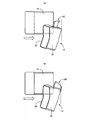
図1は、本発明の一実施例であるもぐり込み防止部材10が車両前部のバンパービーム12に取り付けられた場合を説明する図で、(a) はバンパービーム12をバリア(衝突物)14と共に示す平面図、(b) は(a) におけるIB−IB断面の拡大図、(c) はバンパービーム12のうちもぐり込み防止部材10が取り付けられた中央部分を斜め前上方から見た斜視図である。このバンパービーム12は、その左右の両端部近傍において左右のサイドメンバー16L、16Rの前端部に図示しないクラッシュボックス等を介してボルト等により一体的に固設されており、車両幅方向に略水平となる姿勢で配設されるとともに、バンパービーム12には合成樹脂等から成るバンパー本体18が一体的に取り付けられる。バンパービーム12は、バンパーのリインフォースメント(補強部材)および取付部材として機能するもので、例えば高張力鋼板によって構成され、本実施例では断面が上下方向に長い長方形の角筒形状を成しており、略垂直な前壁20および後壁22、それ等の前壁20、後壁22の上下両端部をそれぞれ接続する略水平な上壁24および下壁26を一体に備えているとともに、図1(a) に示す平面視において左右方向(長手方向)の中央部分が滑らかに前方へ突き出す湾曲形状を成している。前壁20は、車両外側向きの略垂直な外側壁に相当し、上壁24および下壁26は水平壁に相当する。
Hereinafter, embodiments of the present invention will be described in detail with reference to the drawings.
FIG. 1 is a view for explaining a case in which an anti-roll-in
もぐり込み防止部材10は、バンパービーム12の上方へ突き出すようにそのバンパービーム12に一体的に固設されており、バンパービーム12がバリア14の下にもぐり込むことにより、言い換えればバリア14がバンパービーム12の上に乗り上げることにより、ラジエーター等の車両部品に干渉してその車両部品が損傷することを防止するためのものである。もぐり込み防止部材10は、バンパービーム12の車両幅方向の中央部分に所定の幅寸法を有して左右対称に配設されている。
The
もぐり込み防止部材10は、バンパービーム12の前壁20に面接触するように一体的に固設される縦板部30と、その縦板部30が上壁24よりも上方へ突き出す突出端から車両内方(後方側)へ向かうように略直角に折り曲げられた補強板部32と、その補強板部32の車両幅方向の両端からそれぞれ車両幅方向の外側へ向かって連続して一体に設けられた一対の側板部34L、34Rとを備えている。縦板部30は、上壁24よりも上方へ所定の突出寸法だけ突き出しているとともに、車両幅方向に所定の幅寸法を備えている。この突出寸法および幅寸法は、例えば保護すべきラジエーター等の車両部品の高さや幅寸法等を考慮して適宜設定される。縦板部30はまた、バンパービーム12の前壁20に沿って湾曲させられ、その下端部が車両幅方向の全域に亘って前壁20に密着させられているとともに、車両幅方向に延びる下端縁がアーク溶接等による隅肉溶接で前壁20に一体的に溶接接合されている。図1(b) 、(c) の溶接接合部W1は、この縦板部30の下端縁が前壁20に溶接接合された部分で、本実施例では車両幅方向に所定の間隔を隔てて断続的に溶接接合されている。
The anti-roll-in
上記補強板部32は、バンパービーム12の上壁24と略平行に車両後方側へ延び出しているが、縦板部30からの車両後方側への延び出し寸法hは上壁24の幅寸法dよりも短く、例えば図2(a) に示すように相対的にバリア14に衝突してバンパービーム12が変形した場合の、もぐり込み防止部材10の車両内方への侵入が抑制される。すなわち、図2(b) に示すもぐり込み防止部材100のように、断面コの字形状でバンパービーム12の上端部を跨ぐように配設され、その両側の開口端部がそれぞれバンパービーム12の前後壁20、22に一体的に固設される場合、バンパービーム12の変形に伴ってもぐり込み防止部材100の突出端がバンパービーム12よりも車両内方へ侵入し、もぐり込み防止部材100の存在により却ってラジエーター等の車両部品と干渉して損傷する可能性が高くなる場合がある。これに対し、本実施例のもぐり込み防止部材10によれば、補強板部32が前側の縦板部30に片持ち状に設けられるとともに、延び出し寸法hが上壁24の幅寸法dよりも短くされることにより、そのような車両内方への侵入が抑制されて車両部品の損傷が一層適切に抑制される。また、この補強板部32は、略45°の角度で傾斜した小さな幅寸法の平坦な前後傾斜部36を介して縦板部30に接続されており、プレスによる曲げ加工乃至は絞り加工により縦板部30に対して補強板部32が曲げ成形される際の成形性が向上させられている。
The reinforcing
前記一対の側板部34L、34Rは対称的に構成されており、それぞれ補強板部32から車両幅方向の外側へ向かうに従って上壁24に徐々に接近するように下方へ傾斜させられた横傾斜部38と、その上壁24と平行とされて面接触させられる密着部40とを備えている。密着部40の外端縁は車両前後方向に延びており、その外端縁においてアーク溶接等による隅肉溶接で上壁24に一体的に溶接接合されている。図1(c) の溶接接合部W2は、この密着部40の外端縁が上壁24に溶接接合された部分で、本実施例では密着部40の外端縁が車両前後方向の全域に亘って上壁24に溶接接合されている。
The pair of
一方、前記縦板部30は、車両幅方向において上記一対の側板部34L、34Rの外端縁に達する長さ寸法を有し、車両幅方向の全域でその一対の側板部34L、34Rおよび前記補強板部32に一体に接続されており、車両幅方向の全域に亘って略L字形断面を成している。このように車両幅方向の全域に亘って縦板部30と、補強板部32および一対の側板部34L、34Rとが一体に接続されている本実施例のもぐり込み防止部材10は、全体が1枚の金属板材にプレスによる曲げ加工や絞り加工等が施されることにより一体に構成されており、簡単且つ安価に製造できる。金属板材としては、例えばバンパービーム12と同程度の張力を有する高張力鋼板が好適に用いられる。
On the other hand, the
このような本実施例のもぐり込み防止部材10によれば、バンパービーム12の前壁20に一体的に溶接接合される縦板部30と、その縦板部30の突出端から連続して一体に設けられた補強板部32と、その補強板部32の車両幅方向の両端から連続して一体に設けられてバンパービーム12の上壁24に一体的に溶接接合される一対の側板部34L、34Rとから成り、上壁24よりも上方に突き出す縦板部30によってもぐり込みが防止される。
According to such a
ここで、縦板部30の突出端には車両内方へ向かうように略直角に折り曲げられた補強板部32が設けられているため、剛性が高められるとともに、その補強板部32の両端部に設けられた一対の側板部34L、34Rはそれぞれバンパービーム12の上壁24に一体的に溶接接合されているため、縦板部30および補強板部32の変形が抑制され、もぐり込みが一層適切に防止される。その場合に、補強板部32の車両後方側への延び出し寸法hは上壁24の幅寸法dよりも短いため、図2(a) に示すように相対的にバリア14に衝突してバンパービーム12が車両内方側へ変形した場合に、補強板部32がバンパービーム12よりも車両内方側へ侵入してラジエーター等の車両部品と干渉し、その車両部品を損傷する可能性が低くなる。
Here, the protruding end of the
また、このように縦板部30、補強板部32、および一対の側板部34L、34Rから成る本実施例のもぐり込み防止部材10は、1枚の金属板材に対してプレスによる曲げ加工や絞り加工等を施すだけで簡単に構成することができるため、前記特許文献1記載の装置のように重ね合わせて接合する場合に比較して簡単且つ安価に製造することができる。
Further, the anti-roll-in
また、本実施例では、一対の側板部34L、34Rがそれぞれ横傾斜部38および密着部40を備えており、その密着部40がバンパービーム12の上壁24に一体的に溶接接合されるため、バンパービーム12に対する側板部34L、34Rの固設強度が高くなり、もぐり込み防止部材10の剛性が高くなるとともにバンパービーム12に強固に固設されるようになってもぐり込みを一層適切に防止できる。
In the present embodiment, the pair of
また、本実施例では、縦板部30が車両幅方向において一対の側板部34L、34Rの外端縁に達する長さ寸法を有し、車両幅方向の全域で補強板部32および一対の側板部34L、34Rに一体に接続され、車両幅方向の全域に亘って略L字形断面を成しているため、もぐり込み防止部材10の剛性が高くなってもぐり込みを一層適切に防止できる。また、一対の側板部34L、34Rが上壁24に徐々に接近するように傾斜させられているため、プレス加工性が良くなるとともに、もぐり込み防止部材10全体が1枚の金属板材に対するプレス加工(絞り加工など)により一体に構成されているため、簡単且つ安価に製造されて製造コストが低減される。
In the present embodiment, the
また、本実施例では、縦板部30と補強板部32との接続部分に前後傾斜部36が設けられているため、もぐり込み防止部材10を1枚の金属板材からプレス加工によって成形する場合に、そのプレス成形性が向上し、安価な金属板材の採用やプレス金型の耐久性向上等により製造コストを一層低減できる。
Further, in this embodiment, since the front and rear
なお、上記実施例のもぐり込み防止部材10は、縦板部30が車両幅方向において一対の側板部34L、34Rの外端縁に達する長さ寸法を有し、車両幅方向の全域で補強板部32および一対の側板部34L、34Rに一体に接続されていたが、図3の(a) に示すもぐり込み防止部材50のように、車両幅方向において縦板部30と補強板部32とが略同じ幅寸法で、その補強板部32から車両幅方向の外側へ突き出すように一対の側板部34L、34Rが設けられても良い。この場合には、もぐり込み防止50の軽量化を図ることができる。
Note that the anti-roll-in
図3の(b) に示すもぐり込み防止部材52は、上記もぐり込み防止部材50に比較し、補強板部32の車両幅方向の両端部を除いて切欠54が設けられ、補強板部32の車両後方側への延び出し寸法hが更に短くされた場合である。この場合には、更に軽量に構成することができるとともに、図2(a) に示すように相対的にバリア14に衝突してバンパービーム12が車両内方側へ変形した場合に、もぐり込み防止部材52の車両内方側への侵入が一層抑制され、車両部品を損傷する可能性が一層低くなる。
The anti-roll-in
図4は、前記図1の実施例に比較して、もぐり込み防止部材10と上下対称に構成されたもぐり込み防止部材60が、バンパービーム12の下方側にもぐり込み防止部材10と対称的に一体的に溶接固定されている場合で、バリア14がバンパービーム12の下にもぐり込むことにより、言い換えればバンパービーム12がバリア14の上に乗り上げることにより、ラジエーター等の車両部品に干渉してその車両部品が損傷することを防止することができる。上側のもぐり込み防止部材10に替えて下側のもぐり込み防止部材60を取り付けるだけでも良い。
FIG. 4 shows that, compared with the embodiment shown in FIG. 1, the
以上、本発明の実施例を図面に基づいて詳細に説明したが、これ等はあくまでも一実施形態であり、本発明は当業者の知識に基づいて種々の変更,改良を加えた態様で実施することができる。 As mentioned above, although the Example of this invention was described in detail based on drawing, these are one embodiment to the last, and this invention is implemented in the aspect which added the various change and improvement based on the knowledge of those skilled in the art. be able to.
10、50、52、60:もぐり込み防止部材 12:バンパービーム 20:前壁(外側壁) 24:上壁(水平壁) 26:下壁(水平壁) 30:縦板部 32:補強板部 34L、34R:側板部 36:前後傾斜部 38:横傾斜部 40:密着部 W1、W2:溶接接合部
10, 50, 52, 60: Roll-in prevention member 12: Bumper beam 20: Front wall (outer wall) 24: Upper wall (horizontal wall) 26: Lower wall (horizontal wall) 30: Vertical plate portion 32:
Claims (3)
前記外側壁に面接触するように一体的に固設され、前記水平壁よりも上下方向へ所定の突出寸法だけ突き出すとともに、車両幅方向に所定の幅寸法を有する縦板部と、
該縦板部の突出端から連続して車両内方へ向かうように折り曲げられ、前記水平壁から離間して片持ち状に該縦板部の突出端に一体に設けられるとともに、車両前後方向の寸法が前記水平壁よりも短い補強板部と、
該補強板部の車両幅方向の両端からそれぞれ該車両幅方向の外側へ向かって連続して一体に設けられるとともに、前記水平壁に徐々に接近するように傾斜させられ、外端部において該水平壁に一体的に固設される一対の側板部と、
を有することを特徴とする車両用バンパービームのもぐり込み防止部材。 It has a substantially vertical outer wall facing the outside of the vehicle, and a horizontal wall provided substantially horizontally from the vertical end of the outer wall to the inside of the vehicle, and is substantially in the vehicle width direction at the front or rear of the vehicle. A bumper beam for a vehicle bumper beam that prevents a squeeze-in even if it is integrally fixed to the bumper beam so as to protrude vertically from the horizontal wall with respect to the bumper beam disposed horizontally,
A vertical plate portion that is integrally fixed so as to be in surface contact with the outer wall, protrudes in a vertical direction from the horizontal wall by a predetermined protruding dimension, and has a predetermined width dimension in the vehicle width direction;
Bent towards the vehicle both inwardly continuously from the protruding end of the vertical plate portion is provided in an integrally protruding end of the vertical plate portion spaced apart by cantilevered from said horizontal wall, the vehicle front-rear direction A reinforcing plate portion whose dimensions are shorter than the horizontal wall;
The reinforcing plate portion is provided integrally and continuously from both ends in the vehicle width direction toward the outside in the vehicle width direction, and is inclined so as to gradually approach the horizontal wall. A pair of side plates integrally fixed to the wall;
A bumper beam preventive member for a vehicle bumper beam.
ことを特徴とする請求項1に記載の車両用バンパービームのもぐり込み防止部材。 The pair of side plate portions includes a laterally inclined portion that is inclined in the vertical direction so as to gradually approach the horizontal wall, and a close contact portion that is parallel to the horizontal wall and is in surface contact with the horizontal wall. The vehicle bumper beam trapping prevention member according to claim 1, wherein the portion is integrally fixed to the horizontal wall.
全体が1枚の金属板材に対するプレス加工により一体に構成されている
ことを特徴とする請求項1または2に記載の車両用バンパービームのもぐり込み防止部材。 The vertical plate portion has a length dimension that reaches the outer edge of the pair of side plate portions in the vehicle width direction, and is integrally connected to the pair of side plate portions and the reinforcing plate portion in the entire region in the vehicle width direction, A substantially L-shaped cross section is formed over the entire area in the vehicle width direction,
The bumper beam anti-roll-in member for a vehicle according to claim 1 or 2, wherein the whole is integrally formed by pressing a single metal plate.
Priority Applications (4)
| Application Number | Priority Date | Filing Date | Title |
|---|---|---|---|
| JP2010009506A JP5481005B2 (en) | 2010-01-19 | 2010-01-19 | Member for preventing bumping of bumper beam for vehicle |
| US13/008,391 US8128150B2 (en) | 2010-01-19 | 2011-01-18 | Underrun prevention member for vehicle bumper beam |
| EP11151247A EP2345560B1 (en) | 2010-01-19 | 2011-01-18 | Underrun prevention member for vehicle bumper beam |
| CN201110041810.8A CN102126473B (en) | 2010-01-19 | 2011-01-19 | Underrun prevention member for vehicle bumper beam |
Applications Claiming Priority (1)
| Application Number | Priority Date | Filing Date | Title |
|---|---|---|---|
| JP2010009506A JP5481005B2 (en) | 2010-01-19 | 2010-01-19 | Member for preventing bumping of bumper beam for vehicle |
Publications (2)
| Publication Number | Publication Date |
|---|---|
| JP2011148343A JP2011148343A (en) | 2011-08-04 |
| JP5481005B2 true JP5481005B2 (en) | 2014-04-23 |
Family
ID=43838143
Family Applications (1)
| Application Number | Title | Priority Date | Filing Date |
|---|---|---|---|
| JP2010009506A Expired - Fee Related JP5481005B2 (en) | 2010-01-19 | 2010-01-19 | Member for preventing bumping of bumper beam for vehicle |
Country Status (4)
| Country | Link |
|---|---|
| US (1) | US8128150B2 (en) |
| EP (1) | EP2345560B1 (en) |
| JP (1) | JP5481005B2 (en) |
| CN (1) | CN102126473B (en) |
Families Citing this family (12)
| Publication number | Priority date | Publication date | Assignee | Title |
|---|---|---|---|---|
| EP2082924B1 (en) * | 2008-01-22 | 2010-11-03 | Peguform Gmbh | Bumper for motor vehicles |
| US8408636B1 (en) * | 2011-11-15 | 2013-04-02 | Toyota Motor Corporation | Motor vehicles having bumper counter rotation brackets |
| JP5741624B2 (en) | 2013-04-05 | 2015-07-01 | トヨタ自動車株式会社 | Vehicle end structure |
| KR20150049290A (en) * | 2013-10-29 | 2015-05-08 | 현대자동차주식회사 | Tubular back beam for vehicle and manufacturing method thereof |
| US10464512B2 (en) * | 2015-07-31 | 2019-11-05 | Sabic Global Technologies B.V. | Beam with torsional deformation and multi-geometry cross-section |
| US10443239B2 (en) * | 2016-12-02 | 2019-10-15 | Columbia Insurance Company | Long span masonry lintel support system |
| US10480197B2 (en) | 2017-04-04 | 2019-11-19 | Columbia Insurance Company | Masonry support |
| US10308199B2 (en) * | 2017-10-05 | 2019-06-04 | Ford Global Technologies, Llc | Vehicle and vehicle bumper |
| DE102019206434B4 (en) | 2019-05-06 | 2024-03-14 | Volkswagen Aktiengesellschaft | Body structure for a two-track vehicle |
| JP7272991B2 (en) * | 2020-04-14 | 2023-05-12 | トヨタ自動車株式会社 | vehicle |
| KR102503557B1 (en) * | 2020-12-30 | 2023-02-23 | 중부대학교 산학협력단 | Bumper frame that reinforces the rigidity of a horizontal beam |
| FR3133038A1 (en) * | 2022-02-28 | 2023-09-01 | Psa Automobiles Sa | BEAM FOR A FRONT OR REAR PART OF A VEHICLE COMPRISING A LOWER CENTRAL REINFORCEMENT PIECE |
Family Cites Families (17)
| Publication number | Priority date | Publication date | Assignee | Title |
|---|---|---|---|---|
| JP2516214Y2 (en) * | 1991-01-30 | 1996-11-06 | いすゞ自動車株式会社 | Bumper beam structure for automobiles |
| US5560662A (en) * | 1993-12-29 | 1996-10-01 | Boda Industries, Inc. | Vehicle bumper cover |
| JP2001138840A (en) * | 1999-11-12 | 2001-05-22 | Suzuki Motor Corp | Bumper disposition part structure |
| JP3794966B2 (en) * | 2002-02-27 | 2006-07-12 | ユニプレス株式会社 | Bumper reinforcement structure |
| KR100506757B1 (en) * | 2002-10-09 | 2005-08-08 | 현대자동차주식회사 | Bumper beam reinforcement structure |
| JP2004262300A (en) * | 2003-02-28 | 2004-09-24 | Kobe Steel Ltd | Bumper reinforcement |
| US7510232B2 (en) * | 2005-04-01 | 2009-03-31 | Nissan Technical Center North America, Inc. | Bumper with an override feature |
| JP5175448B2 (en) * | 2006-03-29 | 2013-04-03 | アイシン精機株式会社 | Automotive bumper equipment |
| JP4471307B2 (en) * | 2006-04-20 | 2010-06-02 | 本田技研工業株式会社 | Body front structure |
| JP4876822B2 (en) * | 2006-09-27 | 2012-02-15 | マツダ株式会社 | Rear bumper structure of automobile |
| US7533912B2 (en) * | 2007-06-12 | 2009-05-19 | Ford Global Technologies, Llc | Hybrid energy absorber for automobile bumper |
| JP4256436B2 (en) * | 2007-06-22 | 2009-04-22 | 本田技研工業株式会社 | Bumper beam structure |
| WO2009101981A1 (en) * | 2008-02-13 | 2009-08-20 | Nikkeikin Aluminium Core Technology Company Ltd. | Bumper structure |
| KR100974748B1 (en) * | 2008-05-16 | 2010-08-06 | 현대자동차주식회사 | Back beam structure of automobile bumper |
| US20090315346A1 (en) * | 2008-06-20 | 2009-12-24 | David William Schelberg | Bumper reinforcement extension |
| JP5077103B2 (en) | 2008-06-30 | 2012-11-21 | 株式会社豊田中央研究所 | Advice information presentation device and program |
| US7954866B2 (en) * | 2008-07-03 | 2011-06-07 | Honda Motor Co., Ltd. | Bumper beam with gussets to prevent underride |
-
2010
- 2010-01-19 JP JP2010009506A patent/JP5481005B2/en not_active Expired - Fee Related
-
2011
- 2011-01-18 EP EP11151247A patent/EP2345560B1/en not_active Not-in-force
- 2011-01-18 US US13/008,391 patent/US8128150B2/en not_active Expired - Fee Related
- 2011-01-19 CN CN201110041810.8A patent/CN102126473B/en not_active Expired - Fee Related
Also Published As
| Publication number | Publication date |
|---|---|
| US8128150B2 (en) | 2012-03-06 |
| JP2011148343A (en) | 2011-08-04 |
| EP2345560B1 (en) | 2013-03-20 |
| CN102126473A (en) | 2011-07-20 |
| CN102126473B (en) | 2014-10-22 |
| EP2345560A1 (en) | 2011-07-20 |
| US20110175380A1 (en) | 2011-07-21 |
Similar Documents
| Publication | Publication Date | Title |
|---|---|---|
| JP5481005B2 (en) | Member for preventing bumping of bumper beam for vehicle | |
| JP6866831B2 (en) | Vehicle front body structure | |
| JP5245674B2 (en) | Body structure | |
| KR101766749B1 (en) | Vehicle side structure | |
| JP7156164B2 (en) | vehicle front structure | |
| US10836436B2 (en) | Vehicle body frame structure | |
| JP7115414B2 (en) | vehicle front structure | |
| JP2019018600A (en) | Vehicle body structure | |
| JP5692119B2 (en) | Vehicle cowl structure | |
| US10689035B2 (en) | Side rail and manufacturing method of side rail | |
| JP6254448B2 (en) | Bumper beam for vehicles | |
| JP2014189200A (en) | Bumper coupling structure and crash box | |
| JP5949532B2 (en) | Rear bumper reinforcement structure and vehicle rear structure | |
| JP2020117159A (en) | Vehicle structure | |
| JP4469153B2 (en) | Automotive bumper equipment | |
| CN110884567B (en) | Front body structure of vehicle | |
| JP4751901B2 (en) | Automotive bumper equipment | |
| JP4798485B2 (en) | Vehicle front bumper structure | |
| JP2013226867A (en) | Body front structure of automobile | |
| JP7228134B2 (en) | Underrun protector structure | |
| JP7144529B2 (en) | bumper crash box | |
| JP2008132830A (en) | Front part structure for vehicle | |
| JP4505514B2 (en) | Automotive bumper equipment | |
| JP7397025B2 (en) | Vehicle rear structure | |
| JP6533955B2 (en) | Vehicle structure |
Legal Events
| Date | Code | Title | Description |
|---|---|---|---|
| A621 | Written request for application examination |
Free format text: JAPANESE INTERMEDIATE CODE: A621 Effective date: 20120316 |
|
| A977 | Report on retrieval |
Free format text: JAPANESE INTERMEDIATE CODE: A971007 Effective date: 20130709 |
|
| A131 | Notification of reasons for refusal |
Free format text: JAPANESE INTERMEDIATE CODE: A131 Effective date: 20130723 |
|
| A521 | Written amendment |
Free format text: JAPANESE INTERMEDIATE CODE: A523 Effective date: 20130918 |
|
| TRDD | Decision of grant or rejection written | ||
| A01 | Written decision to grant a patent or to grant a registration (utility model) |
Free format text: JAPANESE INTERMEDIATE CODE: A01 Effective date: 20140128 |
|
| A61 | First payment of annual fees (during grant procedure) |
Free format text: JAPANESE INTERMEDIATE CODE: A61 Effective date: 20140215 |
|
| R150 | Certificate of patent or registration of utility model |
Ref document number: 5481005 Country of ref document: JP Free format text: JAPANESE INTERMEDIATE CODE: R150 |
|
| LAPS | Cancellation because of no payment of annual fees |