JP5480603B2 - Wiring inlet device - Google Patents
Wiring inlet device Download PDFInfo
- Publication number
- JP5480603B2 JP5480603B2 JP2009272643A JP2009272643A JP5480603B2 JP 5480603 B2 JP5480603 B2 JP 5480603B2 JP 2009272643 A JP2009272643 A JP 2009272643A JP 2009272643 A JP2009272643 A JP 2009272643A JP 5480603 B2 JP5480603 B2 JP 5480603B2
- Authority
- JP
- Japan
- Prior art keywords
- cover
- cap
- plate
- base
- front plate
- Prior art date
- Legal status (The legal status is an assumption and is not a legal conclusion. Google has not performed a legal analysis and makes no representation as to the accuracy of the status listed.)
- Active
Links
Images


Landscapes
- Insulating Bodies (AREA)
- Details Of Indoor Wiring (AREA)
Description
本発明は、配線を引き込むための配線引込口装置に関するものである。 The present invention relates to a wiring inlet device for drawing a wiring.
従来から、屋外の配線を屋内に引き込むために、造営面に配線引込口装置が設けられる(例えば特許文献1参照)。 Conventionally, in order to draw outdoor wiring indoors, a wiring inlet device is provided on the construction surface (see, for example, Patent Document 1).
配線引込口装置は、図5に示すように、略箱状をした本体ケーシングで外殻が構成され、本体ケーシングの屋外に面する部分に引込口面となるキャップ3が嵌め込まれ、本体ケーシングの屋内に面する部分に電線管接続部27が形成される。キャップ3は、板状本体31の周縁から筒部32が連設されるもので、板状本体31の表裏に貫通する電線挿通孔30が一つ又は複数形成してある。
As shown in FIG. 5, the wiring inlet device includes a substantially box-shaped main body casing and an outer shell, and a
本体ケーシングは、それぞれ二つ割れの半体となるカバー1とベース2とからなり、カバー1のベース2と接合される接合端縁に挿通口10が切欠してあると共に、ベース2の前記切欠に対応する部分の端縁部に係止部5が形成してある。キャップ3は、その周端縁をベース2の係止部5に係止し、カバー1とベース2の接合端縁同士を接合して固定し、カバー1に形成してある係合部4にキャップ3の周端縁を係合させ、ベース2の係止部5とカバー1の係合部4とでキャップ3を挟持するようになっている。
The main body casing is composed of a
しかしながら、従来においては、キャップ3の下端縁をベース2の係止部5に係止し、その後、カバー1を上方より被せてベース2に接合してカバー1の係合部4にキャップ3の上端縁を係合させるまで、キャップ3は下端縁が係止部5で係止されるのみで上端縁が自由端となって動き得るものであった。このため、キャップ3の下端縁が係止部5で係止されただけの状態でキャップ3に触れたりするとキャップ3が倒れてしまい、再び、キャップ3の下端縁をベース2の係止部5に係止するところからやり直さなければならず、組み立ての作業性が悪いものであった。
However, conventionally, the lower end edge of the
本発明は上記従来の問題点に鑑みて発明したものであって、その目的とするところは、キャップの下端縁をベースの係止部に係止した状態で、カバーを上方より被せてベースに接合して固定する際、キャップが倒れ難く組み立て作業性が良い配線引込口装置を提供することを課題とするものである。 The present invention has been invented in view of the above-mentioned conventional problems, and the object of the present invention is to cover the base with the cover from above with the lower end edge of the cap locked to the locking portion of the base. It is an object of the present invention to provide a wiring inlet device that is easy to be assembled and is easy to assemble when joining and fixing.
上記課題を解決するために、本発明は、以下のような構成とする。 In order to solve the above problems, the present invention has the following configuration.
外殻となる本体ケーシングが二つ割れの半体であるカバー1とベース2とからなり、カバー1は、配線が挿通される挿通口10を有する前板部11と、前板部11と隣接し両側方をそれぞれ覆う側板部12と、上方と背方とを覆う覆い部13とからなり、ベース2は、上方に開口しそれぞれ前後左右を向く前板22と左右両側板23と背板24とからなる筒部21と、筒部21の下端縁から内方に連設される筒底部25と、筒底部25の内端縁から下方に連設され上方に開口する下箱部26と、からなり、下箱部26に電線管が接続される電線管接続部27を備え、前記配線が挿通される挿通口10に電線挿通孔30を備えたキャップ3を設けてなる配線引込口装置である。ベース2の筒部21の左右両側板23の前板22背面から背方にキャップ3の前後方向の厚みt分を隔てた位置に係止リブ51を形成すると共に、カバー1の側板部12の内面の前板部11背面から背方にキャップ3の前後方向の厚みt分を隔てた位置に保持リブ6を形成する。
The main body casing, which is an outer shell, is composed of a
本発明にあっては、キャップの側端縁が保持リブと前板部とで挟まれて前後に倒れるのが防止され、組み立て作業性が向上するものである。 In the present invention, it is possible to prevent the side edge of the cap from being sandwiched between the holding rib and the front plate portion and to fall forward and backward, and to improve the assembly workability.
また、キャップをベースやカバーにねじ固定することなく固定することができる。 Further, the cap can be fixed to the base or cover without screwing.
以下、屋外の配線を屋内に引き込むために造営面に設けられる本発明の配線引込口装置について、添付図面に示す実施形態に基いて説明する。 Hereinafter, the wiring inlet apparatus of the present invention provided on the construction surface for drawing outdoor wiring indoors will be described based on embodiments shown in the accompanying drawings.
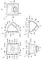
配線引込口装置は、図1に示すように、それぞれ二つ割れの半体となるカバー1とベース2とからなり、組み立てると略箱状となる本体ケーシングで外殻が構成される。本体ケーシングには、屋外に面する部分に引込口面となるキャップ3が設けられると共に、屋内に面する部分に電線管接続部27が形成される。以下の説明では、便宜上、引込口面が向く方を前方とすると共に、電線管接続部27が設けられる方を下方とする。図1(a)は配線引込口装置の正面図、(d)は側断面図である。
As shown in FIG. 1, the wiring inlet device is composed of a
カバー1は、図2に示すように、下方に開口する略コ字状をした前板部11と(図2(a)参照、左右側方をそれぞれ覆う側板部12と、上方や背方を覆う覆い部13(天板部13a)からなるもので、前方の大部分と下方に向けて開口している。そして、この前板部11の略コ字状に囲まれる切欠は、引き込まれる配線が挿通される挿通口10となる。本実施形態では挿通口10は切欠であるが、前板部11の内部が開口されて略ロ字状をしていて、この内部の開口を挿通口10としてもよいものである。また、覆い部13は、本実施形態では上方及び背方を覆う天板部13aとなっているが、上方を覆う天板部と背方を覆う背板部とが連続せず別になっていてもよい。
As shown in FIG. 2, the
側板部12の背方側の上部は図2(c)や(d)に示すように、略円弧状をしており、天板部13aの背方側の部分も前記略円弧状に対応して略円筒状の曲面となっている。側板部12の前後方向中央部の下端部近傍には、ビスからなる固着具15が挿通される固着具挿通孔14が穿設してある。
As shown in FIGS. 2C and 2D, the upper portion on the back side of the
天板部13aには、キャップ3を保持する係合部4として、前板部11の背面から背方にキャップ3の前後方向の厚みt(図4(b)参照)分を隔てた位置に係合リブ41が形成してある。また、側板部12には本発明の保持リブ6が設けられるもので、これについては後述する。
The
上記前板部11と側板部12と天板部13aの下端部が、ベース2と接合される。なお本実施形態では、カバー1は鋳鉄製とするが特に鋳鉄に限定されるものではなく、他の金属やその他の材質であってもよい。
The lower end portions of the
ベース2は、図3に示すように、上方に開口し前後左右を向く前板22と左右両側板23と背板24とからなる略矩形状をした筒部21と、筒部21の下端縁から内方に連設される平面視略ロ字状をした略板状の筒底部25と、筒底部25の内端縁から下方に連設される、上方に開口した略箱状の下箱部26と、からなるものである。下箱部26は更に、前縦板26aと、後縦板26bと、前縦板26aの下端から下斜め背方略45°の方向に向けて連設される前斜板26cと、後縦板26bの下端から下斜め前方略45°の方向に向けて連設される後斜板26dと、前記前縦板26a、後縦板26b、前斜板26c、後斜板26dの側端に接続される左右両側板26eと、で構成される。下箱部26には可撓管等の電線管が被嵌されて接続される、略筒状をした電線管接続部27が形成されるもので、本実施形態では前斜板26cから下斜め前方略45°の方向に向けて電線管接続部27が突設してあるが、特に略45°に限定されない。また下箱部26は、前縦板26a及び後縦板26bがなく前斜板26cと後斜板26dと左右両側板26eのみで構成されていたり、あるいは全体が連続した曲面で構成されていたりしてもよく、形状は限定されない。なお本実施形態では、ベース2は鋳鉄製とするが特に鋳鉄に限定されるものではなく、他の金属やその他の材質であってもよい。
As shown in FIG. 3, the
上記筒部21がカバー1と接合されるもので、上方よりカバー1が被嵌されて、筒部21の左右両側板23の外側にカバー1の側板部12が位置すると共に、筒部21の背板24の外側にカバー1の天板部13aの背方側の端部が位置し、また、筒部21の前板22の上端縁は、カバー1の前板部11の下端と突き合わされる状態となる。
The
筒部21の左右両側板23には、カバー1が被嵌された時にカバー1の側板部12の固着具挿通孔14と連通するように、前後方向中央部に、ビスからなる固着具15が螺着される固着孔28が螺設してある。また筒部21の左右両側板23には、キャップ3を保持する係止部5として、筒部21の前板22の背面から背方にキャップ3の前後方向の厚みt分を隔てた位置に係止リブ51が形成してある。
The left and
更に本実施形態では、左右両側板23に、キャップ3を保持する係止部5として、筒部21の背板24の前面から前方にキャップ3の前後方向の厚みt分を隔てた位置にも係止リブ52が形成してある。これにより、カバー1に対してベース2の前後を逆に取り付けることができて、電線挿通孔30の向きを逆にすることが可能となる。
Further, in the present embodiment, the left and
キャップ3は、図4に示すように、正面視略矩形状をした板状本体31と、該板状本体31の周縁から下方に連設される略筒状をした筒部32と、で形成される絶縁材からなるもので、筒部32の厚みがキャップ3の前後方向の厚みtとなる。
As shown in FIG. 4, the
板状本体31には、表裏に貫通する電線挿通孔30が一つ又は複数形成されるもので、電線挿通孔30の数については限定されない。本実施形態では三つの電線挿通孔30が穿設してあり、電線挿通孔30の内端縁からは背方側に向けて環状リブ33が突設してある。
One or a plurality of electric wire insertion holes 30 penetrating the front and back are formed in the plate-shaped
カバー1とベース2とキャップ3の組み立てについて説明すると、まず、キャップ3の下端縁をベース2の係止部5に係止する。すなわち、キャップ3の下端縁を、ベース2の筒部21の側板23に形成した係止リブ51と前板22との間に上方より嵌入し、筒底部25に載置する。
The assembly of the
その後、カバー1を上方より被せていって下端部をベース2の筒部21に被嵌するのであるが、この時、保持リブ6によりキャップ3が倒れないように保持しながら、カバー1を被せていくものである。保持リブ6は、側板部12の内面において、前板部11の背面から背方にキャップ3の前後方向の厚みt分を隔てた位置に形成されるもので、側板部12の上下全長あるいは大部分(略7割以上)に亘って形成されるのが好ましい。本実施形態では側板部12の上端から下端に向けて略4分の3の位置まで形成される。カバー1を上方より被せていくと、キャップ3がカバー1の保持リブ6と前板部11との間に嵌入されて、キャップ3の側端縁が保持リブ6と前板部11とで挟まれて前後に倒れるのが防止される。
Thereafter, the
そして、カバー1の下端部をベース2の筒部21に被嵌すると共に、カバー1の係合部4にキャップ3の上端縁を係合させ、固着具15を固着具挿通孔14に挿通して固着孔28に螺着してカバー1をベース2に固定する。キャップ3は、上端縁はカバー1の係合リブ41と前板部11との間に挟持され、下端縁はベース2の係止リブ51と前板22とで挟持され、側端縁は保持リブ6と前板部11とで挟持され、前後方向が強固に固定される。
Then, the lower end portion of the
上述したように、カバー1の側板部12の内面に保持リブ6を設けたことで、カバー1を上方よりベース2に被せていく際、キャップ3の側端縁が保持リブ6と前板部11とで挟まれて前後に倒れるのが防止され、従来のようにキャップ3の下端縁が係止部5で係止されただけの状態でキャップ3が倒れ易いといったことがなく、カバー1とベース2とキャップ3の組み立て作業性が向上する。
As described above, since the holding
1 カバー
10 挿通口
11 前板部
12 側板部
13 覆い部
14 固着具挿通孔
15 固着具
2 ベース
21 筒部
22 前板
23 側板
24 背板
25 筒底部
26 下箱部
27 電線管接続部
28 固着孔
3 キャップ
30 電線挿通孔
31 板状本体
32 筒部
4 係合部
41 係合リブ
5 係止部
51 係止リブ
52 係止リブ
6 保持リブ
DESCRIPTION OF
Claims (1)
Priority Applications (1)
| Application Number | Priority Date | Filing Date | Title |
|---|---|---|---|
| JP2009272643A JP5480603B2 (en) | 2009-11-30 | 2009-11-30 | Wiring inlet device |
Applications Claiming Priority (1)
| Application Number | Priority Date | Filing Date | Title |
|---|---|---|---|
| JP2009272643A JP5480603B2 (en) | 2009-11-30 | 2009-11-30 | Wiring inlet device |
Publications (2)
| Publication Number | Publication Date |
|---|---|
| JP2011120314A JP2011120314A (en) | 2011-06-16 |
| JP5480603B2 true JP5480603B2 (en) | 2014-04-23 |
Family
ID=44284963
Family Applications (1)
| Application Number | Title | Priority Date | Filing Date |
|---|---|---|---|
| JP2009272643A Active JP5480603B2 (en) | 2009-11-30 | 2009-11-30 | Wiring inlet device |
Country Status (1)
| Country | Link |
|---|---|
| JP (1) | JP5480603B2 (en) |
Families Citing this family (2)
| Publication number | Priority date | Publication date | Assignee | Title |
|---|---|---|---|---|
| CN104900349B (en) * | 2015-06-01 | 2017-01-25 | 长沙伊联盾电力科技有限公司 | Insulating sheath on the upper end of an electric pole stay wire in an electric power system, and fixing device thereof |
| JP6843532B2 (en) * | 2016-07-01 | 2021-03-17 | 株式会社三桂製作所 | Entrance cap |
-
2009
- 2009-11-30 JP JP2009272643A patent/JP5480603B2/en active Active
Also Published As
| Publication number | Publication date |
|---|---|
| JP2011120314A (en) | 2011-06-16 |
Similar Documents
| Publication | Publication Date | Title |
|---|---|---|
| US10342154B2 (en) | Power supply apparatus | |
| JP3121508U (en) | Multidirectional outlet with cover | |
| USD637890S1 (en) | Cover plate for in-wall mounted electronic component housing | |
| USD577280S1 (en) | Wall plate and cover assembly | |
| CA2600756A1 (en) | Snap fit screw plug | |
| WO2018092646A1 (en) | Charging inlet | |
| JP5480603B2 (en) | Wiring inlet device | |
| JP2012013149A (en) | Packing structure | |
| KR20110073662A (en) | Electricityswitch box buying a model for a building | |
| JP2022002221A (en) | Storage battery unit | |
| JP2014145567A (en) | Outdoor unit of air conditioner | |
| JP5107026B2 (en) | Air conditioner outdoor unit | |
| CN202487679U (en) | Lithium ion battery case | |
| JP2012033826A (en) | Housing | |
| JP5759812B2 (en) | Cover connection structure and cover connection method | |
| JP2011158187A (en) | Indoor unit for air conditioner | |
| JP2012132170A (en) | Floor panel | |
| US20060028846A1 (en) | Connection device for solar panels in a solar powered lantern to enable thesolar panels to extend horizontally to the solar powered lantern | |
| WO2018193925A1 (en) | Connector equipped with cover | |
| ATE403963T1 (en) | ELECTRICAL SOCKET WITH RING | |
| JP5740564B2 (en) | Waterproof device for lighting fixtures | |
| JP5691957B2 (en) | Wire cover | |
| JP4266177B2 (en) | Waterproof structure of lighting equipment | |
| JP5914794B2 (en) | lighting equipment | |
| JP6065222B2 (en) | Wiring box |
Legal Events
| Date | Code | Title | Description |
|---|---|---|---|
| A711 | Notification of change in applicant |
Free format text: JAPANESE INTERMEDIATE CODE: A712 Effective date: 20120118 |
|
| A621 | Written request for application examination |
Free format text: JAPANESE INTERMEDIATE CODE: A621 Effective date: 20121109 |
|
| A977 | Report on retrieval |
Free format text: JAPANESE INTERMEDIATE CODE: A971007 Effective date: 20131003 |
|
| TRDD | Decision of grant or rejection written | ||
| A01 | Written decision to grant a patent or to grant a registration (utility model) |
Free format text: JAPANESE INTERMEDIATE CODE: A01 Effective date: 20140121 |
|
| A61 | First payment of annual fees (during grant procedure) |
Free format text: JAPANESE INTERMEDIATE CODE: A61 Effective date: 20140214 |
|
| R150 | Certificate of patent or registration of utility model |
Ref document number: 5480603 Country of ref document: JP Free format text: JAPANESE INTERMEDIATE CODE: R150 |