JP5478366B2 - Video surveillance device - Google Patents
Video surveillance device Download PDFInfo
- Publication number
- JP5478366B2 JP5478366B2 JP2010124248A JP2010124248A JP5478366B2 JP 5478366 B2 JP5478366 B2 JP 5478366B2 JP 2010124248 A JP2010124248 A JP 2010124248A JP 2010124248 A JP2010124248 A JP 2010124248A JP 5478366 B2 JP5478366 B2 JP 5478366B2
- Authority
- JP
- Japan
- Prior art keywords
- image
- area
- monitoring
- overlapping
- depth
- Prior art date
- Legal status (The legal status is an assumption and is not a legal conclusion. Google has not performed a legal analysis and makes no representation as to the accuracy of the status listed.)
- Active
Links
Images


Landscapes
- Closed-Circuit Television Systems (AREA)
- Alarm Systems (AREA)
- Train Traffic Observation, Control, And Security (AREA)
Description
本発明は、監視対象領域を撮影した複数の画像を加工して合成し、一つの合成画像として表示する映像監視装置に関する。 The present invention relates to a video monitoring apparatus that processes and synthesizes a plurality of images obtained by photographing a monitoring target area and displays the images as one synthesized image.
駅のホームの手前および奥行き側の映像(画像)を、異なる位置から重複領域をもつように撮影し、手前側の画像に、奥行き側の画像の大きさを揃え、同じ被写体が同じサイズで表示されるように画像変換した上で、重複領域に所定の透過率で重ね合わせて合成画像を得ていた(例えば、特許文献1参照)。 Video (images) on the near side and depth side of the station platform are shot from different positions with overlapping areas, and the depth side image is aligned with the near side image, and the same subject is displayed in the same size. Then, the image is converted as described above, and a composite image is obtained by superimposing the overlap area with a predetermined transmittance (see, for example, Patent Document 1).
従来の映像監視装置は、監視対象領域の複数の画像を、一つの画像に合成することができるが、奥行き側画像を手前側画像内に小さくはめ込む状態となるため、目視する画面上での奥行き側画像のサイズが小さくなり、目視による観察がしにくくなるという問題があった。 A conventional video monitoring apparatus can combine multiple images of the monitoring target area into one image, but the depth side image is in a state of being fitted into the near side image, so that the depth on the screen to be viewed There is a problem that the size of the side image is reduced, and visual observation is difficult.
本発明は、上記のような問題を解決するためになされたものであり、目視する画面上での奥行き側画像を、目視が容易なサイズに変換するとともに、監視対象領域の欠落部が生じないように、かつ遠近感を解消できるように手前側画像を加工し、合成画像を得ることを目的としている。 The present invention has been made to solve the above-described problem, and converts the depth-side image on the screen to be viewed into a size that is easy to view, and does not cause a missing portion of the monitoring target region. Thus, the object is to process the near-side image so as to eliminate the sense of perspective and obtain a composite image.
この発明に係わる映像監視装置は、監視対象領域である第一の監視エリアを撮影する第一の監視カメラ、上記監視対象領域であり、上記第一の監視エリアとの重複領域を持つ第二の監視エリアを撮影する第二の監視カメラ、上記第一の監視カメラが撮影した上記第一の監視エリアの、第一の画像を取り込み、上記第一の画像を、上記第二の監視エリアと重なる領域を含む重複部と、上記重複部以外の非重複部に分割し、上記重複部を拡大するとともに、上記非重複部を縮小して画像変換を行い、第一の変換画像を得る第一の画像変換部、上記第二の監視エリアの、第二の画像を取り込み、上記第一の変換画像の被写体の大きさに揃えるように、上記第二の画像の表示倍率を変更して画像変換を行い、第二の変換画像を得る第二の画像変換部、上記第一、第二の変換画像を取り込み、上記第一の変換画像の上記重複部に、上記第二の変換画像を重ね合わせた合成画像を得る画像合成処理部、上記合成画像を表示する表示部を備えたものである。 The video monitoring apparatus according to the present invention includes a first monitoring camera that captures a first monitoring area that is a monitoring target area, a second monitoring camera that is the monitoring target area, and has an overlapping area with the first monitoring area. The second monitoring camera that captures the monitoring area, the first image of the first monitoring area captured by the first monitoring camera is captured, and the first image overlaps the second monitoring area. A first part that obtains a first converted image by dividing an overlapping part including a region and a non-overlapping part other than the overlapping part, enlarging the overlapping part, reducing the non-overlapping part, and performing image conversion The image conversion unit captures the second image in the second monitoring area, changes the display magnification of the second image so as to match the subject size of the first converted image, and performs image conversion. A second image conversion unit for obtaining a second converted image, An image composition processing unit that captures the first and second converted images and obtains a composite image in which the second converted image is superimposed on the overlapping portion of the first converted image, and a display that displays the composite image It has a part.
この発明の映像監視装置によれば、第一、第二の画像の重複部と非重複部のそれぞれにおいて拡大、縮小の画像変換をするため、目視が容易なように重複部を拡大した場合においても、非重複部を縮小させる画像変換を行うことができ、表示部上の合成画像に、非重複部を縮小させなかった場合と比べて、より多くの第一の画像の情報を表示することが可能となる。 According to the video monitoring apparatus of the present invention, in order to perform image conversion for enlargement and reduction in each of the overlapping portion and the non-overlapping portion of the first and second images, In addition, image conversion that reduces the non-overlapping part can be performed, and more information about the first image is displayed in the composite image on the display unit than when the non-overlapping part is not reduced. Is possible.
実施の形態1.
次に、この発明の実施の形態1について、図1〜12を用いて説明する。
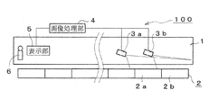
図1は、この発明の映像監視装置を構成する監視カメラが、駅施設のホーム近傍に設置された状態を示す図であり、監視カメラによる監視エリアの撮影状況を示す説明図である。
図1に示すように、ホーム1には列車車両2aと、列車車両2aに連結された列車車両2bが乗り入れられている。図1の図中左側(後述する車掌(モニタ観察者)6および表示部5の位置)から見て、ホーム1の手前側に列車車両2aが、奥行き側に列車車両2bが停止している。これら列車車両2a、2bと、列車の乗降口から乗客が乗り降りするホーム1の領域が、監視対象領域となる。ホーム1の手前側に配置された監視カメラ3aは、主に列車車両2aの乗降口が設けられた側面およびそれ以遠の奥行き側と、向かい合うホーム1を撮像するものであり、ホーム1の奥行き側に配置された監視カメラ3bは、主に列車車両2bの乗降口が設けられた側面と向かい合うホーム1を撮像するものである。このように監視カメラ3a、3bで撮影した場合、監視カメラ3aで撮影する領域(第一の監視エリア)と、監視カメラ3bで撮影する領域(第二の監視エリア)に重複する領域(重複領域)が生じた状態となる。この重複領域上の所定の位置で、第一、第二の監視エリアを撮影して得られる第一、第二の画像を合成する際に被写体のサイズを揃えるように画像変換処理を行うものである。
Next,
FIG. 1 is a diagram showing a state in which the surveillance camera constituting the video surveillance apparatus of the present invention is installed in the vicinity of the platform of the station facility, and is an explanatory diagram showing the photographing situation of the surveillance area by the surveillance camera.
As shown in FIG. 1, a train vehicle 2 a and a train vehicle 2 b connected to the train vehicle 2 a are entered in the
図2に本発明の映像監視装置の概略構成図を、駅施設の配置に関連させて示し、図3に映像監視装置の構成ブロック図を示す。映像監視装置100は、ホーム1およびホーム1に乗り入れた列車2の列車車両2aおよび2bとそれら車両へ乗降するためのホーム1の領域を監視対象としており、監視対象領域の画像を得るための撮像部3は、監視カメラ3a、3bで構成される。より詳しくは、監視対象領域である列車車両2aおよび同車両に乗降するためのホーム1とその周辺並びにそれ以遠の奥行き領域(第一の監視エリア)を撮影する手前側の監視カメラ(第一の監視カメラ)3a、列車車両2bおよび同車両に乗降するためのホーム1とその周辺並びにそれ以遠の奥行きを含む領域であり、第一の監視エリアとの重複領域を持つ領域(第二の監視エリア)を撮影する奥行き側の監視カメラ3b(第二の監視カメラ)によって撮像部3が構成される。
FIG. 2 shows a schematic configuration diagram of the video monitoring apparatus of the present invention in relation to the arrangement of station facilities, and FIG. 3 shows a configuration block diagram of the video monitoring apparatus. The
次に、監視カメラ(第一、第二の監視カメラ)3a、3bにて得た画像データを取り込み、変換処理する画像処理部4について説明する。画像処理部4は、監視カメラ3aが撮影した第一の監視エリアの、第一の画像(手前側画像)を取り込み、その第一の画像を、第二の監視エリアと重なる領域を含む重複部と、重複部以外の非重複部に分割し、重複部
を拡大するとともに、非重複部を縮小して画像変換を行い、第一の変換画像(手前側変換画像)を得る第一の画像変換部(手前側画像変換部)4a、第二の監視エリアの、第二の画像(奥行き側画像)を取り込み、第一の変換画像の被写体の大きさに揃えるように、第二の画像の表示倍率を変更して画像変換を行い、第二の変換画像(奥行き側変換画像)を得る第二の画像変換部(奥行き側画像変換部)4b、第一、第二の変換画像を取り込み、第一の変換画像の重複部に、第二の変換画像を重ね合わせた合成画像を得る画像合成処理部4cによって構成される。
さらに、合成画像を表示する合成画像表示部(表示部)5が、ホーム1上の他端側(すなわち手前側)に立って乗降客の安全確認をする車掌6から目視可能な位置に配置される。なお、手前側画像変換部4aにおいて手前側画像を取り込んで画像変換する場合で、手前側画像に、合成画像として表示する必要がない領域が含まれている時は、表示が必要な領域のみを表示選択領域として残し、不要領域を削除することもでき、奥行き側画像変換部4bの場合も同様に、奥行き側画像の表示領域を選択することが可能である。
Next, the
Further, a composite image display unit (display unit) 5 for displaying a composite image is disposed at a position where the composite image display unit (display unit) 5 can be seen from the
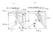
ここで、この発明に到るまでの発明者らによる考察について説明する。図4は本発明の説明に必要な画像合成に関する従来技術を示す図である。図4(a)は監視カメラ3bで撮影した奥行き側画像32を、図4(b)は監視カメラ3aで撮影した手前側画像31をそれぞれ示しており、図4(c)は、手前側画像31を当倍で表示し、奥行き側画像32を縮小して得た奥行き側変換画像32aを、被写体の大きさと位置(重複領域の所定の位置)を揃えて重ね合わせて表示させた場合の合成画像33を示している。合成画像33から分かるように、手前側画像31は当倍で表示されるため、手前側の列車車両2a前のホーム1に立って両手を上に挙げている人物20aは、合成画像内において比較的大きなサイズで表示されるため、車掌6による目視確認が容易であるが、奥行き側の列車車両2b前のホーム1に立って手を下ろしている人物20bは、奥行き側変換画像32aが縮小表示されているために、縮小倍率に従って小さなサイズで表示されるため、車掌6による目視確認がし難いことが分かる。
Here, considerations by the inventors until reaching the present invention will be described. FIG. 4 is a diagram showing a conventional technique related to image composition necessary for explaining the present invention. 4A shows a
そこで、発明者らは、手前側画像31の、奥行き側画像32をはめ込む領域を拡張させることで、奥行き側画像32を、図4(c)の合成画像33で示した奥行き側画像32aより大きな比率となるように表示部5上(合成画像上)に表示できるようにし、監視対象領域の奥行き側の領域における目視を容易にすることについて検討を行った。
図5は本発明の説明に必要な画像合成に関する図であり、手前側画像31の、ホーム1の奥行き側領域を拡大加工する画像変換説明図である。
ホーム1の奥行き側領域を拡大表示するには、図5(a)に示すように、手前側画像31の列車車両2aの奥行き側端部のホーム1と交わる下端部(点B)を、図5(b)に示すように、より下方の点B1に移動させることで、列車車両2aの奥行き側端部の上下方向を拡張させることができ、ホーム1の奥行き側エリアを加工(変換)前よりも広く表示させることが可能となる。
Therefore, the inventors expand the area in which the
FIG. 5 is a diagram relating to image composition necessary for the description of the present invention, and is an image conversion explanatory diagram for enlarging the depth side region of the
In order to enlarge and display the depth side area of the
しかし、図5(a)中の点A、B、C、Dで囲まれた四角形状の領域を、図5(b)中の点A、B1、C、Dで囲まれた四角形状に移動するように、手前側画像31全体の平面射影変換を行うと、図5(c)の手前側変換画像40に示すように、点Bの点B1への移動にあわせてホーム1の手前側が回転を伴なうように大きく歪む。そのため、図5(a)にて表示されていた人物20aより手前側のホーム1の欠落エリア31cが、変換後の手
前側変換画像40には表示されなくなってしまう。なお、ホーム1上の3つの丸印は、変換後の画像の変形を理解しやすくするために付した印であり、ホーム1の長さ方向に垂直な線上(図中、横方向)に、それぞれが離間して配置された印である。この丸印は、変換前の手前側画像31上では、ホーム1上で横一列に表示されているが、変換後の手前側変換画像40上では、ホーム1が回転を伴うように変形することを受けて、3つの丸印の並びが左下側に傾く状態となり、結果的に、奥行き画像を配置するエリアを拡大することは
できたものの、上述のとおり、人物20aの手前の欠落エリア31cは、手前側変換画像34上には表示されなくなってしまうという問題が生じることが分かった。
However, the rectangular area surrounded by the points A, B, C, and D in FIG. 5A is changed to a rectangular area surrounded by the points A, B 1 , C, and D in FIG. When planar projection conversion is performed on the entire
そこで、発明者らは、手前側画像31上での奥行き側画像32に相当する表示領域よりも大きくなるように、奥行き側画像32の表示領域を調節するとともに、図5で示したような欠落エリア31cを発生させることがない画像変換の手法について検討を行い、図1〜図3で示した映像監視装置100を用いることで、それらが可能となることを見出した。
図3の映像監視装置100の構成である画像処理部4での加工手法についてより詳細に説明する。
Therefore, the inventors adjust the display area of the
The processing method in the
監視カメラ3bで撮影した奥行き側画像32を取り込む奥行き側加工処理部4bでは、図4(a)に示した奥行き側画像32のうち、合成画像に表示させたい領域を選択し(表示領域選択)、奥行き側画像の形状を決定する。この処理によって、例えば、ホーム1の終端部よりもさらに奥側となる、ホームが無い領域をカットし、乗客の乗降が見られる領域のみに表示領域を限定することができる。このような表示領域選択処理を行うことで、合成画像上の表示領域を有効に利用することが可能となる。なお、奥行き側画像32の全領域を選択することも可能であることは言うまでもない。そして、次に、選択された奥行き側画像32のサイズを変更し、合成画像上での配置を決定する。このように加工された奥行き側画像32のサイズおよび合成画像上での配置の情報(映像加工情報)を、手前側画像変換部4bに出力する。
In the depth
次に、監視カメラ3aで撮影した手前側画像31を取り込む手前側画像変換部4aでは、手前側画像31の監視エリアとして必要な領域を選択する(表示領域選択)。手前側画像31の全領域を選択することも可能である。
次に、手前側画像31の画像分割(エリア分割)処理を行う。このエリア分割処理では、奥行き側画像変換部4bから得た、加工後の奥行き側画像(後述する、奥行き側変換画像32b)の合成画像上での配置データを元に、手前側画像31を、まず、重複部と非重複部に分割する。重複部は、手前側画像31と奥行き側画像32の重複領域を含むとともに、加工後の奥行き側画像を重ね合わせる領域である。重複部以外の領域が非重複部となる。なお、非重複部は、画像の拡大または縮小処理を容易とするために、例えば、複数の四角形のエリアに分割される。
なお、合成画像の表示領域が一定であって、合成画像内で重複部が変換によって元の画像よりも拡大して表示されるため、合成画像上での非重複部は縮小されることになる。
Next, the near-side
Next, image division (area division) processing of the
In addition, since the display area of the composite image is constant and the overlapped portion is displayed larger than the original image by conversion in the composite image, the non-overlapping portion on the composite image is reduced. .
この手前側画像31のエリア分割を図6の画像分割説明図を用いて説明する。この図6の例では、非重複部は二つの四角形のエリアに分割される。なお、手前側画像31の全領域が表示領域選択の際に選択されたものとする。
図6(a)では、ホーム1奥行き部分と列車車両2bを含む重複領域であり、奥行き側画像32との重複部となる分割エリア1(41)を斜線部で示している。分割エリア1(41)は、図中の4点(A、B、F、E)で囲まれた四角形状の領域である。
図6(b)では、二つに分割された非重複部の一方のエリアあり、ホーム1の手前側の人物20aを含み、列車車両2aの乗降口前となる分割エリア2(42)を斜線部で示している。分割エリア2(42)は、図中の4点(B、C、G、F)で囲まれた四角形状の領域である。
また、図6(c)では、二つに分割された非重複部の他方のエリアであり、列車車両2aの乗降口側の側面を含む分割エリア3(43)を斜線部で示している。分割エリア3(43)は、図中の4点(A、B、C、D)で囲まれた四角形状の領域である。
The area division of the near-
In FIG. 6 (a), a divided area 1 (41) which is an overlapping region including the depth portion of the
In FIG. 6 (b), one area of the non-overlapping portion divided into two, including the person 20a on the near side of the
Moreover, in FIG.6 (c), it is the other area of the non-overlapping part divided | segmented into two, and the divided area 3 (43) including the side surface by the side of the entrance / exit of the train vehicle 2a is shown by the shaded part. The divided area 3 (43) is a quadrangular area surrounded by four points (A, B, C, D) in the figure.
本発明では、手前側画像変換部4aにおいて、分割エリア毎に画像の加工処理を行うこ
とを特徴としている。図7にホーム奥行き側エリアの画像変換説明図を示す。図7(a)に示すように、分割エリア1(41)が、4つの点A、B、F、Eで囲まれている場合、図7(b)に示すような、奥行き側画像変換部4aで決定した、拡大された分割エリア1のサイズとなるように、点BをB1に、点FをF1に移動させ、縦方向に表示エリアを拡大するように画像変換を行い、加工後分割エリア1(41a)を得る。加工後分割エリア1(41a)は、A、B、F、Eの4点で囲まれた四角形に、B、B1、F1、Fの4点で囲まれた四角形を加えたエリアとなる。
The present invention is characterized in that the front side
次に、図8にホーム手前側エリアの画像変換説明図を示す。加工後分割エリア1(41a)が、縦方向に拡大するように変換されたことを受けて、分割エリア2(42)では、図8(a)に示すように、4つの点B、C、G、Fで囲まれた領域が、図8(b)に示すように、点BをB1(図7の点B1に合致)に、点FをF1(図7の点F1に合致)に変更して、縦方向に表示エリアを縮小するように画像変換を行い、加工後分割エリア2(42a)を得る。加工後分割エリア2(42a)は、図8(a)のB、C、G、Fの4点で囲まれた台形の領域から、B、B1、F1、Fの4点で囲まれた四角形と、B、B1、Cの3点で囲まれた三角形の領域を差し引いたエリアとなる。 Next, FIG. 8 shows an image conversion explanatory diagram of the area in front of the home. In response to the fact that the post-processing divided area 1 (41a) has been converted to expand in the vertical direction, in the divided area 2 (42), as shown in FIG. 8A, four points B, C, As shown in FIG. 8B, the region surrounded by G and F is such that point B is B 1 (matches point B 1 in FIG. 7) and point F is F 1 (point F 1 in FIG. 7). The image is converted so as to reduce the display area in the vertical direction, and a post-processed divided area 2 (42a) is obtained. The post-processing divided area 2 (42a) is surrounded by four points B, B 1 , F 1 and F from a trapezoidal region surrounded by four points B, C, G and F in FIG. This is an area obtained by subtracting a square area and a triangular area surrounded by three points B, B 1 and C.
また、図9に列車車両側エリアの画像変換説明図を示す。上記の場合と同様に、分割エリア3(43)でも、図8(a)の点BがB1に移動することに伴って、図9(a)に示すように、B、B1、Cの3点で囲まれた三角形の領域が、元のA、B、C、Dの4点で囲まれた四角形の領域に足されて、点A、B1、C、Dで囲まれた台形の、加工後分割エリア3(43a)が得られる。
このように、非重複部を二つの四角形(台形)のエリアに分割して画像変換した場合、一方のエリアにおいては、加工後の分割エリアが拡大する場合がある。しかし、全ての非重複部を合算した場合には、重複部において表示面積が拡大した分だけ、非重複部が縮小するように処理がなされる。
なお、本発明は画像変換の手法を限定するものではないが、例えば、平面射影変換を用いれば上記のような変換を実現できる。
Moreover, the image conversion explanatory drawing of the train vehicle side area is shown in FIG. As with the above, the divided area 3 (43) but, with the fact that the point B shown in FIG. 8 (a) moves to B 1, as shown in FIG. 9 (a), B, B 1, C A trapezoid surrounded by points A, B 1 , C, and D by adding a triangular region surrounded by three points to the square region surrounded by the original four points A, B, C, and D The post-processing divided area 3 (43a) is obtained.
As described above, when the non-overlapping portion is divided into two quadrangular (trapezoidal) areas and image conversion is performed, the divided area after processing may be enlarged in one area. However, when all the non-overlapping parts are added up, processing is performed so that the non-overlapping parts are reduced by the amount of increase in the display area in the overlapping parts.
Note that the present invention does not limit the image conversion method, but the above-described conversion can be realized by using, for example, planar projection conversion.
次に、図7、図8、図9で示した、加工後分割エリア1、2、3(41a、42a、43a)を一つの手前側変換画像31aとして図10に示す。
上述の図5で示したように、画像中の一つの分割エリアの変換処理に伴って、全画像領域を同様に変換処理した場合では、変換後に欠落エリア31cが生じていたが、図10に示すように、本願発明では、分割後の各エリア毎に変換を行うことで、各エリアを囲む4点が、変換後に表示画像から外れて欠落しないように、元の監視エリアとして必要な全ての領域を表示できるように加工処理を行う。すなわち、手前側画像31を囲む4つの点E、G、C、Dは、手前側変換画像31aに加工されても移動せず、画像内を区切る境界線が変更され、境界線の変更に伴って、各エリアが所定方向に拡大または圧縮されて表示されるものであるため、変換後の画像情報の欠落(漏れ)をなくすことができる。
Next, the post-processing divided
As shown in FIG. 5 described above, in the case where all the image areas are similarly converted in accordance with the conversion processing of one divided area in the image, the missing area 31c occurs after the conversion. As shown, in the present invention, by performing conversion for each area after division, all four points surrounding each area are all necessary as the original monitoring area so that they are not removed from the display image after conversion. Processing is performed so that the area can be displayed. That is, the four points E, G, C, and D surrounding the near-
画像処理部4の画像合成処理部4cでは、奥行き側画像変換部4bおよび手前側画像変換部4aにおいて加工して得た奥行き側変換画像(後述する図12で符号32bで示される。)のデータと、手前側変換画像31aのデータを取り込み、図11(a)の点A(列車車両2a奥行き側上端部)と点B1(列車車両2a奥行き側下端部)を、図11(b)の手前側変換画像31aの点A、点B1に合致させるように、被写体の大きさを揃えて、手前側変換画像31aに奥行き側変換画像32bを嵌め込んで、図12に示すような合成画像50のデータを得る。合成画像50上で二つの画像が重なる領域では、50%の透過率で奥行き側画像上に手前側画像を重畳させるように画像を加工する。
In the image composition processing unit 4c of the
合成画像50のデータを、合成画像表示部(表示部)5において読み込み、モニタ画面
上に出力表示させることで、モニタの目視が容易となり、ホーム1の奥行きエリアの安全確認を、車掌6は的確に実行することができる。なお、図11(a)の奥行き側画像32の上方部に位置する非選択エリア32c(斜線部)は、乗降客の移動が想定されていない領域であり、奥行き画像変換部4bにおける表示領域選択時に非表示領域と認定される部分を示しているものである。
Data of the
なお、本発明は、奥行き側変換画像32bが表示される分割エリア1(41a)を、画像変換前よりも大きな表示面積が得られるように変換することによって、表示部5上に表示された情報を確認し易くするものである。言い換えると、図7(b)において示したB、B1、F1、Fの4点で囲まれた領域、若しくはこれに相当する領域が生じることによって目視容易化の効果を得ることができる。ここで、拡大表示の大きさの目安であるが、例えば、表示部5のモニタが縦横に広がる四角形の表示スペースを持つ場合、加工後分割エリア1(41a)の大きさを、その表示画面の縦1/2、横1/2を占める領域以上とすることで、遠近感が強く出た映像でも、遠方の見え難さを解消することができる。少なくとも、監視対象領域の全域を撮影した全域画像に映し出された遠方領域の部分を、その全域画像上での表示サイズよりも大きく表示させられれば、目視の容易性が向上することは言うまでもない。なお、映像監視に必要となる情報の欠落を防止することができることは上述の通りである。
In the present invention, the information displayed on the
また、本発明によって、ホーム1の乗降確認が困難な箇所(例えば柱の影や、カーブしたホーム1の奥行き領域。)を撮影する複数台の監視カメラ3a、3bを用い、監視対象領域の死角をなくしつつ、1台のカメラ映像のようにリアルタイムに合成画像を作成して表示させることで、表示部5を構成するモニタ数を削減でき、車掌6による確認箇所を削減して、乗降確認作業の視認性と安全性の向上を図ることが可能となる。
In addition, according to the present invention, the blind spot of the monitoring target area is obtained by using a plurality of
1 ホーム 2 列車
2a 列車車両(手前側) 2b 列車車両(奥行き側)
3 撮像部 3a 監視カメラ(手前側)
3b 監視カメラ(奥行き側) 4 画像処理部
4a 奥行き側画像変換部 4b 手前側画像変換部
4c 画像合成処理部 5 合成画像表示部
6 車掌 20a 人物(手前側)
20b 人物(奥行き側) 31 手前側画像
31a、40 手前側変換画像 31c 欠落エリア
32 奥行き側画像 32a、32b 奥行き側変換画像
32c 非選択エリア 33、50 合成画像
41 分割エリア1 41a 加工後分割エリア1
42 分割エリア2 42a 加工後分割エリア2
43 分割エリア3 43a 加工後分割エリア
100 映像監視装置。
1
3
3b Surveillance camera (depth side) 4
20b Person (depth side) 31
42
43 Divided
Claims (6)
Priority Applications (1)
| Application Number | Priority Date | Filing Date | Title |
|---|---|---|---|
| JP2010124248A JP5478366B2 (en) | 2010-05-31 | 2010-05-31 | Video surveillance device |
Applications Claiming Priority (1)
| Application Number | Priority Date | Filing Date | Title |
|---|---|---|---|
| JP2010124248A JP5478366B2 (en) | 2010-05-31 | 2010-05-31 | Video surveillance device |
Publications (2)
| Publication Number | Publication Date |
|---|---|
| JP2011250363A JP2011250363A (en) | 2011-12-08 |
| JP5478366B2 true JP5478366B2 (en) | 2014-04-23 |
Family
ID=45415010
Family Applications (1)
| Application Number | Title | Priority Date | Filing Date |
|---|---|---|---|
| JP2010124248A Active JP5478366B2 (en) | 2010-05-31 | 2010-05-31 | Video surveillance device |
Country Status (1)
| Country | Link |
|---|---|
| JP (1) | JP5478366B2 (en) |
Families Citing this family (2)
| Publication number | Priority date | Publication date | Assignee | Title |
|---|---|---|---|---|
| JP6307795B2 (en) * | 2013-05-17 | 2018-04-11 | オムロン株式会社 | Image processing apparatus, image processing method, and image processing program |
| CN114342909A (en) * | 2022-01-04 | 2022-04-15 | 阳光电源股份有限公司 | Laser bird repelling method and related device |
Family Cites Families (8)
| Publication number | Priority date | Publication date | Assignee | Title |
|---|---|---|---|---|
| JPH087102A (en) * | 1994-06-17 | 1996-01-12 | Canon Inc | Correspondent point extracting device |
| JP2000261794A (en) * | 1999-03-10 | 2000-09-22 | Toshiba Corp | Moving picture display system and its display method |
| JP2002083285A (en) * | 2000-07-07 | 2002-03-22 | Matsushita Electric Ind Co Ltd | Image compositing device and image compositing method |
| JP3634247B2 (en) * | 2000-08-08 | 2005-03-30 | 横河電機株式会社 | Object detection system |
| JP2006033418A (en) * | 2004-07-16 | 2006-02-02 | Hitachi Kokusai Electric Inc | Image pickup system |
| JP4685561B2 (en) * | 2005-09-12 | 2011-05-18 | 株式会社日立国際電気 | Display method of camera system and camera system |
| JP5159070B2 (en) * | 2006-08-31 | 2013-03-06 | アルパイン株式会社 | Vehicle periphery image display device and display method |
| JP4975473B2 (en) * | 2007-02-15 | 2012-07-11 | 三菱電機株式会社 | Video surveillance device |
-
2010
- 2010-05-31 JP JP2010124248A patent/JP5478366B2/en active Active
Also Published As
| Publication number | Publication date |
|---|---|
| JP2011250363A (en) | 2011-12-08 |
Similar Documents
| Publication | Publication Date | Title |
|---|---|---|
| US7728879B2 (en) | Image processor and visual field support device | |
| JP6232994B2 (en) | Image processing apparatus, image processing method, and program | |
| KR100937750B1 (en) | Drive assisting system | |
| JP4907883B2 (en) | Vehicle periphery image display device and vehicle periphery image display method | |
| JP5108840B2 (en) | Vehicle periphery monitoring device and vehicle periphery image display method | |
| US10044933B2 (en) | Periphery monitoring device for work machine | |
| US20090256908A1 (en) | Integrated image surveillance system and image synthesis method thereof | |
| JP6223685B2 (en) | Image processing apparatus and image processing method | |
| JP4248570B2 (en) | Image processing apparatus and visibility support apparatus and method | |
| JP4315968B2 (en) | Image processing apparatus and visibility support apparatus and method | |
| JP2007109166A (en) | Driving assistance system | |
| JPWO2009141846A1 (en) | Vehicle perimeter monitoring apparatus and vehicle perimeter monitoring method | |
| KR20080024545A (en) | Image display system, image display method and recording medium | |
| JP5178454B2 (en) | Vehicle perimeter monitoring apparatus and vehicle perimeter monitoring method | |
| JP2013054720A (en) | Driving support system | |
| EP2738515A1 (en) | Measuring system, method and computer program product | |
| JP2003104145A (en) | Operation support display device | |
| JP5478366B2 (en) | Video surveillance device | |
| JP2011155651A (en) | Apparatus and method for displaying vehicle perimeter image | |
| JP4706896B2 (en) | Wide-angle image correction method and vehicle periphery monitoring system | |
| JP6274936B2 (en) | Driving assistance device | |
| JP5992351B2 (en) | Radiation visualization apparatus and radiation visualization method | |
| DE102014225883A1 (en) | A camera system and method for visualizing at least one vehicle surrounding area of a vehicle environment of a vehicle | |
| JP2010178018A (en) | Device for displaying periphery of vehicle by image | |
| JP2006224927A (en) | Device for visual recognition around vehicle |
Legal Events
| Date | Code | Title | Description |
|---|---|---|---|
| A621 | Written request for application examination |
Free format text: JAPANESE INTERMEDIATE CODE: A621 Effective date: 20130422 |
|
| A977 | Report on retrieval |
Free format text: JAPANESE INTERMEDIATE CODE: A971007 Effective date: 20131226 |
|
| TRDD | Decision of grant or rejection written | ||
| A01 | Written decision to grant a patent or to grant a registration (utility model) |
Free format text: JAPANESE INTERMEDIATE CODE: A01 Effective date: 20140114 |
|
| A61 | First payment of annual fees (during grant procedure) |
Free format text: JAPANESE INTERMEDIATE CODE: A61 Effective date: 20140210 |
|
| R150 | Certificate of patent or registration of utility model |
Ref document number: 5478366 Country of ref document: JP Free format text: JAPANESE INTERMEDIATE CODE: R150 |
|
| R250 | Receipt of annual fees |
Free format text: JAPANESE INTERMEDIATE CODE: R250 |
|
| R250 | Receipt of annual fees |
Free format text: JAPANESE INTERMEDIATE CODE: R250 |
|
| R250 | Receipt of annual fees |
Free format text: JAPANESE INTERMEDIATE CODE: R250 |
|
| R250 | Receipt of annual fees |
Free format text: JAPANESE INTERMEDIATE CODE: R250 |
|
| R250 | Receipt of annual fees |
Free format text: JAPANESE INTERMEDIATE CODE: R250 |
|
| R250 | Receipt of annual fees |
Free format text: JAPANESE INTERMEDIATE CODE: R250 |
|
| R250 | Receipt of annual fees |
Free format text: JAPANESE INTERMEDIATE CODE: R250 |