JP5477129B2 - Video signal processing device, display device, display method, and program - Google Patents
Video signal processing device, display device, display method, and program Download PDFInfo
- Publication number
- JP5477129B2 JP5477129B2 JP2010088958A JP2010088958A JP5477129B2 JP 5477129 B2 JP5477129 B2 JP 5477129B2 JP 2010088958 A JP2010088958 A JP 2010088958A JP 2010088958 A JP2010088958 A JP 2010088958A JP 5477129 B2 JP5477129 B2 JP 5477129B2
- Authority
- JP
- Japan
- Prior art keywords
- video signal
- channel
- video
- display
- color
- Prior art date
- Legal status (The legal status is an assumption and is not a legal conclusion. Google has not performed a legal analysis and makes no representation as to the accuracy of the status listed.)
- Expired - Fee Related
Links
Images


Classifications
-
- H—ELECTRICITY
- H04—ELECTRIC COMMUNICATION TECHNIQUE
- H04N—PICTORIAL COMMUNICATION, e.g. TELEVISION
- H04N13/00—Stereoscopic video systems; Multi-view video systems; Details thereof
- H04N13/30—Image reproducers
- H04N13/398—Synchronisation thereof; Control thereof
-
- H—ELECTRICITY
- H04—ELECTRIC COMMUNICATION TECHNIQUE
- H04N—PICTORIAL COMMUNICATION, e.g. TELEVISION
- H04N13/00—Stereoscopic video systems; Multi-view video systems; Details thereof
- H04N13/20—Image signal generators
- H04N13/296—Synchronisation thereof; Control thereof
-
- H—ELECTRICITY
- H04—ELECTRIC COMMUNICATION TECHNIQUE
- H04N—PICTORIAL COMMUNICATION, e.g. TELEVISION
- H04N13/00—Stereoscopic video systems; Multi-view video systems; Details thereof
- H04N13/30—Image reproducers
- H04N13/324—Colour aspects
-
- H—ELECTRICITY
- H04—ELECTRIC COMMUNICATION TECHNIQUE
- H04N—PICTORIAL COMMUNICATION, e.g. TELEVISION
- H04N13/00—Stereoscopic video systems; Multi-view video systems; Details thereof
- H04N13/30—Image reproducers
- H04N13/332—Displays for viewing with the aid of special glasses or head-mounted displays [HMD]
- H04N13/334—Displays for viewing with the aid of special glasses or head-mounted displays [HMD] using spectral multiplexing
Landscapes
- Engineering & Computer Science (AREA)
- Multimedia (AREA)
- Signal Processing (AREA)
- Physics & Mathematics (AREA)
- Spectroscopy & Molecular Physics (AREA)
- Testing, Inspecting, Measuring Of Stereoscopic Televisions And Televisions (AREA)
- Stereoscopic And Panoramic Photography (AREA)
- Controls And Circuits For Display Device (AREA)
Description
本発明は、立体表示用の映像信号を処理する映像信号処理装置、及び処理された映像信号を表示する表示装置、並びにその表示装置での表示処理に適用される表示方法、並びにその表示方法を実行するプログラムに関する。 The present invention relates to a video signal processing device that processes a video signal for stereoscopic display, a display device that displays the processed video signal, a display method applied to display processing in the display device, and a display method thereof. It relates to the program to be executed.
従来、立体表示(3D表示)用の映像信号を、モニタディスプレイなどの表示装置に供給して表示させる場合、左チャンネル用の映像信号と、右チャンネル用の映像信号を表示装置に供給する。そして、それぞれのチャンネルの映像信号による映像を、表示装置を見ている者の左右の目で個別に見えるようにしている。
例えば、表示装置を見ている者は、1フレームごとに左目側と右目側とでシャッタが交互に開閉する眼鏡型の液晶シャッタ装置を装着する。そして、左チャンネル用の映像と右チャンネル用の映像とを、1フレームごとに交互に表示装置で表示させ、1フレームごとに交互に左右のシャッタを開閉させて、左右の目でそれぞれのチャンネルの映像信号による映像を認識させる。あるいは、表示装置側での処理により、特殊な眼鏡などを装着することなく、立体視できる方式もある。表示方式としては、上述した1フレームごとの左チャンネル用の映像と右チャンネル用の映像と切り換え以外に、例えば1水平ラインごとに左右のチャンネルの映像を切り換える方式など、様々な方式がある。
Conventionally, when a video signal for stereoscopic display (3D display) is supplied to a display device such as a monitor display for display, a video signal for a left channel and a video signal for a right channel are supplied to the display device. Then, the images based on the video signals of the respective channels are individually viewed with the left and right eyes of the person viewing the display device.
For example, a person watching the display device wears a glasses-type liquid crystal shutter device that alternately opens and closes the shutter on the left eye side and the right eye side for each frame. The left channel image and the right channel image are alternately displayed on the display device for each frame, and the left and right shutters are alternately opened and closed for each frame. Recognize the video image. Alternatively, there is a method that enables stereoscopic viewing without wearing special glasses or the like by processing on the display device side. As the display method, there are various methods such as a method of switching the left and right channel images for each horizontal line in addition to the switching between the left channel image and the right channel image for each frame.
このようにすることで、表示映像を立体視することができる。
特許文献1には、左右のチャンネルの映像を用いて、様々な立体視を行う処理についての記載がある。
In this way, the displayed image can be stereoscopically viewed.
Japanese Patent Application Laid-Open No. 2004-228561 describes a process for performing various stereoscopic views using left and right channel images.
ところで、このような立体視を行うための映像の撮像を行う上では、撮影時や編集時などに、ディスプレイに映像を表示させて確認を行うことが重要である。
即ち、このような立体視を行うための映像信号は、通常、水平方向に所定の間隔をあけて配置された2台のビデオカメラで同じ被写体を撮像して、左チャンネル用映像信号を右チャンネル用映像信号を得るようにしてある。従って、左チャンネル用の映像と、右チャンネル用の映像とは、ほとんど同じ映像であり、一見しただけでは左右の映像は区別がでず、どの程度の立体表示ができるのか、立体表示用でない通常のディスプレイでは簡単には判らない。
By the way, in order to capture an image for performing such a stereoscopic view, it is important to confirm the image by displaying the image on a display at the time of shooting or editing.
That is, a video signal for performing such a stereoscopic view is usually obtained by imaging the same subject with two video cameras arranged at a predetermined interval in the horizontal direction and converting the left channel video signal to the right channel. A video signal for use is obtained. Therefore, the image for the left channel and the image for the right channel are almost the same image. At first glance, the left and right images cannot be distinguished from each other. It's not easy to see on the display.
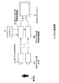
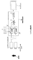
即ち、実際の撮像状況と撮像映像との関係の例を図10に示すと、図10(a)に上側から示すように、基準面cの手前にいる被写体aと、その基準面cの後ろ側から前側に位置が順に変化するように並んだ建造物b1,b2,・・・,b9があるとする。このような状態をカメラ装置1で撮像すると、撮像して得られた映像は、図10(b)に示す状態となり、被写体aと建造物b1〜b9とが並んでいる。ここで、建造物b1〜b9は、基準面cとの位置関係が異なり、例えば立体視用の撮像を行ったときには、左チャンネル映像と右チャンネル映像とで、位置が変化しているが、図10のように各チャンネルの映像を個別にみた場合には、ほとんど変化がない。従って、立体表示用でない通常のディスプレイで各チャンネルの映像を個別に表示させたのでは、立体視できる効果などは簡単には判らない問題がある。 That is, FIG. 10 shows an example of the relationship between the actual imaging situation and the captured image. As shown from the upper side in FIG. 10A, the subject a in front of the reference plane c and the back of the reference plane c. Assume that there are buildings b1, b2,..., B9 arranged in such a manner that their positions change in order from the side to the front side. When such a state is imaged by the camera device 1, the image obtained by imaging is in the state shown in FIG. 10B, and the subject a and the buildings b1 to b9 are arranged side by side. Here, the positions of the buildings b1 to b9 are different from those of the reference plane c. For example, when stereoscopic imaging is performed, the positions of the left channel image and the right channel image change. When the video of each channel is viewed individually as in FIG. 10, there is almost no change. Accordingly, there is a problem that the effect of being able to view stereoscopically cannot be easily understood if the images of each channel are individually displayed on a normal display that is not for stereoscopic display.
また、これらの映像信号を表示させて立体視させるためには、左右のチャンネルの映像信号が正確に同期している必要があり、左右で表示位置についても、ずれがないことが重要である。しかしながら、そのような確認も、立体表示用でない通常のディスプレイでは簡単には判らない。 In addition, in order to display these video signals for stereoscopic viewing, the video signals of the left and right channels need to be accurately synchronized, and it is important that the display positions on the left and right are not shifted. However, such confirmation is not easily understood with a normal display that is not for stereoscopic display.
本発明はこれらの点に鑑みてなされたものであり、通常の表示装置を使って、立体表示用の映像の確認が良好にできるようにすることを目的とする。 The present invention has been made in view of these points, and an object of the present invention is to make it possible to satisfactorily confirm a stereoscopic display image using a normal display device.
本発明は、色変換処理部を備えた構成とする。色変換処理部は、左チャンネル用映像信号と右チャンネル用映像信号との少なくともいずれか一方のチャンネルの映像信号を特定の色の単色の映像の映像信号とするものである。また、合成される少なくともいずれか一方のチャンネル用映像信号は、立体効果状態を計るための目盛りの映像を重畳させた映像信号であり、さらに、左チャンネル用映像信号に左チャンネルであることを示す映像を重畳させると共に、右チャンネル用映像信号に右チャンネルであることを示す映像を重畳させる処理を行う。 The present invention is configured to include a color conversion processing unit. The color conversion processing unit converts the video signal of at least one of the left channel video signal and the right channel video signal into a single color video signal of a specific color. Further, at least one of the channel video signals to be synthesized is a video signal in which a scale image for measuring the stereoscopic effect state is superimposed, and further indicates that the left channel video signal is the left channel. A process of superimposing the video and superimposing the video indicating the right channel on the video signal for the right channel is performed.
このようにしたことで、その特定の色の単色による一方のチャンネルの映像を、他方のチャンネルの映像に重ねて表示させることで、左右のチャンネルで映像に変化がある個所については、その特定の色の部分の表示状況から判るようになる。また、左右のチャンネルの映像の表示タイミングや表示位置などが同期しているのかも、容易に判るようになる。 In this way, by displaying the video of one channel in a single color with the specific color superimposed on the video of the other channel, the location where the video changes in the left and right channels It can be seen from the display status of the color part. In addition, it can be easily understood whether the display timings and display positions of the left and right channel images are synchronized.
本発明によると、立体表示を行うための映像の確認が、色変換処理を行った色の部分の状況の表示状態の確認から、簡単に行えるようになる効果を有する。 According to the present invention, there is an effect that confirmation of an image for performing stereoscopic display can be easily performed from confirmation of a display state of a state of a color portion subjected to color conversion processing.
本発明の実施の形態を、以下の順序で説明する。
・一実施の形態のシステム構成例(図1)
・一実施の形態の映像処理装置の構成例(図2)
・各表示モードの処理の説明(図3〜図7)
・他の実施の形態によるシステム構成例(図8、図9)
Embodiments of the present invention will be described in the following order.
-System configuration example of one embodiment (FIG. 1)
A configuration example of the video processing apparatus according to the embodiment (FIG. 2)
・ Description of processing in each display mode (FIGS. 3 to 7)
-System configuration examples according to other embodiments (FIGS. 8 and 9)
[一実施の形態のシステム構成例]
以下、図1を参照して、本実施の形態のシステム構成例について説明する。
本実施の形態においては、立体視を行う映像信号である、左チャンネル用映像信号と右チャンネル用映像信号との供給を受けて、処理するシステムとしてある。即ち、被写体aを、左チャンネル用カメラ装置1Lと右チャンネル用カメラ装置1Rとで撮像して、左チャンネル用映像信号と右チャンネル用映像信号と3D表示用映像信号を出力させる構成としてある。
[System configuration example of one embodiment]
Hereinafter, a system configuration example of the present embodiment will be described with reference to FIG.
The present embodiment is a system that receives and processes a left-channel video signal and a right-channel video signal, which are stereoscopic video signals. That is, the subject a is imaged by the left
左チャンネル用カメラ装置1Lが出力する左チャンネル用映像信号は、左チャンネル用映像処理装置2Lに供給する。右チャンネル用カメラ装置1Rが出力する右チャンネル用映像信号は、右チャンネル用映像処理装置2Rに供給する。左チャンネル用映像処理装置2Lと右チャンネル用映像処理装置2Rは、コントローラ4からの指示で、供給される映像信号の処理を行う。コントローラ4は、ユーザの操作に基づいて、表示モードの指示を行う制御部である。表示モードの詳細例については後述する。
なお、左チャンネル用映像処理装置2Lと右チャンネル用映像処理装置2Rは、図1では別体の装置として構成してあるが、一体に構成してもよい。また、コントローラ4についても、映像処理装置と一体に構成してもよい。
The left channel video signal output from the left
Note that the left channel
左チャンネル用映像処理装置2Lと右チャンネル用映像処理装置2Rは、コントローラ4からの指示に基づいて、入力した映像信号の処理を行い、処理された映像信号を出力する。コントローラ4から指示されたモードによっては、何も処理しないで、出力させる場合もある。各映像処理装置2L,2Rの詳細構成例については後述する。
The left-channel
左チャンネル用映像処理装置2Lと右チャンネル用映像処理装置2Rが出力する映像信号は、ディスプレイ3に供給し、ディスプレイ3で入力した映像信号による映像を表示させる。
ディスプレイ3は、立体視が可能な表示装置である3D対応ディスプレイである。即ち、入力した左チャンネル用映像信号と右チャンネル用映像信号とを同時に表示処理して、フレームごとやラインごとに2つのチャンネルの映像を1つの画面上に交互に表示させる。
The video signals output from the left-channel
The
[一実施の形態の映像処理装置の構成例]
次に、図2を参照して、チャンネル用映像処理装置2Lと右チャンネル用映像処理装置2Rの構成例を説明する。
チャンネル用映像処理装置2Lと右チャンネル用映像処理装置2Rは、基本的に同一構成であり、図2では1組の映像処理装置の構成だけを示してある。
図2に従って説明すると、入力端子11に得られる映像信号を、第1の変換回路12に供給する。第1の変換回路12は、輝度信号と色差信号とで構成される映像信号Y,CB,CRを、原色信号で構成される映像信号R,G,Bに変換する。第1の変換回路12では、マトリクス回路にて、次の数1式による変換が行われる。
[Configuration Example of Video Processing Apparatus According to One Embodiment]
Next, a configuration example of the channel
The channel
Referring to FIG. 2, the video signal obtained at the

第1の変換回路12で変換された映像信号R,G,Bは、信号選択回路13に供給する。信号選択回路13では、映像信号R,G,Bから、強調させる色のみを取り出す処理が行われる。信号選択回路13では、マトリクス回路にて、次の数2式による変換で強調処理が行われる。
The video signals R, G, and B converted by the
信号選択回路13で選択処理が行われた映像信号は、第2の変換回路14に供給する。第2の変換回路14では、原色信号で構成される映像信号R,G,Bを、輝度信号と色差信号とで構成される映像信号Y,CB,CRに再変換する。第2の変換回路14では、マトリクス回路にて、次の数3式による変換が行われる。
The video signal that has been selected by the signal selection circuit 13 is supplied to the
第2の変換回路14で変換された映像信号Y,CB,CRは、信号選択回路15に供給する。信号選択回路15では、指示に基づいて映像信号Y,CB,CRの色変換処理を行う。ここでは、モノクロ信号(白黒信号)に変換する処理、又は、特定の色の単色の映像信号に変換する処理が、選択的に実行される。信号選択回路15では、マトリクス回路にて、次の数4式による変換処理が行われる。
The video signals Y, CB, CR converted by the
信号選択回路15で特定の色の単色の映像信号に変換する処理としては、原色信号系の色を扱う場合には、赤色成分だけの映像信号に変換する処理、緑色成分だけの映像信号に変換する処理、青色成分だけの映像信号に変換する処理がある。また、補色信号系の色を扱う場合には、黄色成分だけの映像信号に変換する処理、シアン色成分だけの映像信号に変換する処理、マゼンタ色色成分だけの映像信号に変換する処理がある。
The
信号選択回路15で選択処理が行われた映像信号は、固定レベル挿入回路16に供給する。固定レベル挿入回路16は、各フレームの映像中の指示された位置に、固定レベルの映像(文字,図形など)を選択的に挿入する回路である。挿入する映像としては、例えば、左チャンネルを示す「L」の文字、右チャンネルを示す「R」の文字、立体状況を示すスケール(メモリ)の図形などがある。
固定レベル挿入回路16で映像を挿入する位置は、同期分離回路21で入力映像信号から分離した水平タイミング信号及び垂直タイミング信号に基づいて設定される。即ち、同期分離回路21で得られた垂直タイミング信号をラインカウンタ22に供給して、水平ラインの位置を示すラインカウンタ値を得て、そのラインカウンタ値を固定レベル挿入回路16に供給する。また、同期分離回路21で得られた水平タイミング信号をドットカウンタ23に供給して、水平ライン中の画素位置(ドット位置)を示すドットカウンタ値を得て、そのドットカウンタ値を固定レベル挿入回路16に供給する。固定レベル挿入回路16では、これらのカウンタ値から、映像の挿入位置を判断する。
The video signal subjected to the selection process by the
The position where the video is inserted by the fixed
固定レベル挿入回路16で処理が行われた映像信号は、切換スイッチ17に供給する。切換スイッチ17は、固定レベル挿入回路16が出力する映像信号と、入力端子11に得られる映像信号とを選択するスイッチであり、選択された映像信号を出力端子18から出力させる。
The video signal processed by the fixed
この映像処理装置2L,2Rは、制御手段であるCPU20で、各回路12〜16や切換スイッチ17での処理が制御される構成としてあり、外部のコントローラ4から指示された表示モードに応じた制御を行う。コントローラ4は、ユーザが表示モードなどを設定する操作部5を備え、その操作部5で入力されたモードなどに応じて、CPU20に指示を行う。
The
[各表示モードの処理の説明]
次に、映像処理装置2L,2Rで処理を行う表示モードについて説明する。
図3は、本実施の形態の例でのモードの一覧と、各モードでの、左チャンネル映像信号及び右チャンネル映像信号の処理を示したものである。
用意された表示モードとしては、左チャンネル強調モード、右チャンネル強調モード、左右強調モードとがある。左チャンネル強調モードと右チャンネル強調モードについては、逆チャンネルをモノクロとするモードも用意してある。
[Description of processing in each display mode]
Next, a display mode in which processing is performed by the
FIG. 3 shows a list of modes in the example of the present embodiment and processing of the left channel video signal and the right channel video signal in each mode.
The prepared display modes include a left channel enhancement mode, a right channel enhancement mode, and a left / right enhancement mode. For the left channel enhancement mode and the right channel enhancement mode, a mode in which the reverse channel is monochrome is also prepared.
左チャンネル強調モードの場合は、左チャンネル映像信号として、第1の単色の映像信号として出力させ、右チャンネル映像信号を、入力されたままのカラー映像信号として出力させる。第1の単色としては、例えば赤色とする。
左チャンネル強調モードで、逆チャンネルをモノクロとする場合には、左チャンネル映像信号として、第1の単色の映像信号として出力させ、右チャンネル映像信号を、モノクロ映像信号として出力させる。
In the case of the left channel enhancement mode, the first channel video signal is output as a left channel video signal, and the right channel video signal is output as a color video signal as it is input. For example, the first single color is red.
When the reverse channel is set to monochrome in the left channel enhancement mode, the first channel video signal is output as the left channel video signal and the right channel video signal is output as the monochrome video signal.
右チャンネル強調モードの場合は、右チャンネル映像信号として、第2の単色の映像信号として出力させ、左チャンネル映像信号を、入力されたままのカラー映像信号として出力させる。第2の単色としては、例えば青色とする。
右チャンネル強調モードで、逆チャンネルをモノクロとする場合には、右チャンネル映像信号として、第2の単色の映像信号として出力させ、左チャンネル映像信号を、モノクロ映像信号として出力させる。
In the right channel emphasis mode, the second channel video signal is output as the right channel video signal, and the left channel video signal is output as the input color video signal. The second single color is, for example, blue.
When the reverse channel is set to monochrome in the right channel emphasis mode, the second channel video signal is output as the right channel video signal and the left channel video signal is output as the monochrome video signal.
左右強調モードの場合は、左チャンネル映像信号として、第1の単色の映像信号として出力させ、右チャンネル映像信号として、第2の単色の映像信号として出力させる。
なお、それぞれのモードで設定する色は、ユーザ操作で自由に変更することができる。
In the left-right emphasis mode, the first channel video signal is output as the first monochromatic video signal, and the second channel video signal is output as the second monochromatic video signal.
The color set in each mode can be freely changed by a user operation.
次に、このようにモード設定して左チャンネル用映像処理装置2Lと右チャンネル用映像処理装置2Rとで処理を行った映像信号を、ディスプレイ3に表示させた場合の例を、図4〜図7に示す。
Next, an example in which the video signal processed by the left channel
図4は、左チャンネル強調モードでの撮像状態と表示例を示した図である。
図4(a)に上側から示すように、基準面cの手前にいる被写体aと、その基準面cの後ろ側から前側に位置が順に変化するように並んだ建造物b1,b2,・・・,b9がある状態を、左右のチャンネル用カメラ装置1L,1Rで撮像したとする。この撮像される映像は、図10での撮像状態と同じである。
そして、その撮像して得られたそれぞれのチャンネルの映像信号を、左チャンネル用映像処理装置2Lと右チャンネル用映像処理装置2Rとで処理を行って、ディスプレイ3で、左右のチャンネルの映像を同時(又は交互)に表示させたとする。図4(b)は、この表示映像を示したものである。
FIG. 4 is a diagram illustrating an imaging state and a display example in the left channel enhancement mode.
As shown from the upper side in FIG. 4A, the subject a in front of the reference plane c and the buildings b1, b2,... Arranged in such a manner that their positions change in order from the rear side to the front side of the reference plane c. Suppose that b9 is captured by the left and right
The video signals of the respective channels obtained by imaging are processed by the left channel
図4(b)に示すように、この左チャンネル強調モードでは、左チャンネル用カメラ装置1Lで撮像した左チャンネルの映像信号だけを、単色としてあり、その単色の部分を、ハッチング(斜線)を付与した範囲で示してある。なお、右チャンネルの建造物b1〜b9や被写体aが表示される位置については、左チャンネルと区別するために、一定間隔の点を付与した範囲で示してある。
各建造物b1〜b9は、基準面cからの位置が異なるため、斜線を付与した、一方のチャンネルの範囲と、通常の色(映像信号で示されるそのままの色)で表示される他方のチャンネルの範囲との重なり状態が、順に変化している。即ち、一番奥の建造物b1については、左チャンネルの映像が右側に出た状態で重なり、基準面cと同じ位置の建造物b5については、左右のチャンネルの映像が一致し、一番手前の建造物b9については、左チャンネルの映像が左側に出た状態で重なっている。
また、この例では、左右のチャンネルを示す文字である「L」の表示S1と、「R」の表示S2とを、画面の隅などに表示させてあり、その内の、左チャンネルを示す「L」の表示S1の文字の色を、単色にしてある。この文字の色は、左チャンネルの映像全体の色と同じとする。右チャンネルを示す「R」の表示S2については、白又は黒などで表示させてある。
As shown in FIG. 4B, in this left channel enhancement mode, only the video signal of the left channel captured by the left
Since each building b1 to b9 has a different position from the reference plane c, the range of one channel to which diagonal lines are given and the other channel displayed in a normal color (as it is shown in the video signal) The state of overlap with the range of is changing in order. That is, for the innermost building b1, the image of the left channel overlaps in a state where the image is on the right side, and for the building b5 at the same position as the reference plane c, the images of the left and right channels are the same. As for the building b9, the image of the left channel is overlapped with the image on the left side.
In this example, a display S1 of “L”, which is a character indicating the left and right channels, and a display S2 of “R” are displayed at the corners of the screen, etc. The character color of the display S1 of “L” is set to a single color. The color of this character is the same as the color of the entire left channel image. The display S2 of “R” indicating the right channel is displayed in white or black.
なお、左チャンネル強調モードで、逆チャンネルをモノクロとするモードとした場合には、図4(b)に示した表示の内の、右チャンネルの映像がモノクロ表示となり、左チャンネルが設定した単色(黒以外の色)となる。 In the left channel enhancement mode, when the reverse channel is set to the monochrome mode, the right channel image in the display shown in FIG. 4B is displayed in monochrome and the left channel is set to a single color ( Color other than black).
図4は、左チャンネル強調モードでの撮像状態と表示例を示した図である。
図4(a)に上側から示すように、基準面cの手前にいる被写体aと、その基準面cの後ろ側から前側に位置が順に変化するように並んだ建造物b1,b2,・・・,b9がある状態を、左右のチャンネル用カメラ装置1L,1Rで撮像したとする。この撮像される映像は、図10での撮像状態と同じである。
そして、その撮像して得られたそれぞれのチャンネルの映像信号を、左チャンネル用映像処理装置2Lと右チャンネル用映像処理装置2Rとで処理を行って、ディスプレイ3で、左右のチャンネルの映像を同時(又は交互)に表示させたとする。図4(b)は、この表示映像を示したものである。
FIG. 4 is a diagram illustrating an imaging state and a display example in the left channel enhancement mode.
As shown from the upper side in FIG. 4A, the subject a in front of the reference plane c and the buildings b1, b2,... Arranged in such a manner that their positions change in order from the rear side to the front side of the reference plane c. Suppose that b9 is captured by the left and right
The video signals of the respective channels obtained by imaging are processed by the left channel
図4(b)に示すように、この左チャンネル強調モードでは、左チャンネル用カメラ装置1Lで撮像した左チャンネルの映像信号だけを、単色としてあり、その単色の部分を、ハッチング(斜線)を付与した範囲で示してある。
各建造物b1〜b9は、基準面cからの位置が異なるため、斜線を付与した、一方のチャンネルの範囲と、通常の色(映像信号で示されるそのままの色)で表示される他方のチャンネルの範囲との重なり状態が、順に変化している。即ち、一番奥の建造物b1については、左チャンネルの映像が右側に出た状態で重なり、基準面cと同じ位置の建造物b5については、左右のチャンネルの映像が一致し、一番手前の建造物b9については、左チャンネルの映像が左側に出た状態で重なっている。
また、この例では、左右のチャンネルを示す文字である「L」の表示S1と、「R」の表示S2とを、画面の隅などに表示させてあり、その内の、左チャンネルを示す「L」の表示S1の文字の色を、単色にしてある。この文字の色は、左チャンネルの映像全体の色と同じとする。右チャンネルを示す「R」の表示S2については、白又は黒などで表示させてある。
As shown in FIG. 4B, in this left channel enhancement mode, only the video signal of the left channel captured by the left
Since each building b1 to b9 has a different position from the reference plane c, the range of one channel to which diagonal lines are given and the other channel displayed in a normal color (as it is shown in the video signal) The state of overlap with the range of is changing in order. That is, for the innermost building b1, the image of the left channel overlaps in a state where the image is on the right side, and for the building b5 at the same position as the reference plane c, the images of the left and right channels are the same. As for the building b9, the image of the left channel is overlapped with the image on the left side.
In this example, a display S1 of “L”, which is a character indicating the left and right channels, and a display S2 of “R” are displayed at the corners of the screen, etc. The character color of the display S1 of “L” is set to a single color. The color of this character is the same as the color of the entire left channel image. The display S2 of “R” indicating the right channel is displayed in white or black.
なお、左チャンネル強調モードで、逆チャンネルをモノクロとするモードとした場合には、図4(b)に示した表示の内の、右チャンネルの映像がモノクロ表示となり、左チャンネルが設定した単色(黒以外の色)となる。 In the left channel enhancement mode, when the reverse channel is set to the monochrome mode, the right channel image in the display shown in FIG. 4B is displayed in monochrome and the left channel is set to a single color ( Color other than black).
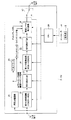
図5は、右チャンネル強調モードでの撮像状態と表示例を示した図である。
図5(a)は撮像状態を上から見た図であり、図4での撮像状態と同じである。このように撮像して得られたそれぞれのチャンネルの映像信号を、左チャンネル用映像処理装置2Lと右チャンネル用映像処理装置2Rとで処理を行って、ディスプレイ3で、左右のチャンネルの映像を同時(又は交互)に表示させたとする。図5(b)は、この表示映像を示したものである。
FIG. 5 is a diagram illustrating an imaging state and a display example in the right channel enhancement mode.
FIG. 5A is a diagram of the imaging state viewed from above, and is the same as the imaging state in FIG. The video signals of the respective channels obtained by imaging in this way are processed by the left channel
図5(b)に示すように、この右チャンネル強調モードでは、右チャンネル用カメラ装置1Rで撮像した右チャンネルの映像信号だけを、単色としてあり、その単色の部分を、ハッチング(斜線)を付与した範囲で示してある。なお、左チャンネルの建造物b1〜b9や被写体aが表示される位置については、右チャンネルと区別するために、一定間隔の点を付与した範囲で示してある。
各建造物b1〜b9は、基準面cからの位置が異なるため、斜線を付与した、一方のチャンネルの範囲と、通常の色(映像信号で示されるそのままの色)で表示される他方のチャンネルの範囲との重なり状態が、順に変化している。即ち、一番奥の建造物b1については、右チャンネルの映像が左側に出た状態で重なり、基準面cと同じ位置の建造物b5については、左右のチャンネルの映像が一致し、一番手前の建造物b9については、右チャンネルの映像が右側に出た状態で重なっている。
また、この例では、左右のチャンネルを示す文字である「L」の表示S1と、「R」の表示S2とを、画面の隅などに表示させてあり、その内の、右チャンネルを示す「R」の表示S2の文字の色を、単色にしてある。この文字の色は、右チャンネルの映像全体の色と同じとする。左チャンネルを示す「L」の表示S1については、白又は黒などで表示させてある。
As shown in FIG. 5B, in this right channel emphasis mode, only the video signal of the right channel imaged by the right
Since each building b1 to b9 has a different position from the reference plane c, the range of one channel to which diagonal lines are given and the other channel displayed in a normal color (as it is shown in the video signal) The state of overlap with the range of is changing in order. That is, the image of the right channel is overlapped in the state where the image of the right channel comes out on the left side for the building b1, and the image of the left and right channels is the same for the building b5 at the same position as the reference plane c. For the building b9, the video of the right channel overlaps with the right side protruding.
In this example, a display S1 of “L”, which is a character indicating the left and right channels, and a display S2 of “R” are displayed at the corners of the screen and the like. The character color of the display S2 of “R” is a single color. The color of this character is the same as the color of the entire image of the right channel. The display S1 of “L” indicating the left channel is displayed in white or black.
なお、左チャンネル強調モードで、逆チャンネルをモノクロとするモードとした場合には、図5(b)に示した表示の内の、左チャンネルの映像がモノクロ表示となり、右チャンネルが設定した単色(黒以外の色)となる。 In the left channel emphasis mode, when the reverse channel is set to the monochrome mode, the left channel image in the display shown in FIG. 5B is displayed in monochrome, and the right channel is set to a single color ( Color other than black).
図6は、左右チャンネル強調モードでの撮像状態と表示例を示した図である。
図6(a)は撮像状態を上から見た図であり、図4,図5での撮像状態と同じである。このように撮像して得られたそれぞれのチャンネルの映像信号を、左チャンネル用映像処理装置2Lと右チャンネル用映像処理装置2Rとで処理を行って、ディスプレイ3で、左右のチャンネルの映像を同時(又は交互)に表示させたとする。図6(b)は、この表示映像を示したものである。
FIG. 6 is a diagram illustrating an imaging state and a display example in the left and right channel enhancement mode.
FIG. 6A is a diagram of the imaging state viewed from above, and is the same as the imaging state in FIGS. 4 and 5. The video signals of the respective channels obtained by imaging in this way are processed by the left channel
図6(b)に示すように、この左右チャンネル強調モードでは、左チャンネル用カメラ装置1Lで撮像した左チャンネルの映像を、第1の色(赤など)の単色映像とし、右チャンネル用カメラ装置1Rで撮像した右チャンネルの映像を、第2の色(青など)の単色映像としてある。それぞれの単色の部分を、向きが異なるハッチング(斜線)を付与した範囲で示してある。
この図6(b)から判るように、一方のチャンネルの範囲と、他方のチャンネルの範囲との重なり状態が、順に変化しており、その変化状態が容易に判るようになっている。
この例では、左右のチャンネルを示す文字である「L」の表示S1と、「R」の表示S2とを、画面の隅などに表示させてあり、その内の、左チャンネルを示す「L」の表示S1の文字の色を、第1の色にしてある。右チャンネルを示す「R」の表示S2の文字の色は、第2の色にしてある。
As shown in FIG. 6B, in this left and right channel emphasis mode, the left channel image captured by the left
As can be seen from FIG. 6B, the overlapping state of the range of one channel and the range of the other channel changes in order, and the changing state can be easily understood.
In this example, a display S1 of “L”, which is a character indicating the left and right channels, and a display S2 of “R” are displayed at the corners of the screen, and among these, “L” indicating the left channel. The character color of the display S1 is set to the first color. The character color of the display S2 of “R” indicating the right channel is the second color.
このように表示させることで、2つのチャンネルの映像の違いが、1つの画面上の表示から明確に判るようになる。また、2つのチャンネルの映像の同期状態や、表示位置のずれなども、表示から簡単に判るようになる。 By displaying in this way, the difference between the images of the two channels can be clearly seen from the display on one screen. In addition, the synchronization state of the images of the two channels, the display position shift, and the like can be easily understood from the display.
なお、それぞれの表示モードにおいて、チャンネル用映像処理装置2Lと右チャンネル用映像処理装置2Rとの処理で、映像中にスケール(目盛り)を同時に表示させることを可能としてある。
図7は、このスケールS3の表示例を示したものである。図7に示すように、水平方向に伸びて、一定間隔で目盛りが入ったスケールとしてあり、そのスケールを参照することで、表示映像の左右のずれが、基準面からのどの程度の距離に相当するのかが判るようになる。なお、スケールの目盛りには、数値を同時に表示させるようにしてもよい。
In each display mode, it is possible to simultaneously display scales (scales) in the video by the processing of the channel
FIG. 7 shows a display example of the scale S3. As shown in FIG. 7, the scale extends in the horizontal direction and has scales at regular intervals. By referring to the scale, the horizontal shift of the display image corresponds to the distance from the reference plane. You will know what to do. Note that numerical values may be displayed simultaneously on the scale.
[他の実施の形態によるシステム構成例]
図1に示したシステム構成では、左チャンネル用映像処理装置2Lと右チャンネル用映像処理装置2Rとを別体で構成したが、一体の映像処理装置として構成させてもよい。
図8は、この場合の構成例を示した図である。
図8において、映像処理装置30は、図2に示した左チャンネル用映像処理装置2Lでの処理と、図2に示した右チャンネル用映像処理装置2Rでの処理を実行する処理装置である。即ち、図8に示した左チャンネル用映像処理部2L′は、左チャンネル用映像処理装置2Lと同様の処理回路を備えた処理部であり、右チャンネル用映像処理部2R′は、右チャンネル用映像処理装置2Rと同様の処理回路を備えた処理部である。各映像処理部2L′,2R′は、各チャンネル用カメラ1L,1Rからの映像信号を処理する。各映像処理部2L′,2R′は、コントローラ4からの指示で処理モード(表示モード)が設定される。
[System configuration example according to another embodiment]
In the system configuration shown in FIG. 1, the left-channel
FIG. 8 is a diagram showing a configuration example in this case.
In FIG. 8, the
そして、映像処理装置30内で、左チャンネル用映像処理部2L′が出力する映像信号と、右チャンネル用映像処理部2R′が出力する映像信号とを合成部5に供給して、1系統の映像信号に合成する。合成した映像信号は、出力部6から出力させて、ディスプレイ7に供給する。ディスプレイ7は、3D表示を行うためのディスプレイである必要はない。
Then, in the
このように構成することで、立体表示用でない通常の表示装置で、図4〜図7に示した各モードの表示が可能になる。 With this configuration, it is possible to display each mode shown in FIGS. 4 to 7 with a normal display device that is not for stereoscopic display.
図9は、表示装置に内蔵させた例である。
図9に示したディスプレイ40は、入力端子41に得られる左チャンネル用映像信号を、左チャンネル用映像処理部2L′に供給し、入力端子42に得られる右チャンネル用映像信号を、右チャンネル用映像処理部2R′に供給する。各映像処理部2L′,2R′は、図8の例と同様に、図2に示した映像処理装置2L,2Rと同様の構成であり、ディスプレイのコントローラ43により制御される。コントローラ43が、図3に示した各表示モードの設定を指示する。
FIG. 9 shows an example in which the display device is incorporated.
The display 40 shown in FIG. 9 supplies the left channel video signal obtained at the
そして、左チャンネル用映像処理部2L′が出力する映像信号と、右チャンネル用映像処理部2R′が出力する映像信号とを合成部44に供給して、1系統の映像信号に合成し、その合成された映像信号を表示処理部45に供給する。表示処理部45は、表示パネル46を駆動する処理を行い、映像を表示させる。
Then, the video signal output from the left channel
このように、表示装置内で全ての処理を行う構成として、図4〜図7に示した各モードの表示が可能になる。 As described above, the display in each mode shown in FIGS. 4 to 7 can be performed as a configuration in which all processes are performed in the display device.
また、これらの各図に示した構成のように、映像信号処理を行う専用の回路を構成させるのではなく、例えば各種データ処理を行うパーソナルコンピュータ装置に、本例の映像処理部に相当する映像処理(画像処理)を行うボードやカードなどを装着させる。そして、そのコンピュータ装置に実装させて、演算処理手段で実行するプログラム(ソフトウェア)で、対応した表示処理を行うようにしてもよい。 In addition, as in the configuration shown in each of these drawings, a dedicated circuit for performing video signal processing is not configured, but a video corresponding to the video processing unit of this example is provided in a personal computer device that performs various data processing, for example. A board or card for processing (image processing) is mounted. Then, the display processing may be performed by a program (software) that is installed in the computer device and executed by the arithmetic processing means.
1…カメラ装置、1L…左チャンネル用カメラ装置、1R…右チャンネル用カメラ装置、2L…左チャンネル用映像処理装置、2L′…左チャンネル用映像処理部、2R…右チャンネル用映像処理装置、2R′…右チャンネル用映像処理部、3…3D対応ディスプレイ、4…コントローラ、5…合成部、6…出力部、7…ディスプレイ、11…入力端子、12…第1の変換回路、13…信号選択回路、14…第2の変換回路、15…信号選択回路、16…固定レベル挿入回路、17…切換スイッチ、18…出力端子、20…CPU、21…同期分離回路、22…ラインカウンタ、23…ドットカウンタ、30…映像処理装置、40…ディスプレイ、41,42…入力端子、43…コントローラ、44…合成部、45…表示処理部、46…表示パネル DESCRIPTION OF SYMBOLS 1 ... Camera device, 1L ... Camera device for left channel, 1R ... Camera device for right channel, 2L ... Video processing device for left channel, 2L '... Video processing unit for left channel, 2R ... Video processing device for right channel, 2R '... Right channel video processing unit, 3 ... 3D compatible display, 4 ... controller, 5 ... compositing unit, 6 ... output unit, 7 ... display, 11 ... input terminal, 12 ... first conversion circuit, 13 ... signal selection Circuit, 14 ... 2nd conversion circuit, 15 ... Signal selection circuit, 16 ... Fixed level insertion circuit, 17 ... Changeover switch, 18 ... Output terminal, 20 ... CPU, 21 ... Synchronous separation circuit, 22 ... Line counter, 23 ... Dot counter, 30 ... Video processing device, 40 ... Display, 41, 42 ... Input terminal, 43 ... Controller, 44 ... Composition unit, 45 ... Display processing unit, 46 ... Display Nel
Claims (6)
前記入力部に入力した左チャンネル用映像信号と右チャンネル用映像信号との少なくとも何れか一方のチャンネルの映像信号を、特定の色の単色の映像の映像信号とする色変換処理部と、
前記色変換処理部で変換された映像信号を含む映像信号を出力する出力部とを備え、
前記出力部から出力される少なくともいずれか一方のチャンネル用映像信号は、立体効果状態を計るための目盛りの映像を重畳させた映像信号であり、
さらに、左チャンネル用映像信号に左チャンネルであることを示す映像を重畳させると共に、右チャンネル用映像信号に右チャンネルであることを示す映像を重畳させる、
映像処理装置。 An input unit for inputting a video signal for at least one of the video signal for the left channel and the video signal for the right channel;
A color conversion processing unit that converts the video signal of at least one of the left channel video signal and the right channel video signal input to the input unit into a single color video signal of a specific color;
Bei example an output section for outputting a video signal including the converted video signal by the color conversion processing unit,
The video signal for at least one of the channels output from the output unit is a video signal in which an image of a scale for measuring the stereoscopic effect state is superimposed,
Furthermore, a video indicating that the channel is the left channel is superimposed on the video signal for the left channel, and a video indicating that the channel is the right channel is superimposed on the video signal for the right channel.
Video processing device.
請求項1記載の映像処理装置。 The video processing apparatus according to claim 1, wherein the color conversion processing unit uses a channel video signal different from the channel video signal as the monochrome video signal of the specific color as a monochrome video signal.
請求項1記載の映像処理装置。 The color conversion processing unit converts a channel video signal different from the channel video signal, which is a single color video signal of the specific color, to a single color video of a specific color different from the specific color. The video processing apparatus according to claim 1, wherein the video signal is a video signal.
前記入力部に入力した左チャンネル用映像信号と右チャンネル用映像信号との少なくとも何れか一方のチャンネルの映像信号を特定の色の単色の映像の映像信号とする色変換処理部と、
前記色変換処理部で変換された映像信号を含む左右のチャンネル用映像信号を合成する合成部と、
前記合成部で構成されたチャンネル用映像信号による映像を表示する表示部とを備え、
前記合成部で合成される少なくともいずれか一方のチャンネル用映像信号は、立体効果状態を計るための目盛りの映像を重畳させた映像信号であり、
さらに、左チャンネル用映像信号に左チャンネルであることを示す映像を重畳させて前記表示部に表示させると共に、右チャンネル用映像信号に右チャンネルであることを示す映像を重畳させて前記表示部に表示させる、
表示装置。 An input unit for inputting a left channel video signal and a right channel video signal;
A color conversion processing unit that uses a video signal of at least one of the left channel video signal and the right channel video signal input to the input unit as a video signal of a single color video of a specific color;
A combining unit that combines the left and right channel video signals including the video signal converted by the color conversion processing unit;
Bei example a display unit for displaying an image by channel video signal composed by the composition unit,
The video signal for at least one of the channels synthesized by the synthesis unit is a video signal in which an image of a scale for measuring the stereoscopic effect state is superimposed,
Furthermore, a video indicating that it is the left channel is superimposed on the video signal for the left channel and displayed on the display unit, and a video indicating that the channel is the right channel is superimposed on the video signal for the right channel and the display unit is displayed. Display,
Display device.
左チャンネル用映像信号と右チャンネル用映像信号の内の、前記色変換処理が行われた一方のチャンネル用映像信号と、他方のチャンネル用映像信号とを合成して、1つの画面として表示させる表示方法であり、
合成される少なくともいずれか一方のチャンネル用映像信号は、立体効果状態を計るための目盛りの映像を重畳させた映像信号であり、
さらに、左チャンネル用映像信号に左チャンネルであることを示す映像を重畳させて表示させると共に、右チャンネル用映像信号に右チャンネルであることを示す映像を重畳させて表示させる処理を行う
表示方法。 A color conversion process is performed in which at least one of the left channel video signal and the right channel video signal is converted into a single color video signal of a specific color,
Of the video signal and right-channel video signal for the left channel, while the channel video signal to the color conversion processing is performed, by combining the video signal for the other channel, to be displayed as a single screen Display method,
The video signal for at least one of the synthesized channels is a video signal on which a scale image for measuring the stereoscopic effect state is superimposed,
Furthermore, a display method for performing processing of superimposing and displaying a video indicating the left channel on the video signal for the left channel and displaying a video indicating the right channel on the video signal for the right channel .
左チャンネル用映像信号と右チャンネル用映像信号の内の、前記色変換処理が行われた一方のチャンネル用映像信号と、他方のチャンネル用映像信号とを合成して、1つの画面として表示させる表示処理と、
合成される少なくともいずれか一方のチャンネル用映像信号に、立体効果状態を計るための目盛りの映像を重畳させる処理と、
左チャンネル用映像信号に左チャンネルであることを示す映像を重畳させて表示させると共に、右チャンネル用映像信号に右チャンネルであることを示す映像を重畳させて表示させる処理とを、
情報処理装置に実装して実行させるプログラム。 A color conversion process in which at least one of the left channel video signal and the right channel video signal is a single color video signal of a specific color;
Of the video signal and right-channel video signal for the left channel, while the channel video signal to the color conversion processing is performed, by combining the video signal for the other channel, to be displayed as a single screen Display processing ,
A process of superimposing a scale image for measuring the stereoscopic effect state on at least one of the channel video signals to be combined;
A process of superimposing and displaying a video indicating the left channel on the video signal for the left channel and displaying a video indicating the right channel on the video signal for the right channel.
A program that is implemented and executed on an information processing device .
Priority Applications (3)
| Application Number | Priority Date | Filing Date | Title |
|---|---|---|---|
| JP2010088958A JP5477129B2 (en) | 2010-04-07 | 2010-04-07 | Video signal processing device, display device, display method, and program |
| US13/065,758 US20110249017A1 (en) | 2010-04-07 | 2011-03-29 | Image signal processing device, display device, display method and program product |
| CN2011100820825A CN102215412A (en) | 2010-04-07 | 2011-03-31 | Image signal processing device, display device, display method and program product |
Applications Claiming Priority (1)
| Application Number | Priority Date | Filing Date | Title |
|---|---|---|---|
| JP2010088958A JP5477129B2 (en) | 2010-04-07 | 2010-04-07 | Video signal processing device, display device, display method, and program |
Publications (2)
| Publication Number | Publication Date |
|---|---|
| JP2011223215A JP2011223215A (en) | 2011-11-04 |
| JP5477129B2 true JP5477129B2 (en) | 2014-04-23 |
Family
ID=44746503
Family Applications (1)
| Application Number | Title | Priority Date | Filing Date |
|---|---|---|---|
| JP2010088958A Expired - Fee Related JP5477129B2 (en) | 2010-04-07 | 2010-04-07 | Video signal processing device, display device, display method, and program |
Country Status (3)
| Country | Link |
|---|---|
| US (1) | US20110249017A1 (en) |
| JP (1) | JP5477129B2 (en) |
| CN (1) | CN102215412A (en) |
Families Citing this family (1)
| Publication number | Priority date | Publication date | Assignee | Title |
|---|---|---|---|---|
| WO2019155760A1 (en) | 2018-02-07 | 2019-08-15 | ソニー株式会社 | Image processing device, display device, and image processing method |
Family Cites Families (19)
| Publication number | Priority date | Publication date | Assignee | Title |
|---|---|---|---|---|
| JPS62213395A (en) * | 1986-03-13 | 1987-09-19 | Sony Corp | Anaglyph display device for stereoscopic image |
| JPH0666972B2 (en) * | 1987-01-19 | 1994-08-24 | 日本放送協会 | Stereoscopic color television |
| US5075766A (en) * | 1990-04-30 | 1991-12-24 | Sendelweck Gene K | Television on-screen character display system with provisions for edging characters |
| GB9109613D0 (en) * | 1991-05-03 | 1991-06-26 | Thomson Consumer Electronics | A television system having an ultrablack video signal blanking level for an on-screen character display |
| EP0631439B1 (en) * | 1993-05-21 | 1999-08-04 | Hitachi, Ltd. | Character display circuit and method for superimposing character code during blanking period of video signal |
| JPH11190987A (en) * | 1997-10-20 | 1999-07-13 | Sony Corp | Display device, marker signal configuration method, marker signal detection circuit, and control signal generation circuit |
| JP3667620B2 (en) * | 2000-10-16 | 2005-07-06 | 株式会社アイ・オー・データ機器 | Stereo image capturing adapter, stereo image capturing camera, and stereo image processing apparatus |
| JP2004145832A (en) * | 2002-08-29 | 2004-05-20 | Sharp Corp | Content creation device, content editing device, content playback device, content creation method, content editing method, content playback method, content creation program, content editing program, and mobile communication terminal |
| JP4165158B2 (en) * | 2002-09-06 | 2008-10-15 | ソニー株式会社 | Image processing apparatus and method, recording medium, and program |
| JP2005136726A (en) * | 2003-10-30 | 2005-05-26 | Canon Inc | Stereoscopic image display apparatus, stereoscopic image display system, stereoscopic image display method, and program |
| US20060285832A1 (en) * | 2005-06-16 | 2006-12-21 | River Past Corporation | Systems and methods for creating and recording digital three-dimensional video streams |
| KR100667810B1 (en) * | 2005-08-31 | 2007-01-11 | 삼성전자주식회사 | Device and method for adjusting depth of 3D image |
| US7665843B2 (en) * | 2007-02-21 | 2010-02-23 | Yiling Xie | Method and the associate mechanism for stored-image database-driven spectacle frame fitting services over public network |
| KR101345303B1 (en) * | 2007-03-29 | 2013-12-27 | 삼성전자주식회사 | Dynamic depth control method or apparatus in stereo-view or multiview sequence images |
| KR20080100984A (en) * | 2007-05-15 | 2008-11-21 | 삼성전자주식회사 | 3D image display method and apparatus |
| JP2010045584A (en) * | 2008-08-12 | 2010-02-25 | Sony Corp | Solid image correcting apparatus, solid image correcting method, solid image display, solid image reproducing apparatus, solid image presenting system, program, and recording medium |
| US8884948B2 (en) * | 2009-09-30 | 2014-11-11 | Disney Enterprises, Inc. | Method and system for creating depth and volume in a 2-D planar image |
| US8711204B2 (en) * | 2009-11-11 | 2014-04-29 | Disney Enterprises, Inc. | Stereoscopic editing for video production, post-production and display adaptation |
| US8350900B2 (en) * | 2009-12-15 | 2013-01-08 | Nvidia Corporation | Color anaglyph image generation to reduce eye strain and retinal rivalry upon viewing |
-
2010
- 2010-04-07 JP JP2010088958A patent/JP5477129B2/en not_active Expired - Fee Related
-
2011
- 2011-03-29 US US13/065,758 patent/US20110249017A1/en not_active Abandoned
- 2011-03-31 CN CN2011100820825A patent/CN102215412A/en active Pending
Also Published As
| Publication number | Publication date |
|---|---|
| CN102215412A (en) | 2011-10-12 |
| JP2011223215A (en) | 2011-11-04 |
| US20110249017A1 (en) | 2011-10-13 |
Similar Documents
| Publication | Publication Date | Title |
|---|---|---|
| US10728531B2 (en) | Image display system, image display apparatus, image display method, and storage medium | |
| US20100214473A1 (en) | Image display system, image display apparatus, and control method for image display apparatus | |
| US20110242282A1 (en) | Signal processing device, signal processing method, display device, and program product | |
| CN102300114B (en) | The display packing of stereoscopic display device and stereoscopic display device | |
| US8849012B2 (en) | Image processing apparatus and method and computer readable medium having a program for processing stereoscopic image | |
| KR101228916B1 (en) | Apparatus and method for displaying stereoscopic 3 dimensional image in multi vision | |
| CN102104763B (en) | Video signal processor and video signal processing method | |
| JP2004102526A (en) | Stereoscopic image display device, display processing method and processing program | |
| JP5540848B2 (en) | Video signal processing device, display device, display method, and program | |
| JP5477129B2 (en) | Video signal processing device, display device, display method, and program | |
| US20120050290A1 (en) | Three-dimensional image display apparatus and display method | |
| JPWO2006049208A1 (en) | Image composition apparatus and image composition method | |
| JP2015037282A (en) | Image processing device, image processing method, and program | |
| US8289373B2 (en) | Image processing method for multi-depth-of-field 3D-display | |
| TWI556653B (en) | Tag display method, device, computer program, and computer readable memory media | |
| EP2710581B1 (en) | System for providing private viewing of multimedia contents of a display | |
| JP5561081B2 (en) | Image display device | |
| KR100755020B1 (en) | Binocular stereo camera of YUB color system, stereoscopic image display method and stereoscopic image processing method using the camera | |
| JP6942493B2 (en) | Display device and display control method | |
| KR20060115013A (en) | Video display with dual LCD | |
| JP2013150063A (en) | Stereoscopic image photographing apparatus | |
| JP2013201470A (en) | Information processing device, information processing program, information processing system, and information processing method | |
| JP2011029902A (en) | Display device | |
| JP2013009324A (en) | Image display device | |
| JP2008054148A (en) | Image waveform display device and image waveform display method |
Legal Events
| Date | Code | Title | Description |
|---|---|---|---|
| A621 | Written request for application examination |
Free format text: JAPANESE INTERMEDIATE CODE: A621 Effective date: 20130228 |
|
| A977 | Report on retrieval |
Free format text: JAPANESE INTERMEDIATE CODE: A971007 Effective date: 20131004 |
|
| A131 | Notification of reasons for refusal |
Free format text: JAPANESE INTERMEDIATE CODE: A131 Effective date: 20131008 |
|
| A521 | Request for written amendment filed |
Free format text: JAPANESE INTERMEDIATE CODE: A523 Effective date: 20131122 |
|
| TRDD | Decision of grant or rejection written | ||
| A01 | Written decision to grant a patent or to grant a registration (utility model) |
Free format text: JAPANESE INTERMEDIATE CODE: A01 Effective date: 20140114 |
|
| A61 | First payment of annual fees (during grant procedure) |
Free format text: JAPANESE INTERMEDIATE CODE: A61 Effective date: 20140127 |
|
| LAPS | Cancellation because of no payment of annual fees |