JP5476263B2 - Car interior lighting system - Google Patents
Car interior lighting system Download PDFInfo
- Publication number
- JP5476263B2 JP5476263B2 JP2010209154A JP2010209154A JP5476263B2 JP 5476263 B2 JP5476263 B2 JP 5476263B2 JP 2010209154 A JP2010209154 A JP 2010209154A JP 2010209154 A JP2010209154 A JP 2010209154A JP 5476263 B2 JP5476263 B2 JP 5476263B2
- Authority
- JP
- Japan
- Prior art keywords
- lens
- vehicle interior
- light source
- interior lighting
- lighting device
- Prior art date
- Legal status (The legal status is an assumption and is not a legal conclusion. Google has not performed a legal analysis and makes no representation as to the accuracy of the status listed.)
- Expired - Fee Related
Links
Images


Description
本発明は、車室内を照らす車室内照明装置に関する。 The present invention relates to a vehicle interior lighting device that illuminates a vehicle interior.
車室の天井面には車室内を照らす車室内照明装置が設けられている。近年、4名以上で6名から8名が乗車することのできるワゴンタイプの車両の増加に伴い、運転席のある1列目から3列目にそれぞれ車室内照明装置を備えた車両も増加し、運転者以外の搭乗者が車室内照明装置を操作する機会が増えている。一般的に、車室内照明装置には光源をオンオフするためのプッシュスイッチやスライドスイッチなどが設けられている。しかし、これらのスイッチは、天井又は視認性が悪い場所に設置されているため夜間見つけにくく手探りによってスイッチを操作する必要あった。 A vehicle interior lighting device for illuminating the vehicle interior is provided on the ceiling surface of the vehicle interior. In recent years, with the increase in wagon type vehicles that can accommodate 6 to 8 people with more than 4 people, the number of vehicles equipped with interior lighting devices in the 1st to 3rd rows with driver seats has also increased. There are increasing opportunities for passengers other than the driver to operate the interior lighting device. Generally, a vehicle interior lighting device is provided with a push switch, a slide switch, and the like for turning on and off a light source. However, since these switches are installed on the ceiling or in a place with poor visibility, it is difficult to find them at night and it is necessary to operate the switches by groping.
そこで、操作性を改善するために車室内照明装置のレンズ面全体をプッシュスイッチの押下げ面としたものがある。しかし、レンズ面全体をプッシュスイッチの押し下げ面のように構成してもレンズ面の一端を支点にしたシーソースイッチ等が用いられていたため、レンズ面の特定の部位を押し下げる必要があり、操作性はあまり向上していなかった。 Therefore, in order to improve operability, there is a type in which the entire lens surface of the vehicle interior lighting device is used as a push-down surface of the push switch. However, even if the entire lens surface is configured as a push-down surface of a push switch, a seesaw switch or the like having one end of the lens surface as a fulcrum is used, so it is necessary to push down a specific part of the lens surface, and operability is It did not improve much.
特許文献1には、レンズ面にタッチスイッチを設けることで、操作性の改善を図った車室内照明装置が提案されている。図9に特許文献1における車室内照明装置101の断面図を示す。この車室内照明装置101は、車室内の左右を照らす光源116の光が透過する照明レンズ112,113の光源側の面にシート状の透明な電極114,115を設け、照明レンズ112の車室側を搭乗者がタッチすることで、透明な電極114,115の静電容量が変化し、この変化に応じて光源116をオンオフするスイッチを構成したものである。このスイッチは透明電極に搭乗者が直接触れることがないため、透明電極の劣化がほとんど無く、長寿命で動作の安定したスイッチとすることができる。
Patent Document 1 proposes a vehicle interior lighting device that improves operability by providing a touch switch on a lens surface. FIG. 9 shows a cross-sectional view of the vehicle
図9の筐体102は左右に外側フレーム128と内側フレーム126とを有し、内側フレーム126には光源116の電気配線が形成された基板118が固定されている。基板118の上には2つの光源116が取り付けられ、それぞれの光源116の上に光源ケース124がかぶせられており、左右独立の光源になるように仕切りが設けられている。また、基板118と電極114,115とを電気的に接続する導通バー122は、ホルダ120によって保持されている。しかしながら、照明レンズの裏側に導通バーが接触しているため、導通バーが透けて見えるという問題があった。
The
特許文献1に示されている車室内照明装置は、例えば、運転席近くに取り付けられ、マップランプのように運転席と助手席とを別々に照らすことのできるものである。この他の車室内照明装置には、搭乗者の手元をスポット的に照らすものと共にドアなどの開閉動作に連動してその照明をオンオフ可能なものもある。このような車室内照明装置には、マップランプを個別にオンオフさせるスイッチとドアの開閉に連動/非連動スイッチなどの2種類のスイッチが必要となる。 The vehicle interior lighting device disclosed in Patent Document 1 is, for example, attached near the driver's seat and can separately illuminate the driver's seat and the passenger seat like a map lamp. Other vehicle interior lighting devices include those that illuminate the occupant's hand in a spot manner and those that can turn on / off the lighting in conjunction with an opening / closing operation of a door or the like. Such a vehicle interior lighting device requires two types of switches such as a switch for individually turning on / off the map lamp and a link / non-link switch for opening / closing the door.
しかしながら、限られた車室内照明装置の表面に2種類のタッチスイッチを配置することが必要となり、各タッチスイッチの面積が狭くなることで誤動作が発生する場合があった。そこで、特許文献2には、タッチスイッチの誤動作を抑制する2種類のタッチスイッチを設けた車室内照明装置が提案されている。 However, it is necessary to arrange two types of touch switches on the surface of the limited vehicle interior lighting device, and malfunctions may occur due to the area of each touch switch being narrowed. Thus, Patent Document 2 proposes a vehicle interior lighting device provided with two types of touch switches that suppress malfunction of the touch switches.
上述した特許文献1に示した車室内照明装置には、照明レンズの裏側に導通バーが接触しているため、静電容量の変化を検出する電極と基板とを接続する導通バーが光源を点灯する前であっても透けて見え、光源を点灯した場合には、導通バーの箇所が影となり際だってしまうという意匠上の問題があった。 In the vehicle interior lighting device described in Patent Document 1 described above, since the conduction bar is in contact with the back side of the illumination lens, the conduction bar that connects the electrode that detects the change in capacitance and the substrate lights the light source. There was a problem in the design that when the light source was turned on even before the light was turned on, the location of the conduction bar became a shadow and became prominent.
また、車室内照明装置を車両後部の天井に設けようとすると、車両の意匠形状によりボディと天井カバーとの隙間が狭くなることでレンズと光源との間が狭くならざるを得ず、比較的広範囲を照らすために白熱球又はハロゲンランプを使用した場合、光源の熱でレンズが高温になる問題があった。このような問題を回避するために、車両に搭載する場所に制限が発生する場合がある。さらに、上述した特許文献2に示したように、搭乗者の操作によってオンオフさせるスイッチと、ドアなどの連動と、を切り換えるスイッチの2種類のスイッチを車室内照明装置に設けようとする場合、タッチセンサの配置が問題となる。 In addition, if the vehicle interior lighting device is to be provided on the ceiling at the rear of the vehicle, the gap between the body and the ceiling cover becomes narrow due to the design shape of the vehicle, and the distance between the lens and the light source must be narrowed. When an incandescent bulb or a halogen lamp is used to illuminate a wide area, there is a problem that the lens becomes hot due to the heat of the light source. In order to avoid such a problem, there are cases where restrictions are imposed on the location where the vehicle is mounted. Furthermore, as shown in Patent Document 2 described above, when the vehicle interior lighting device is provided with two types of switches, a switch for switching on and off by a passenger's operation and a switch for interlocking with a door or the like, Sensor placement becomes a problem.
そこで、本発明に係る車室内照明装置において、導通バーが搭乗者から見えにくく、タッチスイッチとなるレンズに触れても熱いと感じられないようなタッチスイッチ方式の車室内照明装置を提供することを目的とする。また、タッチスイッチを改良することにより、2種類のスイッチを同一レンズ上に構成した車内照明装置を提供することも目的の一つとする。 Therefore, in the vehicle interior lighting device according to the present invention, there is provided a touch switch type vehicle interior lighting device in which the conduction bar is difficult to see from the passenger and is not felt hot even when touching the lens serving as the touch switch. Objective. Another object of the present invention is to provide an in-vehicle illumination device in which two types of switches are formed on the same lens by improving the touch switch.
以上のような目的を達成するために、本発明に係る車室内照明装置は、車両の天井に固定された筐体と、筐体に固定され、人体が接触可能な第1のレンズと、光源制御部に接続された基板と、前記基板に設けられ、少なくとも第1のレンズを通して車内を照らす複数の光源と、第1のレンズと前記光源との間に設けられた第2のレンズと、第2のレンズ面に設けられた各光源に対応する透明電極と、前記透明電極と前記基板とを導通させる導通部材と、を備え、前記光源制御部が前記透明電極と人体との静電容量の変化を読み取って前記光源のオンオフを行うことを特徴とする。このような構成にすることで、第2のレンズに接続されている導通部材が第1のレンズによって見えにくくすることが可能となる。 In order to achieve the above object, a vehicle interior lighting device according to the present invention includes a housing fixed to the ceiling of the vehicle, a first lens fixed to the housing and contactable by a human body, and a light source. A substrate connected to the control unit, a plurality of light sources provided on the substrate and illuminating the interior of the vehicle through at least the first lens, a second lens provided between the first lens and the light source, A transparent electrode corresponding to each light source provided on the lens surface of 2 and a conducting member that conducts the transparent electrode and the substrate, wherein the light source control unit has a capacitance of the transparent electrode and the human body. The light source is turned on / off by reading a change. With such a configuration, it is possible to make the conductive member connected to the second lens difficult to see by the first lens.
また、本発明に係る車室内照明装置において、人体との静電容量の変化を読み取る為の電極が設けられた第2のレンズは、薄膜状に形成され、予め決められた波長光を透過する透明電極をおもて面と裏面の両面に有し、第2のレンズを第1のレンズの裏面側に離間して配置することで、光源からの熱が伝わりにくい構造としたことを特徴とする。このような構成により、車室内照明装置の薄型化が可能となる。 In the vehicle interior lighting device according to the present invention, the second lens provided with an electrode for reading a change in capacitance with the human body is formed in a thin film shape and transmits light having a predetermined wavelength. It is characterized by having a structure in which heat from the light source is difficult to be transmitted by having transparent electrodes on both the front and back surfaces and disposing the second lens on the back side of the first lens. To do. With such a configuration, the vehicle interior lighting device can be thinned.
本発明に係る車室内照明装置は、外側から見えにくい第2のレンズ側の電極と基板とが導通するようにしたため、導通バーが第1のレンズを通して搭乗者から見えにくくなる。また、搭乗者の触れる第1のレンズが光源により直接受加熱されることが無く、第1のレンズの高温化を防止できる。さらに、第2のレンズの電極を表と裏の両面に形成することが可能になり、電極面積の増加に伴い検出感度が向上するという効果と、第1のレンズに直接触れなくても光源の点灯が可能になるという効果がある。 In the vehicle interior lighting device according to the present invention, the electrode on the second lens side, which is difficult to be seen from the outside, and the substrate are made conductive, so that the conduction bar is difficult to see from the passenger through the first lens. In addition, the first lens touched by the passenger is not directly received and heated by the light source, and the temperature of the first lens can be prevented from being increased. In addition, the electrodes of the second lens can be formed on both the front and back surfaces, and the detection sensitivity improves as the electrode area increases, and the light source of the light source can be directly touched without touching the first lens. There is an effect that lighting is possible.
以下、本発明を実施するための最良の形態(以下実施形態という)を、図面に従って説明する。 Hereinafter, the best mode for carrying out the present invention (hereinafter referred to as an embodiment) will be described with reference to the drawings.
図1には図3に示した第1の実施形態に係る車室内照明装置10のA−A断面を示している。最初に、図3について説明する。図3(A)は、所望の場所を照らすためのカット成形又は乳白色にするために磨りガラス加工が施されたアウターレンズ11(第1のレンズ)と透明電極が設けられたインナーレンズ12(第2のレンズ)とを示し、インナーレンズ12の左右の爪がアウターレンズ11の左右の係合穴に係合することで、アウターレンズ11の内側にインナーレンズ12が嵌り込む様子を示している。また、図3(B)は、車室内照明装置10の外観を示し、アウターレンズ11の前後の爪が筐体16の係合穴に係合することで、筐体16にアウターレンズ11が嵌り込むことになる。
FIG. 1 shows an AA cross section of the vehicle
図1の車室内照明装置10は、放熱穴19を有する筐体16と、制御回路を有する基板17と、基板17上に車室内の左と中央と右とを照らす光源21〜23と、基板17からインナーレンズ12の各電極に延びる導通バー18と、インナーレンズ12の光源側と車室側の両面にシート状の透明な電極13〜15と、各光源を仕切ると共に導通バーを保持する光源ケースと、を含んでいる。このような構成により、車室内照明装置10は、アウターレンズ11の車室側を搭乗者がタッチすることで、透明な電極13〜15の静電容量が変化することに応じて光源21〜23をオンオフするスイッチの機能を実現する。
1 includes a
本発明に係る車室内照明装置10で特徴的な事項の一つは、筐体16に放熱穴19を設けることで放熱効果を高めインナーレンズ12の加熱を低減し、図3(A)に示すように照明レンズをアウターレンズ11(第1のレンズ)とアウターレンズ11に嵌り合うインナーレンズ12(第2のレンズ)とし、インナーレンズ12の両面に透明な電極(13,14,15)を設けたことである。インナーレンズ12に設けた透明な電極は、光源21〜23の赤外線を反射することで、インナーレンズ12自身の温度上昇を低下させている。
One of the characteristic features of the vehicle
また、インナーレンズ12とアウターレンズ11との間に空気層を設けたため、インナーレンズ12からの熱がアウターレンズ11に伝わりにくく、結果としてアウターレンズ11の温度上昇を低減している。ここで、透明な電極は、レンズの両面に印刷、塗装又はスパッタリングによって導電性物質を薄膜状に形成したものであり、各電極の領域を分けるため、マスキングテープや治具などで覆うことで塗布又はスパッタリングにおいて薄膜の無い領域を作成した。
Further, since an air layer is provided between the
さらに、その他の特徴事項の一つは、インナーレンズ12の両面に電極を設けることにより、電極面積を拡大すると共に静電容量を大きくすることで検出感度を高めることができるため、光源21〜23のオンオフにおける誤作動を低減することが可能となる。また、搭乗者の指がアウターレンズに接触することを検出するだけでなく、搭乗者の指の近接距離を検出することも可能となり指先の接近や予め決められた動き(モーション)によるオンオフを可能としたことである。さらに、電極面積拡大に伴い電極面に切り込みを入れることで検出特性の調整や電極の分割など柔軟な設計が可能になった。
Furthermore, another feature is that by providing electrodes on both surfaces of the
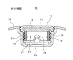
図2には図3に示した第1の実施形態に係る車室内照明装置のB−B断面を示しており、基板17からインナーレンズ12に当接する導電バー18と、光源ケース24と、を含む断面を示している。導電バー18は、インナーレンズ12の端に位置するように光源ケース24によって保持されている。このような構成にすることで、光源21を点灯しない場合には、アウターレンズ11からインナーレンズ12に接続している導電バー18が透けて見えず、光源21を点灯した場合には、光源ケース内で拡散した光がアウターレンズ11を通して車室内を照らすため、導電バーの影がでにくい。
FIG. 2 shows a BB cross section of the vehicle interior lighting device according to the first embodiment shown in FIG. 3, and includes a
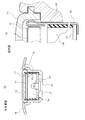
図4は第1の実施形態に係る車室内照明装置の組立図であり、各構成部品について詳説する。車室内照明装置10は図4の下側から、放熱穴を有する筐体16と、光源21〜23を有する基板17と、導電バー18が保持された光源ケース24と、インナーレンズ12が取り付けられたアウターレンズ11と、を有している。次に、組立て手順について説明する。
FIG. 4 is an assembly diagram of the vehicle interior lighting device according to the first embodiment, and each component will be described in detail. The vehicle
最初に、制御回路を有する基板に光源21〜23を取り付ける。筐体16には、基板17の位置決め用のコーナガイド65と固定爪62が設けられており、基板17をコーナガイド65に合わせて筐体16に嵌め込むことで基板17が筐体16に固定される。光源ケース24の固定爪63を基板の固定溝64に嵌るように位置決めした後、光源ケース63を基板17に押し込むことで、光源ケース63が基板17に固定される。次に、インナーレンズ12を取り付けたアウターレンズ11の固定爪67を筐体16の固定溝66に嵌るようにして位置決めした後、筐体16に押し込むことで車室内照明装置の組み立てが終了する。なお、図4の実施形態は、基板17とインナーレンズ12とを電気的に接続する導電バー18は導電バー18の端面が当接することで導通するものである。そこで、車室側から導通バー18がほとんど見えないようにするため、導通バー18を板バネ状にしてインナーレンズ12のレンズ側面に当接させた実施形態について説明する。
First, the
図5は第1の実施形態に係る車室内照明装置10の変型例を示すB−B断面と拡大図を示している。図5の車室内照明装置10は、前述の導体バーの代わりに金属板状の導通板33を使用している。導通板33はL字状に加工され、筐体の内側側面に取り付けられている。光源21を有する基板17が、導通板33のL字状の上に載置されることで基板17の底面側と電気的に接続される。次に、光源ケース33を基板17上に嵌め込むと、導通板33は、筐体16と光源ケース24にて保持される。
インナーレンズ12を嵌め込んだアウターレンズ11を筐体16に取り付ける際、導通板33の先端部に設けられたU字状の端子がインナーレンズ12の側面とアウターレンズ11の側面に嵌り込み、インナーレンズ12の側面に当接することで電極13と電気的に接続され、基板とインナーレンズ12の電極13が接続されることになる。この時、インナーレンズ12の外側側面とアウターレンズ11の内側側面のわずかな隙間に導通板33が収納されることになり、レンズの屈折率の関係で導通板33は目立つことがない。
FIG. 5: has shown the BB cross section and the enlarged view which show the modification of the vehicle
When the
図6は本実施形態に係る車室内照明システム20の回路構成を示し、運転席側車室内照明ユニット30と後席側車室内照明ユニットである車室内照明装置10とが接続されたシステムについて説明する。運転席側車室内照明ユニット30は、ドア開閉に応じて照明を点灯することができるようにドア開閉センサ32と接続されている。また、運転席側車室内照明ユニット30は常時消灯、常時点灯又はドア開閉連動などの点灯モードを設定するスイッチや、他の室内照明装置に点灯モードを伝達するインターフェースを有している。
FIG. 6 shows a circuit configuration of the vehicle
図6の車室内照明装置10は、光源の点灯を制御する制御器31と、搭乗者からの点灯及び消灯指示を検出する左側電極13,中央電極14,右側電極15と、各電極に対応する光源21,22,23と、光源を点灯させるトランジスタ部34と、を有している。また、車室内照明装置10は、運転席側室内照明ユニットからの点灯モードを受信するためのCANバス等の信号線が接続されている。この信号線により、点灯モードに応じて各光源を点灯させることが可能となっている。
The vehicle
図6の制御器31は、各電極の静電容量を所定間隔毎に検出することで、搭乗者の指先の接近具合を判定することが可能であり、複数の電極にわたり静電容量の変化を検出することで、どの光源を点灯又は消灯させるのかを判定することができる。
The
図7は第2の実施形態に係る車室内照明装置40とインナーレンズ42及びアウターレンズ41とを示している。図7の車室内照明装置40は、運転席側車室内照明ユニットからの点灯モードとは独立して設定するモード入力機能をインナーレンズ42の電極で実現したものである。図7の実施形態では、インナーレンズ42に上述した光源の点灯・消灯をさせるための左側電極43,中央電極44,右側電極45の他に、モード入力を可能にするドア連動電極46,消灯電極47,及び点灯電極48と、複数の導光突起部49を点灯させるためにインナーレンズ42の直下に複数のLEDインジケータと、を配置している。本実施形態の特徴事項の一つは、インナーレンズ42の両面にわたる電極を6分割することにより、静電容量の変化により光源の点灯とモード入力を可能にしたことである。
FIG. 7 shows a vehicle
図8は第2の実施形態にアウターレンズ表面のタッチセンサとの組み合わせた第3の実施形態に係る車室内照明装置と、インナーレンズ52及びアウターレンズ51とを示している。図8の車室内照明装置50では、例えば、アウターレンズ51の表面に複数の区分に分けられたタッチセンサ53を配置してモード入力スイッチとして構成し、タッチセンサ53の下面はタッチセンサ用導通バー57により基板の回路に接続されている。また、モード状態を筐体16のLEDインジケータ58によって表示する。このような構成にすることにより、照明は検出範囲の広い浮遊静電方式により光源を点灯させ、モード入力は、タッチセンサにより操作可能とする等、操作性の自由度や意匠の自由度を広げることが可能となる。
FIG. 8 shows a vehicle interior lighting device according to a third embodiment in which the second embodiment is combined with a touch sensor on the outer lens surface, and an
以上、上述したように、本発明の実施形態で示した車室内照明装置は、アウターレンズ(第1のレンズ)の内側に配置され、外側から見えにくいインナーレンズ(第2のレンズ)の電極と基板とを導電バーで接続するようにしたことで、導通バーがアウターレンズを通して搭乗者から見えにくくすることが可能となる。また、搭乗者の触れるアウターレンズ(第1のレンズ)が光源により直接受加熱されることが無く、アウターレンズ(第1のレンズ)の高温化を防止できる。さらに、インナーレンズ(第2のレンズ)の電極を表と裏に形成することが可能になり、電極面積の増加に伴い、検出感度を向上させることが可能となる。 As described above, the vehicle interior lighting device shown in the embodiment of the present invention is arranged on the inner side of the outer lens (first lens), and the electrode of the inner lens (second lens) that is difficult to see from the outer side. By connecting the substrate with the conductive bar, the conductive bar can be made difficult to see from the passenger through the outer lens. In addition, the outer lens (first lens) touched by the passenger is not directly received and heated by the light source, and the temperature of the outer lens (first lens) can be prevented from being increased. Furthermore, the electrodes of the inner lens (second lens) can be formed on the front and back, and the detection sensitivity can be improved as the electrode area increases.
なお、本実施形態では、透明なインナーレンズに設けた電極は赤外線の透過を低減する透明電極としたが、これに限定するものではなく、製品の設計仕様に合わせて乳白色となる電極としても良いし、意匠性を重視して青みがかった電極にしても良いことはいうまでもない。 In this embodiment, the electrode provided on the transparent inner lens is a transparent electrode that reduces the transmission of infrared rays. However, the present invention is not limited to this, and an electrode that turns milky white according to the design specifications of the product may be used. Needless to say, the electrode may be bluish with emphasis on design.
10,40,50,101 車室内照明装置、11,41,51 アウターレンズ、12,42,52 インナーレンズ、13,43 左側電極、14,44 中央電極、15,45 右側電極、16,102 筐体、17,118 基板、18,122 導通バー、19 放熱穴、20 車室内照明システム、21,22,23,116 光源、24,124 光源ケース、30 運転席側車室内照明ユニット、31 制御器、32 ドア開閉センサ、33 導通板、34 トランジスタ部、46 ドア連動電極、47 消灯電極、48 点灯電極、49 導光突起部、53 タッチセンサ、57 タッチセンサ用導通バー、58 LEDインジケータ、62,63,67 固定爪、64,66 固定溝、65 コーナガイド、112,113 照明レンズ、114,115 電極、120 ホルダ、126 内側フレーム、128 外側フレーム。 10, 40, 50, 101 Car interior lighting device, 11, 41, 51 Outer lens, 12, 42, 52 Inner lens, 13, 43 Left electrode, 14, 44 Center electrode, 15, 45 Right electrode, 16, 102 housing Body, 17, 118 substrate, 18, 122 conduction bar, 19 heat radiation hole, 20 vehicle interior lighting system, 21, 22, 23, 116 light source, 24, 124 light source case, 30 driver's seat side vehicle interior lighting unit, 31 controller , 32 Door opening / closing sensor, 33 Conducting plate, 34 Transistor portion, 46 Door interlocking electrode, 47 Light-off electrode, 48 Lighting electrode, 49 Light guide protrusion, 53 Touch sensor, 57 Touch sensor conducting bar, 58 LED indicator, 62, 63, 67 Fixed claw, 64, 66 Fixed groove, 65 Corner guide, 112, 113 Illumination lens, 1 14, 115 electrodes, 120 holder, 126 inner frame, 128 outer frame.
Claims (2)
筐体に固定され、人体が接触可能な第1のレンズと、
光源制御部に接続された基板と、
前記基板に設けられ、少なくとも第1のレンズを通して車内を照らす複数の光源と、
第1のレンズと前記光源との間に設けられた第2のレンズと、
第2のレンズ面に設けられた各光源に対応する透明電極と、
前記透明電極と前記基板とを導通させる導通部材と、
を備え、
前記光源制御部が前記透明電極と人体との静電容量の変化を読み取って前記光源のオンオフを行う車室内照明装置。 A housing fixed to the ceiling of the vehicle;
A first lens fixed to the housing and contactable by a human body;
A substrate connected to the light source controller;
A plurality of light sources provided on the substrate and illuminating the interior of the vehicle through at least a first lens;
A second lens provided between the first lens and the light source;
A transparent electrode corresponding to each light source provided on the second lens surface;
A conducting member for conducting the transparent electrode and the substrate;
With
A vehicle interior lighting device in which the light source control unit reads a change in electrostatic capacitance between the transparent electrode and a human body to turn on and off the light source.
人体との静電容量の変化を読み取る為の電極が設けられた第2のレンズは、薄膜状に形成され、予め決められた波長光を透過する透明電極をおもて面と裏面の両面に有し、第2のレンズを第1のレンズの裏面側に離間して配置することで、光源からの熱が伝わりにくい構造としたことを特徴とする車室内照明装置。 The vehicle interior lighting device according to claim 1,
The second lens provided with an electrode for reading the change in capacitance with the human body is formed in a thin film and has transparent electrodes that transmit light of a predetermined wavelength on both the front and back surfaces. A vehicle interior lighting device having a structure in which heat from the light source is difficult to be transmitted by disposing the second lens on the back side of the first lens.
Priority Applications (1)
| Application Number | Priority Date | Filing Date | Title |
|---|---|---|---|
| JP2010209154A JP5476263B2 (en) | 2010-09-17 | 2010-09-17 | Car interior lighting system |
Applications Claiming Priority (1)
| Application Number | Priority Date | Filing Date | Title |
|---|---|---|---|
| JP2010209154A JP5476263B2 (en) | 2010-09-17 | 2010-09-17 | Car interior lighting system |
Publications (2)
| Publication Number | Publication Date |
|---|---|
| JP2012061997A JP2012061997A (en) | 2012-03-29 |
| JP5476263B2 true JP5476263B2 (en) | 2014-04-23 |
Family
ID=46058159
Family Applications (1)
| Application Number | Title | Priority Date | Filing Date |
|---|---|---|---|
| JP2010209154A Expired - Fee Related JP5476263B2 (en) | 2010-09-17 | 2010-09-17 | Car interior lighting system |
Country Status (1)
| Country | Link |
|---|---|
| JP (1) | JP5476263B2 (en) |
Families Citing this family (9)
| Publication number | Priority date | Publication date | Assignee | Title |
|---|---|---|---|---|
| JP5753515B2 (en) * | 2012-05-16 | 2015-07-22 | 小島プレス工業株式会社 | Automotive lighting system |
| KR101183144B1 (en) * | 2012-05-25 | 2012-09-14 | 실력산업 (주) | A capacitance sensitive touch switch |
| JP6164492B2 (en) * | 2014-05-08 | 2017-07-19 | トヨタ紡織株式会社 | Vehicle lighting device |
| JP2015217906A (en) * | 2014-05-21 | 2015-12-07 | 小島プレス工業株式会社 | Vehicle interior lighting system |
| KR101857326B1 (en) * | 2015-06-23 | 2018-05-11 | 엘에스오토모티브테크놀로지스 주식회사 | Touch-sensitive automotive room lamp module |
| KR101804636B1 (en) * | 2015-10-30 | 2017-12-05 | 엘에스오토모티브 주식회사 | Touch switching unit and an interior ramp module with the same |
| JP6683944B2 (en) * | 2015-12-11 | 2020-04-22 | 東芝ライテック株式会社 | Vehicle interior operation switch |
| JP6652720B2 (en) * | 2017-08-11 | 2020-02-26 | テイ・エス テック株式会社 | Lamp unit and vehicle door |
| JP6652723B2 (en) | 2018-02-20 | 2020-02-26 | テイ・エス テック株式会社 | Lamp unit and vehicle door |
Family Cites Families (1)
| Publication number | Priority date | Publication date | Assignee | Title |
|---|---|---|---|---|
| JP5626868B2 (en) * | 2010-08-25 | 2014-11-19 | 株式会社小糸製作所 | Interior lighting for vehicles |
-
2010
- 2010-09-17 JP JP2010209154A patent/JP5476263B2/en not_active Expired - Fee Related
Also Published As
| Publication number | Publication date |
|---|---|
| JP2012061997A (en) | 2012-03-29 |
Similar Documents
| Publication | Publication Date | Title |
|---|---|---|
| JP5476263B2 (en) | Car interior lighting system | |
| US8878438B2 (en) | Lamp and proximity switch assembly and method | |
| US9641172B2 (en) | Proximity switch assembly having varying size electrode fingers | |
| JP5108602B2 (en) | Car interior lighting system | |
| US20080030465A1 (en) | Removable dial with touch switch control and electroluminescent backlighting | |
| JP6633105B2 (en) | Touch switch unit and vehicle interior lighting device including the same | |
| JP5753515B2 (en) | Automotive lighting system | |
| US10946722B2 (en) | Heater device | |
| US10454474B2 (en) | Proximity switch having sensor with decorative metal | |
| US11801752B2 (en) | Motor vehicle control device | |
| KR101857326B1 (en) | Touch-sensitive automotive room lamp module | |
| KR20180073792A (en) | Touch-sensitive automotive room lamp module | |
| JP2002313181A (en) | Operation panel device | |
| JP5763582B2 (en) | Automotive lighting system | |
| KR200471132Y1 (en) | Room lamp unit for a vehicle | |
| JP5399814B2 (en) | Car interior lighting system | |
| WO2018038291A1 (en) | Touch type room lamp module for vehicle | |
| JP6006526B2 (en) | Automotive lighting system | |
| JP2016055838A (en) | In-vehicle lighting system | |
| US20200108718A1 (en) | Motor vehicle operating device | |
| JP5548030B2 (en) | Vehicle interior light | |
| JP2017084741A (en) | Touch type input device | |
| CN212907505U (en) | Touch switch control assembly | |
| JP2012040970A (en) | Vehicular indoor light | |
| KR101583082B1 (en) | Side light lamp used push-lock switch |
Legal Events
| Date | Code | Title | Description |
|---|---|---|---|
| A621 | Written request for application examination |
Free format text: JAPANESE INTERMEDIATE CODE: A621 Effective date: 20130425 |
|
| TRDD | Decision of grant or rejection written | ||
| A01 | Written decision to grant a patent or to grant a registration (utility model) |
Free format text: JAPANESE INTERMEDIATE CODE: A01 Effective date: 20140204 |
|
| A61 | First payment of annual fees (during grant procedure) |
Free format text: JAPANESE INTERMEDIATE CODE: A61 Effective date: 20140207 |
|
| R150 | Certificate of patent or registration of utility model |
Ref document number: 5476263 Country of ref document: JP Free format text: JAPANESE INTERMEDIATE CODE: R150 Free format text: JAPANESE INTERMEDIATE CODE: R150 |
|
| R250 | Receipt of annual fees |
Free format text: JAPANESE INTERMEDIATE CODE: R250 |
|
| R250 | Receipt of annual fees |
Free format text: JAPANESE INTERMEDIATE CODE: R250 |
|
| R250 | Receipt of annual fees |
Free format text: JAPANESE INTERMEDIATE CODE: R250 |
|
| R250 | Receipt of annual fees |
Free format text: JAPANESE INTERMEDIATE CODE: R250 |
|
| R250 | Receipt of annual fees |
Free format text: JAPANESE INTERMEDIATE CODE: R250 |
|
| LAPS | Cancellation because of no payment of annual fees |