JP5473763B2 - Fixing apparatus and image forming apparatus - Google Patents
Fixing apparatus and image forming apparatus Download PDFInfo
- Publication number
- JP5473763B2 JP5473763B2 JP2010106405A JP2010106405A JP5473763B2 JP 5473763 B2 JP5473763 B2 JP 5473763B2 JP 2010106405 A JP2010106405 A JP 2010106405A JP 2010106405 A JP2010106405 A JP 2010106405A JP 5473763 B2 JP5473763 B2 JP 5473763B2
- Authority
- JP
- Japan
- Prior art keywords
- temperature
- detected
- temperature difference
- comparison result
- threshold value
- Prior art date
- Legal status (The legal status is an assumption and is not a legal conclusion. Google has not performed a legal analysis and makes no representation as to the accuracy of the status listed.)
- Expired - Fee Related
Links
Images


Classifications
-
- G—PHYSICS
- G03—PHOTOGRAPHY; CINEMATOGRAPHY; ANALOGOUS TECHNIQUES USING WAVES OTHER THAN OPTICAL WAVES; ELECTROGRAPHY; HOLOGRAPHY
- G03G—ELECTROGRAPHY; ELECTROPHOTOGRAPHY; MAGNETOGRAPHY
- G03G15/00—Apparatus for electrographic processes using a charge pattern
- G03G15/70—Detecting malfunctions relating to paper handling, e.g. jams
-
- G—PHYSICS
- G03—PHOTOGRAPHY; CINEMATOGRAPHY; ANALOGOUS TECHNIQUES USING WAVES OTHER THAN OPTICAL WAVES; ELECTROGRAPHY; HOLOGRAPHY
- G03G—ELECTROGRAPHY; ELECTROPHOTOGRAPHY; MAGNETOGRAPHY
- G03G15/00—Apparatus for electrographic processes using a charge pattern
- G03G15/20—Apparatus for electrographic processes using a charge pattern for fixing, e.g. by using heat
- G03G15/2003—Apparatus for electrographic processes using a charge pattern for fixing, e.g. by using heat using heat
- G03G15/2014—Apparatus for electrographic processes using a charge pattern for fixing, e.g. by using heat using heat using contact heat
- G03G15/2039—Apparatus for electrographic processes using a charge pattern for fixing, e.g. by using heat using heat using contact heat with means for controlling the fixing temperature
- G03G15/205—Apparatus for electrographic processes using a charge pattern for fixing, e.g. by using heat using heat using contact heat with means for controlling the fixing temperature specially for the mode of operation, e.g. standby, warming-up, error
-
- G—PHYSICS
- G03—PHOTOGRAPHY; CINEMATOGRAPHY; ANALOGOUS TECHNIQUES USING WAVES OTHER THAN OPTICAL WAVES; ELECTROGRAPHY; HOLOGRAPHY
- G03G—ELECTROGRAPHY; ELECTROPHOTOGRAPHY; MAGNETOGRAPHY
- G03G15/00—Apparatus for electrographic processes using a charge pattern
- G03G15/55—Self-diagnostics; Malfunction or lifetime display
Landscapes
- Physics & Mathematics (AREA)
- General Physics & Mathematics (AREA)
- Fixing For Electrophotography (AREA)
Description
本発明は、記録材に転写された未定着トナー像を、記録材に定着して画像形成を行う際に用いられる定着装置、及びこの定着装置を用いた画像形成装置に関する。 The present invention relates to a fixing device used when an unfixed toner image transferred to a recording material is fixed on the recording material to form an image, and an image forming apparatus using the fixing device.
一般に、電子写真プロセスを用いた画像形成装置には、記録材(以下、記録紙とも呼ぶ)に転写された未定着トナー像を加熱・定着する定着装置が備えられており、定着装置に用いられる熱源として様々な種類がある。近年、画像形成装置の起動時におけるウォームアップ時間の短縮が求められており、この関係で、所謂電磁誘導加熱による加熱ヒータ等が熱源として用いられる傾向にある。 In general, an image forming apparatus using an electrophotographic process includes a fixing device that heats and fixes an unfixed toner image transferred to a recording material (hereinafter also referred to as recording paper), and is used in the fixing device. There are various types of heat sources. In recent years, there has been a demand for shortening the warm-up time at the start-up of the image forming apparatus. In this relation, a heater or the like by so-called electromagnetic induction heating tends to be used as a heat source.
定着装置には、一般に、定着ローラ及び加圧ローラが備えられており、定着ローラと加圧ローラとのニップ部に記録紙が搬送されて、記録紙上の未定着トナー像が記録紙に加熱・定着される。 In general, a fixing device includes a fixing roller and a pressure roller. A recording sheet is conveyed to a nip portion between the fixing roller and the pressure roller, and an unfixed toner image on the recording sheet is heated on the recording sheet. It is fixed.
上記の定着ローラは加熱可能であって、定着ローラの表面に配置されたサーミスタ等の温度センサから得られる温度検出信号に基づいて、加熱ヒータがオンオフ制御される。そして、加熱ヒータのオンオフ制御によって定着ローラの表面温度が所定の温度となるように制御が行われる。 The fixing roller can be heated, and the heater is turned on and off based on a temperature detection signal obtained from a temperature sensor such as a thermistor disposed on the surface of the fixing roller. Control is performed so that the surface temperature of the fixing roller becomes a predetermined temperature by ON / OFF control of the heater.
ところで、記録紙はトナーの載り量及び含有する水分量によって不可避的にカールする。そして、記録紙におけるカールの度合いであるカール量に起因して、定着の際、定着ローラに記録紙が巻き付いてしまうことがある。 Incidentally, the recording paper inevitably curls depending on the amount of toner loaded and the amount of water contained. Then, due to the curl amount that is the degree of curl in the recording paper, the recording paper may be wound around the fixing roller at the time of fixing.
記録紙が定着ローラに巻き付いた状態でプリント動作が行われると、定着ローラの表面が記録紙で覆われている関係上、プリント後、記録紙上の画像にガサ付及び定着不良等の画像不良が生じることがある。 If the printing operation is performed with the recording paper wound around the fixing roller, the image on the recording paper will have an image defect such as shading and fixing failure after printing because the surface of the fixing roller is covered with the recording paper. May occur.
また、電磁誘導加熱を用いた加熱ヒータにおいて、定着ローラにキュリー材が用いられていると、定着ローラの表面温度は、定着ローラに巻き付いた記録紙上で検出されることになる。つまり、定着ローラの表面温度が記録紙を介して検出されることになり、この結果、実際の定着ローラの表面温度は温度センサで検出される検出温度よりも高くなる。そして、定着ローラの表面温度がキュリー温度を超える場合がある。 Further, in a heater using electromagnetic induction heating, when a Curie material is used for the fixing roller, the surface temperature of the fixing roller is detected on the recording paper wound around the fixing roller. That is, the surface temperature of the fixing roller is detected through the recording paper, and as a result, the actual surface temperature of the fixing roller is higher than the detection temperature detected by the temperature sensor. In some cases, the surface temperature of the fixing roller exceeds the Curie temperature.
この際、電磁誘導加熱コイルのインピーダンスが急激に減少するため、電磁誘導加熱コイルに過電流が流れて、電源のACヒューズが切れる等の障害が生じることがある。 At this time, since the impedance of the electromagnetic induction heating coil rapidly decreases, an overcurrent may flow through the electromagnetic induction heating coil, causing a failure such as the AC fuse of the power source being blown.
このように、電源に障害が発生すると、その復旧に時間が掛かってしまい、画像形成装置を使用できないダウンタイムが増加することになる。このような不都合を防止するためには、定着ローラに記録紙が巻き付いたことを速やかに検出する必要がある。つまり、記録紙巻き付きの検出時間の短縮化が求められている。 As described above, when a failure occurs in the power source, it takes time to recover the power source, and the downtime in which the image forming apparatus cannot be used increases. In order to prevent such inconvenience, it is necessary to quickly detect that the recording paper has been wound around the fixing roller. That is, there is a demand for shortening the detection time for recording paper winding.
このため、定着装置の入口側及び出口側にそれぞれ記録紙を検知するための記録紙検知センサを設けて、記録紙の巻き付きを検知するようにしたものがある(例えば、特許文献1参照)。 For this reason, a recording paper detection sensor for detecting a recording paper is provided on each of the inlet side and the outlet side of the fixing device to detect winding of the recording paper (for example, see Patent Document 1).
特許文献1においては、記録紙検知センサによる検知結果に応じて、記録紙が定着ローラへ巻き付いたか否かについて判定して、当該判定結果によって定着ローラの駆動を停止するとともに、定着ローラの加熱を停止するようにしている。 In Patent Document 1, it is determined whether or not the recording paper is wound around the fixing roller according to the detection result by the recording paper detection sensor, and the fixing roller is stopped based on the determination result, and the fixing roller is heated. I try to stop.
さらに、ベルト型の定着装置において、通紙領域内に非接触式温度センサを配置するとともに、非通紙領域に接触式温度検知センサを配置するようにしたものがある(例えば、特許文献2参照)。 Further, there is a belt-type fixing device in which a non-contact type temperature sensor is arranged in the paper passing area and a contact type temperature detection sensor is arranged in the non-paper passing area (see, for example, Patent Document 2). ).
特許文献2においては、接触式温度センサによる検出温度が所定の温度となると、非接触式温度センサによる検出温度が所定の温度に到達したか否かに応じて、非接触式温度センサと定着ベルトとの間に記録紙が存在するか否かを判断するようにしている。 In Patent Document 2, when the temperature detected by the contact-type temperature sensor reaches a predetermined temperature, the non-contact-type temperature sensor and the fixing belt depend on whether or not the temperature detected by the non-contact-type temperature sensor has reached the predetermined temperature. It is determined whether or not there is a recording sheet between.
ところで、特許文献1に記載の画像形成装置では、用紙ジャム(例えば、用紙詰まり)が発生すると、ユーザは定着装置を画像形成装置本体から引き出して、ジャム処理を行う。このジャム処理の際、ユーザが定着ローラを手動で回転させて、定着ローラに記録紙が巻き付いた状態にしてしまうことがある。 By the way, in the image forming apparatus described in Patent Document 1, when a paper jam (for example, paper jam) occurs, the user pulls out the fixing device from the main body of the image forming apparatus and performs jam processing. During the jam processing, the user may manually rotate the fixing roller so that the recording paper is wound around the fixing roller.
このような場合に、画像形成装置の電源が再投入されると、定着装置の入口側に配置した検知センサによっては記録紙が検知できないので、定着ローラが加熱されてしまうことになる。 In such a case, when the power of the image forming apparatus is turned on again, the recording sheet cannot be detected by the detection sensor arranged on the entrance side of the fixing apparatus, and the fixing roller is heated.
このような事態を防止するためには、例えば、定着ローラの回転方向を規制する機構等を追加して、ジャム処理の際、ユーザの手動よる定着ローラの回転を規制し、定着ローラに記録紙が巻き付くことを防止する必要がある。しかしながら、このような機構を追加するとなると、不可避的にコストアップとなってしまうという問題点がある。 In order to prevent such a situation, for example, a mechanism for restricting the rotation direction of the fixing roller is added to restrict the rotation of the fixing roller manually by the user at the time of jam processing, and the recording paper is placed on the fixing roller. It is necessary to prevent wrapping. However, when such a mechanism is added, there is a problem that the cost is inevitably increased.
一方、特許文献2に記載の画像形成装置においては、非通紙領域における検出温度が所定の温度に達すると、通紙領域における検出温度が正しいか否かを判断するようにしている。このため、画像形成装置が配置された環境、直前のプリント動作によっては検出温度の設定値(つまり、所定の値)を一意に決めることが困難となる。 On the other hand, in the image forming apparatus described in Patent Document 2, when the detected temperature in the non-sheet passing area reaches a predetermined temperature, it is determined whether or not the detected temperature in the sheet passing area is correct. For this reason, it becomes difficult to uniquely determine a set value (that is, a predetermined value) of the detected temperature depending on the environment in which the image forming apparatus is disposed and the immediately preceding printing operation.
また、非通紙領域における検出温度と、定着ベルトの中央部領域における温度との温度差が大きくても、正常と判断してしまうことがある。そして、非通紙領域に配置された接触式温度センサが定着ベルトに正常に当接されないと、プリント動作の際に定着ベルト端部の温度上昇を検知することができなくなってしまうことになる。 Further, even if the temperature difference between the detected temperature in the non-sheet passing area and the temperature in the central area of the fixing belt is large, it may be determined to be normal. If the contact-type temperature sensor arranged in the non-sheet passing area is not normally brought into contact with the fixing belt, it is impossible to detect the temperature increase at the end of the fixing belt during the printing operation.
よって、特許文献2に記載の画像形成装置においては、定着ベルトの中央部と端部とにおける温度差が大きくなって、記録紙にしわが生じる等の不具合が生じることになってしまう。 Therefore, in the image forming apparatus described in Patent Document 2, the temperature difference between the central portion and the end portion of the fixing belt becomes large, and a problem such as wrinkling of the recording paper occurs.
従って、本発明の目的は、コストアップすることなく、容易に記録紙の巻き付きを検出することのできる定着装置、及びこの定着装置を用いた画像形成装置を提供することにある。 SUMMARY OF THE INVENTION Accordingly, an object of the present invention is to provide a fixing device that can easily detect the winding of a recording sheet without increasing the cost, and an image forming apparatus using the fixing device.
上記の目的を達成するため、本発明による定着装置は、加熱制御されることによりトナー像を記録材に定着するための定着部材と、前記記録材の通紙領域において前記定着部材の温度を検出して第1の検出温度を得る第1の温度検出手段と、前記記録材の非通紙領域において前記定着部材の温度を検出して第2の検出温度を得る第2の温度検出手段と、前記第1及び前記第2の検出温度の温度差と第1の閾値とを比較して第1の比較結果を得る第1の温度差比較手段と、前記温度差と前記第1の閾値よりも大きい第2の閾値とを比較して第2の比較結果を得る第2の温度差比較手段と、前記第2の検出温度に応じて前記第1の比較結果及び前記第2の比較結果のうちいずれか1つを選択する選択手段と、前記選択手段により選択された比較結果に基づいて前記定着部材を加熱制御する加熱制御手段と、を有することを特徴とする。 In order to achieve the above object, a fixing device according to the present invention detects a temperature of a fixing member for fixing a toner image on a recording material by heating control, and a temperature of the fixing member in a sheet passing area of the recording material. First temperature detection means for obtaining a first detection temperature, and second temperature detection means for obtaining a second detection temperature by detecting the temperature of the fixing member in a non-sheet passing region of the recording material, a first temperature difference comparing means for obtaining a first comparison result by comparing the temperature difference between the first threshold of the first and the second detected temperature than the said temperature difference first threshold value A second temperature difference comparing means that compares the second threshold value with a second value to obtain a second comparison result, and the first comparison result and the second comparison result according to the second detected temperature. selection means for selecting one, comparing binding selected by said selection means And having a heating control means for heating controlling the fixing member based on.
また、本発明による画像形成装置は、画像データに応じて記録材にトナー像を転写する転写手段と、加熱制御されることにより、前記転写手段により転写された前記トナー像を前記記録材に定着するための定着部材と、前記記録材の通紙領域において前記定着部材の温度を検出して第1の検出温度を得る第1の温度検出手段と、前記記録材の非通紙領域において前記定着部材の温度を検出して第2の検出温度を得る第2の温度検出手段と、前記第1及び前記第2の検出温度の温度差と第1の閾値とを比較して第1の比較結果を得る第1の温度差比較手段と、前記温度差と前記第1の閾値よりも大きい第2の閾値とを比較して第2の比較結果を得る第2の温度差比較手段と、前記第2の検出温度に応じて前記第1の比較結果及び前記第2の比較結果のうちいずれか1つを選択する選択手段と、前記選択手段により選択された比較結果に基づいて前記定着部材を加熱制御する加熱制御手段と、を有することを特徴とする。 Further, the image forming apparatus according to the present invention fixes the toner image transferred by the transfer means to the recording material by transferring the toner image onto the recording material according to the image data and heating control. A first temperature detecting means for detecting a temperature of the fixing member in the paper passing area of the recording material to obtain a first detected temperature, and the fixing in the non-paper passing area of the recording material. A first comparison result by comparing a temperature difference between the first and second detection temperatures with a first threshold value, a second temperature detection means for detecting a temperature of the member to obtain a second detection temperature; First temperature difference comparing means for obtaining the second difference, second temperature difference comparing means for obtaining a second comparison result by comparing the temperature difference with a second threshold value greater than the first threshold value, The first comparison result and the second comparison according to the detected temperature of 2 Selection means for selecting one of the fruit, characterized by having a a heating control means for heating controlling the fixing member based on the comparison result selected by said selection means.
本発明によれば、通紙領域の第1の検出温度と、非通紙領域の第2の検出温度との差を、所定の閾値と比較して当該温度差が所定の閾値未満であれば、記録紙が定着部材に巻き付いたと判断できるので、容易に記録紙の巻き付きを検出することができる。 According to the present invention, the difference between the first detected temperature in the sheet passing area and the second detected temperature in the non-sheet passing area is compared with a predetermined threshold value, and the temperature difference is less than the predetermined threshold value. , it can be determined that the recording paper is wound around the fixing member, Ru can be detected easily winding the recording paper.
以下、本発明の実施の形態による定着装置の一例を用いた画像形成装置の一例について、図面を参照して説明する。 Hereinafter, an example of an image forming apparatus using an example of a fixing device according to an embodiment of the present invention will be described with reference to the drawings.
図1は、本発明の実施の形態による定着装置の一例を用いた画像形成装置の一例についてその構成を示す図である。 FIG. 1 is a diagram showing the configuration of an example of an image forming apparatus using an example of a fixing device according to an embodiment of the present invention.
図1を参照して、図示の画像形成装置1Aは、本体画像出力部10、本体画像入力部11、及び自動原稿送り装置12を備えている。そして、本体画像出力部10は記録紙(記録材)の上に原稿画像を出力する。また、本体画像入力部11は原稿画像を画像データとして読み取る。そして、画像入力部11の上部に自動原稿送り装置12が配置されている。
Referring to FIG. 1, the illustrated image forming apparatus 1 </ b> A includes a main body
なお、図示のように、画像形成装置には、表示部(操作部ともいう)14が設けられており、この表示部14を用いて、ユーザはコピーモードの設定等の各種設定を行うことができる。さらに、表示部14には、画像形成装置における各種設定値及び現在のジョブ状況が表示される。
As shown in the figure, the image forming apparatus is provided with a display unit (also referred to as an operation unit) 14, and the user can perform various settings such as a copy mode setting using the
本体画像出力部10には、給紙段34、35、36、及び37が備えられており、これら給紙段34、35、36、37にそれぞれ記録紙が収納されている。なお、図示の例では、給紙段34、35、36、及び37には互いに用紙サイズの異なる記録紙が収納されている。
The main body
さらに、図示の例では、本体画像出力部10に大容量のペーパーデッキ15が接続されている。これら記録紙は、選択的にモータ(図示せず)によって駆動される給紙搬送ローラ38、39、40、41、及び42によって画像形成部に搬送される。
Further, in the illustrated example, a large-
例えば、コピーモードの際、自動原稿送り装置12に配置された原稿(又は原稿束)が一枚ずつ原稿台(図示せず)に搬送される。本体画像入力部11は、光源21を有しており、原稿台に配置された原稿に対して、光源21から図中左右方向に光が走査される。
For example, in the copy mode, originals (or original bundles) arranged on the automatic
この光は原稿面で反射されて、その光学像がミラー22、23、及び24とレンズ25とを介して撮像素子(例えば、CCD)26に結像される。CCD26は結像された光学像を電気信号(アナログ画像信号)に変換して、さらに、このアナログ画像信号はA/D変換器によってデジタル画像信号(画像データと呼ぶ)に変換される。そして、この画像データは、ユーザの要求に応じて、例えば、拡大縮小等の画像変換が行われて画像メモリ(図示せず)に格納される。
This light is reflected by the document surface, and its optical image is formed on an image sensor (for example, CCD) 26 via
画像データを出力する際には、本体画像出力部10は画像メモリに格納された画像データを読み出して、この画像データをアナログ画像信号に再変換する。そして、本体画像出力部10は光学照射部27によってアナログ画像信号に応じたレーザビーム(光信号とも呼ぶ)を出力する。このレーザビームはスキャナ28、レンズ29、及びミラー30を介して感光体ドラム31に照射される。つまり、画像データに応じたレーザビームによって感光体ドラム31が走査される。
When outputting image data, the main body
図2は、図1に示す画像形成装置において、感光体ドラム31から定着装置までの構成を拡大して示す図である。
FIG. 2 is an enlarged view showing a configuration from the
図1及び図2を参照して、感光体ドラム31は、その表面に有機光導電体からなる光導電層を有し、コピージョブ中においては所定の速度で図中矢印Aの方向に回転駆動される。
1 and 2, the
まず、感光体ドラム31の残電荷が前露光装置(除電装置ともいう)52によって除去される。そして、一次帯電器51によって感光体ドラム31の表面を一様に帯電する。レーザスキャナユニット50から、前述のレーザビームが感光体ドラム31に照射されて、画像データに応じた静電潜像が感光体ドラム31上形成される。
First, the residual charge on the
なお、図2に示すレーザスキャナユニット50は、例えば、図1に示す光学照射部27、スキャナ28、レンズ29、及びミラー30を有している。
The
続いて、感光体ドラム31上の静電潜像は現像器33によって現像されて、トナー像(可視画像とも呼ぶ)とされる。前述したように、記録紙58が給紙段34、35、36、又は37から紙搬送路を通って搬送され、記録紙58は可視画像に同期して感光体ドラム31の下側を通過する。
Subsequently, the electrostatic latent image on the
この際、転写帯電器55によって記録紙58が帯電されて、感光体ドラム31上の可視画像(トナー像)が記録紙58に転写される。その後、感光体ドラム31と記録紙58との分離性を上げるため、記録紙58は分離帯電器54によって帯電させられる。
At this time, the
感光体ドラム31と分離された記録紙58は、搬送ベルト59によって図中矢印Bの方向に搬送されて、定着装置60Aに至る。定着装置60Aは定着ローラ(定着部材)32及び加圧ローラ43を有しており、定着ローラ32は、例えば、図中矢印Cの方向に回転駆動される。記録紙58は定着ローラ32と加圧ローラ43とのニップ部に導入される。
The
これによって、記録紙58上の未定着トナー像が溶着されて、トナー像が記録紙58上に加熱・定着される。そして、記録紙58は排出ローラ58a等によって排紙トレイ58bに排出される。
As a result, the unfixed toner image on the
転写の後、感光体ドラム31上に残った残トナーは、ドラムクリーナー53によって掻き取られる。そして、感光体ドラム31上の残電荷は前露光装置52によって除去されて、次のコピーに備えることになる。
After the transfer, the residual toner remaining on the
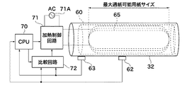
図3は、図2に示す定着装置60Aを拡大して示す図である。図3を参照すると、定着ローラ32は、その内部に誘導加熱コイルホルダ60が配置されている。この誘導加熱コイルホルダ60には誘導加熱コイル(単に、コイルと呼ぶ)65及びフェライトコア66が配置されている。コイル65には電磁誘導加熱電源(図3には示さず)から高周波電流が印加され、コイル65による電磁誘導加熱によって定着ローラ32が加熱される。
FIG. 3 is an enlarged view of the fixing
定着ローラ32の表面温度は、接触式の中央サーミスタ(温度センサとも呼ぶ:第1の温度検出手段)62によって検知される。この中央サーミスタ62は、図中紙面の表側から裏側に向う方向(長手方向)において、定着ローラ32の中央部に配置されている。さらに、中央サーミスタ62は、定着ローラ32と加圧ローラ43とのニップ部を避ける位置に配置されている。
The surface temperature of the fixing
この中央サーミスタ62によって検知された検出温度は、例えば、CPU(図3には示さず)等の制御部に与えられ、後述するようにして、制御部(CPU)は検出温度に基づいて定着ローラ32の温度を所定の温度に制御する。
The detected temperature detected by the
定着ローラ32の周囲は、断熱部材64で覆われており、定着ローラ32で発生する熱を外部に逃がさないようにしている。この定着ローラ32は、例えば、モータ(図示せず)等の駆動源によって回転駆動される。これによって、記録紙58(図2)が定着入口搬送路67上を搬送されて、定着ローラ32と加圧ローラ43とのニップ部を通過して、定着出口搬送路68に搬送される。
The periphery of the fixing
定着出口搬送路68の上側には分離爪61が配置され、この分離爪61によって記録紙58を定着ローラ32から分離する。ところで、分離爪61を定着ローラ32に密着させると、定着ローラ32の表面が傷つくため、定着不良等の不具合が発生する。このため、分離爪61は、例えば、定着ローラ32に対して1mm程度の隙間をおいて配置する必要がある。
A
図4は、図3に示す定着装置60Aに用いられる制御系を説明するためのブロック図である。
FIG. 4 is a block diagram for explaining a control system used in fixing
図4を参照して、図3には示されていないが、定着ローラ32にはその長手方向にそって温度検出用のサーミスタが2つ配置されている。前述の中央サーミスタ62(第1の温度検出手段)は、最小通紙可能用紙サイズにおいて、定着ローラ32の長手方向のほぼ中央部に配置されている。つまり、中央サーミスタ62は通紙領域に配置されている。
Referring to FIG. 4, although not shown in FIG. 3, two temperature detection thermistors are arranged along the longitudinal direction of fixing
一方、端部サーミスタ63(第2の温度検出手段)は、通紙可能な用紙の最大サイズ(最大通紙可能用紙サイズ)の記録紙が定着ローラ32を通過した際の当該記録用紙の端よりも外側に配置されている。つまり、端部サーミスタ63は、通紙領域外(非通紙領域)に配置されている。
On the other hand, the end portion thermistor 63 (second temperature detection means) starts from the end of the recording paper when the recording paper of the maximum size of paper that can be passed (maximum paper passing size) passes through the fixing
このように、端部サーミスタ63が非通紙領域に配置される関係上、余分な熱を発生させないようにするため、コイル65は端部サーミスタ65まで達しないように配置することが望ましい。
Thus, it is desirable to arrange the
中央サーミスタ62及び端部サーミスタ63で検出された定着ローラ32の表面温度は、それぞれ第1及び第2の検出温度としてCPU70及び比較回路72に与えられる。比較回路72は、第1及び第2の検出温度との差を温度差として求めて、後述するように、この温度差と所定の閾値とを比較して複数の比較結果を求める。そして、これら複数の比較結果は、選択的に比較回路出力として加熱制御回路71に与えられる。
The surface temperatures of the fixing
CPU70は比較回路72に対して、切替信号(スイッチング信号)を与え、後述するようにして、比較回路72の出力(比較回路出力)を切り替える。加熱制御回路71は、CPU70の制御下において、比較回路出力に応じてコイル65に印加する電力(例えば、高周波電流)を制御する。
The
図5は、図4に示す比較回路72の構成を示すブロック図である。図4及び図5を参照して、比較回路72は、第1及び第2の温度差検出回路81及び82と切替回路83とを有している。図示のように、中央サーミスタ62及び端部サーミスタ63による検出温度、つまり、第1及び第2の検出温度はそれぞれ第1及び第2の温度差検出回路81及び82に与えられる。なお、第1及び第2の温度差検出回路81及び82はそれぞれ第1及び第2の温度差比較部である。
FIG. 5 is a block diagram showing a configuration of
第1及び第2の温度差検出回路81及び82の各々は、第1及び第2の検出温度の差を示す温度差を求め、この温度差をそれぞれ予め設定された第1及び第2の検出閾値と比較する。そして、第1及び第2の温度差検出回路81及び82はそれぞれ第1及び第2の比較結果を出力する。
Each of the first and second temperature
例えば、温度差がそれぞれ第1及び第2の検出閾値以上であると、第1及び第2の温度差検出回路81及び82はそれぞれ第1及び第2の比較結果としてハイ(High)レベルである信号(以下ハイレベル信号と呼ぶ)を出力する。
For example, if the temperature difference is greater than or equal to the first and second detection threshold values, the first and second temperature
一方、温度差がそれぞれ第1及び第2の検出閾値未満であると、第1及び第2の温度差検出回路81及び82はそれぞれ第1及び第2の比較結果としてロウ(Low)レベルである信号(以下ロウレベル信号と呼ぶ)を出力する。なお、ここでは、第2の検出閾値は第1の検出閾値よりも大きいものとする。
On the other hand, if the temperature difference is less than the first and second detection threshold values, the first and second temperature
第1及び第2の比較結果は、切替回路83に与えられる。切替回路83はCPU70から出力される切替信号によって切替制御され、第1及び第2の比較結果を選択的に比較回路出力(選択比較結果)として加熱制御回路71に与える。
The first and second comparison results are given to the switching
図6は図4に示す加熱制御回路71の構成の一例を示すブロック図である。図6を参照すると、図示の加熱制御回路71は、ANDゲート93、ドライブ回路90、共振出力制御回路91、及びAC整流回路92を備えている。
FIG. 6 is a block diagram showing an example of the configuration of the
CPU70は加熱制御回路71にオン/オフ(ON/OFF)信号を与えており、このON/OFF信号はANDゲート93に与えられる。また、ANDゲート93には前述の比較回路出力が与えられる。ANDゲート93はON/OFF信号と比較回路出力との論理積と求めて、論理積信号としてイネーブル信号を出力する。そして、このイネーブル信号は共振出力制御回路91に与えられる。このイネーブル信号が、例えば、ハイレベルの場合に、共振出力制御回路91はイネーブル状態となる。
The
一方、CPU70は電力制御信号を共振出力制御回路91に出力しており、共振出力制御回路91は電力制御信号とドライブ回路90からフィードバックされる位相検出信号とに応じて、矩形波のPFM(パルス周波数変調)信号を生成する。そして、このPFM信号はドライブ回路90に与えられる。
On the other hand, the
AC整流回路92は、AC電源71Aから入力されるAC電力を整流して、DC電力とする。ドライブ回路90はPFM信号に応じてDC電力を高周波電力に変換するとともに、高周波電力の周波数の位相を検出して、位相検出信号として共振出力制御回路91にフィードバックする。そして、ドライブ回路90は高周波電力をコイル65に与えて、定着ローラ32(図4)を電磁誘導加熱する。
The
図7は、図1に示す画像形成装置の起動時における定着ローラの温度変化の一例を説明するための図である。そして、図7(a)は、通常時(正常時)における定着ローラ32の中央部及び端部の温度変化を示す図であり、図7(b)は通常時において図5に示す中央サーミスタ62及び端部サーミスタ63で検出された検出温度の差分である温度差ΔTの変化を示す図である。なお、ここで、通常時とは、記録紙が定着ローラ32に巻き付いていない状態をいう。
FIG. 7 is a diagram for explaining an example of a temperature change of the fixing roller when the image forming apparatus shown in FIG. 1 is started. FIG. 7A is a diagram showing a temperature change at the central portion and the end portion of the fixing
図7(a)に示すように、画像形成装置を起動した後(電源オンした後)、約40秒で第1の検出温度(中央サーミスタ62による検出温度)が約200度になるまで(破線で示す)、定着ローラ32が加熱される。なお、時間と温度との関係は、この例に限定されない。
As shown in FIG. 7A, after starting the image forming apparatus (after turning on the power), the first detected temperature (detected temperature by the central thermistor 62) reaches about 200 degrees in about 40 seconds (broken line) The fixing
前述のように、端部サーミスタ63はコイル65の位置よりも外側に配置されているため、端部サーミスタ63は暖まりにくい。よって、第2の検出温度(実線で示す)は第1の検出温度(破線で示す)に比べて温度上昇が緩くなる。つまり、第1の検出温度は第2の検出温度よりも常に高く、図7(b)に示す例では、定着ローラ32の加熱開始から約15秒後においては、温度差ΔT>30℃となっている。
As described above, since the
図8は、図1に示す画像形成装置の起動時における定着ローラの温度変化の他の例を説明するための図である。そして、図8(a)は、図2に示す定着ローラ32に記録紙が巻き付いた状態で加熱を開始した際における定着ローラ32の中央部及び端部の温度変化を示す図である。また、図8(b)は、図2に示す定着ローラ32に記録紙が巻き付いた状態で加熱を開始した際において、図5に示す中央サーミスタ62及び端部サーミスタ63で検出された検出温度の差分である温度差ΔTの変化を示す図である。
FIG. 8 is a diagram for explaining another example of the temperature change of the fixing roller when the image forming apparatus shown in FIG. 1 is started. FIG. 8A is a diagram showing temperature changes at the center and end portions of the fixing
図8(a)に示すように、記録紙が定着ローラ32に巻き付いた状態では、中央サーミスタ62と定着ローラ32との間に記録紙が位置する結果、記録紙に熱が奪われる。よって、中央サーミスタ62にとっては、あたかも定着ローラ32の温度が低くみえることになる。その結果、第1の検出温度は、実際の定着ローラ32の表面温度よりも低くなる。
As shown in FIG. 8A, when the recording paper is wound around the fixing
一方、前述のように、端部サーミスタ63は最大通紙可能用紙サイズよりも外側に配置されているので、記録紙が定着ローラ32に巻き付いても端部サーミスタ63に影響を及ぼすことはほとんどない。つまり、定着ローラ32の端部における温度上昇は通常時(正常時)とほとんど変わらない。
On the other hand, as described above, the
このため、第1及び第2の検出温度における上昇カーブはほぼ同様となって、第1及び第2の検出温度の差分である温度差ΔTは、通常時よりも小さくなる。図8(b)に示すように、定着ローラ32の加熱開始から約70秒が経過するまで温度差ΔT<30℃である。
For this reason, the rising curves at the first and second detected temperatures are substantially the same, and the temperature difference ΔT, which is the difference between the first and second detected temperatures, becomes smaller than normal. As shown in FIG. 8B, the temperature difference ΔT <30 ° C. until about 70 seconds elapse after the heating of the fixing
このように、通常時と記録紙が定着ローラ32に巻き付いている状態とを比べると、温度差ΔTの変化は全く異なった挙動を示すことになる。そして、図7(b)及び図8(b)から、温度差(検出温度差ともいう)ΔTが所定の閾値未満であれば記録紙が定着ローラ32に巻き付いた状態と判断することができることがわかる。
As described above, when the normal time and the state in which the recording paper is wound around the fixing
ところで、図7(b)及び図8(b)に示す温度差ΔTの変化は、画像形成装置が設置された環境温度によって変化する。つまり、第1及び第2の検出温度の上昇傾きが環境温度に応じて変化する。 By the way, the change of the temperature difference ΔT shown in FIG. 7B and FIG. 8B changes depending on the environmental temperature where the image forming apparatus is installed. That is, the rising slopes of the first and second detected temperatures change according to the environmental temperature.
例えば、画像形成装置の環境温度が低温であると、定着ローラ32を加熱した際、周囲に熱を奪われる。このため、第1の検出温度が約200℃になるまでに要する時間は、図7(a)に示す約40秒よりも長くなる。この際、当然に、第2の検出温度の上昇に要する時間も図7(a)に比べて長くなる。
For example, if the environmental temperature of the image forming apparatus is low, when the fixing
ところが、前述のように、端部サーミスタ63はコイル65よりも外側に配置されるため、通常時においては、第1の検出温度は第2の検出温度よりも高くなる。さらに、起動時においては、第1及び第2の検出温度ともに上昇カーブを描き、下降カーブを描くことがない。よって、第2の検出温度を基準として、第1及び第2の検出温度の差分を示す温度差ΔTを検知することが望ましい。
However, as described above, since the
図9は、図4に示す端部サーミスタ63の検出温度と中央サーミスタ62及び端部サーミスタ63の検出温度差ΔTとの関係を示す図である。
FIG. 9 is a diagram showing the relationship between the detected temperature of the
図9において、横軸は端部サーミスタ63の検出温度(第2の検出温度)を表し、縦軸は中央サーミスタ62及び端部サーミスタ63の検出温度差ΔTを表す。
In FIG. 9, the horizontal axis represents the detected temperature (second detected temperature) of the
図9に示すように、通常時(記録紙が定着ローラ32に巻き付いていない状態:実線太線で示す)では、第2の検出温度が70℃以上であると、検出温度差ΔTは30℃以上となる。一方、記録紙が定着ローラ32に巻き付いている場合には(実線細線で示す)、常に検出温度差ΔTは30℃以下になることが分かる。 As shown in FIG. 9, in a normal state (a state where the recording paper is not wound around the fixing roller 32: indicated by a solid line), if the second detected temperature is 70 ° C. or higher, the detected temperature difference ΔT is 30 ° C. or higher. It becomes. On the other hand, when the recording paper is wound around the fixing roller 32 (indicated by a solid thin line), it can be seen that the detected temperature difference ΔT is always 30 ° C. or less.
なお、通常時における立ち上げ開始時においては、第1及び第2の検出温度ともに環境温度と同一であるから、検出温度差ΔTは30℃以下となる。このため、第2の検出温度が所定の第1の基準温度(例えば、70℃)以上になった後、検出温度差ΔTが30℃以上となる。よって、第2の検出温度が所定の第1の基準温度以上となるまでエラーと検知しないことが必要である。 Note that at the start of startup in normal times, the first and second detected temperatures are the same as the environmental temperature, and thus the detected temperature difference ΔT is 30 ° C. or less. For this reason, after the second detected temperature becomes equal to or higher than a predetermined first reference temperature (for example, 70 ° C.), the detected temperature difference ΔT becomes 30 ° C. or higher. Therefore, it is necessary not to detect an error until the second detected temperature becomes equal to or higher than the predetermined first reference temperature.
図10は、プリント動作中において、図4に示す中央サーミスタ62及び端部サーミスタ63の検出温度の変化を説明するための図である。
FIG. 10 is a diagram for explaining changes in the detected temperatures of the
図10を参照して、前述のように、中央サーミスタ62は通紙領域に配置されている。そして、通紙領域においては、記録紙によって奪われた熱がコイル65によって補充されて、定着ローラ32の表面温度を一定に保つように制御が行われる。よって、通紙領域においては温度変化が少ないことになる。
Referring to FIG. 10, as described above, the
一方、前述のように、端部サーミスタ63は非通紙領域に配置されている。非通紙領域においては、記録紙に熱が奪われることがない。つまり、放熱量は発熱量に比べて少なくなる。よって、非通紙領域においては、その温度変化が急になる。
On the other hand, as described above, the
図11は、図10に示す状態において、図4に示す端部サーミスタ63の検出温度と中央サーミスタ62及び端部サーミスタ63の検出温度差ΔTとの関係を示す図である。
FIG. 11 is a diagram showing the relationship between the detected temperature of the
図11において、横軸は端部サーミスタ63の検出温度(第2の検出温度)を表し、縦軸は中央サーミスタ62及び端部サーミスタ63の検出温度差ΔTを表す。
In FIG. 11, the horizontal axis represents the detected temperature (second detected temperature) of the
図10及び図11を参照すると、第2の検出温度が上昇すると、検出温度差ΔTが小さくなって、やがて検出温度差ΔTが30℃以下になる。ここでは、第2の検出温度が所定の第2の基準温度(例えば、100℃)以上の場合には、検出温度差ΔTが30℃(閾値:図11に一点鎖線で示す)以下となったとしてもエラーと検知しないようにする必要がある。 Referring to FIG. 10 and FIG. 11, when the second detected temperature increases, the detected temperature difference ΔT becomes smaller and eventually the detected temperature difference ΔT becomes 30 ° C. or less. Here, when the second detected temperature is equal to or higher than a predetermined second reference temperature (for example, 100 ° C.), the detected temperature difference ΔT is 30 ° C. (threshold: indicated by a one-dot chain line in FIG. 11) or less. However, it is necessary not to detect it as an error.
ところで、中央サーミスタ62又は端部サーミスタ63において、途中で断線があると、第1又は第2の検出温度が得られないことになる。同様に、中央サーミスタ62又は端部サーミスタ63が破損すると、第1又は第2の検出温度を正確に検出することができない。このため、検出温度差ΔTが予め規定された温度以上となった際には、中央サーミスタ62又は端部サーミスタ63に異常が生じたことを検知する異常検知回路を設ける。
By the way, if the
例えば、端部サーミスタ63に断線等が生じて、定着ローラ32の温度を検知できなくなった場合、端部サーミスタ63の出力、つまり、第2の検出温度は0℃付近となる。図示の例では、検出温度差ΔT>80℃の場合に、異常(エラー)となる閾値(エラー閾値:図11に二点鎖線で示す)を設定する。
For example, when the
これによって、第1の検出温度が80℃程度となると、エラーとなる。そして、このエラーによって、定着制御を停止するようにすれば、定着ローラ32の温度は80℃程度まで上昇するだけであるから、安全に定着装置の停止を行うことができる。
As a result, an error occurs when the first detection temperature reaches about 80 ° C. If the fixing control is stopped due to this error, the temperature of the fixing
このように、誤検知を生じることなく、記録紙の定着ローラ32への巻き付きを検知して、かつサーミスタの断線等の検知を行う。このため、図示の例では、起動時における温度上昇中に第2の検出温度に応じて、図5に示す切替回路83によって、前述のように、第1及び第2の温度差検出回路81及び82の出力を切替える。
In this manner, the wrapping of the recording paper around the fixing
図12は、図4に示す端部サーミスタ63の検出温度(第2の検出温度)と中央サーミスタ62及び端部サーミスタ63の検出温度差ΔTとに応じた閾値の切り替えを説明するための図である。
FIG. 12 is a diagram for explaining threshold switching according to the detected temperature (second detected temperature) of the
図12において、横軸は端部サーミスタ63の検出温度(第2の検出温度)を表し、縦軸は中央サーミスタ62及び端部サーミスタ63の検出温度差ΔTを表す。
In FIG. 12, the horizontal axis represents the detected temperature (second detected temperature) of the
図5及び図12を参照すると、領域A(第2の温度領域)は、定着ローラ32の加熱開始時から端部サーミスタ63の検出温度(第2の検出温度)が温度Te1(第1の基準温度)に達するまでの領域である。
5 and 12, in the region A (second temperature region), the detected temperature (second detected temperature) of the
この領域Aでは、CPU70は切替回路83を切替制御して、第2の温度差検出回路82を加熱制御回路71と接続する。つまり、領域Aでは、CPU70は第2の温度差検出回路(第2の温度差比較部)82を有効とし、第1の温度差検出回路(第1の温度差比較部)81を無効にする。領域Aにおいては、検出温度差ΔT>温度差ΔT2である場合に検知が行われることになる。
In this region A, the
領域B(第1の温度領域)は、端部サーミスタ63の検出温度(第2の検出温度)が温度Te1以上(第1の基準温度以上)で温度Te2未満(第2の基準温度未満)の領域である。この領域Bでは、CPU70は切替回路83を切替制御して、第1の温度差検出回路81を加熱制御回路71と接続する。つまり、領域Bでは、CPU70は第1の温度差検出回路81を有効とし、第2の温度差検出回路82を無効にする。領域Bにおいては、検出温度差ΔT<温度差ΔT1である場合に検知が行われることになる。
In the region B (first temperature region), the detection temperature (second detection temperature) of the
領域C(第2の温度領域)は、端部サーミスタ63の検出温度(第2の検出温度)が温度Te2以上(第2の基準温度以上)である領域である。この領域Cでは、CPU70は切替回路83を切替制御して、第2の温度差検出回路82を加熱制御回路71と接続する。つまり、領域Cでは、CPU70は第2の温度差検出回路82を有効とし、第1の温度差検出回路81を無効にする。領域Cにおいては、検出温度差ΔT>温度差ΔT2である場合に検知が行われることになる。
Region C (second temperature region) is a region in which the detected temperature (second detected temperature) of
図7及び図8で説明したように、図示の例においては、切替制御を行う際の端部サーミスタ63の検出温度(第2の検出温度)は温度Te1(第1の基準温度)=70℃、温度Te2(第2の基準温度)=100℃程度であることが望ましいが、この温度は単なる一例であり、定着装置等の構成に従って任意に決定するようにすればよい。
As described with reference to FIGS. 7 and 8, in the illustrated example, the detected temperature (second detected temperature) of the
図13は、図9に示す第2の検出温度と検出温度差ΔTとの関係に図12に示す検知範囲を重ねて示す図である。 FIG. 13 is a diagram in which the detection range shown in FIG. 12 is superimposed on the relationship between the second detection temperature and the detection temperature difference ΔT shown in FIG.
図13に示す例では、温度Te1=70℃、温度Te2=100℃とし、温度差ΔT1=30℃、温度差ΔT2=80℃としている。通常時(記録紙の定着ローラ32への巻き付きなしの状態:実線太線で示す)においては、曲線がエラー検知範囲(斜線で示す範囲)に入らない。このため、エラーとはならない。 In the example shown in FIG. 13, the temperature Te1 = 70 ° C., the temperature Te2 = 100 ° C., the temperature difference ΔT1 = 30 ° C., and the temperature difference ΔT2 = 80 ° C. Under normal conditions (the state in which the recording paper is not wound around the fixing roller 32: indicated by a solid thick line), the curve does not enter the error detection range (the range indicated by the oblique line). This is not an error.
一方、記録紙が定着ローラ32に巻き付いた状態では(実線細線で示す)、端部サーミスタ63の検出温度(第2の検出温度)が70℃以上になった場合に、検出温度差ΔTがエラー検知範囲に入る。このため、エラーと検知されることになる。
On the other hand, when the recording paper is wound around the fixing roller 32 (shown by a solid thin line), the detected temperature difference ΔT is an error when the detected temperature (second detected temperature) of the
なお、エラー検知の際には、定着ローラ32による加熱を停止して、例えば、エラー発生した旨を表示部14等に表示して、ユーザに通知する。
When an error is detected, heating by the fixing
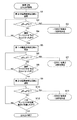
続いて、図4に示す定着装置の動作について説明する。図14は図4に示す定着装置の動作を説明するためのフローチャートである。 Next, the operation of the fixing device shown in FIG. 4 will be described. FIG. 14 is a flowchart for explaining the operation of the fixing device shown in FIG.
図4〜図6及び図14を参照して、いま、電源がオンされて画像形成装置1A(図1)が起動されると、CPU70は切替回路83を切替制御して、第2の温度差検出回路82を加熱制御回路71に接続する。つまり、CPU70は第2の温度差検出回路82を有効にする(ステップS1)。この結果、第2の温度差検出回路82から第2の比較結果が比較回路出力として加熱制御回路71に与えられることになる。
4 to 6 and 14, when the power is turned on and the image forming apparatus 1A (FIG. 1) is activated, the
CPU70は、検出温度差ΔTが温度差ΔT2(第2の温度差閾値)よりも大きいか否かを判定する(ステップS2)。検出温度差ΔTが温度差ΔT2よりも大きいと(ステップS2において、YES)、CPU70は、表示部14(図1)にその旨表示して(ERR2の表示)、加熱制御回路71を制御して(つまり、図6に示すON/OF信号をOFFとして)定着ローラ32の加熱を停止する(第2の停止手段:ステップS3)。
The
一方、検出温度差ΔTが温度差ΔT2以下であると(ステップS2において、NO)、CPU70は、端部サーミスタ63の検出温度(第2の検出温度)が温度Te1以上(第1の基準温度以上)であるか否かについて判定する(ステップS4)。そして、第2の検出温度が温度Te1未満(第1の基準温度未満)であると(ステップS4において、NO)、CPU70は、ステップS2に戻って処理を続行する。
On the other hand, when the detected temperature difference ΔT is equal to or smaller than the temperature difference ΔT2 (NO in step S2), the
第2の検出温度が温度Te1以上であると(ステップS4において、YES)、CPU70は、切替回路83を切替制御して、第1の温度差検出回路81を加熱制御回路71に接続する。つまり、CPU70は第1の温度差検出回路81を有効にする(ステップS5)。この結果、第1の温度差検出回路81から第1の比較結果が比較回路出力として加熱制御回路71に与えられることになる。
When the second detected temperature is equal to or higher than temperature Te1 (YES in step S4),
続いて、CPU70は、検出温度差ΔTが温度差ΔT1(第1の温度差閾値)よりも小さいか否かを判定する(ステップS6)。検出温度差ΔTが温度差ΔT1未満(第1の温度差閾値未満)であると(ステップS6において、YES)、CPU70は、表示部14(図1)にその旨表示して(ERR1の表示)、加熱制御回路71を制御して定着ローラ32の加熱を停止する(第1の停止手段:ステップS7)。
Subsequently, the
検出温度差ΔTが温度差ΔT1以上であると(ステップS6において、NO)、CPU70は、端部サーミスタ63の検出温度(第2の検出温度)が温度Te2以上(第2の基準温度以上)であるか否かについて判定する(ステップS8)。そして、第2の検出温度が温度Te2未満(第2の基準温度未満)であると(ステップS8において、NO)、CPU70は、ステップS6に戻って処理を続行する。
When the detected temperature difference ΔT is equal to or greater than the temperature difference ΔT1 (NO in step S6), the
第2の検出温度が温度Te2以上であると(ステップS8において、YES)、CPU70は、切替回路83を切替制御して、第2の温度差検出回路82を加熱制御回路71に接続する。つまり、CPU70は第2の温度差検出回路82を有効にする(ステップS9)。そして、CPU70は、再び検出温度差ΔTが温度差ΔT2よりも大きいか否かを判定する(ステップS10)。
When the second detected temperature is equal to or higher than temperature Te2 (YES in step S8),
検出温度差ΔTが温度差ΔT2よりも大きいと(ステップS10において、YES)、CPU70は、表示部14(図1)にその旨表示して(ERR2の表示)、加熱制御回路71を制御して定着ローラ32の加熱を停止する(第2の停止手段:ステップS11)。
If detected temperature difference ΔT is larger than temperature difference ΔT2 (YES in step S10),
検出温度差ΔTが温度差ΔT2以下(第2の温度差閾値以下)であると(ステップS10において、NO)、CPU70は、中央サーミスタ62の検出温度(第1の検出温度)が目標温度に達したか否かについて判定する(ステップS12)。そして、第1の検出温度が目標温度未満であると(ステップS12において、NO)、CPU70は、ステップS10に戻って処理を続行する。
When the detected temperature difference ΔT is equal to or less than the temperature difference ΔT2 (less than the second temperature difference threshold value) (NO in step S10), the
一方、第1の検出温度が目標温度に達すると(ステップS12において、YES)、CPU70は、立ち上げを終了する。その後、第2の温度差検出回路82が有効とされた状態で、プリント動作等が行われることになる。
On the other hand, when the first detected temperature reaches the target temperature (YES in step S12),
このように、上述の例では、中央サーミスタ62の検出温度(第1の検出温度)及び端部サーミスタ63の検出温度(第2の検出温度)に応じて第1及び第2の温度差検出回路81及び82の切替制御を行って、記録紙が定着ローラ32に巻き付いたか否かを検知するようにしている。
Thus, in the above-described example, the first and second temperature difference detection circuits according to the detected temperature (first detected temperature) of the
なお、図14に示す動作は、電源スイッチがオンされた際に行われるとしたが、電源スイッチのオンの場合だけではなく、例えば、節電モードからの復帰した場合等、定着装置への通電を行って加熱を開始する場合であれば同様にして適用することができる。つまり、画像形成装置が起動された後にスタンバイ状態に移行する際に図14に示す動作が実行される。 Although the operation shown in FIG. 14 is performed when the power switch is turned on, not only when the power switch is turned on, but also when the fixing device is energized, for example, when returning from the power saving mode. If it is performed and heating is started, it can be applied in the same manner. That is, the operation shown in FIG. 14 is executed when the image forming apparatus is activated and then shifts to the standby state.
上述のようにして、この実施の形態では、検出温度差ΔTに関して、温度差ΔT1(第1の温度差閾値)及びこの温度差ΔT1よりも大きい温度差ΔT2(第2の温度差閾値)を設定する。さらに、端部サーミスタ63の検出温度(第2の検出温度)を基準として、この第2の検出温度に関して、温度Te1(第1の基準温度)と温度Telよりも高い温度Tel(第2の基準温度)を設定する。
As described above, in this embodiment, regarding the detected temperature difference ΔT, the temperature difference ΔT1 (first temperature difference threshold value) and the temperature difference ΔT2 (second temperature difference threshold value) larger than the temperature difference ΔT1 are set. To do. Furthermore, with respect to the detected temperature (second detected temperature) of the
そして、電源がオンされると、CPU70は、第1及び第2の温度差閾値と第1及び第2の基準温度とに応じて、第1及び第2の温度検出回路81及び82の切替制御を行うとともに、定着ローラ32に記録紙が巻き付いた状態であるか否かを判定するようにしている。
When the power is turned on, the
この結果、コストアップすることなく、容易に記録紙の巻き付きを検出することができる。つまり、起動時における定着異常の検知に要する時間を短縮して、加熱停止までの時間を短縮することができる。 As a result, it is possible to easily detect the winding of the recording paper without increasing the cost. That is, it is possible to shorten the time required for detecting the fixing abnormality at the time of activation and to shorten the time until the heating is stopped.
なお、上述の説明から明らかなように、第1及び第2の温度差検出回路81及び82が比較手段として機能する。また、CPU70及び切替回路83が選択手段として機能し、CPU70及び加熱制御回路71が加熱制御手段として機能する。さらに、CPU70が第1の停止手段及び第2の停止手段として機能することになる。
As is apparent from the above description, the first and second temperature
32 定着ローラ
65 コイル
62 中央サーミスタ
63 端部サーミスタ
70 CPU
71 加熱制御回路
72 比較回路
81,82 温度差検出回路
83 切替回路
32
71
Claims (10)
前記記録材の通紙領域において前記定着部材の温度を検出して第1の検出温度を得る第1の温度検出手段と、
前記記録材の非通紙領域において前記定着部材の温度を検出して第2の検出温度を得る第2の温度検出手段と、
前記第1及び前記第2の検出温度の温度差と第1の閾値とを比較して第1の比較結果を得る第1の温度差比較手段と、
前記温度差と前記第1の閾値よりも大きい第2の閾値とを比較して第2の比較結果を得る第2の温度差比較手段と、
前記第2の検出温度に応じて前記第1の比較結果及び前記第2の比較結果のうちいずれか1つを選択する選択手段と、
前記選択手段により選択された比較結果に基づいて前記定着部材を加熱制御する加熱制御手段と、を有することを特徴とする定着装置。 A fixing member for fixing the toner image to the recording material by heating control ;
First temperature detecting means for detecting a temperature of the fixing member in a sheet passing area of the recording material to obtain a first detected temperature;
Second temperature detecting means for detecting a temperature of the fixing member in a non-sheet passing area of the recording material to obtain a second detected temperature;
A first temperature difference comparing means for obtaining a first comparison result by comparing the temperature difference between the first threshold of the first and the second detected temperature,
A second temperature difference comparison means for comparing the temperature difference with a second threshold value greater than the first threshold value to obtain a second comparison result;
Selection means for selecting one of said first comparison result and the second comparison result according to the second detected temperature,
And a heating control unit that controls the heating of the fixing member based on the comparison result selected by the selection unit.
加熱制御されることにより、前記転写手段により転写された前記トナー像を前記記録材に定着するための定着部材と、A fixing member for fixing the toner image transferred by the transfer unit to the recording material by being controlled by heating;
前記記録材の通紙領域において前記定着部材の温度を検出して第1の検出温度を得る第1の温度検出手段と、First temperature detecting means for detecting a temperature of the fixing member in a sheet passing area of the recording material to obtain a first detected temperature;
前記記録材の非通紙領域において前記定着部材の温度を検出して第2の検出温度を得る第2の温度検出手段と、Second temperature detecting means for detecting a temperature of the fixing member in a non-sheet passing area of the recording material to obtain a second detected temperature;
前記第1及び前記第2の検出温度の温度差と第1の閾値とを比較して第1の比較結果を得る第1の温度差比較手段と、A first temperature difference comparing means for comparing the temperature difference between the first and second detected temperatures with a first threshold value to obtain a first comparison result;
前記温度差と前記第1の閾値よりも大きい第2の閾値とを比較して第2の比較結果を得る第2の温度差比較手段と、A second temperature difference comparison means for comparing the temperature difference with a second threshold value greater than the first threshold value to obtain a second comparison result;
前記第2の検出温度に応じて前記第1の比較結果及び前記第2の比較結果のうちいずれか1つを選択する選択手段と、Selecting means for selecting one of the first comparison result and the second comparison result according to the second detected temperature;
前記選択手段により選択された比較結果に基づいて前記定着部材を加熱制御する加熱制御手段と、を有することを特徴とする画像形成装置。An image forming apparatus comprising: a heating control unit configured to control heating of the fixing member based on a comparison result selected by the selection unit.
前記選択手段は、前記第2の検出温度が第1の基準温度以上で当該第1の基準温度より高い第2の基準温度未満である第1の温度領域の際、前記第1の比較結果を選択することを特徴とする請求項6記載の画像形成装置。 When energization of the fixing member is started, the selection unit selects the second comparison result,
In the first temperature range where the second detection temperature is equal to or higher than the first reference temperature and lower than the second reference temperature, the selection means obtains the first comparison result. the image forming apparatus according to claim 6, wherein the selecting.
Priority Applications (5)
| Application Number | Priority Date | Filing Date | Title |
|---|---|---|---|
| JP2010106405A JP5473763B2 (en) | 2010-05-06 | 2010-05-06 | Fixing apparatus and image forming apparatus |
| US13/098,720 US9235182B2 (en) | 2010-05-06 | 2011-05-02 | Fixing device capable of detecting wrap jam of recording sheet and image forming apparatus |
| EP11164728A EP2385428A2 (en) | 2010-05-06 | 2011-05-04 | Fixing device capable of detecting wrap jam of recording sheet and image forming apparatus |
| KR1020110042425A KR101324908B1 (en) | 2010-05-06 | 2011-05-04 | Fixing device capable of detecting wrap jam of recording sheet and image forming apparatus |
| CN2011101174558A CN102236311B (en) | 2010-05-06 | 2011-05-06 | Fixing device and image forming apparatus |
Applications Claiming Priority (1)
| Application Number | Priority Date | Filing Date | Title |
|---|---|---|---|
| JP2010106405A JP5473763B2 (en) | 2010-05-06 | 2010-05-06 | Fixing apparatus and image forming apparatus |
Publications (3)
| Publication Number | Publication Date |
|---|---|
| JP2011237481A JP2011237481A (en) | 2011-11-24 |
| JP2011237481A5 JP2011237481A5 (en) | 2013-06-20 |
| JP5473763B2 true JP5473763B2 (en) | 2014-04-16 |
Family
ID=44343251
Family Applications (1)
| Application Number | Title | Priority Date | Filing Date |
|---|---|---|---|
| JP2010106405A Expired - Fee Related JP5473763B2 (en) | 2010-05-06 | 2010-05-06 | Fixing apparatus and image forming apparatus |
Country Status (5)
| Country | Link |
|---|---|
| US (1) | US9235182B2 (en) |
| EP (1) | EP2385428A2 (en) |
| JP (1) | JP5473763B2 (en) |
| KR (1) | KR101324908B1 (en) |
| CN (1) | CN102236311B (en) |
Families Citing this family (12)
| Publication number | Priority date | Publication date | Assignee | Title |
|---|---|---|---|---|
| US10229348B2 (en) * | 2011-07-05 | 2019-03-12 | Bernard Fryshman | Induction detector systems |
| US10339426B2 (en) * | 2011-07-05 | 2019-07-02 | Bernard Fryshman | Induction system for crowd monitoring |
| JP5494636B2 (en) * | 2011-12-12 | 2014-05-21 | コニカミノルタ株式会社 | Fixing apparatus and image forming apparatus |
| JP6035856B2 (en) * | 2012-05-11 | 2016-11-30 | 富士ゼロックス株式会社 | Fixing apparatus and image forming apparatus |
| CN103885311B (en) * | 2012-12-21 | 2016-01-06 | 株式会社理光 | Fixing device condition detection apparatus and image processing system |
| JP5887285B2 (en) * | 2013-01-28 | 2016-03-16 | 京セラドキュメントソリューションズ株式会社 | Fixing apparatus and image forming apparatus |
| JP5868884B2 (en) * | 2013-02-25 | 2016-02-24 | 京セラドキュメントソリューションズ株式会社 | Heat belt breakage or bias detection method and image forming apparatus |
| JP5836988B2 (en) * | 2013-02-25 | 2015-12-24 | 京セラドキュメントソリューションズ株式会社 | Heat belt breakage or bias detection method and image forming apparatus |
| JP6318890B2 (en) * | 2014-06-10 | 2018-05-09 | 株式会社リコー | Temperature detection device, image forming device |
| JP6516632B2 (en) * | 2015-08-27 | 2019-05-22 | キヤノン株式会社 | Image heating device |
| CN109240053B (en) * | 2018-11-16 | 2021-09-07 | 珠海奔图电子有限公司 | Power supply control apparatus, method and image forming apparatus |
| US10627750B1 (en) * | 2019-01-23 | 2020-04-21 | Toshiba Tec Kabushiki Kaisha | Fixing device and fixing method |
Family Cites Families (28)
| Publication number | Priority date | Publication date | Assignee | Title |
|---|---|---|---|---|
| JPH065434B2 (en) * | 1986-08-22 | 1994-01-19 | シャープ株式会社 | Transfer paper winding detector |
| JPH05289572A (en) * | 1992-04-07 | 1993-11-05 | Canon Inc | Image forming device |
| JP2002156868A (en) * | 2000-09-08 | 2002-05-31 | Ricoh Co Ltd | Image forming device |
| JP2003066768A (en) * | 2001-08-30 | 2003-03-05 | Canon Inc | Image forming apparatus |
| JP2003255753A (en) * | 2002-02-27 | 2003-09-10 | Canon Inc | Heating device and image forming apparatus |
| JP3800118B2 (en) * | 2002-03-27 | 2006-07-26 | ブラザー工業株式会社 | Thermal fixing device and image forming apparatus |
| JP2004021186A (en) * | 2002-06-20 | 2004-01-22 | Canon Finetech Inc | Fixing device |
| JP2004361715A (en) * | 2003-06-05 | 2004-12-24 | Konica Minolta Business Technologies Inc | Abnormal temperature detecting device and image forming apparatus |
| US7062187B2 (en) * | 2002-10-31 | 2006-06-13 | Konica Minolta Holdings, Inc. | Fixing device for use in image forming apparatus |
| US6861630B2 (en) * | 2003-03-07 | 2005-03-01 | Kabushiki Kaisha Toshiba | Heating device and fixing device |
| JP2004354983A (en) | 2003-05-01 | 2004-12-16 | Canon Inc | Image heating device with mechanism for preventing winding of recording medium around fixing rotor |
| JP2005257945A (en) * | 2004-03-10 | 2005-09-22 | Matsushita Electric Ind Co Ltd | Image heating device |
| JP2006251488A (en) | 2005-03-11 | 2006-09-21 | Ricoh Co Ltd | Heat belt fixing apparatus |
| US7242880B2 (en) | 2005-03-17 | 2007-07-10 | Kabushiki Kaisha Toshiba | Fixing apparatus and heating apparatus control method |
| JP2007086208A (en) * | 2005-09-20 | 2007-04-05 | Sharp Corp | Fixing device and image forming apparatus |
| JP4307438B2 (en) * | 2005-11-28 | 2009-08-05 | シャープ株式会社 | Fixing apparatus and image forming apparatus |
| JP4403136B2 (en) * | 2005-12-09 | 2010-01-20 | シャープ株式会社 | FIXING DEVICE, IMAGE FORMING DEVICE EQUIPPED WITH THE FIXING DEVICE, AND CONTROL METHOD FOR FIXING DEVICE |
| JP2007279636A (en) * | 2006-04-12 | 2007-10-25 | Toshiba Corp | Image forming apparatus |
| JP4829700B2 (en) * | 2006-06-29 | 2011-12-07 | パナソニック株式会社 | Fixing apparatus, image forming apparatus using the same, and abnormality determination method |
| US7546051B2 (en) * | 2007-04-17 | 2009-06-09 | Kabushiki Kaisha Toshiba | Fixing apparatus and image processing apparatus |
| JP2008281743A (en) * | 2007-05-10 | 2008-11-20 | Ricoh Co Ltd | Image forming apparatus, image forming method, image forming program and recording medium |
| US7599637B2 (en) * | 2007-07-27 | 2009-10-06 | Canon Kabushiki Kaisha | Image fixing apparatus |
| JP5424012B2 (en) * | 2008-08-27 | 2014-02-26 | 株式会社リコー | Fixing device control method, fixing device, and image forming apparatus |
| JP5299847B2 (en) * | 2009-07-27 | 2013-09-25 | 株式会社リコー | Fixing apparatus and image forming apparatus |
| JP5264818B2 (en) * | 2009-07-29 | 2013-08-14 | 京セラドキュメントソリューションズ株式会社 | Fixing device and image forming apparatus having the same |
| JP5679100B2 (en) * | 2009-09-14 | 2015-03-04 | 株式会社リコー | Fixing apparatus and image forming apparatus |
| JP5661435B2 (en) * | 2009-12-11 | 2015-01-28 | シャープ株式会社 | Fixing apparatus, image forming apparatus, temperature control method for fixing apparatus, program, and recording medium therefor |
| JP5574748B2 (en) * | 2010-02-24 | 2014-08-20 | キヤノン株式会社 | Fixing apparatus and image forming apparatus |
-
2010
- 2010-05-06 JP JP2010106405A patent/JP5473763B2/en not_active Expired - Fee Related
-
2011
- 2011-05-02 US US13/098,720 patent/US9235182B2/en not_active Expired - Fee Related
- 2011-05-04 KR KR1020110042425A patent/KR101324908B1/en not_active IP Right Cessation
- 2011-05-04 EP EP11164728A patent/EP2385428A2/en not_active Withdrawn
- 2011-05-06 CN CN2011101174558A patent/CN102236311B/en not_active Expired - Fee Related
Also Published As
| Publication number | Publication date |
|---|---|
| CN102236311A (en) | 2011-11-09 |
| KR20110123219A (en) | 2011-11-14 |
| US9235182B2 (en) | 2016-01-12 |
| CN102236311B (en) | 2013-11-27 |
| KR101324908B1 (en) | 2013-11-04 |
| EP2385428A2 (en) | 2011-11-09 |
| JP2011237481A (en) | 2011-11-24 |
| US20110274446A1 (en) | 2011-11-10 |
Similar Documents
| Publication | Publication Date | Title |
|---|---|---|
| JP5473763B2 (en) | Fixing apparatus and image forming apparatus | |
| JP4634487B2 (en) | Image forming apparatus | |
| US20090263151A1 (en) | Image forming apparatus, printing method applicable to image forming apparatus, and computer program for implementing a printing process carried out by image forming apparatus | |
| JP5258453B2 (en) | Image forming apparatus and power control method thereof | |
| JP2008089986A (en) | Image forming apparatus | |
| JP2010244051A (en) | Fixing device, image reading apparatus and method for detecting failure of the fixing device | |
| JP6274133B2 (en) | Image forming apparatus | |
| JP2011107447A (en) | Image forming apparatus | |
| JP5353019B2 (en) | Image forming apparatus | |
| JP2007140330A (en) | Image forming apparatus | |
| JP6507831B2 (en) | Fixing device and image forming apparatus | |
| JP5574791B2 (en) | Image forming apparatus | |
| JP4810981B2 (en) | Image forming apparatus | |
| JP7353759B2 (en) | Fixing device and image forming device | |
| JPH06202522A (en) | Image forming device | |
| JP2011033997A (en) | Image heating device | |
| JP2011033808A (en) | Image forming apparatus | |
| JP2007148194A (en) | Image forming apparatus | |
| JPH06194993A (en) | Image forming device and fixing device | |
| JPH08314321A (en) | Image recorder provided with temperature controller for thermal roller type fixing unit | |
| JP2024124901A (en) | Fixing device and image forming apparatus equipped with same | |
| JP6572599B2 (en) | Image forming apparatus | |
| JP2005165143A (en) | Image forming apparatus | |
| JP2019028262A (en) | Heating apparatus and image formation device | |
| JP2021071592A (en) | Fixing device |
Legal Events
| Date | Code | Title | Description |
|---|---|---|---|
| A521 | Request for written amendment filed |
Free format text: JAPANESE INTERMEDIATE CODE: A523 Effective date: 20130507 |
|
| A621 | Written request for application examination |
Free format text: JAPANESE INTERMEDIATE CODE: A621 Effective date: 20130507 |
|
| A977 | Report on retrieval |
Free format text: JAPANESE INTERMEDIATE CODE: A971007 Effective date: 20131219 |
|
| TRDD | Decision of grant or rejection written | ||
| A01 | Written decision to grant a patent or to grant a registration (utility model) |
Free format text: JAPANESE INTERMEDIATE CODE: A01 Effective date: 20140107 |
|
| A61 | First payment of annual fees (during grant procedure) |
Free format text: JAPANESE INTERMEDIATE CODE: A61 Effective date: 20140204 |
|
| LAPS | Cancellation because of no payment of annual fees |