JP5473323B2 - Apparatus for mixing and distributing gas and liquid upstream from a particle packed bed - Google Patents
Apparatus for mixing and distributing gas and liquid upstream from a particle packed bed Download PDFInfo
- Publication number
- JP5473323B2 JP5473323B2 JP2008501348A JP2008501348A JP5473323B2 JP 5473323 B2 JP5473323 B2 JP 5473323B2 JP 2008501348 A JP2008501348 A JP 2008501348A JP 2008501348 A JP2008501348 A JP 2008501348A JP 5473323 B2 JP5473323 B2 JP 5473323B2
- Authority
- JP
- Japan
- Prior art keywords
- liquid
- plate
- gas
- riser
- lower plate
- Prior art date
- Legal status (The legal status is an assumption and is not a legal conclusion. Google has not performed a legal analysis and makes no representation as to the accuracy of the status listed.)
- Active
Links
- 239000007788 liquid Substances 0.000 title claims description 171
- 239000002245 particle Substances 0.000 title claims description 29
- 238000011144 upstream manufacturing Methods 0.000 title claims description 10
- 238000002156 mixing Methods 0.000 title claims description 8
- 239000007789 gas Substances 0.000 claims description 132
- 238000000926 separation method Methods 0.000 claims description 17
- 238000004891 communication Methods 0.000 claims description 5
- 239000012530 fluid Substances 0.000 description 16
- 239000000203 mixture Substances 0.000 description 14
- 238000006243 chemical reaction Methods 0.000 description 12
- 150000001875 compounds Chemical class 0.000 description 4
- 238000005984 hydrogenation reaction Methods 0.000 description 4
- 239000007791 liquid phase Substances 0.000 description 4
- 239000007787 solid Substances 0.000 description 4
- 230000005587 bubbling Effects 0.000 description 3
- 238000012546 transfer Methods 0.000 description 3
- 238000004517 catalytic hydrocracking Methods 0.000 description 2
- 238000001311 chemical methods and process Methods 0.000 description 2
- 238000005187 foaming Methods 0.000 description 2
- 238000000034 method Methods 0.000 description 2
- 239000000126 substance Substances 0.000 description 2
- XLYOFNOQVPJJNP-UHFFFAOYSA-N water Substances O XLYOFNOQVPJJNP-UHFFFAOYSA-N 0.000 description 2
- UFWIBTONFRDIAS-UHFFFAOYSA-N Naphthalene Chemical compound C1=CC=CC2=CC=CC=C21 UFWIBTONFRDIAS-UHFFFAOYSA-N 0.000 description 1
- NINIDFKCEFEMDL-UHFFFAOYSA-N Sulfur Chemical compound [S] NINIDFKCEFEMDL-UHFFFAOYSA-N 0.000 description 1
- 238000009825 accumulation Methods 0.000 description 1
- 125000001931 aliphatic group Chemical group 0.000 description 1
- 150000001336 alkenes Chemical class 0.000 description 1
- 238000005576 amination reaction Methods 0.000 description 1
- 230000003321 amplification Effects 0.000 description 1
- 125000003118 aryl group Chemical group 0.000 description 1
- 230000015572 biosynthetic process Effects 0.000 description 1
- 230000003197 catalytic effect Effects 0.000 description 1
- 230000008859 change Effects 0.000 description 1
- 238000005660 chlorination reaction Methods 0.000 description 1
- 239000012809 cooling fluid Substances 0.000 description 1
- 230000007547 defect Effects 0.000 description 1
- 230000001627 detrimental effect Effects 0.000 description 1
- 238000004090 dissolution Methods 0.000 description 1
- 230000009977 dual effect Effects 0.000 description 1
- 230000000694 effects Effects 0.000 description 1
- 239000000839 emulsion Substances 0.000 description 1
- 238000002474 experimental method Methods 0.000 description 1
- 239000006260 foam Substances 0.000 description 1
- 238000005658 halogenation reaction Methods 0.000 description 1
- 229910052739 hydrogen Inorganic materials 0.000 description 1
- 239000001257 hydrogen Substances 0.000 description 1
- 125000004435 hydrogen atom Chemical class [H]* 0.000 description 1
- 238000007654 immersion Methods 0.000 description 1
- 230000006872 improvement Effects 0.000 description 1
- 238000002347 injection Methods 0.000 description 1
- 239000007924 injection Substances 0.000 description 1
- 238000003199 nucleic acid amplification method Methods 0.000 description 1
- 238000005457 optimization Methods 0.000 description 1
- 238000007254 oxidation reaction Methods 0.000 description 1
- 238000012856 packing Methods 0.000 description 1
- 238000000053 physical method Methods 0.000 description 1
- 238000011197 physicochemical method Methods 0.000 description 1
- 230000008569 process Effects 0.000 description 1
- 238000010791 quenching Methods 0.000 description 1
- 230000000171 quenching effect Effects 0.000 description 1
- 229910052717 sulfur Inorganic materials 0.000 description 1
- 239000011593 sulfur Substances 0.000 description 1
Images


Classifications
-
- B—PERFORMING OPERATIONS; TRANSPORTING
- B01—PHYSICAL OR CHEMICAL PROCESSES OR APPARATUS IN GENERAL
- B01J—CHEMICAL OR PHYSICAL PROCESSES, e.g. CATALYSIS OR COLLOID CHEMISTRY; THEIR RELEVANT APPARATUS
- B01J8/00—Chemical or physical processes in general, conducted in the presence of fluids and solid particles; Apparatus for such processes
- B01J8/02—Chemical or physical processes in general, conducted in the presence of fluids and solid particles; Apparatus for such processes with stationary particles, e.g. in fixed beds
- B01J8/04—Chemical or physical processes in general, conducted in the presence of fluids and solid particles; Apparatus for such processes with stationary particles, e.g. in fixed beds the fluid passing successively through two or more beds
- B01J8/0492—Feeding reactive fluids
-
- B—PERFORMING OPERATIONS; TRANSPORTING
- B01—PHYSICAL OR CHEMICAL PROCESSES OR APPARATUS IN GENERAL
- B01D—SEPARATION
- B01D53/00—Separation of gases or vapours; Recovering vapours of volatile solvents from gases; Chemical or biological purification of waste gases, e.g. engine exhaust gases, smoke, fumes, flue gases, aerosols
- B01D53/14—Separation of gases or vapours; Recovering vapours of volatile solvents from gases; Chemical or biological purification of waste gases, e.g. engine exhaust gases, smoke, fumes, flue gases, aerosols by absorption
- B01D53/18—Absorbing units; Liquid distributors therefor
- B01D53/185—Liquid distributors
-
- B—PERFORMING OPERATIONS; TRANSPORTING
- B01—PHYSICAL OR CHEMICAL PROCESSES OR APPARATUS IN GENERAL
- B01F—MIXING, e.g. DISSOLVING, EMULSIFYING OR DISPERSING
- B01F23/00—Mixing according to the phases to be mixed, e.g. dispersing or emulsifying
- B01F23/20—Mixing gases with liquids
-
- B—PERFORMING OPERATIONS; TRANSPORTING
- B01—PHYSICAL OR CHEMICAL PROCESSES OR APPARATUS IN GENERAL
- B01J—CHEMICAL OR PHYSICAL PROCESSES, e.g. CATALYSIS OR COLLOID CHEMISTRY; THEIR RELEVANT APPARATUS
- B01J8/00—Chemical or physical processes in general, conducted in the presence of fluids and solid particles; Apparatus for such processes
- B01J8/008—Details of the reactor or of the particulate material; Processes to increase or to retard the rate of reaction
-
- C—CHEMISTRY; METALLURGY
- C10—PETROLEUM, GAS OR COKE INDUSTRIES; TECHNICAL GASES CONTAINING CARBON MONOXIDE; FUELS; LUBRICANTS; PEAT
- C10G—CRACKING HYDROCARBON OILS; PRODUCTION OF LIQUID HYDROCARBON MIXTURES, e.g. BY DESTRUCTIVE HYDROGENATION, OLIGOMERISATION, POLYMERISATION; RECOVERY OF HYDROCARBON OILS FROM OIL-SHALE, OIL-SAND, OR GASES; REFINING MIXTURES MAINLY CONSISTING OF HYDROCARBONS; REFORMING OF NAPHTHA; MINERAL WAXES
- C10G49/00—Treatment of hydrocarbon oils, in the presence of hydrogen or hydrogen-generating compounds, not provided for in a single one of groups C10G45/02, C10G45/32, C10G45/44, C10G45/58 or C10G47/00
- C10G49/002—Apparatus for fixed bed hydrotreatment processes
Description
本発明は、少なくとも1つの粒子充填層を含む筐体の内側に一般的に配置される球形装置に関する。本発明の適用分野は、化学、物理または物理化学方法における粒子充填層の使用を含む。本発明は、より特定的には、筐体内に一般的に取り付けられ、粒子充填層の表面において流体を一様に分配することを目的とする球形の分配プレートに関する。 The present invention relates to a spherical device generally disposed inside a housing that includes at least one particle packed bed. The field of application of the invention includes the use of particle packed beds in chemical, physical or physicochemical methods. The present invention more particularly relates to a spherical distribution plate that is generally mounted in a housing and aims to distribute fluid evenly on the surface of a particle packed bed.
特許文献1には、反応器内において粒子充填層から上流に配置される、液体状流体およびガス状流体を混合および分配するための装置が記載されている。この特許に記載された装置は、ライザを備えたプレートを含み、該ライザは、プレートの上方に開口する上部と、プレートの下側と連絡する下端部とを備え、ライザの上部には、側部オリフィスが備えられている。この装置では、液体は、管状システムによって反応器の外側から分配プレートに運ばれ、その結果、該管状システムの下端部は、プレートの上に蓄積した液体に浸かったままである。 Patent Document 1 describes an apparatus for mixing and distributing a liquid fluid and a gaseous fluid disposed upstream from a particle packed bed in a reactor. The device described in this patent includes a plate with a riser, the riser comprising an upper portion opening above the plate and a lower end communicating with the lower side of the plate, the upper portion of the riser having a side Partial orifices are provided. In this device, the liquid is carried by the tubular system from the outside of the reactor to the distribution plate, so that the lower end of the tubular system remains immersed in the liquid accumulated on the plate.
このようなシステムの欠点は、ガスおよび液体が別々に反応器に持ち込まれることである。事実、気体状流体と液体状流体とからなる混合物を分配する前に、反応器の断面全体にわたって均一にこれらの流体の接触を最大にすることがしばしば望ましい。ガスおよび液体の混合物が接触床中を流れる前でさえ、気体状流体からの反応性化合物により液体供給材料を飽和させることが、しばしば、特に、化学方法の場合において重要である。 The disadvantage of such a system is that gas and liquid are brought separately into the reactor. In fact, before dispensing a mixture of gaseous and liquid fluids, it is often desirable to maximize contact of these fluids uniformly across the cross section of the reactor. It is often important, especially in the case of chemical processes, to saturate liquid feeds with reactive compounds from gaseous fluids, even before the gas and liquid mixture flows in the contact bed.
このようなシステムのさらなる欠点は、管状システムを満たすために相当量の液体によってのみそれが装填され得ることである。したがって、液体の速度は管状システムの下端部またはこの端部の延長部を形成する管のオリフィスにおいて高い。これは、ガスと液体との間の界面の混乱の源であり得、これは、一方でガスおよび液体の混合の均一性および他方で層の上表面でのこのような混合物の分配の均一性を危うくする。 A further disadvantage of such a system is that it can only be loaded with a substantial amount of liquid to fill the tubular system. Thus, the liquid velocity is high at the lower end of the tubular system or at the orifice of the tube forming an extension of this end. This can be a source of disruption of the interface between the gas and the liquid, which on the one hand the uniformity of the mixing of the gas and liquid and on the other hand the uniformity of the distribution of such a mixture on the upper surface of the layer Endanger.
特許文献2には、固体の固定床の表面を通してガスおよび液体を駆動し、分配プレートと、該プレートを貫通して延びる複数の管とを含み、該管のそれぞれは、プレートの上面上に垂直に延びる複数の側部オリフィスを備えた分配システムであって、これらの管の2つの群がそれらの側部オリフィスの垂直位置によって特徴付けられるものが記載されている。この特許出願に記載される装置は、2つの群の管の側部オリフィスの位置のお陰で、前記プレート上に蓄積する液体の高さが、所定レベル(このレベルより下では、管の群の一方が側部オリフィスを含まない)に達する時にプレートを貫通して流れる液体の流れを低減させることを可能にする。さらに、ガスおよび液体は、前記プレートおよびこれらの管の基部に提供されるスロットの上面上に取り付けられた垂直管によって分配プレートに運ばれる。 U.S. Patent No. 6,057,049 drives gas and liquid through the surface of a solid fixed bed and includes a distribution plate and a plurality of tubes extending through the plate, each of the tubes being perpendicular to the upper surface of the plate. A distribution system with a plurality of side orifices extending to the top is described, wherein two groups of these tubes are characterized by the vertical position of their side orifices. Thanks to the position of the side orifices of the two groups of tubes, the device described in this patent application allows the height of the liquid that accumulates on the plate to be below a predetermined level (below this level of the group of tubes). Makes it possible to reduce the flow of liquid flowing through the plate when one reaches the side). In addition, gases and liquids are carried to the distribution plate by vertical tubes mounted on the top surfaces of the plates and slots provided in the bases of these tubes.
このようなシステムの欠点は、ガスおよび液体が、混合物として分配プレートの上面上に送り込まれることである。この導入様式は、液体中でのガスのバブリングに一部起因して、ガスと液体との間の界面における混乱を生じさせる。
(発明の要約)
本発明の1つの目的は、筐体内に取り付けられ、粒子充填層から上流または2つの連続する粒子充填層の間でガスおよび液体の混合および分配を最適化することを可能にする装置を提供することである。
(Summary of the Invention)
One object of the present invention is to provide an apparatus that is mounted in a housing and that enables optimization of gas and liquid mixing and distribution upstream from a particle packed bed or between two successive particle packed beds. That is.
本発明の別の目的は、ガスおよび液体の反応筐体への導入、さらには粒子充填層上でのこのガスおよびこの液体の均一な再分配を可能にする装置を提供することである。 Another object of the present invention is to provide an apparatus that allows the introduction of gas and liquid into the reaction enclosure as well as the uniform redistribution of the gas and liquid on the particle packed bed.
本発明の別の目的は、ガスおよび液体の混合物注入点から上流の粒子充填層の入口におけるガスおよび液体の間の物質移動を最大にすることである。化学的方法の場合、これは、ガスから液体への反応性化合物の移動を有利にすることを可能にする。反応が概して液体中で起こる化学的方法において、この化合物のガスから液体への移動は、反応方法を制限する要因であり得る。本発明は、ガスと液体の間の界面における均一な気泡雲の形成を有利にすることによって、ガスと液体との間のこの移動を増加させることを可能にする。 Another object of the present invention is to maximize mass transfer between the gas and liquid at the inlet of the particle packed bed upstream from the gas and liquid mixture injection point. In the case of chemical methods, this makes it possible to favor the transfer of reactive compounds from gas to liquid. In chemical processes where the reaction generally takes place in a liquid, the transfer of this compound from the gas to the liquid can be a limiting factor in the reaction process. The present invention makes it possible to increase this movement between gas and liquid by favoring the formation of a uniform bubble cloud at the interface between gas and liquid.
本発明の別の目的は、粒子充填層の表面におけるガスおよび液体の分配均一性に有害であり得るあらゆる不安定なまたは局所的なバブリングまたは発泡現象を妨げることを可能にするガスおよび液体の分配プレートを提供することである。 Another object of the present invention is the gas and liquid distribution that makes it possible to prevent any unstable or local bubbling or foaming phenomena that can be detrimental to the gas and liquid distribution uniformity at the surface of the particle packed bed. To provide a plate.
前述の目的に加えて、本発明は、床の上部表面においてガスおよび液体を含む混合物の分配の均一性を改善することにある技術的問題を少なくとも解決することを可能にする。 In addition to the foregoing objects, the present invention makes it possible to at least solve the technical problem of improving the uniformity of the distribution of mixtures containing gases and liquids at the upper surface of the bed.
それ故に、本発明は、ガスおよび液体を混合および分配するための、粒子充填層から上流に配置される装置であって、下部プレートと、上部プレートを備えたガスおよび液体送達手段とを含み、下部プレートは、複数のライザを備え、各ライザは、少なくとも1つの側部オリフィスを備えた上部と、該下部プレートの下側と連絡する(communicate)下部とを含み、上部プレートは、液体を下部プレートに搬送する手段と、ガス分離および搬送手段とを備える、装置に関する。
Therefore, the present invention is an apparatus disposed upstream from a particle packed bed for mixing and distributing gases and liquids, comprising a lower plate, and gas and liquid delivery means with an upper plate, The lower plate includes a plurality of risers, each riser including an upper portion with at least one side orifice and a lower portion in communication with the lower side of the lower plate, the upper plate having a lower liquid. and means for conveying the plate, and a gas separation and transport means, to an apparatus.
一つの実施形態において、液体を下部プレートに搬送する手段は、前記上部プレートの表面上に一様に分配されるオリフィスを含む。 In one embodiment, the means for transporting liquid to the lower plate includes an orifice that is uniformly distributed over the surface of the upper plate.
あるいは、液体を下部プレートに搬送するためのこれらの手段は、上部プレートを貫通して提供される少なくとも1つのラインであって、その端部が、一端については下部プレートのレベルに蓄積する液体中に、他端については上部プレートのレベルに蓄積する液体中に浸されるように配置されるラインを含み得る。 Alternatively, these means for transporting the liquid to the lower plate are at least one line provided through the upper plate, the end of which in the liquid accumulates at the level of the lower plate for one end. In addition, the other end may include a line arranged to be immersed in a liquid that accumulates at the level of the upper plate.
別の実施形態において、ガス分離および搬送手段は、両端において開口し、上部プレートを貫通して配置された管であって、その上端は、ガスのみの通過を可能にするようにカバーを備えた、管を含む。 In another embodiment, the gas separating and conveying means is a tube that opens at both ends and is disposed through the top plate, the upper end of which is provided with a cover to allow only gas to pass through. Including tubes.
さらに別の実施形態において、ガスを上部プレートの下に搬送するための分離手段は、上部プレートの周辺上に提供されかつリムを備えた環状開口と、ガスのみの通過を可能にするように前記開口を覆うカバーとを含む。
In yet another embodiment, the separating means for transporting gas under the top plate is provided on the periphery of the top plate and provided with a rim, and the said means to allow the passage of gas only. including a cover for covering the opening.
本発明による装置の他の特徴および利点は、添付の図面を参照しながら以降の実施形態の記載を読み取ることから明らかになる。 Other features and advantages of the device according to the invention will become apparent from reading the description of the following embodiments with reference to the accompanying drawings.
(発明の詳細な説明)
それ故に、本発明は、粒子充填層から上流に配置される、ガスおよび液体を混合および分配するための装置であって、ガスおよび液体の送達手段と、実質的に水平な下部プレートとを含み、前記下部プレートは、前記プレートの表面上に一様に分配される複数のライザを備え、各ライザは、上部、および該プレートの下側と連絡する下端を含み、ライザの上部は、少なくとも1つの側部オリフィスを備える、装置に関する。
(Detailed description of the invention)
Therefore, the present invention is an apparatus for mixing and dispensing gases and liquids disposed upstream from a particle packed bed, comprising gas and liquid delivery means and a substantially horizontal lower plate. The lower plate comprises a plurality of risers distributed uniformly on the surface of the plate, each riser including an upper portion and a lower end in communication with the lower side of the plate, the upper portion of the riser being at least 1 An apparatus comprising two side orifices.
本発明によって提供される改良は、送達手段が実質的に水平な上部プレートを含み、その上方にガスおよび液体が送達され、該プレートには、液体を下部プレートに搬送する手段とガス分離および搬送手段とが取り付けられるという事実にある。 The improvement provided by the present invention is that the delivery means includes a substantially horizontal upper plate, above which gas and liquid are delivered, the plate comprising means for conveying liquid to the lower plate and gas separation and conveyance. Lies in the fact that means are attached.
粒子充填層であるとして理解されるものは、一般的には、粒状物形態の固体粒子のセットであり、これらの粒状物はあらゆる形状を有し得るが、それらは、大抵は、ほぼ円筒形または球形であり、典型的には、数ミリメートル程度の寸法を有する。これらの粒状固体は、一般的には、触媒活性を有する。 What is understood to be a particle packed bed is generally a set of solid particles in the form of particulates, which can have any shape, but they are mostly generally cylindrical. Or it is spherical and typically has dimensions of the order of a few millimeters. These particulate solids generally have catalytic activity.
一般的に、本発明による装置は、1以上の粒子充填層を含み得る反応器に一体化される。これらの層は、しばしば、固定床であり、それらは、連続的および/または別個であり得る。
In general, the device according to the invention is integrated into the reactor which may include one or more particle packing layer. These layers are often fixed beds and they can be continuous and / or separate.
本発明は、粒子固体の固定床(単数または複数)を通じて下降並流の液体およびガスの流れを有する反応器における使用に特によく適している。 The present invention is particularly well suited for use in reactors having downward cocurrent liquid and gas flows through fixed bed (s) of particulate solids.
本発明による装置は、粒子充填層から上流、2つの連続する粒子充填層の間、または、一般的には、液体およびガスを少なくとも供給する反応器の頂部に配置され得る。 The apparatus according to the invention can be arranged upstream from the particle packed bed, between two successive particle packed beds, or generally at the top of a reactor that supplies at least liquid and gas.
本発明による装置は、主として、2つの群の手段、ガスおよび液体送達手段および実質的に水平な下部プレートを含む。 The device according to the invention mainly comprises two groups of means, gas and liquid delivery means and a substantially horizontal lower plate.
本発明の一つの局面によると、ガスおよび液体送達手段は、実質的に水平な上部プレートを含み、その上方にガスおよび液体が供給される。この上部プレートは、一般的に、反応筐体または反応器の断面全体を覆う。 According to one aspect of the present invention, the gas and liquid delivery means includes a substantially horizontal top plate, above which gas and liquid are supplied. This top plate typically covers the entire cross section of the reaction enclosure or reactor.
本発明の別の局面によると、ガスおよび液体送達手段の上部プレートには、液体を下部プレートに搬送する手段が備えられる。 According to another aspect of the invention, the upper plate of the gas and liquid delivery means is provided with means for transporting the liquid to the lower plate.
本発明のこの局面に関連する実施形態において、液体を下部プレートに搬送する手段は、前記プレートの表面上に一様に分配されるオリフィスを含む。これらのオリフィスは、一般的に、上部プレート上に蓄積する液体の通過に費やされる。それ故に、液体は、上部プレートの下方に通過することができる、すなわち、下部プレートの方に流れることができる。 In an embodiment related to this aspect of the invention, the means for transporting liquid to the lower plate includes an orifice that is uniformly distributed over the surface of the plate. These orifices are generally spent passing liquid that accumulates on the top plate. Therefore, liquid can pass below the upper plate, i.e. it can flow towards the lower plate.
上部プレートのオリフィスの密度の範囲は、好ましくは100〜3000オリフィス/m2、より好ましくは500〜3000オリフィス/m2である。 Range of the density of the orifice of the top plate is preferably 100 to 3000 orifices / m 2, more preferably 500 to 3000 orifices / m 2.
上部プレートのオリフィスの直径の範囲は、好ましくは1〜20mm、より好ましくは5〜10mmである。 The diameter range of the orifice of the upper plate is preferably 1-20 mm, more preferably 5-10 mm.
別の実施形態において、液体を下部プレートに搬送する手段は、上部プレートを貫通し、その端部が、一端については下部プレートのレベルに蓄積した液体に、他端については上部プレートのレベルに蓄積した液体に浸されるように配置される少なくとも1つのラインを含む。
In another embodiment, the means for conveying the liquid to the lower plate, through the upper plate, the accumulation end thereof, the liquid that has accumulated at the level of the lower plate for one end, to the level of the top plate for the other end At least one line arranged to be immersed in the liquid.
ラインの上端は、好ましくは50mm未満の高さ、より好ましくは、上部プレートの上表面と同じ高さに位置し得る。 The upper end of the line may be located preferably at a height of less than 50 mm, more preferably at the same height as the upper surface of the top plate.
この上端位置は、液体のみの通過を可能にする。 This upper end position allows only liquid to pass through.
ラインの下端は、好ましくは、下部プレートのライザの最も低い側部オリフィスの最も低い高さより低い高さに位置する。 The lower end of the line is preferably located at a height lower than the lowest height of the lowest side orifice of the riser of the lower plate.
この下端位置は、前記プレートのレベルに蓄積した液体の表面に支障をきたすことなく液体が下部プレートに搬送されることを可能にする。 This lower end position allows the liquid to be transported to the lower plate without disturbing the surface of the liquid accumulated at the plate level.
ラインは、好ましくは、上部プレート内の液体レベルを制御する手段を含む。これらの手段は、当業者に知られるあらゆる手段、特に、圧力降下を発生することを可能にするもの、例えば、目盛り付きオリフィス、収束または発散管であり得る。 The line preferably includes means for controlling the liquid level in the upper plate. These means can be any means known to the person skilled in the art, in particular those that make it possible to generate a pressure drop, for example calibrated orifices, converging or diverging tubes.
本発明のさらに別の局面によると、ガスおよび液体送達手段の上部プレートは、ガスを分離しこれを上部プレートの下方に搬送する手段を備えている。それ故に、これらの手段は、一方では液体からガスを分離し、他方では上部プレートの下方にガスを搬送するという2つの目的を有する。 According to yet another aspect of the invention, the upper plate of the gas and liquid delivery means comprises means for separating the gas and conveying it below the upper plate. These means therefore have the dual purpose of separating the gas from the liquid on the one hand and conveying the gas below the top plate on the other hand.
本発明のこの局面に関連する好ましい実施形態において、ガス分離および搬送手段は、両端において開口し、上部プレートを貫通して配置される管であって、その上端がガスのみの通過を可能にするためのカバーを備えている管を含む。 In a preferred embodiment related to this aspect of the invention, the gas separating and conveying means is a tube that opens at both ends and is arranged through the upper plate, the upper end of which allows only gas to pass through. Including a tube with a cover for.
あるいは、ガス分離および搬送手段は、閉上端および開下端を有する管であって、該ライザは、上部プレートを貫通して配置され、その上部に側部開口を有する、管を含む。 Alternatively, the gas separation and transport means includes a tube having a closed upper end and an open lower end, the riser being disposed through the upper plate and having a side opening at the top thereof.
これらの2つの場合において、上部プレートの管の密度の範囲は、好ましくは3〜30ライザ/m2、より好ましくは5〜500ライザ/m2であり得る。 In these two cases, the upper plate tube density range may preferably be 3-30 risers / m 2 , more preferably 5-500 risers / m 2 .
本発明の別の好ましい実施形態では、ガス分離および搬送手段は、上部プレートの周辺上に提供されかつリムを備えた環状開口部と、ガスのみの通過を可能にするように該開口部を覆うカバーとを含む。
In another preferred embodiment of the present invention, the gas separation and conveyance means covers an annular opening with a and rim is provided on the periphery of the top plate, the opening to allow passage of only the gas and a cover.
この上部プレートは、一般的には、反応器送達ラインから来るガスおよび液体の流れを分離するために用いられる。その構成は、しばしば、筐体の入口から来るガスおよび液体の噴流の密着を通じて液相中に押し流されたガスの分離を可能にするための十分な液体レベルを確立することを可能にする。 This top plate is typically used to separate the gas and liquid streams coming from the reactor delivery line. That configuration often allows a sufficient liquid level to be established to allow separation of the gas swept into the liquid phase through close contact of the gas and liquid jets coming from the housing inlet.
それ故に、ガスおよび液体は、下部プレートに別々に送り込まれ、液体は、上部プレート上に提供されたオリフィスを通じて注入され、ガスは、前記ガス分離および搬送手段を通じて注入される。 Therefore, the gas and liquid are pumped separately into the lower plate, the liquid is injected through an orifice provided on the upper plate, and the gas is injected through the gas separating and conveying means.
上記の上部プレートを含むガスおよび液体送達手段に加えて、本発明による装置は、実質的に水平な下部プレートを含む。 In addition to the gas and liquid delivery means comprising the upper plate as described above, the device according to the invention comprises a substantially horizontal lower plate.
上部プレートの場合と同様に、この下部プレートは、一般的に、反応筐体または反応器の断面全体を覆う。 As with the upper plate, this lower plate typically covers the entire cross section of the reaction enclosure or reactor.
本発明によると、この下部プレートは、下部プレートの表面上に一様に分配された複数のライザを備え、各ライザは、上部と、前記プレートの下側と連絡する下部とを含む。これらのライザは、一般的に、実質的に垂直である。それらは、しばしば、一定の断面を有する。 In accordance with the present invention, the lower plate comprises a plurality of risers uniformly distributed on the surface of the lower plate, each riser including an upper portion and a lower portion in communication with the lower side of the plate. These risers are generally substantially vertical. They often have a constant cross section.
下部プレートのライザの密度の範囲は、好ましくは100〜700ライザ/m2、より好ましくは150〜500ライザ/m2であり得る。 Range of the density of the riser of the bottom plate may be preferably 100 to 700 risers / m 2, more preferably 150 to 500 risers / m 2.
好ましくは、下部プレートのライザは、前記プレートの下方に、10〜100mmの範囲の高さで引き延ばされる。この構成は、液体が下部プレートの下面の下に流れることを防ぐことを可能にする。 Preferably, the riser of the lower plate is extended below the plate with a height in the range of 10-100 mm. This configuration makes it possible to prevent liquid from flowing below the lower surface of the lower plate.
下部プレートのライザの下端と前記プレート下の粒子充填層の上面との間の間隔は、好ましくは0超、かつ、300mm以下、より好ましくは100mm以下である。この構成は、粒子充填層の上部層におけるガスおよび液体の間の良好な分配を維持することを可能にする。 The distance between the lower end of the riser of the lower plate and the upper surface of the particle packed layer under the plate is preferably more than 0 and not more than 300 mm, more preferably not more than 100 mm. This configuration makes it possible to maintain a good distribution between gas and liquid in the upper layer of the particle packed bed.
本発明によると、ライザの上部は、少なくとも1つの側部オリフィスを備える。ライザの上部は、好ましくは、種々の高さに位置する複数の側部オリフィスを備える。 According to the invention, the upper part of the riser comprises at least one side orifice. The top of the riser preferably comprises a plurality of side orifices located at various heights.
下部プレートのライザの上部に沿う側部オリフィスは、好ましくは、少なくとも2つのレベル上に分配され、最も低いレベルは、下部プレートの上面より上であり、ライザの下端から50〜300mmの範囲の間隔である。側部オリフィスのレベル(単数または複数)は、少なくとも20mmの高さによって分けられ得る。それ故に、本発明による装置は、流量変動に関して大きな柔軟性を可能にする。 The side orifices along the top of the riser of the lower plate are preferably distributed over at least two levels, the lowest level being above the upper surface of the lower plate and a spacing in the range of 50-300 mm from the lower end of the riser It is. The side orifice level (s) may be separated by a height of at least 20 mm. The device according to the invention therefore allows great flexibility with regard to flow rate fluctuations.
ライザは、好ましくは、その上端に、この端部を通じた液体の通過を妨げることを可能にする手段を含む。これらの手段は、例えばカバーであり得る。 The riser preferably includes means at its upper end that make it possible to prevent the passage of liquid through this end. These means can be, for example, a cover.
下部プレートは、一般的に、所定容積の液体を蓄積させることを目的とする。下部プレートの上方の反応器の一部と連絡する各ライザの上部は、一般的に、この下部プレートの上に蓄積した液体のレベルの上で開口している。下部プレートの下方へのガスおよび液体の通過は、ライザの上部における側部オリフィス(単数または複数)を通じて起こる。 The lower plate is generally intended to accumulate a predetermined volume of liquid. The upper portion of each riser that communicates with the portion of the reactor above the lower plate is generally open above the level of liquid accumulated on the lower plate. The passage of gas and liquid below the lower plate occurs through the side orifice (s) at the top of the riser.
ガスおよび液体が別々に下部プレートの上方に注入されると、これら2つの流体の間に平坦な界面が生ずる。液体は、有利には、大多数のオリフィスの手段によって、低流量の液体噴流のかたちで注入され、これは、液体とガスとの間の界面の混乱が制限されることを可能にする。さらに、液体の流れは、上部プレートの断面全体にわたって一様に分配される。 When gas and liquid are separately injected above the lower plate, a flat interface is created between these two fluids. The liquid is advantageously injected in the form of a low flow liquid jet by means of the majority of orifices, which allows to limit the disruption of the interface between the liquid and the gas. Furthermore, the liquid flow is evenly distributed over the entire cross section of the upper plate.
本発明による装置は、それ故に、液体とガスとの間の界面が平坦かつ水平に維持されることを可能にし、下部プレートの種々のライザへの2種の流体のそれぞれの均一な供給が良好に制御される。 The device according to the invention therefore allows the interface between the liquid and the gas to be kept flat and horizontal, and ensures a uniform supply of each of the two fluids to the various risers of the lower plate To be controlled.
ガスの大部分が、前記ライザの上部の非浸漬部分に提供される側部オリフィスを通じて下部プレートのライザに送り込まれる。液体は、ライザの上部の浸漬部に提供される側部オリフィスを通じて送り込まれる。 Most of the gas is pumped into the riser of the lower plate through a side orifice provided in the upper non-immersed part of the riser. The liquid is pumped through a side orifice provided in the upper immersion part of the riser.
本発明による装置は、ガスおよび液体の送達手段と結合した下部プレートの手段によって、液体中に現れ、ライザへの均一な供給を乱すかもしれないバブリングまたは発泡現象を回避することを可能にする。 The device according to the invention makes it possible to avoid bubbling or foaming phenomena that may appear in the liquid and disturb the uniform supply to the riser by means of the lower plate combined with gas and liquid delivery means.
より正確には、送達手段によって下部プレートのライザに提供される液体は、一般的に、全ライザについて等しい均一な物理的状態にある。本発明による装置は、それ故に、エマルジョンまたは非常に微細なバブルの形態の液体中のガス部分の存在に起因して多かれ少なかれ曝気した状態でこの液体が下部プレートのライザにあること防ぐことを可能にする。2つの流体間の界面が大きく乱される時にそれが可能であるからである。 More precisely, the liquid provided to the riser of the lower plate by the delivery means is generally in an equal uniform physical state for all risers. The device according to the invention can therefore prevent this liquid from being in the riser of the lower plate in a more or less aerated state due to the presence of a gas portion in the liquid in the form of an emulsion or very fine bubbles To. This is possible when the interface between the two fluids is greatly disturbed.
上記の本発明による装置は、少なくとも1つの粒子充填層を含むあらゆるタイプの反応器に使用する。それは、分配されるべき液体の流れの範囲が特に0.5〜100kg/m2/s、より通常には1〜80kg/m2/sである反応器に使用する。 The apparatus according to the invention described above is used for any type of reactor comprising at least one particle packed bed. It is used in reactors where the range of the liquid flow to be distributed is in particular 0.5-100 kg / m 2 / s, more usually 1-80 kg / m 2 / s.
本発明による装置は、ガスが液体に関してより低い割合にある全ての場合、すなわち、ガス/液体の容積比が1より低い場合において適用を見出し得る。本発明による装置はまた、ガスが液体に関して大部分である場合、すなわち、ガス/液体の容積比が3/1より大きい、より通常には400/1より小さい場合に用いられ得る。本発明による装置の適用領域は、それ故に、0〜400、有利には0〜100の範囲にわたるガス/液体容積比をカバーし得る。 The device according to the invention may find application in all cases where the gas is in a lower proportion with respect to the liquid, ie where the gas / liquid volume ratio is lower than 1. The device according to the invention can also be used when the gas is predominant with respect to the liquid, i.e. when the gas / liquid volume ratio is greater than 3/1, more usually less than 400/1. The application area of the device according to the invention can therefore cover gas / liquid volume ratios ranging from 0 to 400, preferably from 0 to 100.
本発明による装置はまた、粒子充填層における反応が高発熱性であり、ガス/液体の混合物を冷却するために追加的な流体(大抵はガス状)を反応器に供給することを必要とする場合に使用し得る。 The device according to the invention also requires that the reaction in the particle packed bed is highly exothermic and that an additional fluid (usually gaseous) is supplied to the reactor to cool the gas / liquid mixture. Can be used in cases.
本発明による装置はまた、粒子充填層における反応が、大抵はガス状の化合物、例えば水素H2の液相への溶解を可能にするために密接な接触を必要とする場合に使用し得る。本発明による装置は、特に、ガスおよび液体の分配器、例えば、水素化処理反応に使用されるものの領域に使用する。このような水素化処理反応の例は、水素化分解、水素化脱硫、水素化脱窒、C2〜C5留分の選択的または全体的な水素化である。本発明による装置はまた、スチームクラッキングされたガソリンの選択的水素化、脂肪族および/またはナフテン留分中の芳香族化合物の水素化および芳香族留分中のオレフィンの水素化に使用し得る。 The device according to the invention can also be used when the reaction in the particle packed bed requires intimate contact to allow the dissolution of mostly gaseous compounds such as hydrogen H 2 into the liquid phase. The device according to the invention is used in particular in the area of gas and liquid distributors, such as those used in hydroprocessing reactions. Examples of such hydrotreating reactions are hydrocracking, hydrodesulfurization, hydrodenitrogenation, selective or total hydrogenation of C 2 to C 5 cuts. The apparatus according to the invention can also be used for the selective hydrogenation of steam cracked gasoline, the hydrogenation of aromatics in aliphatic and / or naphthene fractions and the hydrogenation of olefins in aromatic fractions.
本発明による装置はまた、気相および液相を完全に混合することを必要とする他の反応、例えば、部分的または全体的な酸化反応、アミノ化、アセチル酸化(acetyloxidation)、アンモ酸化(ammoxidation)およびハロゲン化反応、特にクロル化を行うための適用を見出し得る。 The device according to the invention can also be used for other reactions that require thorough mixing of the gas and liquid phases, such as partial or total oxidation reactions, amination, acetyloxidation, ammoxidation. ) And applications for carrying out halogenation reactions, in particular chlorination.
水素化硫化、水素化脱窒および水素化分解反応の具体的な分野において、特に、例えば30ppm(parts per million)未満の硫黄を含有する生成物を得るために高い転化率が求められる場合、本発明による装置は、特によく適している。実際に、このような場合に、ガスおよび液体、特に液体の良好な分配を有することが必要であり、ガス/液体の容積比の範囲が一般的には約3/1〜約400/1、大抵は約10/1〜約200/1であることが知られている。 In the specific field of hydrosulfidation, hydrodenitrogenation and hydrocracking reactions, especially when high conversions are required to obtain products containing, for example, less than 30 ppm (parts per million) sulfur. The device according to the invention is particularly well suited. Indeed, in such cases it is necessary to have a good distribution of gases and liquids, especially liquids, and the range of gas / liquid volume ratios is generally about 3/1 to about 400/1, It is known that it is usually about 10/1 to about 200/1.
本発明による装置はまた、急冷流体と一般に呼ばれる補助的な冷却流体を用いて、冷却することを意図するこの補助流体と処理過程流体との間の非常に良好な接触が必要とされる場合に特によく適している。 The device according to the invention also uses an auxiliary cooling fluid, commonly referred to as a quenching fluid, when a very good contact between this auxiliary fluid intended to be cooled and the process fluid is required. Especially well suited.
(図面の詳細な説明)
より良好な理解のために、本発明による装置の複数の実施形態が図1〜5によって例示される。これらの実施形態は、実施例によって与えられるが、これらの実施例は限定的ではない。本発明による装置のこれらの例示は、それを実施するために必要とされる構成要素の全てを含むわけではない。当業者が本発明を実施するためのこれらの提示を達成することができる限りにおいて、本発明のより良好な理解のために必要とされる要素のみが示される。
(Detailed description of the drawings)
For a better understanding, several embodiments of the device according to the invention are illustrated by FIGS. These embodiments are given by way of example, but these examples are not limiting. These illustrations of the device according to the invention do not include all of the components required to implement it. To the extent that those skilled in the art are able to achieve these suggestions for practicing the present invention, only those elements required for a better understanding of the present invention are shown.
図1は、ガスおよび液体の流れが下降する実施形態を示す。流体送達手段は、粒子充填層(2)を含む反応器(1)の頂部に、垂直供給ライン(3)を含む。 FIG. 1 shows an embodiment in which the flow of gas and liquid is lowered. The fluid delivery means comprises a vertical feed line (3) at the top of the reactor (1) containing the particle packed bed (2).
これらの送達手段はまた、平坦プレート(4)を含む。この平坦プレート(4)の機能は、噴流の運動エネルギーを消散させることおよび反応器(1)の断面の少なくとも一部上にガスおよび液体の混合物を分配することである。供給ライン(3)からのガスおよび液体の噴流は、それ故に、プレート(4)に影響を与える。 These delivery means also include a flat plate (4). The function of this flat plate (4) is to dissipate the kinetic energy of the jet and distribute the gas and liquid mixture over at least part of the cross section of the reactor (1). The gas and liquid jets from the supply line (3) therefore affect the plate (4).
ガスおよび液体の送達手段は、さらに、プレート(4)上の衝撃後のガスおよび液体の混合物を受けることを目的とする上部プレート(5)を含む。この上部プレートは、液体の通過を目的とするオリフィス(6)と、ガスの分離および搬送手段(7)とを含む。示される実施形態において、ガスの分離および搬送手段(7)は、管(8)を含む。管(8)は、その上端および下端(9)において開口しており、上部プレート(5)を貫通して配置される。各管の上端は、ガスのみの通過を可能にするようにカバー(10)を備えている。示される実施形態において、ガスの通過は、管(8)上端の面取り部(11)によって提供される開口部によって起こる。 The gas and liquid delivery means further comprises an upper plate (5) intended to receive a mixture of gas and liquid after impact on the plate (4). The upper plate includes an orifice (6) intended for the passage of liquid and a gas separation and transport means (7). In the embodiment shown, the gas separation and transport means (7) comprises a tube (8). The pipe (8) is open at its upper and lower ends (9) and is arranged through the upper plate (5). The upper end of each tube is provided with a cover (10) to allow only gas to pass through. In the embodiment shown, the gas passage takes place by means of an opening provided by a chamfer (11) at the top of the tube (8).
オリフィスの数および直径は、しばしば、プレートの上に一般的には少なくとも50mm、有利には少なくとも100mmの液体レベルを維持するように計算される。オリフィスの数はまた、少なくとも100オリフィス/m2、有利には100〜500オリフィス/m2の密度を維持するように選択され得る。オリフィスを通過する流れは、したがって、本質的に、下部プレートに供給する液体からなり、低流量の噴流の形態である。ライザの高さは、一般的に、液体流量が最大値である時にこれらのライザを通じたあらゆる液体のオーバーフローを防ぐように決定される。 The number and diameter of the orifices is often calculated to maintain a liquid level on the plate that is generally at least 50 mm, preferably at least 100 mm. The number of orifices can also be selected to maintain a density of at least 100 orifices / m 2 , preferably 100 to 500 orifices / m 2 . The flow through the orifice thus consists essentially of the liquid that feeds the lower plate and is in the form of a low flow jet. The riser height is generally determined to prevent any liquid overflow through these risers when the liquid flow rate is at a maximum.
上部プレート(5)からのガスおよび液体は、次いで、下部プレート(21)に供給する。液体は、散水によって供給される。下部プレート(21)は、ライザ(22)を含み、これらのライザのそれぞれは、液体の表面(24)の上方に開口した上部(23)と、前記プレートの下側と連絡する下端(25)とを含む。ライザの上部は、種々の高さに配置される複数の側部オリフィス(26)を備える。下部プレート(21)のライザ(22)は、カバー(27)によってその上端において閉じている。それ故に、上部プレート(5)のオリフィス(6)が、ライザの上に位置する場合、液体は、側部オリフィス(26)を通してのみ入るライザの壁に沿って下にしたたり落ちる。ライザ(22)の上端を覆うカバー(27)は、オリフィスの方向に対して反対方向にしたたり落ちるのに有利であるように、より特定的にはガスの通過を意図して傾斜させられ得る。 Gas and liquid from the upper plate (5) are then fed to the lower plate (21). The liquid is supplied by watering. The lower plate (21) includes risers (22), each of which rises above an upper surface (23) of the liquid surface (24) and a lower end (25) in communication with the lower side of the plate. Including. The top of the riser comprises a plurality of side orifices (26) arranged at various heights. The riser (22) of the lower plate (21) is closed at its upper end by a cover (27). Therefore, if the orifice (6) of the top plate (5) is located above the riser, the liquid will drop or fall along the riser wall that only enters through the side orifice (26). The cover (27) covering the upper end of the riser (22) can be tilted more specifically with the intention of passing gas so that it is advantageous to fall or fall in the direction opposite to the direction of the orifice. .
上部プレート(5)のオリフィス(6)からの液体噴流の流量は少なく、反応器の断面全体にわたって分配される。したがって、下部プレート(21)の上に位置するガスおよび液体の間の界面の混乱の大きさは小さく、それらは、反応器の断面全体にわたって著しく一様に分配される。それ故に、液相の組成および浸されるライザの側部オリフィスに供給する液体の流れは、ライザの全てについて等しい。同様に、これらのライザの側部オリフィスに関する液体表面の平均レベルの時間による漸進的変化は、ライザの全てについて等しい。それ故に、システムは、一方でガスおよび液体の混合物の組成の良好な均一性および他方で反応器の断面全体にわたるこれらの流体の流量の均一性を提供する。 The flow rate of the liquid jet from the orifice (6) of the upper plate (5) is low and is distributed over the entire cross section of the reactor. Thus, the magnitude of the disruption of the interface between the gas and liquid located on the lower plate (21) is small and they are distributed fairly evenly across the reactor cross section. Therefore, the composition of the liquid phase and the flow of liquid fed to the side orifices of the riser being immersed are equal for all of the risers. Similarly, the gradual change in liquid surface average level over time for the side orifices of these risers is the same for all of the risers. Therefore, the system provides good uniformity of the composition of the gas and liquid mixture on the one hand and, on the other hand, uniformity of the flow rates of these fluids across the reactor cross section.
図2は、プレート(5)および(21)が互いに固定され、上部プレート(5)が下部プレート(21)のライザ(22)の上端上に直接的に支持される実施形態を示す。それ故に、上部プレートは、ライザの上端を閉じており、上部プレート(5)と下部プレート(21)との間の液体の頂部を最小限にすることを可能にする。次いで、ガスは、大部分、ライザ(22)非浸漬部分中に提供された1以上のオリフィスによって下部プレート(21)のライザ(22)に注入される。 FIG. 2 shows an embodiment in which the plates (5) and (21) are fixed together and the upper plate (5) is supported directly on the upper end of the riser (22) of the lower plate (21). Therefore, the upper plate closes the upper end of the riser, making it possible to minimize the top of the liquid between the upper plate (5) and the lower plate (21). The gas is then mostly injected into the riser (22) of the lower plate (21) by one or more orifices provided in the non-immersed part of the riser (22).
図3は、追加の分離システム(41)がガスおよび液体の送達手段に加えられる実施形態を示す。このシステムは、実際に、垂直ライン(3)における反応器入口に位置する。 FIG. 3 shows an embodiment in which an additional separation system (41) is added to the gas and liquid delivery means. This system is actually located at the reactor inlet in the vertical line (3).
この分離システム(41)は、管(42)を含み、管(42)はプロペラ(43)を含む。このプロペラは循環移動を流れに適用し、遠心力によるガスおよび液体の分離を可能にする。この管(42)の出口において、ガスおよび液体は、管(42)の円筒壁の互いに反対となる端部に提供される2つの開口(図示せず)を通じて放出される。それ故に、ガスおよび液体は、事前に分離され、液体は、接線方向出口の外壁上をフィルム状に流れ、ガスは、分離管の軸に位置する断面を通じて放出される。混合物が小滴霧雨状または泡状流の形態で反応器入口に来る場合、事前分離器が、上部プレートにおいてガス/液体分離効率を向上させる。 The separation system (41) includes a tube (42), and the tube (42) includes a propeller (43). This propeller applies a circulating movement to the flow and allows separation of gas and liquid by centrifugal force. At the outlet of this tube (42), gas and liquid are discharged through two openings (not shown) provided at opposite ends of the cylindrical wall of the tube (42). Therefore, the gas and liquid are pre-separated, the liquid flows in a film form on the outer wall of the tangential outlet, and the gas is released through a cross section located at the axis of the separation tube. A preseparator improves gas / liquid separation efficiency in the upper plate when the mixture comes to the reactor inlet in the form of a drizzle or foam stream.
図4は、上部プレートの下にガスを搬送する分離手段が、上部プレート(5)の周辺上に配置されかつリム(51)を備えた環状開口部(51)と、ガスのみの通過を可能にするように前記環状開口部を覆うカバー(51)とを含む、実施形態を示す。
4, separation means for conveying the gas under the top plate, an annular opening with a disposed on the periphery and the rim (51) of the upper plate (5) and (51), allows the passage of only the gas An embodiment including a cover (51) covering the annular opening as shown in FIG.
リム(52)によって境界が定められた上部プレート(5)の表面は、粒子充填層の断面の25%超、好ましくは50%超および90%未満を覆う。リムの高さは、最少液体流量に対応する最低レベルと最大液体流量に対応する最高レベルとの間に液体の高さを維持するように計算される。最低レベルは、一般的には少なくとも50mm、好ましくは少なくとも100mmである。 The surface of the top plate (5) delimited by the rim (52) covers more than 25%, preferably more than 50% and less than 90% of the cross section of the particle packed bed. The rim height is calculated to maintain the liquid height between the lowest level corresponding to the minimum liquid flow and the highest level corresponding to the maximum liquid flow. The lowest level is generally at least 50 mm, preferably at least 100 mm.
カバー(53)は、好ましくは、液体の全てを、リム(52)によって制限された上部プレート(5)の部分に集めることを可能にする反転円錐台形状壁の形態を有する。 The cover (53) preferably has the form of an inverted frustoconical wall that allows all of the liquid to be collected in the part of the top plate (5) limited by the rim (52).
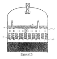
図5は、液体を下部プレートに搬送する手段が少なくとも1つのライン(61)であって、上部プレート(5)を貫通し、その端部(62)および(63)が、端部(62)については下部プレート(21)のレベルに蓄積した液体中に、端部(63)については上部プレートのレベルに蓄積した液体中に浸されるように位置する、ラインを含み得る実施形態を示す。 FIG. 5 shows that the means for transporting the liquid to the lower plate is at least one line (61), which penetrates the upper plate (5), whose ends (62) and (63) are the ends (62). FIG. 6 shows an embodiment that may include lines that are positioned so as to be immersed in the liquid accumulated at the level of the lower plate (21) and immersed in the liquid accumulated at the level of the upper plate for the end (63).
これらのライン(61)(一つのみが示されている)の数および直径は、最少の液体流量のために上部プレート上に最低液体レベルを提供するように計算される。この最低レベルは、ガスが下部プレートの方に搬送されることを防止することを顕著に可能にする。このレベルは、一般的には少なくとも50mm、好ましくは少なくとも100mmである。 The number and diameter of these lines (61) (only one shown) is calculated to provide the lowest liquid level on the upper plate for the lowest liquid flow rate. This minimum level significantly makes it possible to prevent gas from being transported towards the lower plate. This level is generally at least 50 mm, preferably at least 100 mm.
ライン(61)の下端(62)は、一般的に、下部プレート(21)のライザ(22)の一番下の側部オリフィスの下に位置する。この構成において、ライン(61)は、常時、液体により満たされ、上部プレートからの液体は、下部プレートのガスおよび液体の間の界面に影響を及ぼさない。下部プレートの液体レベルの下にそれが直接的に注入されるからである。したがって、この界面は、液体およびガスの流量がどうであれ全体的に平坦なままである。 The lower end (62) of the line (61) is generally located below the bottom side orifice of the riser (22) of the lower plate (21). In this configuration, line (61) is always filled with liquid, and liquid from the upper plate does not affect the interface between the gas and liquid in the lower plate. This is because it is injected directly below the liquid level of the lower plate. Thus, this interface remains generally flat regardless of the liquid and gas flow rates.
(実施例)
以降に与えられる実施例は、標準的な分配プレートに対する、本発明による分配プレートの利点を例示することを可能にする。これらの実施例は、一方で標準タイプの装置(従来技術)および他方で本発明による装置を示すモデルについての実験から達成される。これらのモデルは、600mmの直径の反応器であって、その壁が透明であり、粒子充填層を含むものにおいて用いられた。用いられた流体は、水および空気であった。
(Example)
The examples given below make it possible to illustrate the advantages of the distribution plate according to the invention over standard distribution plates. These examples are achieved from experiments on a model showing on the one hand a standard type device (prior art) and on the other hand a device according to the invention. These models were used in 600 mm diameter reactors whose walls were transparent and included a particle packed bed. The fluids used were water and air.
標準タイプの装置のモデルは、ライザを備えたプレートを含み、該ライザは、プレート上に開口する上部と、プレートの下側と連絡する下端とを有し、ライザの上部には側部オリフィスが設けられる。この装置において、液体は、管状システムによって、反応器の外側から分配プレートに送達され、その結果、前記管状システムの下端は、前記プレート上に蓄積した液体中に浸されたままである。管状システムの下端は、プレートに蓄積した液体中に浸された孔あき管によって引き延ばされる。
A model of a standard type device includes a plate with a riser that has an upper portion that opens onto the plate and a lower end that communicates with the lower side of the plate, with a side orifice at the top of the riser. Provided. In this device, the liquid is by a tube-like system, is delivered from the outside of the reactor to the distributor plate, so that the lower end of the tubular system remains immersed in the liquid accumulated in the plate. The lower end of the tubular system is stretched by a perforated tube immersed in the liquid accumulated in the plate.
本発明による装置のモデルは、図2に示される装置に対応する。上部プレートは、ガス分離および搬送手段(3)を備えており、本発明の場合、それは、端部において開口し、カバーが設けられた管である。上部プレートは、液体搬送手段を備えており、本発明の場合、それは、5mmの直径のオリフィスである。下部プレートは、19〜25mmのライザを備えており、ライザのそれぞれは、3列の側部オリフィスを有する。 The model of the device according to the invention corresponds to the device shown in FIG. The upper plate is provided with gas separation and transport means (3), which in the case of the invention is a tube that is open at the end and provided with a cover. The top plate is provided with liquid conveying means, which in the case of the present invention is a 5 mm diameter orifice. The lower plate is equipped with 19-25 mm risers, each of which has three rows of side orifices.
標準装置モデルの下部プレートのライザの特徴は、本発明による装置のモデルの特徴と同一であり、すなわち、19〜25mmの直径のライザであり、ライザのそれぞれは、3列の側部オリフィスを有している。 The features of the lower plate riser of the standard equipment model are identical to those of the equipment model according to the invention, i.e. a 19-25 mm diameter riser, each of the risers having three rows of side orifices. doing.
両方の場合において、液体流(水)およびガス流(空気)は、それぞれ、10kg/m2/sおよび0.023kg/m2/sにほぼ維持される。 In both cases, the liquid flow (water) and the gas flow (air), respectively, are substantially maintained 10kg / m 2 / s and 0.023kg / m 2 / s.
図6および7は、下部プレートのレベルにおけるガスおよび液体の間の界面を示す写真であり、図6については標準タイプの装置(従来技術)のモデルのもの、図7については本発明による装置のモデルのものである。 6 and 7 are photographs showing the interface between gas and liquid at the level of the lower plate, with FIG. 6 for a model of a standard type device (prior art) and for FIG. 7 of the device according to the invention. Of the model.
標準装置の場合、図6に示されるガスおよび液体の間の界面の変動は、50mm程度である。これらの変動は、ランダムな液体流をライザに生じさせる。これらの変動の高さは、ライザ上の2つの連続するオリフィスの間の距離と同じ程度であり、ライザは、同一数のオリフィスと連動しない。これらの変動は、液体流のアンバランスを伴う。 In the case of a standard apparatus, the fluctuation of the interface between the gas and the liquid shown in FIG. 6 is about 50 mm. These variations produce a random liquid flow in the riser. The height of these variations is on the same order as the distance between two successive orifices on the riser, and the riser does not work with the same number of orifices. These variations are accompanied by an imbalance in the liquid flow.
本発明による装置の場合、図7に示される下部プレート上のガスおよび液体の間の界面の変動は、5mm程度、すなわち、標準システムの10分の1未満である。液体レベルが全ライザから同一の上流にあることが観察され得る。さらに、界面に形成された泡状雲が塔の断面全体にわたって均一に分配されることを考慮して、ガスおよび液体の間の接触は、断面全体にわたって均一であり、注入される液体の流れは、ライザの全てについて同一である。 In the case of the device according to the invention, the variation of the interface between the gas and the liquid on the lower plate shown in FIG. 7 is of the order of 5 mm, ie less than a tenth of the standard system. It can be observed that the liquid level is the same upstream from all risers. Furthermore, considering that the bubble cloud formed at the interface is evenly distributed across the entire cross section of the tower, the contact between the gas and the liquid is uniform throughout the cross section and the injected liquid flow is , The same for all of the risers.
図8aおよび8bは、図8aについては標準タイプの装置(従来技術)から、図8bについては本発明による装置から下流の粒子充填層の断面について測定されるガス濃度の分布を示す。各図下のスケールは、100%液体についての黒色から100%ガスについての白色にわたるガス濃度変動範囲を示している。 FIGS. 8a and 8b show the gas concentration distribution measured from a standard type device (prior art) for FIG. 8a and for the cross section of the particle packed bed downstream from the device according to the invention for FIG. 8b. The scale at the bottom of each figure shows the gas concentration variation range from black for 100% liquid to white for 100% gas.
図8aおよび8bにおいて見られ得るように、ガス濃度の分布は、本発明による装置の場合には断面全体にわたって均一である一方で、ガス欠損を伴う領域が、標準装置から下流の層の断面の中心に観察され得る。 As can be seen in FIGS. 8a and 8b, the distribution of gas concentration is uniform over the entire cross section in the case of the device according to the invention, while the region with gas defects is in the cross section of the layer downstream from the standard device. Can be observed in the center.
標準装置の場合、層の周辺上のガスおよび液体の間の界面の変動は、入口ディフューザからのガス/液体噴流の影響に起因し、これは、塔の周辺上に位置するライザにより偏ったガス供給を生じさせる。本発明者らが、測定されるガス濃度が予想されるガス濃度±10%に等しい画像の画素の百分率として分配効率の基準を規定する場合、分配効率は、標準装置について79%、本発明による装置について96%であり、これは、ガス/液体混合物によって適切に活性にされた床の断面の部分の17%の増幅率に対応する。 In the case of standard equipment, the interface variation between the gas and liquid on the perimeter of the bed is due to the effect of the gas / liquid jet from the inlet diffuser, which is due to the gas biased by the riser located on the perimeter of the tower. Produce a supply. If we define the distribution efficiency criteria as a percentage of image pixels where the measured gas concentration is equal to the expected gas concentration ± 10%, the distribution efficiency is 79% for the standard device, according to the present invention. 96% for the device, which corresponds to an amplification factor of 17% of the section of the bed cross-section appropriately activated by the gas / liquid mixture.
Claims (17)
該送達手段は、実質的に水平な上部プレート(5)を含み、該プレート(5)上にガスおよび液体が供給され、該上部プレートは、液体を下部プレートに搬送する手段と、ガス分離および搬送手段(7)とを備え、該ガス分離および搬送手段(7)は、ガスのみの通過を可能にし、上部プレート(5)は、下部プレート(21)のライザ(22)の上端上に直接的に支持されており、これにより、上部プレート(5)は、ライザ(22)の上端を閉じている、装置。 Gas and liquid delivery means and a substantially horizontal lower plate (21), the lower plate comprising a plurality of risers (22) uniformly distributed on the surface of the plate, each riser An upper portion (23) and a lower end (25) in communication with the lower side of the plate, the upper portion (23) of the riser (22) comprising at least one side orifice (26), An apparatus for mixing and distributing gases and liquids arranged upstream from the particle packed bed (2),
The delivery means comprises a substantially horizontal upper plate (5) on which gas and liquid are supplied, the upper plate comprising means for conveying the liquid to the lower plate, gas separation and Conveying means (7), the gas separating and conveying means (7) allowing only gas to pass, and the upper plate (5) directly on the upper end of the riser (22) of the lower plate (21) Device, whereby the upper plate (5) closes the upper end of the riser (22).
Applications Claiming Priority (3)
| Application Number | Priority Date | Filing Date | Title |
|---|---|---|---|
| FR0502647 | 2005-03-17 | ||
| FR0502647A FR2883200B1 (en) | 2005-03-17 | 2005-03-17 | DEVICE FOR MIXING AND DISTRIBUTING A GAS AND A LIQUID BEFORE A GRANULAR BED |
| PCT/FR2006/000406 WO2006097590A2 (en) | 2005-03-17 | 2006-02-21 | Device for mixing and distributing a gas and a liquid upstream of a granular bed |
Publications (3)
| Publication Number | Publication Date |
|---|---|
| JP2008532755A JP2008532755A (en) | 2008-08-21 |
| JP2008532755A5 JP2008532755A5 (en) | 2012-06-07 |
| JP5473323B2 true JP5473323B2 (en) | 2014-04-16 |
Family
ID=35295378
Family Applications (1)
| Application Number | Title | Priority Date | Filing Date |
|---|---|---|---|
| JP2008501348A Active JP5473323B2 (en) | 2005-03-17 | 2006-02-21 | Apparatus for mixing and distributing gas and liquid upstream from a particle packed bed |
Country Status (8)
| Country | Link |
|---|---|
| US (1) | US7500658B2 (en) |
| EP (1) | EP1866068B1 (en) |
| JP (1) | JP5473323B2 (en) |
| KR (1) | KR101253797B1 (en) |
| CN (1) | CN101142013B (en) |
| ES (1) | ES2446103T3 (en) |
| FR (1) | FR2883200B1 (en) |
| WO (1) | WO2006097590A2 (en) |
Families Citing this family (18)
| Publication number | Priority date | Publication date | Assignee | Title |
|---|---|---|---|---|
| RU2466784C2 (en) * | 2007-06-21 | 2012-11-20 | Басф Се | Reactor for three-phase reaction of liquid and gas phases in static bed of catalyst |
| BRPI0904285B1 (en) * | 2009-10-30 | 2019-09-10 | Petroleo Brasileiro Sa Petrobras | device for cooling and distributing mixed loads on fixed catalyst beds |
| EP2476482B2 (en) | 2011-01-18 | 2020-05-13 | Neste Oyj | Method and arrangement for feeding heat-sensitive materials to fixed-bed reactors |
| FR2978679B1 (en) * | 2011-08-03 | 2014-01-17 | Total Raffinage Marketing | DISPENSER PLATE OF A GAS AND A LIQUID, REACTOR EQUIPPED WITH SUCH A TRAY AND USE OF SAID PLATEAU. |
| FR3016533B1 (en) * | 2014-01-21 | 2016-01-15 | IFP Energies Nouvelles | DISPENSER PLATE FOR EXCHANGE COLUMN BETWEEN GAS AND LIQUID WITH LIQUID DEFLECTOR |
| CN104857895A (en) * | 2014-02-26 | 2015-08-26 | 中国科学院大连化学物理研究所 | Gas-liquid distributor of integral reactor for gas-solid-solid three-phase reaction |
| EP2918332A1 (en) * | 2014-03-14 | 2015-09-16 | Morten Müller Ltd., ApS | Scale collection and predistribution tray for vessel with downwards two-phase flow |
| CN104056579B (en) * | 2014-07-04 | 2016-04-20 | 华东理工大学 | A kind of up-flow reactor gas-liquid partition tray and intersegmental benefit hydrogen production device thereof |
| FR3027530B1 (en) * | 2014-10-27 | 2016-11-18 | Ifp Energies Now | REACTOR COMPRISING A SOLIDARITY GAS / LIQUID DISPENSING AND SEPARATING DEVICE. |
| FR3027531B1 (en) * | 2014-10-27 | 2016-11-18 | Ifp Energies Now | REACTOR COMPRISING A DEVICE FOR DISTRIBUTION AND SEPARATION GAS / LIQUID WITH REDUCED GASEOUS CLOUD |
| FR3030295B1 (en) * | 2014-12-17 | 2018-09-28 | IFP Energies Nouvelles | COMPACT DISPENSER TRAY FOR CONTACT COLUMNS GAS / LIQUID AT SEA |
| KR102608487B1 (en) * | 2015-11-09 | 2023-11-30 | 아이에프피 에너지스 누벨 | Filtration and distribution devices for catalytic reactors |
| FR3051375B1 (en) * | 2016-05-18 | 2018-06-01 | IFP Energies Nouvelles | FILTRATION AND DISTRIBUTION DEVICE FOR CATALYTIC REACTOR. |
| FR3043339B1 (en) * | 2015-11-09 | 2017-12-01 | Ifp Energies Now | FILTRATION AND DISTRIBUTION DEVICE FOR CATALYTIC REACTOR |
| US10441932B2 (en) * | 2017-06-28 | 2019-10-15 | Uop Llc | Apparatus for vapor-liquid distribution |
| US10556212B2 (en) * | 2017-12-21 | 2020-02-11 | Uop Llc | Scale collection device for downflow reactors |
| US11224849B2 (en) * | 2017-12-21 | 2022-01-18 | Uop Llc | Scale collection device for downflow reactors |
| CN113318576A (en) * | 2021-06-15 | 2021-08-31 | 江西省人民医院 | Anesthesia department is with anesthesia waste gas pump drainage device |
Family Cites Families (23)
| Publication number | Priority date | Publication date | Assignee | Title |
|---|---|---|---|---|
| US1790224A (en) * | 1927-04-19 | 1931-01-27 | Julian A Campbell | Collector pan for absorbers |
| US3232590A (en) * | 1964-07-08 | 1966-02-01 | Us Stoneware Co | Treating tower having a plate for collecting, mixing and distributing liquid |
| US3524731A (en) * | 1968-09-30 | 1970-08-18 | Exxon Research Engineering Co | Mixed-phase flow distributor for packed beds |
| US3946104A (en) * | 1973-01-13 | 1976-03-23 | Friedrich Uhde Gmbh | Method of producing an homogeneous gas mixture |
| US4126540A (en) * | 1973-08-03 | 1978-11-21 | Atlantic Richfield Company | Apparatus and process for distributing a mixed phase through solids |
| DE2439144C3 (en) * | 1974-08-14 | 1979-04-05 | Siemens Ag, 1000 Berlin Und 8000 Muenchen | Device for distributing flowing media from a flow cross-section to a different flow cross-section |
| US4126539A (en) * | 1977-12-05 | 1978-11-21 | Mobil Oil Corporation | Method and arrangement of apparatus for hydrogenating hydrocarbons |
| US4140625A (en) * | 1977-12-19 | 1979-02-20 | Uop Inc. | Mixed-phase distributor for fixed-bed catalytic reaction chambers |
| US4836989A (en) * | 1987-07-02 | 1989-06-06 | Mobil Oil Corporation | Distribution system for downflow reactors |
| JPH02176293A (en) * | 1988-12-27 | 1990-07-09 | Shiro Kanao | Pressureproof helical corrugated pipe and manufacture thereof |
| US5403561A (en) * | 1993-08-27 | 1995-04-04 | Exxon Research & Engineering Co. | Mixed phase fixed bed reactor distributor |
| US5484578A (en) * | 1994-06-20 | 1996-01-16 | Mobil Oil Corporation | Two-phase distributor system for downflow reactors |
| US5635145A (en) * | 1994-08-23 | 1997-06-03 | Shell Oil Company | Multi-bed downflow reactor |
| FR2745202B1 (en) * | 1996-02-27 | 1998-04-30 | Inst Francais Du Petrole | TRAY FOR DISTRIBUTING A POLYPHASIC MIXTURE THROUGH A CATALYTIC BED |
| FR2745201B1 (en) * | 1996-02-27 | 1998-04-24 | Inst Francais Du Petrole | DEVICE FOR DISPENSING A POLYPHASIC MIXTURE THROUGH A CATALYTIC BED |
| FR2807676B1 (en) * | 2000-04-17 | 2002-07-12 | Inst Francais Du Petrole | POLYFUNCTIONAL SUB-ASSEMBLY PROVIDING CONTACT, DISTRIBUTION OF MATERIAL AND EXCHANGE OF HEAT AND / OR MATERIAL OF AT LEAST ONE GASEOUS PHASE AND AT LEAST ONE LIQUID PHASE |
| FR2813023B1 (en) * | 2000-08-17 | 2003-10-24 | Inst Francais Du Petrole | DISPENSING DEVICE FOR MAKING A POLYPHASIC MIXTURE AND RELATED REACTOR |
| FR2813024B1 (en) * | 2000-08-17 | 2004-02-13 | Inst Francais Du Petrole | DEVICE FOR INJECTING A FLUID PLACED BETWEEN TWO SUCCESSIVE BEDS FOR SIMULTANEOUSLY MAKING AND DISPENSING A POLYPHASIC MIXTURE |
| FR2832075B1 (en) * | 2001-11-09 | 2005-02-04 | Inst Francais Du Petrole | DEVICE FOR DISPENSING A POLYPHASIC MIXTURE ON A BED OF GRANULAR SOLID COMPRISING A BROKEN POROUS REJECTION ELEMENT |
| FR2842435B1 (en) * | 2002-07-16 | 2004-09-24 | Inst Francais Du Petrole | DEVICE FOR MIXING AND DISPENSING A DENSE FLUID AND A LIGHT FLUID PLACED UPSTREAM OF A GRANULAR BED AND ITS USE IN DOWNFLOW |
| US7045103B2 (en) * | 2003-01-13 | 2006-05-16 | Exxonmobil Research And Engineering Company | Multiphase mixing device with baffles |
| FR2853260B1 (en) * | 2003-04-02 | 2005-05-06 | Inst Francais Du Petrole | IMPROVED DEVICE FOR MIXING AND DISPENSING A GAS PHASE AND A LIQUID PHASE SUPPLYING A GRANULAR BED |
| US7121537B2 (en) * | 2003-07-10 | 2006-10-17 | Institut Francais Du Petrole | Enclosed space for mixing and distribution of a gaseous phase and a liquid phase circulating in ascending flow |
-
2005
- 2005-03-17 FR FR0502647A patent/FR2883200B1/en active Active
-
2006
- 2006-02-21 EP EP06709366.6A patent/EP1866068B1/en active Active
- 2006-02-21 JP JP2008501348A patent/JP5473323B2/en active Active
- 2006-02-21 KR KR1020077023615A patent/KR101253797B1/en active IP Right Grant
- 2006-02-21 CN CN2006800082185A patent/CN101142013B/en active Active
- 2006-02-21 WO PCT/FR2006/000406 patent/WO2006097590A2/en not_active Application Discontinuation
- 2006-02-21 ES ES06709366.6T patent/ES2446103T3/en active Active
- 2006-12-15 US US11/639,305 patent/US7500658B2/en active Active
Also Published As
| Publication number | Publication date |
|---|---|
| KR20070120991A (en) | 2007-12-26 |
| US7500658B2 (en) | 2009-03-10 |
| ES2446103T3 (en) | 2014-03-06 |
| WO2006097590A3 (en) | 2007-09-20 |
| WO2006097590A2 (en) | 2006-09-21 |
| FR2883200A1 (en) | 2006-09-22 |
| EP1866068B1 (en) | 2013-12-04 |
| FR2883200B1 (en) | 2007-05-11 |
| EP1866068A2 (en) | 2007-12-19 |
| KR101253797B1 (en) | 2013-04-12 |
| CN101142013A (en) | 2008-03-12 |
| CN101142013B (en) | 2012-11-14 |
| JP2008532755A (en) | 2008-08-21 |
| US20070144352A1 (en) | 2007-06-28 |
Similar Documents
| Publication | Publication Date | Title |
|---|---|---|
| JP5473323B2 (en) | Apparatus for mixing and distributing gas and liquid upstream from a particle packed bed | |
| US8728403B2 (en) | Filtration tray for fixed bed reactor with a co-current down-flow of gas and liquid | |
| JP5663128B2 (en) | Distributor for two-phase descending parallel flow vessel | |
| US7473405B2 (en) | Fluid distribution apparatus for downflow multibed poly-phase catalytic reactor | |
| KR102233330B1 (en) | Fluid distribution device | |
| KR101937431B1 (en) | Apparatus and method for hydroconversion | |
| KR20120093206A (en) | Flow distribution device for downflow catalytic reactors | |
| JP2006341248A (en) | Distributor | |
| JP2008528248A5 (en) | ||
| JP4697572B2 (en) | A dense and light fluid mixing and dispensing device located upstream of the granular bed and use of the device in downflow | |
| JP2000262802A (en) | Apparatus for recovering and distributing liquid in column | |
| JP5389019B2 (en) | Inclusion body containing a granular layer and distribution of gas phase and liquid phase circulating as an upward flow in the inclusion body | |
| JP2004307504A (en) | Device for mixing and distributing gas phase and liquid phase supplied to granular bed | |
| JP2014503348A (en) | Distribution trays, containers or related methods | |
| JPH0677683B2 (en) | Liquid flow distribution device and method | |
| US7029638B2 (en) | Device for separate injection and homogeneous distribution of two fluids | |
| KR101535058B1 (en) | Slurry bubble column reactor | |
| JP4834879B2 (en) | Enclosed space for mixing and distributing the gas and liquid phases circulating in the upward flow | |
| KR20120024490A (en) | Device for distributing a polyphase mixture comprising a jet breaker tray with a separating element |
Legal Events
| Date | Code | Title | Description |
|---|---|---|---|
| A521 | Request for written amendment filed |
Free format text: JAPANESE INTERMEDIATE CODE: A523 Effective date: 20090218 |
|
| A621 | Written request for application examination |
Free format text: JAPANESE INTERMEDIATE CODE: A621 Effective date: 20090218 |
|
| A977 | Report on retrieval |
Free format text: JAPANESE INTERMEDIATE CODE: A971007 Effective date: 20110819 |
|
| A131 | Notification of reasons for refusal |
Free format text: JAPANESE INTERMEDIATE CODE: A131 Effective date: 20111011 |
|
| A601 | Written request for extension of time |
Free format text: JAPANESE INTERMEDIATE CODE: A601 Effective date: 20120110 |
|
| A602 | Written permission of extension of time |
Free format text: JAPANESE INTERMEDIATE CODE: A602 Effective date: 20120117 |
|
| A601 | Written request for extension of time |
Free format text: JAPANESE INTERMEDIATE CODE: A601 Effective date: 20120209 |
|
| A602 | Written permission of extension of time |
Free format text: JAPANESE INTERMEDIATE CODE: A602 Effective date: 20120216 |
|
| A601 | Written request for extension of time |
Free format text: JAPANESE INTERMEDIATE CODE: A601 Effective date: 20120309 |
|
| A602 | Written permission of extension of time |
Free format text: JAPANESE INTERMEDIATE CODE: A602 Effective date: 20120316 |
|
| A524 | Written submission of copy of amendment under article 19 pct |
Free format text: JAPANESE INTERMEDIATE CODE: A524 Effective date: 20120411 |
|
| A02 | Decision of refusal |
Free format text: JAPANESE INTERMEDIATE CODE: A02 Effective date: 20130205 |
|
| A521 | Request for written amendment filed |
Free format text: JAPANESE INTERMEDIATE CODE: A523 Effective date: 20130605 |
|
| A521 | Request for written amendment filed |
Free format text: JAPANESE INTERMEDIATE CODE: A523 Effective date: 20130718 |
|
| A911 | Transfer to examiner for re-examination before appeal (zenchi) |
Free format text: JAPANESE INTERMEDIATE CODE: A911 Effective date: 20130723 |
|
| A131 | Notification of reasons for refusal |
Free format text: JAPANESE INTERMEDIATE CODE: A131 Effective date: 20130903 |
|
| A521 | Request for written amendment filed |
Free format text: JAPANESE INTERMEDIATE CODE: A523 Effective date: 20131202 |
|
| TRDD | Decision of grant or rejection written | ||
| A01 | Written decision to grant a patent or to grant a registration (utility model) |
Free format text: JAPANESE INTERMEDIATE CODE: A01 Effective date: 20140107 |
|
| A61 | First payment of annual fees (during grant procedure) |
Free format text: JAPANESE INTERMEDIATE CODE: A61 Effective date: 20140204 |
|
| R150 | Certificate of patent or registration of utility model |
Free format text: JAPANESE INTERMEDIATE CODE: R150 Ref document number: 5473323 Country of ref document: JP Free format text: JAPANESE INTERMEDIATE CODE: R150 |
|
| R250 | Receipt of annual fees |
Free format text: JAPANESE INTERMEDIATE CODE: R250 |
|
| R250 | Receipt of annual fees |
Free format text: JAPANESE INTERMEDIATE CODE: R250 |
|
| R250 | Receipt of annual fees |
Free format text: JAPANESE INTERMEDIATE CODE: R250 |
|
| R250 | Receipt of annual fees |
Free format text: JAPANESE INTERMEDIATE CODE: R250 |
|
| R250 | Receipt of annual fees |
Free format text: JAPANESE INTERMEDIATE CODE: R250 |
|
| R250 | Receipt of annual fees |
Free format text: JAPANESE INTERMEDIATE CODE: R250 |
|
| R250 | Receipt of annual fees |
Free format text: JAPANESE INTERMEDIATE CODE: R250 |
|
| R250 | Receipt of annual fees |
Free format text: JAPANESE INTERMEDIATE CODE: R250 |