JP5471726B2 - Brake device for vehicle - Google Patents
Brake device for vehicle Download PDFInfo
- Publication number
- JP5471726B2 JP5471726B2 JP2010083347A JP2010083347A JP5471726B2 JP 5471726 B2 JP5471726 B2 JP 5471726B2 JP 2010083347 A JP2010083347 A JP 2010083347A JP 2010083347 A JP2010083347 A JP 2010083347A JP 5471726 B2 JP5471726 B2 JP 5471726B2
- Authority
- JP
- Japan
- Prior art keywords
- brake
- rod
- braking force
- brake pedal
- vehicle
- Prior art date
- Legal status (The legal status is an assumption and is not a legal conclusion. Google has not performed a legal analysis and makes no representation as to the accuracy of the status listed.)
- Expired - Fee Related
Links
- 230000001172 regenerating effect Effects 0.000 claims description 104
- 230000000994 depressogenic effect Effects 0.000 claims description 53
- 239000012530 fluid Substances 0.000 claims description 51
- 238000004891 communication Methods 0.000 claims description 49
- 230000007246 mechanism Effects 0.000 claims description 43
- 238000001514 detection method Methods 0.000 claims description 12
- 230000004044 response Effects 0.000 claims description 4
- 230000001629 suppression Effects 0.000 claims description 4
- 230000008878 coupling Effects 0.000 claims description 3
- 238000010168 coupling process Methods 0.000 claims description 3
- 238000005859 coupling reaction Methods 0.000 claims description 3
- 230000000149 penetrating effect Effects 0.000 claims description 2
- 238000010248 power generation Methods 0.000 claims description 2
- 238000006243 chemical reaction Methods 0.000 description 37
- 230000005540 biological transmission Effects 0.000 description 31
- 230000008929 regeneration Effects 0.000 description 18
- 238000011069 regeneration method Methods 0.000 description 18
- 239000000446 fuel Substances 0.000 description 15
- 230000001105 regulatory effect Effects 0.000 description 10
- 230000009467 reduction Effects 0.000 description 7
- 238000010586 diagram Methods 0.000 description 6
- 230000000694 effects Effects 0.000 description 6
- 230000009191 jumping Effects 0.000 description 6
- 230000001276 controlling effect Effects 0.000 description 5
- 230000006870 function Effects 0.000 description 5
- 230000008859 change Effects 0.000 description 4
- 230000004048 modification Effects 0.000 description 4
- 238000012986 modification Methods 0.000 description 4
- 230000000881 depressing effect Effects 0.000 description 3
- 230000002093 peripheral effect Effects 0.000 description 3
- 230000009471 action Effects 0.000 description 2
- 230000015572 biosynthetic process Effects 0.000 description 2
- 230000000903 blocking effect Effects 0.000 description 2
- 238000005452 bending Methods 0.000 description 1
- 239000011248 coating agent Substances 0.000 description 1
- 238000000576 coating method Methods 0.000 description 1
- 230000007423 decrease Effects 0.000 description 1
- 238000007599 discharging Methods 0.000 description 1
- 239000013013 elastic material Substances 0.000 description 1
- 239000007788 liquid Substances 0.000 description 1
- 239000002184 metal Substances 0.000 description 1
- 238000000034 method Methods 0.000 description 1
- 230000008569 process Effects 0.000 description 1
- 230000001141 propulsive effect Effects 0.000 description 1
- 230000010349 pulsation Effects 0.000 description 1
- 230000035939 shock Effects 0.000 description 1
- 239000007858 starting material Substances 0.000 description 1
- 230000003068 static effect Effects 0.000 description 1
- 238000011144 upstream manufacturing Methods 0.000 description 1
Images


Classifications
-
- B—PERFORMING OPERATIONS; TRANSPORTING
- B60—VEHICLES IN GENERAL
- B60T—VEHICLE BRAKE CONTROL SYSTEMS OR PARTS THEREOF; BRAKE CONTROL SYSTEMS OR PARTS THEREOF, IN GENERAL; ARRANGEMENT OF BRAKING ELEMENTS ON VEHICLES IN GENERAL; PORTABLE DEVICES FOR PREVENTING UNWANTED MOVEMENT OF VEHICLES; VEHICLE MODIFICATIONS TO FACILITATE COOLING OF BRAKES
- B60T13/00—Transmitting braking action from initiating means to ultimate brake actuator with power assistance or drive; Brake systems incorporating such transmitting means, e.g. air-pressure brake systems
- B60T13/10—Transmitting braking action from initiating means to ultimate brake actuator with power assistance or drive; Brake systems incorporating such transmitting means, e.g. air-pressure brake systems with fluid assistance, drive, or release
- B60T13/58—Combined or convertible systems
-
- B—PERFORMING OPERATIONS; TRANSPORTING
- B60—VEHICLES IN GENERAL
- B60K—ARRANGEMENT OR MOUNTING OF PROPULSION UNITS OR OF TRANSMISSIONS IN VEHICLES; ARRANGEMENT OR MOUNTING OF PLURAL DIVERSE PRIME-MOVERS IN VEHICLES; AUXILIARY DRIVES FOR VEHICLES; INSTRUMENTATION OR DASHBOARDS FOR VEHICLES; ARRANGEMENTS IN CONNECTION WITH COOLING, AIR INTAKE, GAS EXHAUST OR FUEL SUPPLY OF PROPULSION UNITS IN VEHICLES
- B60K6/00—Arrangement or mounting of plural diverse prime-movers for mutual or common propulsion, e.g. hybrid propulsion systems comprising electric motors and internal combustion engines ; Control systems therefor, i.e. systems controlling two or more prime movers, or controlling one of these prime movers and any of the transmission, drive or drive units Informative references: mechanical gearings with secondary electric drive F16H3/72; arrangements for handling mechanical energy structurally associated with the dynamo-electric machine H02K7/00; machines comprising structurally interrelated motor and generator parts H02K51/00; dynamo-electric machines not otherwise provided for in H02K see H02K99/00
- B60K6/20—Arrangement or mounting of plural diverse prime-movers for mutual or common propulsion, e.g. hybrid propulsion systems comprising electric motors and internal combustion engines ; Control systems therefor, i.e. systems controlling two or more prime movers, or controlling one of these prime movers and any of the transmission, drive or drive units Informative references: mechanical gearings with secondary electric drive F16H3/72; arrangements for handling mechanical energy structurally associated with the dynamo-electric machine H02K7/00; machines comprising structurally interrelated motor and generator parts H02K51/00; dynamo-electric machines not otherwise provided for in H02K see H02K99/00 the prime-movers consisting of electric motors and internal combustion engines, e.g. HEVs
- B60K6/42—Arrangement or mounting of plural diverse prime-movers for mutual or common propulsion, e.g. hybrid propulsion systems comprising electric motors and internal combustion engines ; Control systems therefor, i.e. systems controlling two or more prime movers, or controlling one of these prime movers and any of the transmission, drive or drive units Informative references: mechanical gearings with secondary electric drive F16H3/72; arrangements for handling mechanical energy structurally associated with the dynamo-electric machine H02K7/00; machines comprising structurally interrelated motor and generator parts H02K51/00; dynamo-electric machines not otherwise provided for in H02K see H02K99/00 the prime-movers consisting of electric motors and internal combustion engines, e.g. HEVs characterised by the architecture of the hybrid electric vehicle
- B60K6/44—Series-parallel type
- B60K6/445—Differential gearing distribution type
-
- B—PERFORMING OPERATIONS; TRANSPORTING
- B60—VEHICLES IN GENERAL
- B60T—VEHICLE BRAKE CONTROL SYSTEMS OR PARTS THEREOF; BRAKE CONTROL SYSTEMS OR PARTS THEREOF, IN GENERAL; ARRANGEMENT OF BRAKING ELEMENTS ON VEHICLES IN GENERAL; PORTABLE DEVICES FOR PREVENTING UNWANTED MOVEMENT OF VEHICLES; VEHICLE MODIFICATIONS TO FACILITATE COOLING OF BRAKES
- B60T1/00—Arrangements of braking elements, i.e. of those parts where braking effect occurs specially for vehicles
- B60T1/02—Arrangements of braking elements, i.e. of those parts where braking effect occurs specially for vehicles acting by retarding wheels
- B60T1/10—Arrangements of braking elements, i.e. of those parts where braking effect occurs specially for vehicles acting by retarding wheels by utilising wheel movement for accumulating energy, e.g. driving air compressors
-
- B—PERFORMING OPERATIONS; TRANSPORTING
- B60—VEHICLES IN GENERAL
- B60T—VEHICLE BRAKE CONTROL SYSTEMS OR PARTS THEREOF; BRAKE CONTROL SYSTEMS OR PARTS THEREOF, IN GENERAL; ARRANGEMENT OF BRAKING ELEMENTS ON VEHICLES IN GENERAL; PORTABLE DEVICES FOR PREVENTING UNWANTED MOVEMENT OF VEHICLES; VEHICLE MODIFICATIONS TO FACILITATE COOLING OF BRAKES
- B60T13/00—Transmitting braking action from initiating means to ultimate brake actuator with power assistance or drive; Brake systems incorporating such transmitting means, e.g. air-pressure brake systems
- B60T13/10—Transmitting braking action from initiating means to ultimate brake actuator with power assistance or drive; Brake systems incorporating such transmitting means, e.g. air-pressure brake systems with fluid assistance, drive, or release
- B60T13/24—Transmitting braking action from initiating means to ultimate brake actuator with power assistance or drive; Brake systems incorporating such transmitting means, e.g. air-pressure brake systems with fluid assistance, drive, or release the fluid being gaseous
- B60T13/46—Vacuum systems
- B60T13/52—Vacuum systems indirect, i.e. vacuum booster units
- B60T13/57—Vacuum systems indirect, i.e. vacuum booster units characterised by constructional features of control valves
-
- B—PERFORMING OPERATIONS; TRANSPORTING
- B60—VEHICLES IN GENERAL
- B60T—VEHICLE BRAKE CONTROL SYSTEMS OR PARTS THEREOF; BRAKE CONTROL SYSTEMS OR PARTS THEREOF, IN GENERAL; ARRANGEMENT OF BRAKING ELEMENTS ON VEHICLES IN GENERAL; PORTABLE DEVICES FOR PREVENTING UNWANTED MOVEMENT OF VEHICLES; VEHICLE MODIFICATIONS TO FACILITATE COOLING OF BRAKES
- B60T13/00—Transmitting braking action from initiating means to ultimate brake actuator with power assistance or drive; Brake systems incorporating such transmitting means, e.g. air-pressure brake systems
- B60T13/10—Transmitting braking action from initiating means to ultimate brake actuator with power assistance or drive; Brake systems incorporating such transmitting means, e.g. air-pressure brake systems with fluid assistance, drive, or release
- B60T13/66—Electrical control in fluid-pressure brake systems
- B60T13/68—Electrical control in fluid-pressure brake systems by electrically-controlled valves
- B60T13/686—Electrical control in fluid-pressure brake systems by electrically-controlled valves in hydraulic systems or parts thereof
-
- B—PERFORMING OPERATIONS; TRANSPORTING
- B60—VEHICLES IN GENERAL
- B60T—VEHICLE BRAKE CONTROL SYSTEMS OR PARTS THEREOF; BRAKE CONTROL SYSTEMS OR PARTS THEREOF, IN GENERAL; ARRANGEMENT OF BRAKING ELEMENTS ON VEHICLES IN GENERAL; PORTABLE DEVICES FOR PREVENTING UNWANTED MOVEMENT OF VEHICLES; VEHICLE MODIFICATIONS TO FACILITATE COOLING OF BRAKES
- B60T7/00—Brake-action initiating means
- B60T7/02—Brake-action initiating means for personal initiation
- B60T7/04—Brake-action initiating means for personal initiation foot actuated
- B60T7/042—Brake-action initiating means for personal initiation foot actuated by electrical means, e.g. using travel or force sensors
-
- B—PERFORMING OPERATIONS; TRANSPORTING
- B60—VEHICLES IN GENERAL
- B60T—VEHICLE BRAKE CONTROL SYSTEMS OR PARTS THEREOF; BRAKE CONTROL SYSTEMS OR PARTS THEREOF, IN GENERAL; ARRANGEMENT OF BRAKING ELEMENTS ON VEHICLES IN GENERAL; PORTABLE DEVICES FOR PREVENTING UNWANTED MOVEMENT OF VEHICLES; VEHICLE MODIFICATIONS TO FACILITATE COOLING OF BRAKES
- B60T7/00—Brake-action initiating means
- B60T7/02—Brake-action initiating means for personal initiation
- B60T7/04—Brake-action initiating means for personal initiation foot actuated
- B60T7/06—Disposition of pedal
-
- B—PERFORMING OPERATIONS; TRANSPORTING
- B60—VEHICLES IN GENERAL
- B60T—VEHICLE BRAKE CONTROL SYSTEMS OR PARTS THEREOF; BRAKE CONTROL SYSTEMS OR PARTS THEREOF, IN GENERAL; ARRANGEMENT OF BRAKING ELEMENTS ON VEHICLES IN GENERAL; PORTABLE DEVICES FOR PREVENTING UNWANTED MOVEMENT OF VEHICLES; VEHICLE MODIFICATIONS TO FACILITATE COOLING OF BRAKES
- B60T8/00—Arrangements for adjusting wheel-braking force to meet varying vehicular or ground-surface conditions, e.g. limiting or varying distribution of braking force
- B60T8/24—Arrangements for adjusting wheel-braking force to meet varying vehicular or ground-surface conditions, e.g. limiting or varying distribution of braking force responsive to vehicle inclination or change of direction, e.g. negotiating bends
- B60T8/248—Trailer sway, e.g. for preventing jackknifing
-
- B—PERFORMING OPERATIONS; TRANSPORTING
- B60—VEHICLES IN GENERAL
- B60T—VEHICLE BRAKE CONTROL SYSTEMS OR PARTS THEREOF; BRAKE CONTROL SYSTEMS OR PARTS THEREOF, IN GENERAL; ARRANGEMENT OF BRAKING ELEMENTS ON VEHICLES IN GENERAL; PORTABLE DEVICES FOR PREVENTING UNWANTED MOVEMENT OF VEHICLES; VEHICLE MODIFICATIONS TO FACILITATE COOLING OF BRAKES
- B60T8/00—Arrangements for adjusting wheel-braking force to meet varying vehicular or ground-surface conditions, e.g. limiting or varying distribution of braking force
- B60T8/32—Arrangements for adjusting wheel-braking force to meet varying vehicular or ground-surface conditions, e.g. limiting or varying distribution of braking force responsive to a speed condition, e.g. acceleration or deceleration
- B60T8/321—Arrangements for adjusting wheel-braking force to meet varying vehicular or ground-surface conditions, e.g. limiting or varying distribution of braking force responsive to a speed condition, e.g. acceleration or deceleration deceleration
- B60T8/3255—Systems in which the braking action is dependent on brake pedal data
- B60T8/3275—Systems with a braking assistant function, i.e. automatic full braking initiation in dependence of brake pedal velocity
-
- B—PERFORMING OPERATIONS; TRANSPORTING
- B60—VEHICLES IN GENERAL
- B60T—VEHICLE BRAKE CONTROL SYSTEMS OR PARTS THEREOF; BRAKE CONTROL SYSTEMS OR PARTS THEREOF, IN GENERAL; ARRANGEMENT OF BRAKING ELEMENTS ON VEHICLES IN GENERAL; PORTABLE DEVICES FOR PREVENTING UNWANTED MOVEMENT OF VEHICLES; VEHICLE MODIFICATIONS TO FACILITATE COOLING OF BRAKES
- B60T8/00—Arrangements for adjusting wheel-braking force to meet varying vehicular or ground-surface conditions, e.g. limiting or varying distribution of braking force
- B60T8/32—Arrangements for adjusting wheel-braking force to meet varying vehicular or ground-surface conditions, e.g. limiting or varying distribution of braking force responsive to a speed condition, e.g. acceleration or deceleration
- B60T8/34—Arrangements for adjusting wheel-braking force to meet varying vehicular or ground-surface conditions, e.g. limiting or varying distribution of braking force responsive to a speed condition, e.g. acceleration or deceleration having a fluid pressure regulator responsive to a speed condition
- B60T8/38—Arrangements for adjusting wheel-braking force to meet varying vehicular or ground-surface conditions, e.g. limiting or varying distribution of braking force responsive to a speed condition, e.g. acceleration or deceleration having a fluid pressure regulator responsive to a speed condition including valve means of the relay or driver controlled type
-
- B—PERFORMING OPERATIONS; TRANSPORTING
- B60—VEHICLES IN GENERAL
- B60T—VEHICLE BRAKE CONTROL SYSTEMS OR PARTS THEREOF; BRAKE CONTROL SYSTEMS OR PARTS THEREOF, IN GENERAL; ARRANGEMENT OF BRAKING ELEMENTS ON VEHICLES IN GENERAL; PORTABLE DEVICES FOR PREVENTING UNWANTED MOVEMENT OF VEHICLES; VEHICLE MODIFICATIONS TO FACILITATE COOLING OF BRAKES
- B60T8/00—Arrangements for adjusting wheel-braking force to meet varying vehicular or ground-surface conditions, e.g. limiting or varying distribution of braking force
- B60T8/32—Arrangements for adjusting wheel-braking force to meet varying vehicular or ground-surface conditions, e.g. limiting or varying distribution of braking force responsive to a speed condition, e.g. acceleration or deceleration
- B60T8/34—Arrangements for adjusting wheel-braking force to meet varying vehicular or ground-surface conditions, e.g. limiting or varying distribution of braking force responsive to a speed condition, e.g. acceleration or deceleration having a fluid pressure regulator responsive to a speed condition
- B60T8/48—Arrangements for adjusting wheel-braking force to meet varying vehicular or ground-surface conditions, e.g. limiting or varying distribution of braking force responsive to a speed condition, e.g. acceleration or deceleration having a fluid pressure regulator responsive to a speed condition connecting the brake actuator to an alternative or additional source of fluid pressure, e.g. traction control systems
- B60T8/4809—Traction control, stability control, using both the wheel brakes and other automatic braking systems
- B60T8/4827—Traction control, stability control, using both the wheel brakes and other automatic braking systems in hydraulic brake systems
- B60T8/4863—Traction control, stability control, using both the wheel brakes and other automatic braking systems in hydraulic brake systems closed systems
- B60T8/4872—Traction control, stability control, using both the wheel brakes and other automatic braking systems in hydraulic brake systems closed systems pump-back systems
-
- B—PERFORMING OPERATIONS; TRANSPORTING
- B60—VEHICLES IN GENERAL
- B60W—CONJOINT CONTROL OF VEHICLE SUB-UNITS OF DIFFERENT TYPE OR DIFFERENT FUNCTION; CONTROL SYSTEMS SPECIALLY ADAPTED FOR HYBRID VEHICLES; ROAD VEHICLE DRIVE CONTROL SYSTEMS FOR PURPOSES NOT RELATED TO THE CONTROL OF A PARTICULAR SUB-UNIT
- B60W10/00—Conjoint control of vehicle sub-units of different type or different function
- B60W10/04—Conjoint control of vehicle sub-units of different type or different function including control of propulsion units
- B60W10/08—Conjoint control of vehicle sub-units of different type or different function including control of propulsion units including control of electric propulsion units, e.g. motors or generators
-
- B—PERFORMING OPERATIONS; TRANSPORTING
- B60—VEHICLES IN GENERAL
- B60W—CONJOINT CONTROL OF VEHICLE SUB-UNITS OF DIFFERENT TYPE OR DIFFERENT FUNCTION; CONTROL SYSTEMS SPECIALLY ADAPTED FOR HYBRID VEHICLES; ROAD VEHICLE DRIVE CONTROL SYSTEMS FOR PURPOSES NOT RELATED TO THE CONTROL OF A PARTICULAR SUB-UNIT
- B60W10/00—Conjoint control of vehicle sub-units of different type or different function
- B60W10/18—Conjoint control of vehicle sub-units of different type or different function including control of braking systems
- B60W10/184—Conjoint control of vehicle sub-units of different type or different function including control of braking systems with wheel brakes
- B60W10/188—Conjoint control of vehicle sub-units of different type or different function including control of braking systems with wheel brakes hydraulic brakes
-
- B—PERFORMING OPERATIONS; TRANSPORTING
- B60—VEHICLES IN GENERAL
- B60W—CONJOINT CONTROL OF VEHICLE SUB-UNITS OF DIFFERENT TYPE OR DIFFERENT FUNCTION; CONTROL SYSTEMS SPECIALLY ADAPTED FOR HYBRID VEHICLES; ROAD VEHICLE DRIVE CONTROL SYSTEMS FOR PURPOSES NOT RELATED TO THE CONTROL OF A PARTICULAR SUB-UNIT
- B60W30/00—Purposes of road vehicle drive control systems not related to the control of a particular sub-unit, e.g. of systems using conjoint control of vehicle sub-units
- B60W30/18—Propelling the vehicle
- B60W30/18009—Propelling the vehicle related to particular drive situations
- B60W30/18109—Braking
- B60W30/18127—Regenerative braking
-
- B—PERFORMING OPERATIONS; TRANSPORTING
- B60—VEHICLES IN GENERAL
- B60T—VEHICLE BRAKE CONTROL SYSTEMS OR PARTS THEREOF; BRAKE CONTROL SYSTEMS OR PARTS THEREOF, IN GENERAL; ARRANGEMENT OF BRAKING ELEMENTS ON VEHICLES IN GENERAL; PORTABLE DEVICES FOR PREVENTING UNWANTED MOVEMENT OF VEHICLES; VEHICLE MODIFICATIONS TO FACILITATE COOLING OF BRAKES
- B60T2201/00—Particular use of vehicle brake systems; Special systems using also the brakes; Special software modules within the brake system controller
- B60T2201/03—Brake assistants
-
- B—PERFORMING OPERATIONS; TRANSPORTING
- B60—VEHICLES IN GENERAL
- B60T—VEHICLE BRAKE CONTROL SYSTEMS OR PARTS THEREOF; BRAKE CONTROL SYSTEMS OR PARTS THEREOF, IN GENERAL; ARRANGEMENT OF BRAKING ELEMENTS ON VEHICLES IN GENERAL; PORTABLE DEVICES FOR PREVENTING UNWANTED MOVEMENT OF VEHICLES; VEHICLE MODIFICATIONS TO FACILITATE COOLING OF BRAKES
- B60T2270/00—Further aspects of brake control systems not otherwise provided for
- B60T2270/60—Regenerative braking
- B60T2270/604—Merging friction therewith; Adjusting their repartition
-
- B—PERFORMING OPERATIONS; TRANSPORTING
- B60—VEHICLES IN GENERAL
- B60W—CONJOINT CONTROL OF VEHICLE SUB-UNITS OF DIFFERENT TYPE OR DIFFERENT FUNCTION; CONTROL SYSTEMS SPECIALLY ADAPTED FOR HYBRID VEHICLES; ROAD VEHICLE DRIVE CONTROL SYSTEMS FOR PURPOSES NOT RELATED TO THE CONTROL OF A PARTICULAR SUB-UNIT
- B60W20/00—Control systems specially adapted for hybrid vehicles
-
- Y—GENERAL TAGGING OF NEW TECHNOLOGICAL DEVELOPMENTS; GENERAL TAGGING OF CROSS-SECTIONAL TECHNOLOGIES SPANNING OVER SEVERAL SECTIONS OF THE IPC; TECHNICAL SUBJECTS COVERED BY FORMER USPC CROSS-REFERENCE ART COLLECTIONS [XRACs] AND DIGESTS
- Y02—TECHNOLOGIES OR APPLICATIONS FOR MITIGATION OR ADAPTATION AGAINST CLIMATE CHANGE
- Y02T—CLIMATE CHANGE MITIGATION TECHNOLOGIES RELATED TO TRANSPORTATION
- Y02T10/00—Road transport of goods or passengers
- Y02T10/60—Other road transportation technologies with climate change mitigation effect
- Y02T10/62—Hybrid vehicles
Landscapes
- Engineering & Computer Science (AREA)
- Transportation (AREA)
- Mechanical Engineering (AREA)
- Chemical & Material Sciences (AREA)
- Combustion & Propulsion (AREA)
- Physics & Mathematics (AREA)
- Fluid Mechanics (AREA)
- Automation & Control Theory (AREA)
- Braking Elements And Transmission Devices (AREA)
- Regulating Braking Force (AREA)
- Braking Systems And Boosters (AREA)
Description
本発明は、ブレーキ操作状態に応じて車両に付与する目標制動力を液圧ブレーキ装置による液圧制動力と回生ブレーキ装置による回生制動力とによって達成する車両用ブレーキ装置に関するものである。 The present invention relates to a vehicle brake device that achieves a target braking force to be applied to a vehicle according to a brake operation state by a hydraulic braking force by a hydraulic brake device and a regenerative braking force by a regenerative brake device.
従来から、車両用ブレーキ装置としては、ブレーキペダルの踏み込みに応じて基礎液圧をマスタシリンダにて発生し、同発生した基礎液圧を当該マスタシリンダと液圧制御弁を介在した油経路によって連結された各車輪のホイールシリンダに直接付与することにより、同各車輪に前記基礎液圧に対応した基礎液圧制動力を発生させる液圧ブレーキ装置と、回生制動力を車輪の何れかに発生させる回生ブレーキ装置と、を備えており、液圧ブレーキ装置と回生ブレーキ装置とを協調動作させて基礎液圧制動力と回生制動力に基づいてブレーキペダルの操作状態に対応した車両制動力を車両に付与する車両用ブレーキ装置は知られている。 Conventionally, as a brake device for a vehicle, a basic hydraulic pressure is generated in a master cylinder in response to depression of a brake pedal, and the generated basic hydraulic pressure is connected to the master cylinder and an oil path through a hydraulic pressure control valve. The hydraulic brake device that generates the basic hydraulic braking force corresponding to the basic hydraulic pressure on each wheel by directly applying the wheel cylinder to each wheel, and the regenerative brake that generates the regenerative braking force on any of the wheels. A brake device, and the hydraulic brake device and the regenerative brake device are cooperatively operated to apply a vehicle braking force corresponding to the operation state of the brake pedal to the vehicle based on the basic hydraulic brake force and the regenerative braking force. Vehicle brake devices are known.
この車両用ブレーキ装置は、ブレーキペダルとマスタシリンダのピストンとの間に両部材を連結するために設けられたいずれかの連結部材に備えられ、連結部材のブレーキペダル側部分である第1ロッドと、連結部材のマスタシリンダ側部分であって第1ロッドの先端部に摺動可能に係合されている先端部を有する第2ロッドと、第1ロッドと第2ロッドの間に介装され両ロッドを離れる方向に付勢する付勢部材とを備え、かつ、ブレーキペダルの踏み込み時に、第1ロッドがブレーキペダルの踏み込み開始状態である踏み込み開始位置から第1ロッドが第2ロッドに当接する当接位置となるまでの間は基礎液圧制動力の発生を制限し、第1ロッドが当接位置を越えた場合に基礎液圧制動力の発生の制限を解除する基礎液圧制動力発生制限手段を備えている。 The vehicle brake device includes a first rod that is provided on one of the connecting members provided to connect both members between the brake pedal and the piston of the master cylinder, and is a brake pedal side portion of the connecting member; A second rod having a distal end portion slidably engaged with a distal end portion of the first rod, which is a master cylinder side portion of the connecting member, and both interposed between the first rod and the second rod. An urging member that urges the rod away from the rod, and when the brake pedal is depressed, the first rod comes into contact with the second rod from the depression start position where the brake pedal is depressed. Until the contact position is reached, the generation of the basic hydraulic braking force is limited, and when the first rod exceeds the contact position, the basic hydraulic braking force generation limit is released. It is equipped with a.
車両用ブレーキ装置は、当接位置は、回生ブレーキ装置が発生可能な最大回生制動力に基づいて設けられるとともに、第1ロッドが踏み込み開始位置と当接位置との間に位置する場合は、回生ブレーキ装置が発生させる回生制動力のみによりブレーキペダルの操作状態に対応した車両制動力を前記車両に付与し、第1ロッドが当接位置を越えた位置に位置する場合は、液圧ブレーキ装置が発生させる基礎液圧制動力と回生ブレーキ装置が発生させる回生制動力とによりブレーキペダルの操作状態に対応した車両制動力を車両に付与するようになっている。 In the vehicular brake device, the contact position is provided based on the maximum regenerative braking force that can be generated by the regenerative brake device, and when the first rod is located between the stepping start position and the contact position, When the vehicle braking force corresponding to the operation state of the brake pedal is applied to the vehicle only by the regenerative braking force generated by the brake device, and the first rod is positioned beyond the contact position, the hydraulic brake device is A vehicle braking force corresponding to the operation state of the brake pedal is applied to the vehicle by the basic hydraulic braking force generated and the regenerative braking force generated by the regenerative braking device.
上記特許文献1に記載された車両用ブレーキ装置において、ブレーキペダルが急踏みでない非急踏み時においては(例えば通常の踏みこみ速度で踏み込む場合)、回生制動力を積極的に利用することにより、高回生効率、すなわち高燃費を達成することができる。しかし、ブレーキペダルの急踏み時においては、高回生効率・高燃費の達成より基礎液圧制動力をできるだけ早期に付与したいという要請がある。
In the vehicle brake device described in
本発明は、上述した問題を解消するためになされたもので、車両用ブレーキ装置において、ブレーキペダルが非急踏みされた場合に回生制動力を積極的に利用することにより、高回生効率、高燃費を達成するとともに、ブレーキペダルが急踏みされた場合に基礎液圧制動力をできるだけ早期に付与することの両立を図ることを目的とする。 The present invention has been made to solve the above-described problems. In the vehicle brake device, the regenerative braking force is positively used when the brake pedal is not suddenly depressed, thereby achieving high regenerative efficiency, high An object is to achieve both fuel efficiency and the application of the basic hydraulic braking force as early as possible when the brake pedal is stepped on suddenly.
上記の課題を解決するため、請求項1に係る発明の構成上の特徴は、ブレーキペダルの踏み込みに応じて基礎液圧をマスタシリンダにて発生し、同発生した基礎液圧を当該マスタシリンダと液圧制御弁を介在した油経路によって連結された各車輪のホイールシリンダに直接付与することにより、同各車輪に基礎液圧に対応した基礎液圧制動力を発生させる液圧ブレーキ装置と、回生制動力を車輪の何れかに発生させる回生ブレーキ装置と、を備えており、液圧ブレーキ装置と回生ブレーキ装置とを協調動作させて基礎液圧制動力と回生制動力に基づいてブレーキペダルの操作状態に対応した車両制動力を車両に付与する車両用ブレーキ装置において、ブレーキペダルに接続されている第1ロッドと、マスタシリンダに接続されるとともに第1ロッドの先端部との間に空気で満たされる唯一の内部空間を形成しつつ同内部空間の容積を変化させながら第1ロッドの先端部に摺動可能に係合されている第2ロッドと、第1ロッドと第2ロッドの間に介装され両ロッドを内部空間の容積が増大する方向に付勢する付勢部材とを有し、ブレーキペダルとマスタシリンダのピストンとを連動可能に連結する連結機構と、内部空間の内外を連通させ、ブレーキペダルの急踏み時には内部空間からの空気の流出が制限され、非急踏み時には内部空間からの空気の流出が制限されないように設けられた連通路と、を備え、第2ロッドが第1ロッドに摺動している状態では、基礎液圧制動力の発生が抑制され、第2ロッドが第1ロッドと共に移動している状態では、基礎液圧制動力の発生の抑制が解除されるように構成されていることである。
In order to solve the above-mentioned problem, the structural feature of the invention according to
請求項2に係る発明の構成上の特徴は、請求項1において、連通路はオリフィスであることである。
The structural feature of the invention according to
請求項3に係る発明の構成上の特徴は、請求項2において、オリフィスは、第1ロッドと第2ロッドとの隙間であることである。
The structural feature of the invention according to claim 3 is that, in
請求項4に係る発明の構成上の特徴は、請求項1において、第1ロッドの先端部および第2ロッドの先端部の少なくともいずれか一方は先端に開口した有底筒状の筒部を有し、他方は筒部内を摺動し、内部空間は筒部の内側に形成されていることである。
The structural feature of the invention according to claim 4 is that, in
請求項5に係る発明の構成上の特徴は、請求項4において、連通路は、筒部の側壁を貫通するオリフィスであることである。 The structural feature of the invention according to claim 5 is that, in claim 4, the communication path is an orifice penetrating the side wall of the cylindrical portion.
請求項6に係る発明の構成上の特徴は、請求項4または請求項5において、ブレーキペダルの非急踏み時には、ブレーキペダルの踏み込みが開始されてから筒部内の先端部が当該筒部の底に当接するまでの期間中、第2ロッドが第1ロッドに摺動して、基礎液圧制動力の発生が制限され、一方、ブレーキペダルの急踏み時には、ブレーキペダルの踏み込みが開始されてから筒部内の先端部が当該筒部の底に当接する前に、第1ロッドが内部空間内で圧縮された空気を介して第2ロッドを押圧して、基礎液圧制動力の発生の制限が解除されることである。 The structural feature of the invention according to claim 6 is that, according to claim 4 or claim 5, when the brake pedal is not suddenly depressed, the tip of the cylinder portion starts from the start of depression of the brake pedal, and the bottom of the cylinder portion is The second rod slides on the first rod during the period until it comes into contact with the first rod, and the generation of the basic hydraulic braking force is limited. On the other hand, when the brake pedal is suddenly depressed, The first rod presses the second rod through the compressed air in the internal space before the tip of the inner portion comes into contact with the bottom of the cylindrical portion, and the restriction on the generation of the basic hydraulic braking force is released. Is Rukoto.
請求項7に係る発明の構成上の特徴は、請求項4乃至請求項6の何れか一項において、筒部内の先端部が当該筒部の底に当接するブレーキペダルの踏み込み位置は、回生ブレーキ装置が発生可能な最大回生制動力に基づいて設定されていることである。 The structural feature of the invention according to claim 7 is that in any one of claims 4 to 6, the stepping position of the brake pedal where the tip end portion in the cylinder portion abuts on the bottom of the cylinder portion is the regenerative brake. It is set based on the maximum regenerative braking force that can be generated by the device.
請求項8に係る発明の構成上の特徴は、請求項1において、連通路に接続されている流体通路を開放または遮断する制御弁と、ブレーキペダルの急踏みを検出する検出手段と、を備え、検出手段により急踏みが検出されている場合に、制御弁により連通路を遮断させ、検出手段により急踏みが検出されていない場合に、制御弁により連通路を開放させることである。
The structural feature of the invention according to claim 8 is the structure according to
請求項9に係る発明の構成上の特徴は、請求項1乃至請求項8の何れか一項において、車両用ブレーキ装置はブレーキアシスト装置を備え、ブレーキアシスト装置は、ブレーキペダルの急踏み時には、第2ロッドが第1ロッドと共に移動している状態で作動することである。
The structural feature of the invention according to claim 9 is that, in any one of
上記のように構成した請求項1に係る発明においては、上記のように構成した請求項1に係る発明においては、ブレーキペダルの非急踏み時において、ブレーキペダルに接続されている第1ロッドとこの第1ロッドに摺動可能に係合される第2ロッドとの間に形成された内部空間からの空気の流出が、連通路により制限されない。このとき、内部空間の容積は小さくなるが、内部空間内の空気はほとんど圧縮されないため、第2ロッドが第1ロッドに摺動している状態にあり、この状態では基礎液圧制動力の発生が抑制される。これにより、運転者がブレーキペダルを非急踏みした場合、基礎液圧制動力が所定値以下に強制的に制限される。また、この間はブレーキ操作状態に対応した車両制動力を達成するための液圧ブレーキ装置との協調動作によって、回生ブレーキ装置が車両制動力に対する基礎液圧制動力の不足分を回生制動力によって補う。したがって、ブレーキペダルの非急踏み時においては、回生制動力を積極的に利用することになり、高回生効率、すなわち高燃費を達成することができる。
In the invention according to
一方、ブレーキペダルの急踏み時において、内部空間からの空気の流出が連通路により制限される。このとき、例えば内部空間内に圧縮空気が形成されることで、第1ロッドは圧縮空気を介して第2ロッドを押圧するため、第2ロッドが第1ロッドと共に移動している状態にあるため、この状態では基礎液圧制動力の発生の抑制が解除される。これにより、運転者がブレーキペダルを急踏みした場合、基礎液圧制動力を積極的に発生させることができる。なお、この間はブレーキ操作状態に対応した車両制動力を達成するための液圧ブレーキ装置との協調動作によって、回生ブレーキ装置が前記車両制動力に対する基礎液圧制動力の不足分を回生制動力によって補う。したがって、ブレーキペダルの急踏み時には、高回生効率・高燃費より優先して基礎液圧制動力の早期付与を図ることができる。 On the other hand, when the brake pedal is suddenly depressed, the outflow of air from the internal space is restricted by the communication path. At this time, for example, because the compressed air is formed in the internal space, the first rod presses the second rod via the compressed air, and therefore, the second rod is moving together with the first rod. In this state, the suppression of the generation of the basic hydraulic braking force is released. Thereby, when the driver steps on the brake pedal suddenly, the basic hydraulic braking force can be positively generated. During this time, the regenerative braking device compensates for the shortage of the basic hydraulic braking force with respect to the vehicle braking force by the regenerative braking force by the cooperative operation with the hydraulic braking device for achieving the vehicle braking force corresponding to the brake operation state. . Therefore, when the brake pedal is suddenly depressed, the basic hydraulic braking force can be applied at an early stage in preference to high regeneration efficiency and high fuel efficiency.
以上のように、車両用ブレーキ装置において、非急踏み時では回生制動力を積極的に利用することにより、高回生効率、高燃費を達成するとともに、急踏み時には基礎液圧制動力をできるだけ早期に付与することの両立を図ることができる。 As described above, in a vehicle brake system, high regenerative efficiency and high fuel efficiency are achieved by positively using regenerative braking force during non-rapid stepping, and basic hydraulic braking force is applied as early as possible during sudden stepping. It is possible to achieve both.
上記のように構成した請求項2に係る発明においては、請求項1において、連通路はオリフィスである。よって、簡単な構成で内部空間からの空気の流出を絞ることができる。
In the invention according to
上記のように構成した請求項3に係る発明においては、請求項2において、オリフィスは、第1ロッドと第2ロッドとの隙間である。よって、簡便な構成かつ低コストにて内部空間からの空気の流出を絞ることができる。
In the invention which concerns on Claim 3 comprised as mentioned above, in
上記のように構成した請求項4に係る発明においては、請求項1において、第1ロッドの先端部および第2ロッドの先端部の少なくともいずれか一方は先端に開口した有底筒状の筒部を有し、他方は筒部内を摺動し、内部空間は筒部の内側に形成されている。これにより、ブレーキペダルの急踏み時において内部空間内に圧縮空気を形成することを、容易かつ簡単な構成で達成することができる。
In the invention which concerns on Claim 4 comprised as mentioned above, in
上記のように構成した請求項5に係る発明においては、請求項4において、連通路は、筒部の側壁を貫通するオリフィスである。これにより、比較的加工しやすく、流路断面積を精度よくオリフィスを形成することができる。また、外側筒部(または内側筒部)に形成された連通路の入出口が内側筒部(または外側筒部)により塞がれる前は、内部空間内の空気は連通路を介して外部に流出する。さらに、外側筒部(または内側筒部)に形成された連通路の入出口が内側筒部(または外側筒部)によりふさがれた後は、内部空間内の空気が外部に流出しないので、内部空間のダンパー効果をより向上させ、第1ロッドが第2ロッドに当接する際のショック(衝撃)を抑制することができる。 In the invention which concerns on Claim 5 comprised as mentioned above, in Claim 4, a communicating path is an orifice which penetrates the side wall of a cylinder part. Thereby, it is comparatively easy to process, and an orifice can be formed with high accuracy in the cross-sectional area of the flow path. In addition, before the entrance / exit of the communication path formed in the outer cylinder part (or inner cylinder part) is blocked by the inner cylinder part (or outer cylinder part), the air in the internal space is exposed to the outside via the communication path. leak. Furthermore, after the entrance / exit of the communication path formed in the outer cylinder part (or inner cylinder part) is blocked by the inner cylinder part (or outer cylinder part), the air in the inner space does not flow out to the outside. The damper effect of the space can be further improved, and a shock (impact) when the first rod comes into contact with the second rod can be suppressed.
上記のように構成した請求項6に係る発明においては、請求項4または請求項5において、ブレーキペダルの非急踏み時には、ブレーキペダルの踏み込みが開始されてから筒部内の先端部が当該筒部の底に当接するまでの期間中、第2ロッドが第1ロッドに摺動して、基礎液圧制動力の発生が制限され、一方、ブレーキペダルの急踏み時には、ブレーキペダルの踏み込みが開始されてから筒部内の先端部が当該筒部の底に当接する前に、第1ロッドが内部空間内で圧縮された空気を介して第2ロッドを押圧して、基礎液圧制動力の発生の制限が解除される。したがって、ブレーキペダルの踏み込みが開始されてから筒部内の先端部が当該筒部の底に当接するまでの期間中すなわち低踏力領域において、ブレーキペダルの非急踏み時には、回生制動力を積極的に利用することになり、高回生効率、すなわち高燃費を達成することができる。一方、ブレーキペダルの急踏み時には、高回生効率・高燃費より優先して基礎液圧制動力の早期付与を図ることができる。
In the invention according to claim 6 configured as described above, in claim 4 or claim 5, when the brake pedal is not pressed suddenly, the tip of the cylinder portion starts from the start of depression of the brake pedal. The second rod slides on the first rod during the period until it comes into contact with the bottom of the base, and the generation of the basic hydraulic braking force is limited. On the other hand, when the brake pedal is suddenly depressed, the depression of the brake pedal is started. The first rod presses the second rod through the air compressed in the internal space before the tip end in the cylinder portion comes into contact with the bottom of the cylinder portion, so that the generation of the basic hydraulic braking force is restricted. Canceled. Therefore, the regenerative braking force is positively applied when the brake pedal is not suddenly depressed during the period from the start of the depression of the brake pedal to the time when the tip of the cylinder part comes into contact with the bottom of the cylinder part, that is, in the low pedaling force region. Therefore, high regeneration efficiency, that is, high fuel efficiency can be achieved. On the other hand, when the brake pedal is suddenly depressed, the basic hydraulic braking force can be applied at an early stage in preference to high regenerative efficiency and high fuel efficiency.
上記のように構成した請求項7に係る発明においては、請求項4乃至請求項6の何れか一項において、筒部内の先端部が当該筒部の底に当接するブレーキペダルの踏み込み位置は、回生ブレーキ装置が発生可能な最大回生制動力に基づいて設定されている。これにより、ブレーキペダルの非急踏み時において、ブレーキペダルストロークが当接位置を越えた位置に位置する場合は、液圧ブレーキ装置が発生させる基礎液圧制動力と回生ブレーキ装置が発生させる最大回生制動力とによりブレーキペダルの操作状態に対応した車両制動力を車両に付与することができ、高回生効率を実現することができる。 In the invention according to Claim 7 configured as described above, in any one of Claims 4 to 6, the depression position of the brake pedal in which the tip portion in the cylinder portion abuts the bottom of the cylinder portion is It is set based on the maximum regenerative braking force that can be generated by the regenerative braking device. As a result, when the brake pedal stroke is positioned beyond the contact position when the brake pedal is not suddenly depressed, the basic hydraulic braking force generated by the hydraulic brake device and the maximum regenerative braking generated by the regenerative brake device are achieved. A vehicle braking force corresponding to the operation state of the brake pedal can be applied to the vehicle by the power, and high regeneration efficiency can be realized.
上記のように構成した請求項8に係る発明においては、請求項1において、連通路に接続されている流体通路を開放または遮断する制御弁と、ブレーキペダルの急踏みを検出する検出手段と、を備え、検出手段により急踏みが検出されている場合に、制御弁により連通路を遮断させ、検出手段により急踏みが検出されていない場合に、制御弁により連通路を開放させる。これにより、ブレーキペダルの急踏み時/非急踏み時に応じて連通路を確実に遮断/開放することができる。
In the invention according to claim 8 configured as described above, in
上記のように構成した請求項9に係る発明においては、請求項1乃至請求項8の何れか一項において、車両用ブレーキ装置はブレーキアシスト装置を備え、ブレーキアシスト装置は、ブレーキペダルの急踏み時には、第2ロッドが第1ロッドと共に移動している状態で作動する。これにより、ブレーキペダルの急踏み時には、ブレーキアシスト装置により基礎液圧制動力の早期付与を確実に図ることができる。
In the invention according to Claim 9 configured as described above, in any one of
1)第1の実施の形態
以下、本発明に係る車両用ブレーキ装置をハイブリッド車に適用した第1の実施の形態を図面を参照して説明する。図1はそのハイブリッド車の構成を示す概要図であり、図2は車両用ブレーキ装置の基礎液圧制動力発生装置の構成を示す概要図である。ハイブリッド車は、図1に示すように、ハイブリッドシステムによって駆動輪例えば左右前輪FL,FRを駆動させる車両である。ハイブリッドシステムは、エンジン11およびモータ12の2種類の動力源を組み合わせて使用するパワートレーンである。本第1の実施の形態の場合、エンジン11およびモータ12の双方で車輪を直接駆動する方式であるパラレルハイブリッドシステムである。なお、これ以外にシリアルハイブリッドシステムがあるが、これはモータ12によって車輪が駆動され、エンジン11はモータ12への電力供給源として作用する。
1) First Embodiment Hereinafter, a first embodiment in which a vehicle brake device according to the present invention is applied to a hybrid vehicle will be described with reference to the drawings. FIG. 1 is a schematic diagram showing a configuration of the hybrid vehicle, and FIG. 2 is a schematic diagram showing a configuration of a basic hydraulic braking force generating device of a vehicle brake device. As shown in FIG. 1, the hybrid vehicle is a vehicle that drives driving wheels, for example, left and right front wheels FL, FR, by a hybrid system. The hybrid system is a power train that uses a combination of two types of power sources, the
このパラレルハイブリッドシステムを搭載したハイブリッド車は、エンジン11およびモータ12を備えている。エンジン11の駆動力は、動力分割機構13および動力伝達機構14を介して駆動輪(本第1の実施の形態では左右前輪FL,FR)に伝達されるようになっており、モータ12の駆動力は、動力伝達機構14を介して駆動輪に伝達されるようになっている。動力分割機構13は、エンジン11の駆動力を車両駆動力と発電機駆動力に適切に分割するものである。動力伝達機構14は、走行条件に応じてエンジン11およびモータ12の駆動力を適切に統合して駆動輪に伝達するものである。動力伝達機構14はエンジン11とモータ12の伝達される駆動力比を0:100〜100:0の間で調整している。この動力伝達機構14は変速機能を有している。
A hybrid vehicle equipped with this parallel hybrid system includes an
モータ12は、エンジン11の出力を補助し駆動力を高めるものであり、一方車両の制動時には発電を行いバッテリ17を充電するものである。発電機15は、エンジン11の出力により発電を行うものであり、エンジン始動時のスタータの機能を有する。これらモータ12および発電機15は、インバータ16にそれぞれ電気的に接続されている。インバータ16は、直流電源としてのバッテリ17に電気的に接続されており、モータ12および発電機15から入力した交流電圧を直流電圧に変換してバッテリ17に供給したり、逆にバッテリ17からの直流電圧を交流電圧に変換してモータ12および発電機15へ出力したりするものである。
The
本第1の実施の形態においては、これらモータ12、インバータ16およびバッテリ17から回生ブレーキ装置Aが構成されており、この回生ブレーキ装置Aは、ペダルストロークセンサ21a(または圧力センサP)によって検出されたブレーキ操作状態(後述する)に基づいた回生制動力を各車輪FL,FR,RL,RRの何れか(本第1の実施の形態では駆動源であるモータ12によって駆動される左右前輪FL,FR)に発生させるものである。
In the first embodiment, the regenerative brake device A is constituted by the
エンジン11はエンジンECU(電子制御ユニット)18によって制御されており、エンジンECU18は後述するハイブリッドECU(電子制御ユニット)19からのエンジン出力要求値に従って電子制御スロットルに開度指令を出力し、エンジン11の回転数を調整する。ハイブリッドECU19は、インバータ16が互いに通信可能に接続されている。ハイブリッドECU19は、アクセル開度およびシフトポジション(図示しないシフトポジションセンサから入力したシフト位置信号から算出する)から必要なエンジン出力、電気モータトルクおよび発電機トルクを導出し、その導出したエンジン出力要求値をエンジンECU18に送信してエンジン11の駆動力を制御し、また導出した電気モータトルク要求値および発電機トルク要求値に従って、インバータ16を通してモータ12および発電機15を制御する。また、ハイブリッドECU19はバッテリ17が接続されており、バッテリ17の充電状態、充電電流などを監視している。さらに、ハイブリッドECU19は、アクセルペダル(図示省略)に組み付けられて車両のアクセル開度を検出するアクセル開度センサ(図示省略)も接続されており、アクセル開度センサからアクセル開度信号を入力している。
The
また、ハイブリッド車は、直接各車輪FL,FR,RL,RRに液圧制動力を付与して車両を制動させる液圧ブレーキ装置Bを備えている。液圧ブレーキ装置Bは、図4に示すように、ブレーキペダル21の踏み込みによるブレーキ操作状態に対応した基礎液圧をマスタシリンダ23にて発生し、同発生した基礎液圧を当該マスタシリンダ23と液圧制御弁31,41をそれぞれ介在した油経路Lf,Lrによって連結された各車輪FL,FR,RL,RRのホイールシリンダWC1,WC2,WC3,WC4に直接付与することにより、同各車輪FL,FR,RL,RRに基礎液圧に対応した基礎液圧制動力を発生させるとともに、ブレーキ操作状態に対応して発生される基礎液圧とは独立してポンプ37,47の駆動と液圧制御弁31,41の制御によって形成される制御液圧を各車輪FL,FR,RL,RRのホイールシリンダWC1,WC2,WC3,WC4に付与することにより各車輪FL,FR,RL,RRに制御液圧制動力を発生可能に構成されたものである。
The hybrid vehicle also includes a hydraulic brake device B that directly applies a hydraulic braking force to each wheel FL, FR, RL, RR to brake the vehicle. As shown in FIG. 4, the hydraulic brake device B generates a basic hydraulic pressure corresponding to a brake operation state caused by depression of the
この液圧ブレーキ装置Bは、エンジン11の吸気負圧をダイヤフラムに作用させてブレーキペダル21の踏み込み操作により生じるブレーキ操作力を助勢して倍力(増大)する倍力装置である負圧式ブースタ22と、負圧式ブースタ22により倍力されたブレーキ操作力(すなわちブレーキペダル21の操作状態)に応じた基礎液圧である液圧(油圧)のブレーキ液(油)を生成してホイールシリンダWC1〜WC4に供給するマスタシリンダ23と、ブレーキ液を貯蔵してマスタシリンダ23にそのブレーキ液を補給するリザーバタンク24と、マスタシリンダ23とホイールシリンダWC1〜WC4との間に設けられて制御液圧を形成するブレーキアクチュエータ(制御液圧制動力発生装置)25を備えている。なお、ブレーキペダル21、負圧式ブースタ22、マスタシリンダ23、リザーバタンク24によって基礎液圧制動力発生装置が構成されている。
This hydraulic brake device B is a
図2に示すように、ブレーキペダル21はオペレーティングロッド26を介して負圧式ブースタ22に接続され、負圧式ブースタ22はプッシュロッド27を介してマスタシリンダ23に接続されており、ブレーキペダル21に作用されたブレーキ操作力はオペレーティングロッド26を介して負圧式ブースタ22に入力され、倍力されてプッシュロッド27を介してマスタシリンダ23に入力されるようになっている。
As shown in FIG. 2, the
ブレーキペダル21は、ブレーキペダル21の踏み込みによるブレーキ操作状態であるブレーキペダルストロークを検出するペダルストロークセンサ21aが設けられている。このペダルストロークセンサ21aはブレーキECU60に接続されており、検出信号がブレーキECU60に送信されるようになっている。さらに、ブレーキペダル21は、ブレーキ操作状態が所定状態(後述する)となるまでのブレーキペダル21のペダル反力を形成するペダル反力形成手段である反力用スプリング21bが備えられている。反力用スプリング21bは、一端が車両の車体に固定されたブラケット10aに接続されたものであり、ブレーキペダル21を踏み込み方向に対して逆方向である踏み込み解除方向(ブレーキペダル21が踏み込み前の元の位置に戻る方向)に付勢するようになっている。この反力用スプリング21bの付勢力は、マスタシリンダ23のハウジング23aの内径、倍力比などを考慮して設定されるのが望ましい。
The
負圧式ブースタ22は、一般によく知られているものであり、負圧取入れ口22aがエンジン11の吸気マニホールドに連通しており、この吸気マニホールドの負圧を倍力源としている。
The
マスタシリンダ23は、図2に示すように、タンデム式のマスタシリンダであり、有底筒状に形成されたハウジング23aと、ハウジング23a内を液密かつ摺動可能に並べて収納された第1および第2ピストン23b,23cと、第1ピストン23bと第2ピストン23cとの間に形成される第1液圧室23d内に配設された第1スプリング23eと、第2ピストン23cとハウジング23aの閉塞端との間に形成される第2液圧室23f内に配設された第2スプリング23gとから構成されている。これにより、第2ピストン23cは第2スプリング23gによって開口端側(第1ピストン23b側)に付勢され、第1ピストン23bは第1スプリング23eによって開口端側に付勢されて、第1ピストン23bの一端(開口端側端)がプッシュロッド27の先端に押圧されて当接するようになっている。
As shown in FIG. 2, the
マスタシリンダ23のハウジング23aは、第1液圧室23dとリザーバタンク24とを連通するための第1ポート23hと、第2液圧室23fとリザーバタンク24とを連通するための第2ポート23iとが設けられている。第1ポート23hは、ブレーキペダル21から運転者の足が離れている状態すなわちブレーキペダル21が踏み込まれていない状態である第1位置(戻り位置:図2の図示状態)にある第1ピストン23bの同ポート23hを閉塞する閉塞端が第1ポート23hの開口端に一致する位置(すなわち第1ピストン23bの閉塞端が第1ポート23hの開口を塞ぎ始める直前位置)に配設されている。第2ポート23iは、第1ピストン23bと同様に第1位置(戻り位置:図2の図示状態)にある第2ピストン23cの第2ポート23iを閉塞する閉塞端が第2ポート23iの開口端に一致する位置(すなわち第2ピストン23cの閉塞端が第2ポート23iの開口を塞ぎ始める直前位置)に配設されている。
The
さらに、マスタシリンダ23のハウジング23aは、第1液圧室23dと後輪系統を構成する油経路Lrとを連通するための第3ポート23jと、第2液圧室23fと前輪系統を構成する油経路Lfとを連通するための第4ポート23kとが設けられている。図4に示すように、油経路Lrは、第1液圧室23dと左右後輪RL,RRのホイールシリンダWC3,WC4とをそれぞれ連通するものであり、油経路Lfは、第2液圧室23fと左右前輪FL,FRのホイールシリンダWC1,WC2とをそれぞれ連通するものである。
Further, the
各ホイールシリンダWC1,WC2,WC3,WC4は、マスタシリンダ23から油経路Lf,Lrを介して液圧(基礎液圧、制御液圧)が供給されると、各ホイールシリンダWC1,WC2,WC3,WC4に対応してそれぞれ設けられた各ブレーキ手段BK1,BK2,BK3,BK4を作動させて各車輪FL,FR,RL,RRに液圧制動力(基礎液圧制動力、制動液圧制動力)を付与する。各ブレーキ手段BK1,BK2,BK3,BK4としては、ディスクブレーキ、ドラムブレーキ等があり、ブレーキパッド、ブレーキシュー等の摩擦部材が車輪に一体のディスクロータ、ブレーキドラム等の回転を規制するようになっている。
Each wheel cylinder WC1, WC2, WC3, WC4 is supplied with hydraulic pressure (basic hydraulic pressure, control hydraulic pressure) from the
オペレーティングロッド26は、ブレーキペダル21とマスタシリンダ23の第1ピストン23bとの間に両部材21,23bを連結するために設けられ、ブレーキペダル21への操作力をマスタシリンダ23の第1ピストン23bへ伝達する連結部材である。連結部材は、ブレーキペダル21とマスタシリンダ23の第1ピストン23bとの間に両部材を連結するために設けられたいずれかの連結部材であればよく、プッシュロッド27などを採用してもよい。
The operating
具体的には、オペレーティングロッド26は、図3に示すように、ブレーキ操作状態が踏み込み開始状態から所定状態までの間はブレーキペダル21に付与された操作力をマスタシリンダ23の第1ピストン23bに伝達しないようにし、所定状態以降はブレーキペダル21に付与された操作力をマスタシリンダ23の第1ピストン23bに伝達するように構成された操作力伝達機構70を備えるようになっている。この操作力伝達機構70は、ブレーキペダル21とマスタシリンダ23の第1ピストン23bとを連動可能に連結する連結機構である。
Specifically, as shown in FIG. 3, the operating
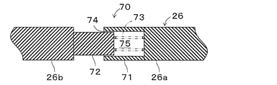
操作力伝達機構70は、オペレーティングロッド26を構成するブレーキペダル21側部分である第1オペレーティングロッド26a(第1ロッド)と、マスタシリンダ23側部分である第2オペレーティングロッド26b(第2ロッド)の接合部に設けられている。具体的には、第1オペレーティングロッド26aの一端は、ブレーキペダル21に接続されている。第1オペレーティングロッド26aの他端部(先端部)には筒部71(外側筒部)が形成されている。筒部71は、先端が開口した有底筒状に形成されている。第2オペレーティングロッド26bの他端は、プッシュロッド27等を介してマスタシリンダ23(第1ピストン23b)に接続されている。第2オペレーティングロッド26bの一端部(先端部)には、筒部71内に摺動可能に往復動するように収納される筒状係合部72(内側筒部)が形成されている。筒状係合部72は筒部71から抜けないようになっている。さらに、筒部71と筒状係合部72との間には両ロッド26a,26bを往復動方向に沿って離れる方向(内部空間75の容積が増大する方向)に付勢するスプリング73が収納されている。この操作力伝達機構70が基礎液圧制動力発生制限手段である。
The operating
第1オペレーティングロッド26aの先端部と第2オペレーティングロッド26bの先端部との間には、すなわち筒部71と筒状係合部72との間には、流体(本実施形態では空気)で満たされる内部空間75が形成されている。内部空間75の容積は、筒状係合部72の筒部71に対する相対移動によって変化するものである。流体として、気体だけでなく液体もある。
A fluid (air in this embodiment) is filled between the tip of the
操作力伝達機構70には、内部空間75の内外を連通して内部空間75内の流体が流入出する連通路74が備えられている。連通路74は、ブレーキペダル21の急踏み時には内部空間75からの流体の流出が制限され、非急踏み時には制限されないように構成されている。連通路74は、オリフィスである。このオリフィスは、第1オペレーティングロッド26aの筒部71と、第2オペレーティングロッド26bの筒状係合部72との隙間である。なお、急踏み時の踏み込み速度は、非急踏み時より速い。
The operating
このように構成した連結部材を有する液圧ブレーキ装置Bの作動を説明する。まず、ブレーキペダル21が踏込まれておらずマスタシリンダ圧(基礎液圧)が形成されておらず、かつブレーキアクチュエータ25が作動しておらず制動液圧が形成されていない場合、操作力伝達機構70は、図3の状態であり、オペレーティングロッド26はスプリング73の付勢力によって最大長となっている。
The operation of the hydraulic brake device B having the connecting member configured as described above will be described. First, when the
ブレーキペダル21が非急踏みされる場合には、操作力伝達機構70の内部空間75からの流体の流出が連通路74により制限されない。このとき、内部空間75の容積は小さくなるが、内部空間75内の空気はほとんど圧縮されない。よって、第2オペレーティングロッド26bが第1オペレーティングロッド26aに摺動している状態にあり、第1オペレーティングロッド26aが第2オペレーティングロッド26bに直接当接するまでは第2オペレーティングロッド26bは押圧されない。
When the
なお、第2オペレーティングロッド26bが第1オペレーティングロッド26aに摺動している状態とは、本実施形態のように停止している第2オペレーティングロッド26bに第1オペレーティングロッド26aが摺動していることをいう。
The state where the
すなわち、ブレーキペダル21が非急踏みされると、操作力によって第1オペレーティングロッド26aはスプリング73の付勢力に抗して第2オペレーティングロッド26bの方に移動される。このとき、スプリング73の付勢力は第2オペレーティングロッド26bを元に戻す負圧式ブースタ22のリターンスプリングおよびマスタシリンダ23のスプリング23e,23gの各付勢力より小となるように設定されているので、スプリング73は圧縮されるが第2オペレーティングロッド26bは移動されない。すなわち、マスタシリンダ23にてマスタシリンダ圧が形成されるのが制限されるため、マスタシリンダ圧がホイールシリンダWC1,WC2,WC3,WC4に付与されない。
That is, when the
さらに、ブレーキペダル21が踏まれて筒部71内の筒状係合部72の先端部が筒部71の底に当接すると(または筒部71の一端面が筒状係合部72の段部に当接すると)、それ以降操作力によって第1オペレーティングロッド26aとともに第2オペレーティングロッド26bが移動される。すなわち、マスタシリンダ23にてマスタシリンダ圧が形成され始め、ブレーキペダル21の踏み込みによって発生したマスタシリンダ圧がホイールシリンダWC1,WC2,WC3,WC4に付与される。そして、ブレーキペダル21の踏み込みが解除されると、スプリング73の付勢力によって操作力伝達機構70は図3の状態に戻される。
Further, when the
この液圧ブレーキ装置Bによって形成される基礎液圧による基礎液圧制動力は図5の破線にて示すようになる。すなわち、ブレーキペダルストロークが踏み込み開始位置から第1オペレーティングロッド26aが第2オペレーティングロッド26bに当接する位置(当接位置)までの間に位置する場合は、マスタシリンダ23の第1および第2液圧室23d,23fに発生する基礎液圧は0に制限されるため、基礎液圧制動力の発生も0に制限されている。そして、ブレーキペダルストロークが、第1オペレーティングロッド26aが第2オペレーティングロッド26bに当接する位置を越える位置に位置する場合は、前述した基礎液圧の発生制限が解除されて、第1および第2液圧室23d,23fに発生する基礎液圧はブレーキペダルストロークに対応したものとなるため、基礎液圧制動力もブレーキペダルストロークに対応したものとなる。なお、第1オペレーティングロッド26aが第2オペレーティングロッド26bに当接する位置に位置する状態が所定状態であり、基礎液圧制動力がブレーキペダルストロークに対応した昇圧を開始するブレーキ操作状態である。したがって、図5の破線にて示すように、基礎液圧をホイールシリンダWC1,WC2,WC3,WC4に直接付与することにより、同各車輪FL,FR,RL,RRに基礎液圧に対応した基礎液圧制動力を発生させることができる。
The basic hydraulic braking force by the basic hydraulic pressure formed by the hydraulic brake device B is as shown by the broken line in FIG. That is, when the brake pedal stroke is located between the depression start position and the position (contact position) where the
なお、所定状態は、基礎液圧制動力の発生制限が解除されて、基礎液圧制動力がブレーキ操作状態に対応した昇圧を開始するブレーキ操作状態である。また、踏込開始位置から当接位置までの距離である所定距離s(図3に示すsと同義である。)は、ブレーキ操作状態が所定状態であるときに回生ブレーキ装置Aが最大回生制動力を発生するように設定されることが望ましい。これにより、ブレーキ操作状態が所定状態となった場合に、マスタシリンダ23は基礎液圧制動力の発生の制限を解除するとともに回生ブレーキ装置Aは最大回生制動力を発生する。なお、図3に示すsは、踏み込み状態にないプッシュロッド26において、第1オペレーティングロッド26aの筒部71の一端面と、第2オペレーティングロッド26bの筒状係合部72の段部との距離である。
The predetermined state is a brake operation state in which the generation restriction of the base hydraulic pressure braking force is released and the base hydraulic pressure braking force starts increasing the pressure corresponding to the brake operation state. Further, a predetermined distance s (synonymous with s shown in FIG. 3) from the stepping start position to the contact position is the maximum regenerative braking force when the regenerative braking device A is in the predetermined state. It is desirable to set so as to generate Thereby, when the brake operation state becomes a predetermined state, the
一方、ブレーキペダル21が急踏みされる場合には、操作力伝達機構70の内部空間75からの流体の流出が連通路74により制限される。このとき、例えば内部空間75内に圧縮空気が形成されることで、第1オペレーティングロッド26aが第2オペレーティングロッド26bに直接当接する前に、第1オペレーティングロッド26aは圧縮空気を介して第2オペレーティングロッド26bおよびプッシュロッド27を押圧する。よって、第2オペレーティングロッド26bが第1オペレーティングロッド26aと共に移動している状態にあるため、プッシュロッド27によって第1ピストン23bが押されて第1ポート23hを塞ぐことで、第1液圧室23dに基礎液圧が発生する。すなわち、基礎液圧制動力発生制限手段が、第1オペレーティングロッド26aが踏み込み開始位置から当接位置となるまでの間にて基礎液圧制動力を発生させる。これにより、運転者がブレーキペダル21を急踏みすると、第1オペレーティングロッド26aが踏み込み開始位置から当接位置までの間を位置する場合は基礎液圧制動力を積極的に発生させることができる。
On the other hand, when the
なお、第2オペレーティングロッド26bが第1オペレーティングロッド26aと共に移動している状態とは、第1オペレーティングロッド26aが第2オペレーティングロッド26bに直接当接する前に、両ロッド26a,26bが共に移動している状態のことである。
The state in which the
また、この間はブレーキ操作状態に対応した車両制動力を達成するための液圧ブレーキ装置Bとの協調動作によって、回生ブレーキ装置Aが車両制動力に対する基礎液圧制動力の不足分を回生制動力によって補う。したがって、第1オペレーティングロッド26aが踏み込み開始位置から当接位置までの低踏力領域においては、ブレーキペダル21の急踏み時には、高回生効率・高燃費より優先して基礎液圧制動力の早期付与を図ることができる。
During this time, the regenerative braking device A uses the regenerative braking force to compensate for the shortage of the basic hydraulic braking force relative to the vehicle braking force by the cooperative operation with the hydraulic brake device B for achieving the vehicle braking force corresponding to the brake operation state. compensate. Therefore, in the low pedaling force range from the stepping start position to the contact position of the
この液圧ブレーキ装置Bによって形成される基礎液圧による基礎液圧制動力は図5の実線にて示すようになる。すなわち、ブレーキペダルストロークが踏み込み開始位置から第1ポート23hを完全に閉鎖する閉鎖位置(ポート閉鎖位置)までの間に位置する場合は、基礎液圧は発生が制限されないでペダルストロークに応じて発生する。さらに、ブレーキペダルストロークが、閉鎖位置から第1オペレーティングロッド26aが第2オペレーティングロッド26bに当接する位置(当接位置)までに位置する場合は、第1ポート23hが完全に閉鎖されることで基礎液圧はより増大されるため(増大量が増加するため)、より大きい基礎液圧が発生する。そして、ブレーキペダルストロークが、当接位置を越える位置に位置する場合は、第1および第2液圧室23d,23fに発生する基礎液圧はブレーキペダルストロークに対応したものとなるため、基礎液圧制動力もブレーキペダルストロークに対応したものとなる。
The basic hydraulic braking force by the basic hydraulic pressure formed by the hydraulic brake device B is as shown by the solid line in FIG. In other words, when the brake pedal stroke is located between the depression start position and the closed position (port closed position) where the
なお、本実施形態では、ポート閉鎖位置は、踏み込み開始位置と当接位置との間になるように設定されている。また、ポート閉鎖位置は、当接位置を越えた位置に設定するようにしてもよい。 In this embodiment, the port closing position is set to be between the stepping start position and the contact position. Further, the port closing position may be set to a position beyond the contact position.
また、急踏み時の基礎液圧制動力と非急踏み時の基礎液圧制動力の傾きは、マスタシリンダ23や負圧式ブースタ22の特性によって決定されるものであり、同一の特性を有する。また、踏み込み開始時点から第1ピストン23bが押されるため、急踏み時の基礎液圧制動力の立上り時点は、非急踏み時に比べて早くなっている。
In addition, the slopes of the basic hydraulic braking force at the time of sudden depression and the basic hydraulic braking force at the time of non-rapid depression are determined by the characteristics of the
次に、ブレーキアクチュエータ25について図4を参照して詳述する。このブレーキアクチュエータ25は、一般的によく知られているものであり、液圧制御弁31,41、ABS制御弁を構成する増圧制御弁32,33,42,43および減圧制御弁35,36,45,46、調圧リザーバ34,44、ポンプ37,47、モータMなどを一つのケースにパッケージすることにより構成されている。
Next, the
まず、ブレーキアクチュエータ25の前輪系統の構成について説明する。油経路Lfには、差圧制御弁から構成される液圧制御弁31が備えられている。この液圧制御弁31は、ブレーキECU60により連通状態と差圧状態を切り替え制御されるものである。液圧制御弁31は通常連通状態とされているが、差圧状態にすることによりホイールシリンダWC1,WC2側の油経路Lf2をマスタシリンダ23側の油経路Lf1よりも所定の差圧分高い圧力に保持することができる。この差圧はブレーキECU60により制御電流に応じて調圧されるようになっている。
First, the configuration of the front wheel system of the
油経路Lf2は2つに分岐しており、一方にはABS制御の増圧モード時においてホイールシリンダWC1へのブレーキ液圧の増圧を制御する増圧制御弁32が備えられ、他方にはABS制御の増圧モード時においてホイールシリンダWC2へのブレーキ液圧の増圧を制御する増圧制御弁33が備えられている。これら増圧制御弁32,33は、ブレーキECU60により連通・遮断状態を制御できる2位置弁として構成されている。そして、これら増圧制御弁32,33が連通状態に制御されているときには、マスタシリンダ23の基礎液圧または/およびポンプ37の駆動と液圧制御弁31の制御によって形成される制御液圧を各ホイールシリンダWC1,WC2に加えることができる。また、増圧制御弁32,33は減圧制御弁35,36およびポンプ37とともにABS制御を実行することができる。
The oil path Lf2 is branched into two, one of which is provided with a pressure
なお、ABS制御が実行されていないノーマルブレーキの際には、これら増圧制御弁32,33は常時連通状態に制御されている。また、増圧制御弁32,33には、それぞれ安全弁32a,33aが並列に設けられており、ABS制御時においてブレーキペダル21を離したとき、それに伴ってホイールシリンダWC1,WC2側からのブレーキ液をリザーバタンク24に戻すようになっている。
Note that, during normal braking in which ABS control is not being executed, these pressure
また、増圧制御弁32,33と各ホイールシリンダWC1,WC2との間における油経路Lf2は、油経路Lf3を介して調圧リザーバ34に連通されている。油経路Lf3には、ブレーキECU60により連通・遮断状態を制御できる減圧制御弁35,36がそれぞれ配設されている。これらの減圧制御弁35,36はノーマルブレーキ状態(ABS非作動時)では常時遮断状態とされ、また、適宜連通状態として油経路Lf3を通じて調圧リザーバ34へブレーキ液を逃がすことにより、ホイールシリンダWC1,WC2におけるブレーキ液圧を制御し、車輪がロック傾向にいたるのを防止できるように構成されている。
The oil path Lf2 between the pressure
さらに、液圧制御弁31と増圧制御弁32,33との間における油経路Lf2と調圧リザーバ34とを結ぶ油経路Lf4にはポンプ37が安全弁37aと共に配設されている。そして、調圧リザーバ34を油経路Lf1を介してマスタシリンダ23と接続するように油経路Lf5が設けられている。ポンプ37は、ブレーキECU60の指令によりモータMによって駆動されるものである。ポンプ37は、ABS制御の減圧モード時においては、ホイールシリンダWC1,WC2内のブレーキ液または調圧リザーバ34に貯められているブレーキ液を吸い込んで連通状態である液圧制御弁31を介してマスタシリンダ23に戻している。また、ポンプ37は、VSC制御、トラクションコントロール、ブレーキアシストなどの車両の姿勢を安定に制御するための制御液圧を形成する際においては、差圧状態に切り替えられている液圧制御弁31に差圧を発生させるべく、マスタシリンダ23内のブレーキ液を油経路Lf1,Lf5および調圧リザーバ34を介して吸い込んで油経路Lf4,Lf2および連通状態である増圧制御弁32,33を介して各ホイールシリンダWC1,WC2に吐出して制御液圧を付与している。なお、ポンプ37が吐出したブレーキ液の脈動を緩和するために、油経路Lf4のポンプ37の上流側にはアキュムレータ38が配設されている。
Further, a
また、油経路Lf1には、マスタシリンダ23内のブレーキ液圧であるマスタシリンダ圧を検出する圧力センサPが設けられており、この検出信号はブレーキECU60に送信されるようになっている。なお、圧力センサPは油経路Lr1に設けるようにしてもよい。
The oil path Lf1 is provided with a pressure sensor P that detects a master cylinder pressure that is a brake fluid pressure in the
さらに、ブレーキアクチュエータ25の後輪系統も前述した前輪系統と同様な構成であり、後輪系統を構成する油経路Lrは油経路Lfと同様に油経路Lr1〜Lr5から構成されている。油経路Lrには液圧制御弁31と同様な液圧制御弁41、および調圧リザーバ34と同様な調圧リザーバ44が備えられている。ホイールシリンダWC3,WC4に連通する分岐した油経路Lr2,Lr2には増圧制御弁32,33と同様な増圧制御弁42,43が備えられ、油経路Lr3には減圧制御弁35,36と同様な減圧制御弁45,46が備えられている。油経路Lr4には、ポンプ37、安全弁37aおよびアキュムレータ38と同様なポンプ47、安全弁47aおよびアキュムレータ48が備えられている。なお、増圧制御弁42,43には、それぞれ安全弁32a,33aと同様な安全弁42a,43aが並列に設けられている。
Further, the rear wheel system of the
これにより、ポンプ37,47の駆動と液圧制御弁31,41の制御によって形成された制御液圧を各車輪FL,FR,RL,RRのホイールシリンダWC1,WC2,WC3,WC4に付与することにより各車輪FL,FR,RL,RRに制御液圧制動力を発生させることができる。
Thereby, the control hydraulic pressure formed by the drive of the
そして、車両用ブレーキ装置は、主として図1に示すように、ペダルストロークセンサ21a、各車輪FL,FR,RL,RRの車輪速度をそれぞれ検出する各車輪速センサSfl,Sfr,Srl,Srr、圧力センサP、各制御弁31,32,33,35,36,41,42,43,45,46,モータMに接続されたブレーキECU(電子制御ユニット)60を備えている。ブレーキECU60は、これら各センサによる検出及びシフトスイッチの状態に基づき、液圧ブレーキ装置Bの各制御弁31,32,33,35,36,41,42,43,45,46の状態を切り換え制御または通電電流制御しホイールシリンダWC1〜WC4に付与する制御液圧すなわち各車輪FL,FR,RL,RRに付与する制御液圧制動力を制御する。
As shown in FIG. 1, the vehicle brake device mainly includes a
さらに、ブレーキECU60はハイブリッドECU19に互いに通信可能に接続されており、車両の全制動力が油圧ブレーキだけの車両と同等となるようにモータ12が行う回生ブレーキと油圧ブレーキの協調制御を行っている。具体的には、ブレーキECU60は運転者の制動要求すなわち制動操作状態に対して、ハイブリッドECU19に全制動力のうち回生ブレーキ装置の負担分である回生要求値を回生ブレーキ装置の目標値すなわち目標回生制動力として出力する。ハイブリッドECU19は、入力した回生要求値(目標回生制動力)に基づいて車速やバッテリ充電状態等を考慮して実際に回生ブレーキとして作用させる実回生実行値を導出しその実回生実行値に相当する回生制動力を発生させるようにインバータ16を介してモータ12を制御するとともに、導出した実回生実行値をブレーキECU60に出力している。
Furthermore, the
さらに、ブレーキECU60は、基礎液圧がホイールシリンダWC1,WC2,WC3,WC4に供給されたとき、ブレーキ手段BK1,BK2,BK3,BK4が車輪FL,FR,RL,RRに付与する基礎液圧制動力をマップ、テーブルまたは演算式にしてメモリに予め記憶している。また、ブレーキECU60は、ブレーキペダルのストローク(またはマスタシリンダ圧)であるブレーキ操作状態に応じて車輪FL,FR,RL,RRに付与する目標回生制動力をマップ、テーブルまたは演算式にしてメモリに予め記憶している。また、ブレーキECU60には、図6に示す協調制御プログラム(車両用ブレーキ制御プログラム)が記憶されている。
Further, the
次に、上記のように構成した車両用ブレーキ装置の作動を図6のフローチャートに沿って説明する。ブレーキECU60は、例えば車両のイグニションスイッチ(図示省略)がオン状態にあるとき、上記フローチャートに対応したプログラムを所定の短時間毎に実行する。ブレーキECU60は、ブレーキペダル21の操作状態であるペダルストロークをペダルストロークセンサ21aから入力し(ステップ102)、入力したペダルストロークに応じた目標回生制動力を演算する(ステップ104)。このとき、ブレーキECU60は、予め記憶しておいたペダルストロークすなわちブレーキ操作状態と車輪FL,FR,RL,RRに付与する目標回生制動力との関係を示すマップ、テーブルまたは演算式を使用する。
Next, the operation of the vehicle brake device configured as described above will be described with reference to the flowchart of FIG. For example, when the ignition switch (not shown) of the vehicle is in an on state, the
目標回生制動力が0より大きい場合には、ステップ104にて演算した目標回生制動力をハイブリッドECU19に出力するとともに、ブレーキアクチュエータ25に対して制御を行わない(ステップ106,108)。したがって、ブレーキペダル21が踏まれている場合、前述した場合と同様に、液圧ブレーキ装置Bは車輪FL,FR,RL,RRに基礎液圧制動力(静圧ブレーキ)のみを付与する。また、ハイブリッドECU19は、目標回生制動力を示す回生要求値を入力し、その値に基づいて車速やバッテリ充電状態等を考慮して回生制動力を発生させるようにインバータ16を介してモータ12を制御するとともに、実回生実行値をブレーキECU60に出力している。したがって、ブレーキ操作がされて、かつ目標回生制動力が0より大きい場合には、車輪FL,FR,RL,RRには基礎液圧制動力に回生制動力が上乗せされて付与される。このように回生協調制御が実行されるが、このとき基礎液圧制動力と回生制動力はブレーキ操作力に応じているので、その一例が図5に示されている。図5には、回生協調制御時のブレーキ操作力と、基礎液圧制動力と回生制動力との総和を示す制動力との相関関係が示されている。
If the target regenerative braking force is greater than 0, the target regenerative braking force calculated in
すなわち、本第1の実施の形態によるマスタシリンダ23(基礎液圧制動力発生制限手段)によれば、ブレーキペダル21の非急踏み時に、ブレーキ操作状態が踏み込み開始時点の状態である踏み込み開始状態から所定状態となるまでの間は基礎液圧制動力が所定値以下となるようにその発生を制限する。これにより、運転者がブレーキペダル21を踏み込むと、図5の破線で示すように、踏み込み開始状態から所定状態までの間は基礎液圧制動力が所定値以下に強制的に制限されるので、この間回生制動力のみがブレーキ操作状態に応じて付与される。また、ブレーキ操作状態が所定状態となった場合においては、基礎液圧制動力の発生の制限を解除するとともに、回生ブレーキ装置Aは最大回生制動力を発生するので、最大回生制動力のみが付与される。さらに、ブレーキ操作状態が所定状態より踏み込み状態となった場合においては、基礎液圧制動力の発生の制限の解除が維持されて、液圧ブレーキ装置Bと回生ブレーキ装置Aとを協調動作させて基礎液圧制動力と回生制動力(基本的には最大回生制動力である。)に基づいてブレーキ操作状態に対応した車両制動力が付与される。
That is, according to the master cylinder 23 (basic hydraulic braking force generation limiting means) according to the first embodiment, when the
一方、ブレーキペダル21の急踏み時には、基礎液圧制動力の発生を制限することなく、図5の実線で示すように、踏みこみ開始時点から基礎液圧制動力が付与される。
On the other hand, when the
ブレーキECU60は、回生ブレーキ装置Aによって実際に生成された回生制動力の変動を検出する(ステップ110〜114)。具体的には、ブレーキECU60は、ステップ104にて演算された目標回生制動力に対して回生ブレーキ装置Aが実際に車輪FL,FR,RL,RRに付与した実回生制動力を示す実回生実行値を入力し(ステップ110)、ステップ104にて演算された目標回生制動力とステップ110にて入力された実回生制動力の差を演算し(ステップ112)、この演算された差が所定値aより大きければ、回生制動力が変動したことを検出する(ステップ114)。
The
そして、ブレーキECU60は、回生制動力の変動を検出すると、ステップ114にてYESと判定し、液圧ブレーキ装置Bのポンプ37,47を駆動させるとともに液圧制御弁31,41を制御することによって制御液圧を形成して車輪FL,FR,RL,RRに制御液圧に基づく制御液圧制動力を付与することにより、上述のように検出された回生制動力の変動による制動力の不足を補償する(ステップ116)。具体的には、ブレーキECU60は、ステップ104にて演算された目標際動力と、ステップ110にて入力された実回生制動力との差、すなわちステップ112にて演算された差に相当する液圧となるように制御液圧を制御する。ブレーキECU60は、モータMを起動してポンプ37,47を駆動し、ポンプ37,47からホイールシリンダWC1,WC2,WC3,WC4に供給されるブレーキ液の液圧が制御液圧となるように差圧制御弁31,41のリニアソレノイドに電流を印加する。このとき、リニアソレノイド33は液圧センサ40により検出されたホイールシリンダWC1,WC2,WC3,WC4の液圧が制御液圧となるようにフィードバック制御されるのがより好ましい。一方、ブレーキECU60は、回生制動力の変動を検出しない場合には、ステップ114にてNOと判定し、ブレーキアクチュエータ25の制御を停止する(ステップ118)。
When the
上述した説明から明らかなように、本第1の実施の形態によれば、ブレーキペダル21の非急踏み時において、オペレーティングロッド26に形成された操作力伝達機構70の内部空間75からの流体の流出が連通路74により制限されない。このとき、内部空間75の容積は小さくなるが、内部空間75内の流体はほとんど圧縮されないため、第2オペレーティングロッド26b(第2ロッド)が第1オペレーティングロッド26a(第1ロッド)に摺動している状態にあり、この状態では基礎液圧制動力の発生が制限される。これにより、運転者がブレーキペダル21を急踏みした場合、特に第1オペレーティングロッド26aが踏み込み開始位置から当接位置までの間を位置する場合は基礎液圧制動力が所定値以下に強制的に制限される。また、この間はブレーキ操作状態に対応した車両制動力を達成するための液圧ブレーキ装置Bとの協調動作によって、回生ブレーキ装置Aが前記車両制動力に対する基礎液圧制動力の不足分を回生制動力によって補う。したがって、運転者がブレーキペダル21を急踏みした場合、特に第1オペレーティングロッド26aが踏み込み開始位置から当接位置までの低踏力領域においては、回生制動力を積極的に利用することになり、高回生効率、すなわち高燃費を達成することができる。
As is clear from the above description, according to the first embodiment, when the
一方、ブレーキペダル21の急踏み時において、内部空間75からの流体の流出が連通路74により制限される。このとき、例えば内部空間75内に圧縮空気が形成されることで、第1オペレーティングロッド26aが第2オペレーティングロッド26bに直接当接する前に、第1オペレーティングロッド26aは圧縮空気を介して第2ロッドを押圧する。よって、第2オペレーティングロッド26bが第1オペレーティングロッド26aと共に移動している状態にあり、この状態では基礎液圧制動力の発生の抑制が解除される。すなわち、操作力伝達機構70(基礎液圧制動力発生制限手段)が、第1オペレーティングロッド26aが踏み込み開始位置から当接位置となるまでの間にて基礎液圧制動力を発生させる。これにより、運転者がブレーキペダル21を急踏みした場合、第1オペレーティングロッド26aが踏み込み開始位置から当接位置までの間を位置する場合は基礎液圧制動力を積極的に発生させることができる。また、この間はブレーキ操作状態に対応した車両制動力を達成するための液圧ブレーキ装置Bとの協調動作によって、回生ブレーキ装置Aが前記車両制動力に対する基礎液圧制動力の不足分を回生制動力によって補う。したがって、第1オペレーティングロッド26aが踏み込み開始位置から当接位置までの低踏力領域においては、ブレーキペダル21の急踏み時には、高回生効率・高燃費より優先して基礎液圧制動力の早期付与を図ることができる。
On the other hand, when the
以上のように、車両用ブレーキ装置において、ブレーキペダル21の踏み込み開始時点から所定状態となるまでの低踏力領域において、非急踏み時では回生制動力を積極的に利用することにより、高回生効率、高燃費を達成するとともに、急踏み時には基礎液圧制動力をできるだけ早期に付与することの両立を図ることができる。
As described above, in the vehicular brake device, in a low pedaling force region from when the
また、連通路74はオリフィスである。よって、簡単な構成で内部空間75からの流体の流出を絞ることができる。
The
また、オリフィスは、第1オペレーティングロッド26aと第2オペレーティングロッド26bとの隙間74である。よって、簡便な構成かつ低コストにて内部空間75からの流体の流出を絞ることができる。
The orifice is a
また、第1オペレーティングロッド26aの先端部および第2オペレーティングロッド26bの先端部の少なくともいずれか一方は先端に開口した有底筒状の筒部71を有し、他方は筒部71内を摺動し、内部空間75は外側筒部71および内側筒部72の内側に形成されている。これにより、ブレーキペダル21の急踏み時において内部空間75内に圧縮空気を形成することを、容易かつ簡単な構成で達成することができる。
Further, at least one of the distal end portion of the
また、ブレーキペダル21の非急踏み時には、ブレーキペダル21の踏み込みが開始されてから筒部71内の筒状係合部72の先端部が当該筒部71の底に当接するまでの期間中、第2オペレーティングロッド26bが第1オペレーティングロッド26aに摺動して、基礎液圧制動力の発生が制限され、一方、ブレーキペダル21の急踏み時には、ブレーキペダル21の踏み込みが開始されてから筒部71内の筒状係合部72の先端部が当該筒部71の底に当接する前に、第1オペレーティングロッド26aが内部空間75内で圧縮された流体を介して第2オペレーティングロッド26bを押圧して、基礎液圧制動力の発生の制限が解除される。したがって、ブレーキペダル21の踏み込みが開始されてから筒部71内の筒状係合部72の先端部が当該筒部71の底に当接するまでの期間中すなわち低踏力領域において、ブレーキペダル21の非急踏み時には、回生制動力を積極的に利用することになり、高回生効率、すなわち高燃費を達成することができる。一方、ブレーキペダル21の急踏み時には、高回生効率・高燃費より優先して基礎液圧制動力の早期付与を図ることができる。
Further, when the
また、筒部71内の筒状係合部72の先端部が当該筒部71の底に当接するブレーキペダル21の踏み込み位置は、回生ブレーキ装置Aが発生可能な最大回生制動力に基づいて設定されている。これにより、ブレーキペダル21の非急踏み時において、ブレーキペダルストロークが前記当接位置を越えた位置に位置する場合は、液圧ブレーキ装置Bが発生させる基礎液圧制動力と回生ブレーキ装置Aが発生させる最大回生制動力とによりブレーキペダルの操作状態に対応した車両制動力を車両に付与することができ、高回生効率を実現することができる。
Further, the depression position of the
なお、上述した第1の実施の形態において、ブレーキ操作状態は、マスタシリンダ23のストロークを検出するマスタシリンダストロークセンサ23zによって検出するようにしてもよい。
In the first embodiment described above, the brake operation state may be detected by a master
2)第2の実施形態
次に、本発明に係る車両用ブレーキ装置をハイブリッド車に適用した第2の実施形態を図面を参照して説明する。上述した液圧ブレーキ装置Bの負圧式ブースタ22には、ブレーキアシスト装置は備えられていなかったが、本第2の実施形態に係る液圧ブレーキ装置Bの負圧式ブースタ122には、ブレーキアシスト装置が備えられている。ブレーキアシスト装置は、小さい踏力を補助して大きな制動力を形成して付与する装置である。
2) Second Embodiment Next, a second embodiment in which the vehicle brake device according to the present invention is applied to a hybrid vehicle will be described with reference to the drawings. The
図7において、負圧式ブースタ122は、前方シェル81aと後方シェル81b及び可動壁82とから構成され、内部が可動壁82によって定圧室R1と変圧室R2とに分割されるハウジング81を備える。ハウジング81内の可動壁82は、金属製のプレート82aとゴム製のダイアフラム82bとから成り、ハウジング81に対して前後方向移動可能に設置されている。
In FIG. 7, the
定圧室R1は、負圧源であるエンジンインテークマニホールド(図示せず)に連通され、エンジン作動中は常に負圧に保たれる。変圧室R2は、通路83及び弁機構84を介して定圧室R1と連通、遮断されるとともに、弁機構84を介して大気とも連通、遮断される。
The constant pressure chamber R1 communicates with an engine intake manifold (not shown), which is a negative pressure source, and is always kept at a negative pressure during engine operation. The variable pressure chamber R <b> 2 communicates with the constant pressure chamber R <b> 1 through the
図8に示すように、負圧式ブースタ122においては、運転者が慌ててブレーキペダル21を踏み込む急踏み時において、オペレーティングロッド26とパワーピストン85との相対移動量が所定値Aより大きくなると、プランジャ86の斜面部86bが、保持部材87のテーパ部87aに当接するとともに、リング状弾性体88により縮径する方向に付勢されている保持部材87を半径方向に拡径させる。
As shown in FIG. 8, in the negative
テーパ部87aの最小内径部87a1がプランジャ86の段部86dに乗り上げると、弁座部材89の被係合部89cと保持部材87の係合部87bとの係合が解徐される。弁座部材89は、スプリング91により後方に付勢されているため、被係合部89cの係合が解徐されると直ちに、スプリング91の付勢力により後方に移動する。
When the minimum inner diameter portion 87a1 of the
弁座部材89が後方に移動すると、弁座部材89の第2負圧弁座92は、弁機構84の可動部93を構成する弁93aに当接し、定圧室R1と変圧室R2との連通を遮断する。このとき、プランジャ86は、オペレーティングロッド26と一体で前方へ移動中であり、弁座部材89が弁機構84の可動部93を後方へ推し戻しているため、プランジャ86の大気弁座86aと弁機構84の可動部93を構成する弁93bとが急速に離間し、変圧室R2が大気と連通する。その結果、通常ブレーキ動作に比べ、定圧室R1と変圧室R2との連通遮断及び変圧室R2が大気との連通が急速に行われるとともに、実質的に、パワーピストン85の反力部材94への当接面85dと第1負圧弁座95との距離、及びパワーピストン85の反力部材94への当接面85dと大気弁座86aとの距離を拡大することになり、ジャンピング状態での出力を通常状態よりも大きくすることが可能となる。
When the
本実施形態の負圧式ブースタの緊急ブレーキ特性は、ジャンピング特性を変化させて、通常ブレーキ時より大きな推進力が出力部材に印加されることによって達成されるものである。ジャンピング特性を変化させるためには、図8において、当接部材96と反力部材94との間隙Bを大きくすればよい。間隙Bの拡大は、パワーピストン85の反力部材94への当接面85dと第1負圧弁座95との距離、及びパワーピストン85の反力部材94への当接面85dと大気弁座86aとの距離を拡大することと同じである。すなわち、負圧弁座38と大気弁座86aとを後方に移動させることにより間隙Bを拡大し、当接部材96が反力部材94から反力を受けるまでの出力を大きくして、入力に対する出力の比率が無限大になるいわゆるジャンピング状態での出力を通常状態よりも大きくしたものである。
The emergency brake characteristic of the negative pressure type booster of this embodiment is achieved by changing the jumping characteristic and applying a larger propulsive force to the output member than during normal braking. In order to change the jumping characteristics, the gap B between the
通常ブレーキ特性と上記緊急ブレーキ特性とを図9に示す。図9において、通常ブレーキにおけるジャンンピングは、F1の大きさの出力しか得られないが、緊急ブレーキ時のジャンピングは、F2にまで増大し、小さなペダル踏力で十分な大きさのブレーキ液圧を発生させることができる。 The normal brake characteristics and the emergency brake characteristics are shown in FIG. In FIG. 9, the jumping in the normal brake can output only the magnitude of F1, but the jumping during emergency braking increases to F2 and generates a sufficiently large brake fluid pressure with a small pedal effort. Can be made.
なお、本第2の実施形態に係る負圧式ブースタにおいては、第1オペレーティングロッド26aが踏み込み開始位置から当接位置までの間に、ブレーキアシストが開始されるようになっている。
In the negative pressure type booster according to the second embodiment, the brake assist is started between the
上述した説明から明らかなように、本第2の実施形態によれば、ブレーキペダル21の非急踏み時において、オペレーティングロッド26に形成された操作力伝達機構70の内部空間75からの流体の流出が連通路74により制限されない。よって、上述した第1の実施形態と同様な作用・効果を得ることができる。
As is clear from the above description, according to the second embodiment, when the
一方、ブレーキペダル21が急踏みされる場合には、操作力伝達機構70の内部空間75からの流体の流出が連通路74により制限される。よって、内部空間75内に圧縮空気が形成されることで、第1オペレーティングロッド26aが第2オペレーティングロッド26bに直接当接する前に、第1オペレーティングロッド26aは圧縮空気を介して第2オペレーティングロッド26bおよびプッシュロッド27を押圧する。よって、プッシュロッド27によって第1ピストン23bが押されて第1ポート23hを塞ぐことで、第1液圧室23dに基礎液圧が発生する。すなわち、基礎液圧制動力発生制限手段が、第1オペレーティングロッド26aが踏み込み開始位置から当接位置となるまでの間にて基礎液圧制動力を発生させる。すなわち、第2オペレーティングロッド26bが第1オペレーティングロッド26aと共に移動している状態である。これにより、運転者がブレーキペダル21を急踏みすると、第1オペレーティングロッド26aが踏み込み開始位置から当接位置までの間を位置する場合は基礎液圧制動力を積極的に発生させることができる。
On the other hand, when the
この液圧ブレーキ装置Bによって形成される基礎液圧による基礎液圧制動力は図9の太い実線にて示すようになる。すなわち、ブレーキペダルストロークが踏み込み開始位置からブレーキアシストが開始されるブレーキアシスト開始位置(以下、BA開始位置という。)までの間に位置する場合は、第1の実施形態に係る急踏み時の基礎液圧制動力と同様に、基礎液圧は発生が制限されないでペダルストロークに応じて発生する。さらに、ブレーキペダルストロークが、BA開始位置を越える位置に位置する場合は、ブレーキアシスト装置による基礎液圧制動力がブレーキペダルストロークに対応して付与される。このように、ブレーキペダル21の急踏み時には、ブレーキアシスト装置は、第2オペレーティングロッド26bが第1オペレーティングロッド26aと共に移動している状態で作動する。
The basic hydraulic braking force by the basic hydraulic pressure formed by the hydraulic brake device B is as shown by a thick solid line in FIG. That is, when the brake pedal stroke is located between the depression start position and the brake assist start position where the brake assist is started (hereinafter referred to as the BA start position), the basics at the time of sudden depression according to the first embodiment. Similar to the hydraulic braking force, the basic hydraulic pressure is generated according to the pedal stroke without being restricted. Further, when the brake pedal stroke is located at a position exceeding the BA start position, the basic hydraulic braking force by the brake assist device is applied corresponding to the brake pedal stroke. Thus, when the
以上のように、車両用ブレーキ装置において、ブレーキペダル21の踏み込み開始時点から所定状態となるまでの低踏力領域において、非急踏み時では回生制動力を積極的に利用することにより、高回生効率、高燃費を達成するとともに、急踏み時にはブレーキアシスト装置による比較的大きな基礎液圧制動力を早期かつ確実に付与することができる。
As described above, in the vehicular brake device, in a low pedaling force region from when the
なお、上述した第2の実施形態において、ブレーキアシスト装置をいわゆるメカ式ブレーキアシストで構成するようにしたが、電磁弁で構成された大気圧弁を別に設けこの弁を開閉制御するようにしてもよく、また制御液圧を発生できるブレーキアクチュエータ15で構成するようにしてもよい。この場合、ブレーキ液圧装置Bには、高圧なブレーキ液を蓄圧できるアキュムレータを備えるのが好ましい。これにより、高い圧力の制御液圧を早期に付与することができる。
In the second embodiment described above, the brake assist device is configured by a so-called mechanical brake assist. However, an atmospheric pressure valve configured by an electromagnetic valve may be separately provided to control opening and closing of the valve. Alternatively, the
3)第3の実施形態
次に、本発明に係る車両用ブレーキ装置をハイブリッド車に適用した第3の実施形態を図10〜図12を参照して説明する。上述した第1および第2の実施形態においては、操作力伝達機構70に備えられた連通路74(オリフィス)は、第1オペレーティングロッド26aの筒部71と、第2オペレーティングロッド26bの筒状係合部72との隙間である。本第3の実施形態では、連通路74は、筒部71および筒状係合部72の少なくとも何れか一方の側壁に設けられた貫通孔(オリフィス)で構成されている。
3) Third Embodiment Next, a third embodiment in which the vehicle brake device according to the present invention is applied to a hybrid vehicle will be described with reference to FIGS. In the first and second embodiments described above, the communication path 74 (orifice) provided in the operating
具体的には、図10に示すように、貫通孔71aが筒部71に形成されている。貫通孔71aは軸方向のいずれの位置に形成してもよい。非急踏み時には、貫通孔71aからの流体の流出は制限されない。よって、第1オペレーティングロッド26aが移動するが、当接するまでは第2オペレーティングロッド26bは移動しないため、回生効率が向上する。
Specifically, as shown in FIG. 10, a through
一方、急踏み時において、貫通孔71aが筒状係合部72により閉鎖されるまでは、貫通孔71aからの流体の流出が制限される。よって、第2オペレーティングロッド26bが第1オペレーティングロッド26aとともに移動するため、早期に基礎液圧制動力を付与することができる。さらに、貫通孔71aが筒状係合部72により閉鎖された以降において、内部空間75はほぼ密封されるため、エアダンパ機能が発揮されることで、第1および第2オペレーティングロッド26a,26bが当接する際の衝撃を抑制することができる。
On the other hand, at the time of sudden depression, the outflow of fluid from the through
また、図11に示すように、貫通孔72aを筒状係合部72に形成するようにしてもよい。この場合においても、筒部71に貫通孔71aを形成した場合と同様な作用・効果を得ることができる。
Further, as shown in FIG. 11, a through
さらに、複数の貫通孔を軸方向に沿って並べて形成するようにしてもよい。例えば、図12に示すように、複数(本実施形態では3個)の貫通孔71aが筒部71に軸方向に沿って並べて形成されている。貫通孔71aは同径である。これにより、急踏み時において、ストローク量が増大するにしたがって閉鎖される貫通孔71aの数を減少させることで、すなわちストローク量が増大するにしたがって連通路74の流路断面積を小さくすることで、エアダンパ機能を高めることができる。なお、貫通孔71a径を異ならせてもよい。
Furthermore, a plurality of through holes may be formed side by side along the axial direction. For example, as shown in FIG. 12, a plurality (three in this embodiment) of through
4)第4の実施形態
次に、本発明に係る車両用ブレーキ装置をハイブリッド車に適用した第4の実施形態を図13を参照して説明する。第4の実施形態では、連通路74は、筒部71以外の第1オペレーティングロッド26aの部分および筒状係合部72以外の第2オペレーティングロッド26bの部分の少なくとも何れか一方に設けられた貫通孔で構成されている。具体的には、図13に示すように、貫通孔71bが第1オペレーティングロッド26aに形成されている。これによっても、第1の実施形態と同様な作用・効果を得ることができる。
4) Fourth Embodiment Next, a fourth embodiment in which the vehicle brake device according to the present invention is applied to a hybrid vehicle will be described with reference to FIG. In the fourth embodiment, the
5)第5の実施形態
次に、本発明に係る車両用ブレーキ装置をハイブリッド車に適用した第5の実施形態を図14を参照して説明する。第5の実施形態では、連通路74は、筒部71の内側面および筒状係合部72の外周面の少なくとも何れか一方に設けられた溝で構成されている。
5) Fifth Embodiment Next, a fifth embodiment in which the vehicle brake device according to the present invention is applied to a hybrid vehicle will be described with reference to FIG. In the fifth embodiment, the
具体的には、図14に示すように、溝72bが筒状係合部72の外周面に形成されている。溝72bは、筒状係合部72の先端から筒状係合部72の基端に達する前の位置まで軸方向に沿って延在する。溝72bの流路断面積は、筒状係合部72の先端から基端に行くにしたがって小さくなるようになっている。溝72bと筒部71の開口端内周との間から流体が入出する。
Specifically, as shown in FIG. 14, a
これにより、非急踏み時には、溝72bからの流体の流出は制限されない。よって、第1オペレーティングロッド26aが移動するが、当接するまでは第2オペレーティングロッド26bは移動しないため、回生効率が向上する。
Thereby, at the time of non-sudden stepping, the outflow of fluid from the
一方、急踏み時において、溝72bが筒部71により閉鎖されるまでは、溝72bからの流体の流出が制限される。よって、第2オペレーティングロッド26bが第1オペレーティングロッド26aとともに移動するため、早期に基礎液圧制動力を付与することができる。さらに、溝72bが筒部71により閉鎖された以降において、内部空間75はほぼ密封されるため、エアダンパ機能が発揮されることで、第1および第2オペレーティングロッド26a,26bが当接する際の衝撃を抑制することができる。
On the other hand, at the time of sudden depression, the outflow of fluid from the
なお、溝72bは、その流路断面積が延在方向で同一となるように構成するようにしてもよい。
In addition, you may make it comprise the groove |
6)第6の実施形態
次に、本発明に係る車両用ブレーキ装置をハイブリッド車に適用した第6の実施形態を図15を参照して説明する。第6の実施形態では、上述した図10に示すように筒部71または筒状係合部72に形成された貫通孔(連通路)に電磁弁を設けるようにした。
6) Sixth Embodiment Next, a sixth embodiment in which the vehicle brake device according to the present invention is applied to a hybrid vehicle will be described with reference to FIG. In the sixth embodiment, an electromagnetic valve is provided in a through hole (communication path) formed in the
例えば、図15に示すように、大気に開放された接続管76(流体通路)が、筒部71に形成された貫通孔71a(連通路)に接続されている。接続管76には、接続管76を開通または遮断する電磁弁77が設けられている。
For example, as shown in FIG. 15, a connection pipe 76 (fluid passage) opened to the atmosphere is connected to a through
非急踏み時には、非急踏みを検出するセンサによる非急踏みの検出によって電磁弁77が開状態とされ、貫通孔71aからの流体の流出は制限されない。一方、急踏み時には、急踏みを検出するセンサによる急踏みの検出によって電磁弁77が閉状態とされ、貫通孔71aからの流体の流出は制限される。
At the time of non-sudden stepping, the
7)その他の変形例
さらに、図16に示すように、第1オペレーティングロッド26aの筒部71を内側筒部とし、第2オペレーティングロッド26bの筒状係合部72を外側筒部としてもよい。
また、図17に示すように、内側筒部(筒状係合部72)の内部空間をなくしてもよい。
また、図18に示すように、Oリング78を設けるようにしてもよい。Oリング78は、弾性材で形成され、筒状係合部72の外周面に取付ければよい。Oリング78は、第1および第2オペレーティングロッド26a,26bが当接する際の衝撃を抑制する。
7) Other Modifications Furthermore, as shown in FIG. 16, the
Moreover, as shown in FIG. 17, you may eliminate the internal space of an inner side cylinder part (tubular engagement part 72).
Further, an O-
8)第7の実施形態
次に、本発明に係る車両用ブレーキ装置をハイブリッド車に適用した第7の実施形態を図19を参照して説明する。上述した第1の実施形態では反力用スプリング21bは線形ばねで構成されていたが、本第7の実施形態では反力用スプリング121bは非線形特性を有している。
8) Seventh Embodiment Next, a seventh embodiment in which the vehicle brake device according to the present invention is applied to a hybrid vehicle will be described with reference to FIG. In the first embodiment described above, the
具体的には、反力用スプリング121bは、図19に示すように、複数の線形ばねを組み合わせて構成されている。反力用スプリング121bは、異なるばね定数を有する複数(本実施形態では3個)の線形ばねを備えている。すなわち、反力用スプリング121bは、第1ばね121b1、第2ばね121b2、第3ばね121b3が直列に連結されて構成されている。ばね定数は、第1ばね121b1、第2ばね121b2、第3ばね121b3の順番に大きくなるようになっている。第1ばね121b1は第1ケース121b4内に所定距離S1の伸び代をおいて収納されており、所定距離S1伸びると第1ケース121b4によりそれ以上の伸びは規制されるようになっている。第2ばね121b2も第2ケース121b5内に所定距離S1の伸び代をおいて収納されており、所定距離S2伸びると第1ケース121b4によりそれ以上の伸びは規制されるようになっている。
Specifically, the
図19(a)は、第1ばね121b1、第2ばね121b2、第3ばね121b3が自然長の状態を示している。反力用スプリング121bに伸びる方向の力が作用すると、ばね定数の小さい第1ばね121b1から順番に伸び始める。図19(b)に示すように、第1ばね121b1の伸びが第1ケース121b4により規制され、次に第2ばね121b2の伸びが第2ケース121b5により規制される。
FIG. 19A shows a state in which the first spring 121b1, the second spring 121b2, and the third spring 121b3 are in a natural length. When a force in the extending direction acts on the
ところで、非急踏み時において、マスタシリンダ23とリザーバタンク24とがポート(第1の実施形態では第1ポート23hであり、第3の実施形態では第1ポート23hならびに第1ピストン側ポート223b1および第2ピストン側ポート223b2)を介して連通している状態では、マスタシリンダ圧によるブレーキペダル反力が得られない。また一般に、ブレーキペダルの踏込量(ペダルストローク)に対する踏力の特性(F−S特性)は、非線形である。
By the way, when the vehicle is not suddenly depressed, the
そこで、このように構成された本実施形態による反力用スプリング121bによれば、図21で太い実線で示すように、マスタシリンダ23とリザーバタンク24とが第1ポート23h(またはピストン用ポート123b1および第1ポート23h)を介して連通している状態において、すなわちペダルストロークが踏み込み開始位置から第1ポート23hを閉鎖する位置までの間において、反力用スプリング121bの撓みに対する荷重の特性を非線形としている。また、一般のブレーキペダルの踏込量(ペダルストローク)に対する踏力の特性(F−S特性)を細い実線で示す。図21に示すように、ブレーキ特性(F−S特性)は非線形である。本実施形態による反力用スプリングの特性は、踏み込み開始位置から閉塞位置までにおいては、通常のブレーキ特性と同様であり、閉塞位置以降においては線形である。これにより、ブレーキペダル21が踏み込まれて第1ピストン23b(または第1ピストン123b)が第1位置から第2位置となるまでの間(ブレーキペダル21の踏み込み開始から増圧方向に所定距離Sだけ移動するまでの間)、運転者に対しより良好なペダルフィーダを付与することができる。
Therefore, according to the
なお、反力用スプリング221bは、図20に示すように、線形ばねと非線形ばねを組み合わせて構成されるようにしてもよい。
The
具体的には、反力用スプリング221bは、非線形ばねである第1ばね221b1と、線形ばねである第2ばね221b2が直列に連結されて構成されている。ばね定数は、第1ばね221b1、第2ばね221b2の順番に大きくなるようになっている。第1ばね221b1は第1ケース221b3内に所定距離S1の伸び代をおいて収納されており、所定距離S1伸びると第1ケース221b3によりそれ以上の伸びは規制されるようになっている。
Specifically, the
図20(a)は、第1ばね221b1、第2ばね221b2が自然長の状態を示している。反力用スプリング221bに伸びる方向の力が作用すると、ばね定数の小さい第1ばね221b1から順番に伸び始める。図20(b)に示すように、第1ばね221b1の伸びが第1ケース221b3により規制される。
FIG. 20A shows a state in which the first spring 221b1 and the second spring 221b2 are in a natural length. When a force in the extending direction is applied to the
9)第8の実施形態
さらに、本発明に係る車両用ブレーキ装置をハイブリッド車に適用した第8の実施形態を図22を参照して説明する。本第8の実施形態では、反力用スプリング21bの撓みに対する荷重の特性は、マスタシリンダ23とリザーバタンク24とが連通していない状態において線形であり、その線形特性における撓みの増大に対する荷重の増加は、非線形特性における撓みの増大に対する荷重の増加以下である。
9) Eighth Embodiment Further, an eighth embodiment in which the vehicle brake device according to the present invention is applied to a hybrid vehicle will be described with reference to FIG. In the eighth embodiment, the load characteristic with respect to the deflection of the
一般に、所定踏力F1(例えば、500N)に対し所定範囲(例えば、0.25G以上)の減速度が得られることが望まれる。一方、踏力は、マスタシリンダ圧による反力と反力用スプリングによる付勢力の総和である。 Generally, it is desired that a deceleration within a predetermined range (for example, 0.25 G or more) is obtained with respect to a predetermined pedaling force F1 (for example, 500 N). On the other hand, the pedaling force is the sum of the reaction force due to the master cylinder pressure and the urging force due to the reaction force spring.
そこで、本実施形態による反力用スプリング21bによれば、反力用スプリングの撓みに対する荷重の特性を、マスタシリンダ23とリザーバタンク24とが連通している状態において非線形とするとともに、マスタシリンダ23とリザーバタンク24とが連通していない状態において線形とし、線形特性における撓みの増大に対する荷重の増加(図22にて細い実線で示す通常のブレーキ特性(踏力−減速度特性))を、非線形特性における撓みの増大に対する荷重の増加(図22にて太い実線で示す本実施形態によりブレーキ特性(踏力−減速度特性))以下としている。このように、反力用スプリングによる付勢力を制限することにより、所定踏力に対し所定範囲の減速度を得ることができる。
Therefore, according to the
また、上述した各実施の形態においては、ブレーキ配管系は前後分割方式にて構成されているが、X配管方式にて構成されるようにしてもよい。 Moreover, in each embodiment mentioned above, although the brake piping system is comprised by the front-back division system, you may make it comprise by X piping system.
また、上述した各実施の形態においては、ブレーキ操作状態が所定状態以降において、ブレーキ操作状態としてペダルストロークおよびマスタシリンダ圧の大きいほうを選択して制御に使用するようにしてもよい。 Further, in each of the above-described embodiments, when the brake operation state is a predetermined state or later, the larger one of the pedal stroke and the master cylinder pressure may be selected as the brake operation state and used for the control.
また、上記実施形態では、倍力装置として負圧式ブースタを用いているが、ポンプにより発生した液圧をアキュムレータに蓄圧し、この液圧をピストンに作用させてブレーキペダル21に作用するペダル踏力を倍力してもよい。
In the above embodiment, a negative pressure booster is used as the booster. However, the hydraulic pressure generated by the pump is accumulated in an accumulator, and the pedal pressure applied to the
また、本発明は、ハイブリッド車だけでなく、駆動源としてモータのみを搭載するとともに負圧式ブースタ付きのマスタシリンダを有する車両用ブレーキ装置を搭載した車両にも適用可能である。この場合、負圧源が必要となる。 Further, the present invention can be applied not only to a hybrid vehicle, but also to a vehicle on which only a motor is mounted as a drive source and a vehicle brake device having a master cylinder with a negative pressure booster. In this case, a negative pressure source is required.
11…エンジン、12…モータ、13…動力分割機構、14…動力伝達機構、15…発電機、16…インバータ、17…バッテリ、18…エンジンECU、19…ハイブリッドECU、21…ブレーキペダル、21a…ペダルストロークセンサ、21b…反力用スプリング、22…負圧式ブースタ、23…マスタシリンダ、23a…ハウジング、23b,23c…第1および第2ピストン、23d…第1液圧室、23e…第1スプリング、23f…第2液圧室、23g…第2スプリング、23h…第1ポート、23i…第2ポート、23j…第3ポート、23k…第4ポート、24…リザーバタンク、25…ブレーキアクチュエータ、26…オペレーティングロッド、26a…第1オペレーティングロッド(第1ロッド)、26b…第2オペレーティングロッド(第2ロッド)、27…プッシュロッド、31,41…液圧制御弁、32,33,42,43…増圧制御弁、35,36,45,46…減圧制御弁、34,44…調圧リザーバ、37,47…ポンプ、60…ブレーキECU、70…操作力伝達機構(連結機構)、71…筒部、72…筒状係合部、73…スプリング、74…連通路、A…回生ブレーキ装置、B…液圧ブレーキ装置、BK1,BK2,BK3,BK4…ブレーキ手段、FL,FR,RL,RR…車輪、Lf,Lr…油経路、M…モータ、P…圧力センサ、Sfl,Sfr,Srl,Srr…車輪速センサ、WC1,WC2,WC3,WC4…ホイールシリンダ。
DESCRIPTION OF
Claims (9)
回生制動力を前記車輪の何れかに発生させる回生ブレーキ装置(A)と、を備えており、
前記液圧ブレーキ装置と前記回生ブレーキ装置とを協調動作させて前記基礎液圧制動力と前記回生制動力に基づいて前記ブレーキペダルの操作状態に対応した車両制動力を車両に付与する車両用ブレーキ装置において、
前記ブレーキペダルに接続されている第1ロッド(26a)と、前記マスタシリンダに接続されるとともに前記第1ロッドの先端部との間に空気で満たされる唯一の内部空間(75)を形成しつつ同内部空間の容積を変化させながら前記第1ロッドの先端部に摺動可能に係合されている第2ロッド(26b)と、前記第1ロッドと前記第2ロッドの間に介装され両ロッドを前記内部空間の容積が増大する方向に付勢する付勢部材(73)とを有し、前記ブレーキペダルと前記マスタシリンダのピストンとを連動可能に連結する連結機構(70)と、
前記内部空間の内外を連通させ、前記ブレーキペダルの急踏み時には前記内部空間からの空気の流出が制限され、非急踏み時には前記内部空間からの空気の流出が制限されないように設けられた連通路(74)と、を備え、
前記第2ロッドが前記第1ロッドに摺動している状態では、前記基礎液圧制動力の発生が抑制され、前記第2ロッドが前記第1ロッドと共に移動している状態では、前記基礎液圧制動力の発生の抑制が解除されるように構成されていることを特徴とする車両用ブレーキ装置。 A basic hydraulic pressure is generated in the master cylinder (23) in response to the depression of the brake pedal (21), and the generated basic hydraulic pressure is generated by an oil path that intervenes the master cylinder and the hydraulic control valves (31, 41). A hydraulic brake device (B) that directly applies to the wheel cylinders (WC1, WC2, WC3, WC4) of each connected wheel to generate a basic hydraulic braking force corresponding to the basic hydraulic pressure on each wheel; ,
A regenerative braking device (A) for generating a regenerative braking force on any of the wheels,
A vehicle brake device that applies a vehicle braking force corresponding to an operation state of the brake pedal to the vehicle based on the basic hydraulic pressure braking force and the regenerative braking force by cooperatively operating the hydraulic brake device and the regenerative brake device. In
A single internal space (75) filled with air is formed between the first rod (26a) connected to the brake pedal and the tip of the first rod while being connected to the master cylinder. A second rod (26b) that is slidably engaged with the tip of the first rod while changing the volume of the internal space, and both the first rod and the second rod. A urging member (73) that urges the rod in a direction in which the volume of the internal space increases, and a coupling mechanism (70) that couples the brake pedal and the piston of the master cylinder in an interlocking manner;
The communicates the inside and outside of the inner space, wherein at the time of sharply depressed the brake pedal to flow out of the air restriction from the interior space, communication path at the time of non-sudden-depression provided as outflow of air from the interior space is not limited (74)
When the second rod slides on the first rod, generation of the basic hydraulic braking force is suppressed, and when the second rod moves together with the first rod, the basic hydraulic pressure control is performed. A vehicular brake device configured to release suppression of power generation.
前記ブレーキペダルの非急踏み時には、前記ブレーキペダルの踏み込みが開始されてから前記筒部内の先端部が当該筒部の底に当接するまでの期間中、前記第2ロッドが前記第1ロッドに摺動して、前記基礎液圧制動力の発生が制限され、
一方、前記ブレーキペダルの急踏み時には、前記ブレーキペダルの踏み込みが開始されてから前記筒部内の先端部が当該筒部の底に当接する前に、前記第1ロッドが前記内部空間内で圧縮された空気を介して前記第2ロッドを押圧して、前記基礎液圧制動力の発生の制限が解除されることを特徴とする車両用ブレーキ装置。 In claim 4 or claim 5,
When the brake pedal is not suddenly depressed, the second rod slides on the first rod during a period from when the brake pedal is depressed until the tip end of the cylinder part comes into contact with the bottom of the cylinder part. The generation of the basic hydraulic braking force is limited,
On the other hand, when the brake pedal is suddenly depressed, the first rod is compressed in the internal space before the tip of the cylinder part comes into contact with the bottom of the cylinder part after the brake pedal is started to be depressed. The vehicle brake device is characterized in that the restriction on the generation of the basic hydraulic braking force is released by pressing the second rod through the air .
前記筒部内の先端部が当該筒部の底に当接する前記ブレーキペダルの踏み込み位置は、前記回生ブレーキ装置が発生可能な最大回生制動力に基づいて設定されていることを特徴とする車両用ブレーキ装置。 In any one of Claims 4 thru | or 6,
A brake for a vehicle, wherein a depression position of the brake pedal at which a tip portion in the cylinder portion abuts on a bottom of the cylinder portion is set based on a maximum regenerative braking force that can be generated by the regenerative brake device. apparatus.
前記ブレーキペダルの急踏みを検出する検出手段と、を備え、
前記検出手段により前記急踏みが検出されている場合に、前記制御弁により前記連通路を遮断させ、前記検出手段により前記急踏みが検出されていない場合に、前記制御弁により前記連通路を開放させることを特徴とする車両用ブレーキ装置。 Control valve (77) according to claim 1, for opening or shutting off a fluid passage (76) connected to the communication passage;
Detecting means for detecting sudden depression of the brake pedal,
When the detection unit detects the sudden stepping, the control valve blocks the communication path, and when the detection unit does not detect the sudden stepping, the control valve opens the communication path. A brake device for a vehicle.
前記車両用ブレーキ装置はブレーキアシスト装置を備え、前記ブレーキアシスト装置は、前記ブレーキペダルの急踏み時には、前記第2ロッドが前記第1ロッドと共に移動している状態で作動することを特徴とする車両用ブレーキ装置。
In any one of Claims 1 thru | or 8,
The vehicle brake device includes a brake assist device, and the brake assist device operates in a state where the second rod moves together with the first rod when the brake pedal is suddenly depressed. Brake device.
Priority Applications (5)
| Application Number | Priority Date | Filing Date | Title |
|---|---|---|---|
| JP2010083347A JP5471726B2 (en) | 2010-03-31 | 2010-03-31 | Brake device for vehicle |
| PCT/JP2011/058063 WO2011125759A1 (en) | 2010-03-31 | 2011-03-30 | Vehicle brake device |
| US13/638,443 US9022486B2 (en) | 2010-03-31 | 2011-03-30 | Vehicle brake device |
| CN201180015609.0A CN102822021B (en) | 2010-03-31 | 2011-03-30 | Vehicle brake device |
| DE112011101176.8T DE112011101176B4 (en) | 2010-03-31 | 2011-03-30 | Vehicle brake device |
Applications Claiming Priority (1)
| Application Number | Priority Date | Filing Date | Title |
|---|---|---|---|
| JP2010083347A JP5471726B2 (en) | 2010-03-31 | 2010-03-31 | Brake device for vehicle |
Publications (3)
| Publication Number | Publication Date |
|---|---|
| JP2011213245A JP2011213245A (en) | 2011-10-27 |
| JP2011213245A5 JP2011213245A5 (en) | 2013-05-02 |
| JP5471726B2 true JP5471726B2 (en) | 2014-04-16 |
Family
ID=44762700
Family Applications (1)
| Application Number | Title | Priority Date | Filing Date |
|---|---|---|---|
| JP2010083347A Expired - Fee Related JP5471726B2 (en) | 2010-03-31 | 2010-03-31 | Brake device for vehicle |
Country Status (5)
| Country | Link |
|---|---|
| US (1) | US9022486B2 (en) |
| JP (1) | JP5471726B2 (en) |
| CN (1) | CN102822021B (en) |
| DE (1) | DE112011101176B4 (en) |
| WO (1) | WO2011125759A1 (en) |
Families Citing this family (12)
| Publication number | Priority date | Publication date | Assignee | Title |
|---|---|---|---|---|
| JP5560851B2 (en) | 2010-03-31 | 2014-07-30 | 株式会社アドヴィックス | Brake device for vehicle |
| DE102010042363A1 (en) * | 2010-10-13 | 2012-04-19 | Robert Bosch Gmbh | A braking system for a vehicle and method for operating a braking system for a vehicle |
| FR2966115B1 (en) * | 2010-10-19 | 2012-10-26 | Renault Sa | METHOD AND SYSTEM FOR BRAKING A MOTOR VEHICLE WITH ELECTRICAL OR HYBRID TRACTION |
| FR2971460B1 (en) * | 2011-02-14 | 2015-05-22 | Renault Sa | SYSTEM AND METHOD FOR BRAKING AN ELECTRIC OR HYBRID TRACTION VEHICLE |
| DE102012209521A1 (en) * | 2012-06-06 | 2013-12-12 | Robert Bosch Gmbh | A simulator device for a brake system of a motorcycle, method for mounting a brake system on a motorcycle and method for braking a motorcycle |
| FR3009703B1 (en) * | 2013-08-13 | 2016-12-30 | Technoboost | METHOD FOR PRODUCING VACUUM FOR A MOTOR VEHICLE |
| JP5856133B2 (en) * | 2013-12-11 | 2016-02-09 | 本田技研工業株式会社 | Vehicle braking system |
| CN104276050B (en) * | 2014-01-30 | 2015-08-26 | 比亚迪股份有限公司 | Vehicle and feedback braking control method |
| KR101780285B1 (en) * | 2015-12-09 | 2017-09-21 | 현대자동차주식회사 | Hybrid vehicle, and braking method of the same |
| CN107991086B (en) * | 2018-01-30 | 2019-08-06 | 芜湖东光奥威汽车制动系统有限公司 | A kind of detection device of two chamber performance of booster |
| US11242041B2 (en) * | 2018-04-23 | 2022-02-08 | Safran Landing Systems Canada Inc. | Slow response solenoid hydraulic valve, and associated systems and methods |
| JP7484154B2 (en) * | 2019-12-13 | 2024-05-16 | 株式会社デンソー | Vehicle Brake System |
Family Cites Families (12)
| Publication number | Priority date | Publication date | Assignee | Title |
|---|---|---|---|---|
| US3422285A (en) * | 1966-01-24 | 1969-01-14 | Hughes Aircraft Co | Pulse peak time detecting circuit |
| JPH05262210A (en) * | 1992-03-18 | 1993-10-12 | Toyota Motor Corp | Brake operating device |
| JPH07149216A (en) * | 1993-11-26 | 1995-06-13 | Aisin Seiki Co Ltd | Air absorber |
| JP4296991B2 (en) * | 2004-06-08 | 2009-07-15 | 株式会社アドヴィックス | Brake device for vehicle |
| US20050269875A1 (en) * | 2004-06-08 | 2005-12-08 | Kazuya Maki | Vehicle brake device |
| JP4415379B2 (en) * | 2004-09-30 | 2010-02-17 | 株式会社アドヴィックス | Brake device for vehicle |
| JP4639772B2 (en) * | 2004-11-24 | 2011-02-23 | トヨタ自動車株式会社 | Vehicle braking device |
| US7597409B2 (en) * | 2006-04-03 | 2009-10-06 | Advics Co., Ltd. | Control unit of brake apparatus for vehicle |
| JP5012542B2 (en) * | 2007-03-27 | 2012-08-29 | 株式会社アドヴィックス | Brake device for vehicle |
| DE102007016975B4 (en) * | 2007-04-10 | 2024-08-01 | Bayerische Motoren Werke Aktiengesellschaft | Actuating device for an electrohydraulic vehicle braking system with a pedal force simulator |
| JP5066493B2 (en) * | 2008-07-15 | 2012-11-07 | 本田技研工業株式会社 | Damper device |
| JP5560851B2 (en) | 2010-03-31 | 2014-07-30 | 株式会社アドヴィックス | Brake device for vehicle |
-
2010
- 2010-03-31 JP JP2010083347A patent/JP5471726B2/en not_active Expired - Fee Related
-
2011
- 2011-03-30 US US13/638,443 patent/US9022486B2/en active Active
- 2011-03-30 DE DE112011101176.8T patent/DE112011101176B4/en not_active Expired - Fee Related
- 2011-03-30 CN CN201180015609.0A patent/CN102822021B/en not_active Expired - Fee Related
- 2011-03-30 WO PCT/JP2011/058063 patent/WO2011125759A1/en active Application Filing
Also Published As
| Publication number | Publication date |
|---|---|
| JP2011213245A (en) | 2011-10-27 |
| DE112011101176B4 (en) | 2017-05-11 |
| CN102822021A (en) | 2012-12-12 |
| WO2011125759A1 (en) | 2011-10-13 |
| DE112011101176T5 (en) | 2013-01-10 |
| CN102822021B (en) | 2014-12-10 |
| US20130020859A1 (en) | 2013-01-24 |
| US9022486B2 (en) | 2015-05-05 |
Similar Documents
| Publication | Publication Date | Title |
|---|---|---|
| JP5471726B2 (en) | Brake device for vehicle | |
| JP5560851B2 (en) | Brake device for vehicle | |
| JP4415379B2 (en) | Brake device for vehicle | |
| JP4333000B2 (en) | Brake system for vehicles | |
| KR101726143B1 (en) | Brake control device and brake control method | |
| US20050269875A1 (en) | Vehicle brake device | |
| US9499147B2 (en) | Vehicle brake system | |
| KR101878110B1 (en) | Braking system | |
| US20170327097A1 (en) | Brake Apparatus and Brake System | |
| WO2015016278A1 (en) | Vehicle brake system | |
| US20150321652A1 (en) | Braking control device | |
| JP5625530B2 (en) | Brake device for vehicle | |
| JP5716331B2 (en) | Braking device for vehicle | |
| JP4962589B2 (en) | Brake device for vehicle | |
| CN108883749B (en) | Vehicle brake device | |
| JP5949093B2 (en) | Braking control device for vehicle | |
| JP4962526B2 (en) | Brake device for vehicle | |
| JP6296349B2 (en) | Brake device | |
| JP2011245927A (en) | Hydraulic pressure generating device | |
| JP5978504B2 (en) | Brake device for vehicle | |
| JP6467079B2 (en) | Brake device | |
| JP5521937B2 (en) | Braking device for vehicle |
Legal Events
| Date | Code | Title | Description |
|---|---|---|---|
| A521 | Request for written amendment filed |
Free format text: JAPANESE INTERMEDIATE CODE: A523 Effective date: 20130319 |
|
| A621 | Written request for application examination |
Free format text: JAPANESE INTERMEDIATE CODE: A621 Effective date: 20130319 |
|
| TRDD | Decision of grant or rejection written | ||
| A01 | Written decision to grant a patent or to grant a registration (utility model) |
Free format text: JAPANESE INTERMEDIATE CODE: A01 Effective date: 20140107 |
|
| A61 | First payment of annual fees (during grant procedure) |
Free format text: JAPANESE INTERMEDIATE CODE: A61 Effective date: 20140120 |
|
| R150 | Certificate of patent or registration of utility model |
Ref document number: 5471726 Country of ref document: JP Free format text: JAPANESE INTERMEDIATE CODE: R150 Free format text: JAPANESE INTERMEDIATE CODE: R150 |
|
| LAPS | Cancellation because of no payment of annual fees |