JP5469611B2 - Gastric appliance - Google Patents
Gastric appliance Download PDFInfo
- Publication number
- JP5469611B2 JP5469611B2 JP2010539707A JP2010539707A JP5469611B2 JP 5469611 B2 JP5469611 B2 JP 5469611B2 JP 2010539707 A JP2010539707 A JP 2010539707A JP 2010539707 A JP2010539707 A JP 2010539707A JP 5469611 B2 JP5469611 B2 JP 5469611B2
- Authority
- JP
- Japan
- Prior art keywords
- bundle
- intragastric
- distal end
- suture
- proximal end
- Prior art date
- Legal status (The legal status is an assumption and is not a legal conclusion. Google has not performed a legal analysis and makes no representation as to the accuracy of the status listed.)
- Active
Links
- 230000002496 gastric effect Effects 0.000 title claims description 34
- 239000000463 material Substances 0.000 claims description 13
- 230000014759 maintenance of location Effects 0.000 claims description 6
- 238000000034 method Methods 0.000 description 18
- 208000008589 Obesity Diseases 0.000 description 10
- 235000020824 obesity Nutrition 0.000 description 9
- 230000007423 decrease Effects 0.000 description 7
- 210000002784 stomach Anatomy 0.000 description 7
- 238000005192 partition Methods 0.000 description 6
- 238000011282 treatment Methods 0.000 description 6
- 230000000694 effects Effects 0.000 description 5
- 239000011324 bead Substances 0.000 description 4
- 235000005911 diet Nutrition 0.000 description 4
- 230000037213 diet Effects 0.000 description 4
- 230000037406 food intake Effects 0.000 description 3
- 210000001187 pylorus Anatomy 0.000 description 3
- 238000000638 solvent extraction Methods 0.000 description 3
- 210000003238 esophagus Anatomy 0.000 description 2
- 210000003928 nasal cavity Anatomy 0.000 description 2
- 239000004033 plastic Substances 0.000 description 2
- 229920003023 plastic Polymers 0.000 description 2
- -1 polyethylene Polymers 0.000 description 2
- 229920000642 polymer Polymers 0.000 description 2
- 229920001296 polysiloxane Polymers 0.000 description 2
- 229920002635 polyurethane Polymers 0.000 description 2
- 239000004814 polyurethane Substances 0.000 description 2
- 238000001356 surgical procedure Methods 0.000 description 2
- 208000004998 Abdominal Pain Diseases 0.000 description 1
- 239000004812 Fluorinated ethylene propylene Substances 0.000 description 1
- 201000006347 Intellectual Disability Diseases 0.000 description 1
- 241000124008 Mammalia Species 0.000 description 1
- 239000004677 Nylon Substances 0.000 description 1
- 239000004952 Polyamide Substances 0.000 description 1
- 239000004698 Polyethylene Substances 0.000 description 1
- 206010041101 Small intestinal obstruction Diseases 0.000 description 1
- FAPWRFPIFSIZLT-UHFFFAOYSA-M Sodium chloride Chemical compound [Na+].[Cl-] FAPWRFPIFSIZLT-UHFFFAOYSA-M 0.000 description 1
- 208000007107 Stomach Ulcer Diseases 0.000 description 1
- 206010047700 Vomiting Diseases 0.000 description 1
- 238000009825 accumulation Methods 0.000 description 1
- 238000013542 behavioral therapy Methods 0.000 description 1
- 208000012696 congenital leptin deficiency Diseases 0.000 description 1
- 238000010276 construction Methods 0.000 description 1
- 238000002716 delivery method Methods 0.000 description 1
- 239000003814 drug Substances 0.000 description 1
- 229940079593 drug Drugs 0.000 description 1
- 210000001198 duodenum Anatomy 0.000 description 1
- 201000006549 dyspepsia Diseases 0.000 description 1
- 229920001971 elastomer Polymers 0.000 description 1
- 239000000806 elastomer Substances 0.000 description 1
- 238000001839 endoscopy Methods 0.000 description 1
- 239000005038 ethylene vinyl acetate Substances 0.000 description 1
- 238000009207 exercise therapy Methods 0.000 description 1
- 239000000835 fiber Substances 0.000 description 1
- 239000012530 fluid Substances 0.000 description 1
- 235000012631 food intake Nutrition 0.000 description 1
- 235000019525 fullness Nutrition 0.000 description 1
- 235000003642 hunger Nutrition 0.000 description 1
- 210000000936 intestine Anatomy 0.000 description 1
- 230000009191 jumping Effects 0.000 description 1
- 238000009940 knitting Methods 0.000 description 1
- 229920000126 latex Polymers 0.000 description 1
- 239000004816 latex Substances 0.000 description 1
- JCCNYMKQOSZNPW-UHFFFAOYSA-N loratadine Chemical compound C1CN(C(=O)OCC)CCC1=C1C2=NC=CC=C2CCC2=CC(Cl)=CC=C21 JCCNYMKQOSZNPW-UHFFFAOYSA-N 0.000 description 1
- 229920001684 low density polyethylene Polymers 0.000 description 1
- 235000020845 low-calorie diet Nutrition 0.000 description 1
- 239000004702 low-density polyethylene Substances 0.000 description 1
- 230000007246 mechanism Effects 0.000 description 1
- 208000001022 morbid obesity Diseases 0.000 description 1
- 229920001778 nylon Polymers 0.000 description 1
- 229920009441 perflouroethylene propylene Polymers 0.000 description 1
- 239000000902 placebo Substances 0.000 description 1
- 229940068196 placebo Drugs 0.000 description 1
- 229920001200 poly(ethylene-vinyl acetate) Polymers 0.000 description 1
- 229920002647 polyamide Polymers 0.000 description 1
- 229920000728 polyester Polymers 0.000 description 1
- 229920000573 polyethylene Polymers 0.000 description 1
- 230000000452 restraining effect Effects 0.000 description 1
- 230000036186 satiety Effects 0.000 description 1
- 235000019627 satiety Nutrition 0.000 description 1
- 230000011218 segmentation Effects 0.000 description 1
- 239000011780 sodium chloride Substances 0.000 description 1
- 239000000126 substance Substances 0.000 description 1
- 229920002994 synthetic fiber Polymers 0.000 description 1
- 230000008673 vomiting Effects 0.000 description 1
- XLYOFNOQVPJJNP-UHFFFAOYSA-N water Substances O XLYOFNOQVPJJNP-UHFFFAOYSA-N 0.000 description 1
Images


Classifications
-
- A—HUMAN NECESSITIES
- A61—MEDICAL OR VETERINARY SCIENCE; HYGIENE
- A61F—FILTERS IMPLANTABLE INTO BLOOD VESSELS; PROSTHESES; DEVICES PROVIDING PATENCY TO, OR PREVENTING COLLAPSING OF, TUBULAR STRUCTURES OF THE BODY, e.g. STENTS; ORTHOPAEDIC, NURSING OR CONTRACEPTIVE DEVICES; FOMENTATION; TREATMENT OR PROTECTION OF EYES OR EARS; BANDAGES, DRESSINGS OR ABSORBENT PADS; FIRST-AID KITS
- A61F5/00—Orthopaedic methods or devices for non-surgical treatment of bones or joints; Nursing devices; Anti-rape devices
- A61F5/0003—Apparatus for the treatment of obesity; Anti-eating devices
- A61F5/0089—Instruments for placement or removal
-
- A—HUMAN NECESSITIES
- A61—MEDICAL OR VETERINARY SCIENCE; HYGIENE
- A61F—FILTERS IMPLANTABLE INTO BLOOD VESSELS; PROSTHESES; DEVICES PROVIDING PATENCY TO, OR PREVENTING COLLAPSING OF, TUBULAR STRUCTURES OF THE BODY, e.g. STENTS; ORTHOPAEDIC, NURSING OR CONTRACEPTIVE DEVICES; FOMENTATION; TREATMENT OR PROTECTION OF EYES OR EARS; BANDAGES, DRESSINGS OR ABSORBENT PADS; FIRST-AID KITS
- A61F5/00—Orthopaedic methods or devices for non-surgical treatment of bones or joints; Nursing devices; Anti-rape devices
- A61F5/0003—Apparatus for the treatment of obesity; Anti-eating devices
- A61F5/0013—Implantable devices or invasive measures
- A61F5/0036—Intragastrical devices
Description
本発明は、医療器具に関し、更に特定すると、患者の胃の中に配置して胃管腔内で体積を占めることができる肥満症用器具に関する。 The present invention relates to medical devices, and more particularly to an obesity device that can be placed in a patient's stomach and occupy a volume in a gastric lumen.
肥満症は、治療するのが極めて難しい状態であることは良く知られている。治療方法は多種多様であり、薬剤治療、行動療法及び身体運動療法が含まれ又はこれらの方法の2以上を含む組み合わせ方法が含まれることが多い。不幸にも、結果が長期間に亘ることはめったになく、多くの患者は最終的には時間が経過すると元の体重に戻る。この理由により、肥満症特に病的肥満は治療不可能な状態であると考えられる場合が多い。多くの患者に良好な結果をもたらす比較的侵襲性が高い方法が利用可能である。これらの方法としては、バイパス手術又は胃形成術のような外科的な方法がある。しかしながら、これらの処置は、リスクが高く、従ってほとんどの患者にとって適切ではない。 It is well known that obesity is a very difficult condition to treat. There are a wide variety of treatment methods, often including drug treatment, behavioral therapy and physical exercise therapy, or a combination method comprising two or more of these methods. Unfortunately, results rarely last for long periods, and many patients eventually return to their original weight over time. For this reason, obesity, especially morbid obesity, is often considered an untreatable condition. Relatively invasive methods are available that provide good results for many patients. These methods include surgical methods such as bypass surgery or gastroplasty. However, these treatments are high risk and are therefore not appropriate for most patients.
1980年代の前半に、医師らは、胃内バルーンを配置させることによって胃の蓄積サイズを小さくし最終的に食物の収容力を減らす実験を開始した。バルーンは、ひとたび胃の中に配備されると、満腹感と低い空腹感とを惹き起こす補助となる。これらのバルーンは、典型的には筒形又は洋なし形であり、概して200〜500ml又はそれ以上の範囲の大きさであり、シリコーン、ポリウレタン又はラテックスのようなエラストマによって作られており、空気、水又は生理食塩水が充填される。幾つかの研究によって適度なダイエット効果が実証されたが、これらのバルーンによる効果は3又は4週間後に減少することが多い。これは、おそらく、胃が次第に拡張することによるか又は体がバルーンの存在に適応するという事実による。他のバルーンとしては鼻腔から出て行くようにしたチューブがあり、該チューブは、バルーンを周期的に収縮させたり再度吹き込んだりして正常な食物摂取を良好にシミュレートすることができる。しかしながら、膨張チューブが鼻腔から出るようにする方法が不利な点を有していることは明らかである。 In the first half of the 1980s, doctors began experimenting with reducing the gastric accumulation size and ultimately reducing food capacity by placing an intragastric balloon. Once deployed in the stomach, the balloon helps to create a feeling of fullness and low hunger. These balloons are typically cylindrical or pear-shaped, generally in the size range of 200-500 ml or more, made by an elastomer such as silicone, polyurethane or latex, Filled with water or saline. Several studies have demonstrated a moderate diet effect, but the effects of these balloons often decrease after 3 or 4 weeks. This is probably due to the fact that the stomach expands gradually or the body adapts to the presence of the balloon. Another balloon is a tube that exits from the nasal cavity, which can be deflated periodically and blown again to better simulate normal food intake. However, it is clear that the method of allowing the inflation tube to exit the nasal cavity has disadvantages.
肥満症を治療する方法としてのバルーンによる経験は、不確実な結果を提供し且つ失望的であることが多かった。幾つかの試みは、プラセボより優れたダイエット効果を示すことができず、バルーン配置処置は低カロリ―ダイエットと組み合わせられない限り効果的ではなかった。特に流体充填バルーンの使用及び収縮せしめられたバルーンによって生じる小腸閉塞においては胃潰瘍のような合併症もまた観察されて来た。更に、十二指腸への開口部を塞ぐか又は該開口部に突っ込まれるバルーンの例に関する資料が提出されており、この場合には、バルーンはボール弁のように作用して胃の内容物が腸内へ注ぐのを妨げる。 The experience with balloons as a method of treating obesity often provided uncertain results and was disappointing. Some attempts have failed to show a better diet effect than placebo and the balloon placement procedure was not effective unless combined with a low calorie diet. Complications such as gastric ulcers have also been observed, particularly in the use of fluid-filled balloons and small bowel obstruction caused by deflated balloons. In addition, material has been submitted regarding an example of a balloon that plugs or thrusts into an opening to the duodenum, in which case the balloon acts like a ball valve so that the contents of the stomach can enter the intestine. To pour into
肥満症を治療するための上記の方法と無関係に、繊維、毛髪、毛羽状物質等のような不消化物質の経口摂取物は時間が経過すると胃の中に集まり、最終的には、胃石と呼ばれる塊を形成することが観察されて来た。ある種の患者、特に子ども及び知的障害者においては、胃石は、プラスチック又は合成物質材料の摂取によって生じる場合が多い。多くの場合には、胃石は、特に十分に大きく成長せしめられる場合には、消化障害、腹痛又は嘔吐を生じさせる。胃石を患っているある種の人たちは、恐らく胃の蓄積サイズの大きさが小さくなることによるダイエット効果を受けるという資料が提供されている。胃石は、特にビゾトーム(bezotome)又はビゾトリプタ(bezotriptor)として知られている器具と組み合わせて内視鏡によって除去することができるけれども、特に比較的大きな胃石は外科手術を必要とする場合が多い。 Regardless of the methods described above for treating obesity, oral ingestion of indigestible substances such as fibers, hair, fluff, etc. will collect in the stomach over time, and eventually gastroliths It has been observed to form lumps called. In certain patients, especially children and people with intellectual disabilities, gastroliths are often caused by ingestion of plastic or synthetic materials. In many cases, gastroliths cause dyspepsia, abdominal pain or vomiting, especially when grown sufficiently large. Some people with gastroliths have been provided with the data that they are likely to receive a diet effect, probably due to the small size of the stomach. Although gastroliths can be removed by endoscopy, especially in combination with an instrument known as a bezotome or bezotriptor, particularly large gastroliths often require surgery .
胃石又は胃内バルーンによって可能なダイエット効果という利点を合併症を伴うことなく提供する胃内器具を給送する方法が必要とされている。理想的には、このような方法は、患者が十分に耐えることができ、長期間に亘って有効であり、配置及び回収が容易でなければならない。 What is needed is a method of delivering an intragastric device that provides the benefits of a diet effect possible with gastroliths or intragastric balloons without complications. Ideally, such a method should be well tolerated by the patient, effective over a long period of time, and easy to place and retrieve.
これらの及びその他の利点並びに本発明自体は、以下に更に詳細に説明されている構造及び動作の細部によって明らかになるであろう。更に本発明の幾つかの特徴は、肥満症の治療のために使用される他のタイプの胃内器具又は処置に使用することができることは理解されるべきである。 These and other advantages, as well as the invention itself, will be apparent from the structure and operational details set forth in more detail below. Furthermore, it should be understood that some features of the present invention can be used in other types of intragastric devices or procedures used for the treatment of obesity.
本発明の第一の特徴に従って、胃内部材が提供されている。該胃内部材は管状のシート材料からなり、この胃内部材は、第一の保持部材と第二の保持部材とによって第一の束と第二の束とに仕切られている。第二の保持部材は第一の保持部材の遠位側に配置されており、第一及び第二の束は周方向に沿って伸長していて管腔を形成している。第一の結束縫合糸と第二の結束縫合糸とが提供されている。第一の結束縫合糸は、第一の近位端と第一の遠位端とを備えている。第一の近位端は管腔内を伸長している第一の自由端とされており、第一の遠位端は第一の保持部材に固定されている。第二の結束縫合糸は、第二の近位端と第二の遠位端とを備えている。第二の近位端は内腔内を伸長している第二の自由端であり、第二の遠位端は第二の保持部材に固定されている。第一の結束縫合糸は第一のラチェット部材を備えており、第二の結束縫合糸は第二のラチェット部材を備えており、該第一及び第二のラケット部材は、前記の第一及び第二の束を圧縮形態に維持するようになされている。 In accordance with a first aspect of the present invention, an intragastric member is provided. The intragastric member is made of a tubular sheet material, and the intragastric member is divided into a first bundle and a second bundle by a first holding member and a second holding member. The second holding member is disposed on the distal side of the first holding member, and the first and second bundles extend along the circumferential direction to form a lumen. A first tie suture and a second tie suture are provided. The first tie suture includes a first proximal end and a first distal end. The first proximal end is a first free end extending within the lumen, and the first distal end is secured to the first retaining member. The second tie suture includes a second proximal end and a second distal end. The second proximal end is a second free end extending within the lumen, and the second distal end is secured to the second retaining member. The first binding suture includes a first ratchet member, the second binding suture includes a second ratchet member, and the first and second racket members include the first and second ratchet members. The second bundle is adapted to maintain a compressed form.
本発明の第二の特徴に従って、肥満症の治療のための胃内器具が提供されている。給送チューブは、近位端と、遠位端と、これらの間に伸長している管腔とを備えている。管状のシート材料からなる胃内部材が設けられている。該胃内部材は、第一の保持部材と該第一の保持部材の遠位側に配置されている第二の保持部材とによって、第一の束と第二の束とに仕切られており、該第一の束と第二の束とは、給送チューブに沿って摺動可能に配置され且つ給送チューブの周りに周方向に伸長している。第一の結束縫合糸と第二の結束縫合糸とが設けられている。第一の結束縫合糸は第一の近位端と第一の遠位端とを備えており、第一の近位端は前記給送チューブの管腔内を伸長している第一の自由端であり、第一の遠位端は第一の保持部材に固定されている。第二の結束縫合糸は第二の近位端と第二の遠位端を備えており、第二の近位端は給送チューブの管腔内を伸長している第二の自由端であり、第二の遠位端は第二の保持部材に固定されている。 According to a second aspect of the invention, an intragastric device for the treatment of obesity is provided. The delivery tube includes a proximal end, a distal end, and a lumen extending therebetween. An intragastric member made of a tubular sheet material is provided. The intragastric member is divided into a first bundle and a second bundle by a first holding member and a second holding member disposed on the distal side of the first holding member. The first bundle and the second bundle are slidably disposed along the feed tube and extend circumferentially around the feed tube. A first binding suture and a second binding suture are provided. The first tie suture has a first proximal end and a first distal end, the first proximal end extending within the lumen of the delivery tube. The first distal end is secured to the first retaining member. The second tie suture has a second proximal end and a second distal end, the second proximal end being a second free end extending within the lumen of the delivery tube. And the second distal end is secured to the second retaining member.
第三の特徴に従って、哺乳動物の肥満症の治療方法が提供されている。管状のシート材料からなる胃内部材が準備される。この胃内部材は、保持部材によって給送チューブに取り付けられる。保持部材は、胃内部材の周りに周方向に伸長していて該胃内部材を第一の束と第二の束とに仕切っており、第二の束は第一の束の近位側に配置されている。保持部材は近位端と遠位端を備えている結束縫合糸に取り付けられており、近位端は管腔内に伸長している自由端であり、遠位端は保持部材に固定されている。結束縫合糸の近位端は、管腔内を近位方向へ引っ張られて、第一の束と第二の束とが給送チューブに沿って遠位方向に進入できるようになされている。 According to a third aspect, a method for treating obesity in mammals is provided. An intragastric member made of a tubular sheet material is prepared. The intragastric member is attached to the delivery tube by a holding member. The retaining member extends circumferentially around the intragastric member and partitions the intragastric member into a first bundle and a second bundle, the second bundle being proximal to the first bundle Is arranged. The retaining member is attached to a tie suture having a proximal end and a distal end, the proximal end is a free end extending into the lumen, and the distal end is secured to the retaining member Yes. The proximal end of the tie suture is pulled proximally in the lumen to allow the first and second bundles to enter the distal direction along the delivery tube.
以下、本発明の幾つかの実施例を添付図面を参照して例示的に説明する。
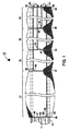
図1〜11に示されている肥満症治療装置は胃内部材11を備えている。胃内部材11は、図1と図10に示されており且つ胃管腔内の容積に取って代わるような設計とされている表面積の大きなメッシュ材料(例えば、発泡性ポリエチレンのメッシュ)であるのが好ましい。挿入された胃内部材11は、胃管腔内で十分な体積を占めていて図11に示されているように幽門1010内を通過しないようになされている。必要とされる正確な体積は、患者の胃管腔の体積に依存する患者特有のものである。一つの例においては、胃内部材11の見掛け体積は、約500mL〜約1500mLの範囲内とすることができる。ここで使用されている“見掛け体積”という用語は、胃管腔内に配備される前の胃内部材11の体積を指している。
The obesity treatment device shown in FIGS. 1 to 11 includes an intragastric member 11. The intragastric member 11 is a high surface area mesh material (eg, foamed polyethylene mesh) as shown in FIGS. 1 and 10 and designed to replace the volume in the gastric lumen. Is preferred. The inserted intragastric member 11 occupies a sufficient volume in the gastric lumen so that it does not pass through the
図1〜11を参照して説明されるように、胃内部材11の給送は、胃内部材11を、保持部材によって複数の別々の束に仕切ることによって可能にされる。該保持部材は、胃内部材11の長手方向の長さに沿って周方向に配置されている。一般的に言うと、胃内部材11を束に形成することによって、胃管腔内への制御された給送が容易になる。引っ張り紐又は結束縫合糸を使用することによって、胃管腔内への胃内部材11の配備が可能になる。結束縫合糸の遠位端はこれらの束に固定されている。結束縫合糸の各々の近位の自由端を引っ張ることによって、対応する束を給送チューブに沿って遠位方向へ進めることが可能となる。結束縫合糸は、束の各々が給送チューブから滑り出て胃管腔内へ入るまで引っ張られる。 As described with reference to FIGS. 1 to 11, feeding of the intragastric member 11 is made possible by partitioning the intragastric member 11 into a plurality of separate bundles by a holding member. The holding member is disposed in the circumferential direction along the longitudinal length of the intragastric member 11. Generally speaking, forming the intragastric member 11 in a bundle facilitates controlled delivery into the gastric lumen. The use of a pull string or tie suture allows the intragastric member 11 to be deployed within the gastric lumen. The distal end of the tie suture is secured to these bundles. By pulling the proximal free end of each of the tie sutures, the corresponding bundle can be advanced distally along the delivery tube. The tie suture is pulled until each of the bundles slides out of the delivery tube and enters the gastric lumen.
図1は、複数の別々の束に仕切られた例示的な胃内部材11を示している。胃内部材11は比較的多数の束を含むことができるけれども、簡素化及び明確化のために、4つの束のみが示されている。特に、胃内部材11の遠位部分に沿って伸長している束14、15、16、17が示されている。胃内部材11を別々の束14〜17に区分化することによって、胃管腔内への胃内部材の給送及び配備が容易になる。保持部材34、35、36、37、38は、胃内部材11の所定の長手方向長さの位置に周方向に配置されて束14〜17を形成している。各束14、15、16及び17の長手方向の長さは、変えることができ且つ必要とされる区分化の程度に部分的に依存する。束14〜17の各々の長手方向長さが短ければ短いほど、給送及び配備中の胃内部材11を操作する際の制御が増々容易になる。
FIG. 1 shows an exemplary intragastric member 11 partitioned into a plurality of separate bundles. Although intragastric member 11 may include a relatively large number of bundles, only four bundles are shown for simplicity and clarity. In particular, bundles 14, 15, 16, 17 are shown extending along the distal portion of intragastric member 11. By segmenting the intragastric member 11 into separate bundles 14-17, delivery and deployment of the intragastric member into the gastric lumen is facilitated. The holding
保持部材35は、胃内部材11の遠位端を束14と束15とに仕切っている。更に、保持部材36は胃内部材11の遠位端を束16に仕切っており、更に、保持部材37は胃内部材11を束17に仕切っている。図1に示されている付加的な保持部材34及び38は、胃内部材11を更に拘束して給送中の厚みを薄く束14と束17との端部が望ましくなく外方へ開いて給送チューブ18に対して自由に動くのを実質的に防止するために設けられている。
The holding member 35 partitions the distal end of the intragastric member 11 into a
保持部材34〜38を備えている胃内部材11が給送チューブ18を覆って取り付けられた状態で示されている。図1は、束14〜17がとびとびの間隔で給送チューブ18の周囲に拘束されていることを示している。束14〜17をこのように拘束することによって、胃内部材11を胃管腔内へ制御して給送し且つ配備することが可能になる。
The intragastric member 11 with the retaining members 34-38 is shown attached over the
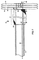
保持部材34〜38は、弾性のバンドとするか又は弾性リングのような他の構造とすることができる。保持部材34〜38は、胃内部材11に固定されており且つ実質的に相対的に動くことがない。保持部材34〜38を胃内部材11にとびとびの位置で取り付けることによって、部材11全体を胃管腔へと給送することができる厚みの薄い形態を形成することが可能になる。保持部材34〜38は、図1に示されているように胃内部材11の周りに周方向に伸長している。保持部材34〜38の各々は、それが接触する結束縫合糸の各々の遠位端に取り付けられている。一例として、図10は、保持部材38を示しており、保持部材38は、結束縫合糸64の遠位端85において結束縫合糸64に接着によって取り付けられている。保持部材38を結束縫合糸64の遠位端85に取り付けることは、保持部材38と結束縫合糸64の遠位端85との両方が、結束縫合糸64の近位端が引っ張られると遠位方向へ動くのを可能にするためには十分である。保持部材38を結束縫合糸64の遠位端85に固定する他の手段も考えられる。例えば、結束縫合糸64の遠位端85を保持部材38に結びつけても良い。別の方法として、結束縫合糸64は、保持部材38にリベットで留めるか又はかしめても良い。結束縫合糸64のメッシュの束910及び保持部材38に対する取り付けを更に確実なものとするために、結束縫合糸64はメッシュ910の網目920内へ編み込むこともできる。
The retaining members 34-38 can be elastic bands or other structures such as elastic rings. The holding
例示的な実施例においては、保持部材34〜38(図1参照)は、給送チューブ18上に固定するために胃内部材11の周りに周方向に伸長している。保持部材34〜38同士は、約10cm〜約30cmだけ隔てて胃内部材11を別々の束状構造14〜17に仕切っても良い。他の隔置距離も考えられる。
In the exemplary embodiment, retention members 34-38 (see FIG. 1) extend circumferentially about intragastric member 11 for fixation on
図1には5つの保持部材34〜38が示されているけれども、5個より多いか又は少ない保持部材を使用しても良い。使用される保持部材の個数は、給送中に望ましい胃内部材11の仕切りの程度に部分的に依存する。一般的に言うと、適切な個数の保持部材が、胃内部材11の実質的な部分が給送中に径方向及び長手方向にあちこち自由に動かないように所定の間隔で配置されなければならない。このような偶発的な動きは、部材11のサイズを大きくして胃管腔内への給送及び配備を難しくさせる。 Although five retaining members 34-38 are shown in FIG. 1, more or fewer than five retaining members may be used. The number of retaining members used will depend in part on the degree of partitioning of the intragastric member 11 desired during delivery. Generally speaking, an appropriate number of retaining members must be arranged at predetermined intervals so that a substantial portion of the intragastric member 11 does not move freely in the radial and longitudinal directions during delivery. . Such accidental movement increases the size of member 11 and makes delivery and deployment into the gastric lumen difficult.
結束縫合糸61〜64は、束14〜17に固定された状態で示されている。結束縫合糸61〜64は、引っ張り紐として示されており、該引っ張り紐は束14〜17が給送チューブ18に沿って遠位方向に進入せしめられ且つ最終的にはチューブ18が胃管腔内へ解放されるのを可能にする。結束縫合糸61は、近位端66と遠位端82とを備えている。ここで使用されている結束縫合糸の各々の遠位端は、束14〜17の外面に沿って伸長している結束縫合糸の部分を指している。ここで使用されている各結束縫合糸の近位端は、結束縫合糸における給送チューブ18の管腔内の束14〜17の内面に沿って伸長している部分を指している。遠位端82は保持部材35に固定されており、近位端66は管腔18内を近位方向に伸長している自由端である。
The binding sutures 61-64 are shown fixed to the bundles 14-17. The tie sutures 61-64 are shown as tension strings that allow the bundles 14-17 to be advanced distally along the
結束縫合糸62は、近位端67と遠位端83とを備えている。遠位端83は保持部材36に取り付けられており、近位端67は、管腔18内を近位方向に伸長している自由端である。結束縫合糸62の遠位端83はまた保持部材35に取り付けられていることは注目すべきである。
The
結束縫合糸63は近位端68と遠位端84とを備えている。遠位端84は保持部材37に固定されており、近位端68は管腔18内を近位方向に伸長している自由端である。結束縫合糸63の遠位端84はまた保持部材35及び36にも取り付けられていることは注目すべきである。
The
結束縫合糸64は近位端65と遠位端85とを備えている。遠位端85は保持部材38に取り付けられており、近位端65は管腔18内を近位方向に伸長している自由端である。結束縫合糸64の遠位端85は、保持部材35,36,37及び38に方向へ近位方向に伸長している。結束縫合糸61〜64の近位端65〜68の自由端の各々は、患者の食道の管腔18内を近位方向に伸長し且つ患者の口の外で終端していて、医師が胃内部材11の配備中に結束縫合糸61〜64へアクセスができるようにされている。
The
胃内部材11は種々の材料によって作ることができるが、図1〜11に示されているように織物ポリマーメッシュによって作られているのが好ましい。メッシュ部材11は、給送チューブ18の周囲に配置されている網目靴下状の構造に似ている。網目靴下状構造は、しなやかで且つ束状に仕切ることができる。網目靴下状構造はまた、個々の束が給送チューブ18に沿って遠位方向へ進入させることができるように流動させることもできる。好ましい実施例においては、メッシュ910(図10)は、厚みが約40〜50ミクロンの低密度ポリエチレンによって作られる。網目状構造によって作られた医療器具の詳細は、米国特許出願第11/743.732号に記載されており、該出願はこれに言及することによって本明細書に参考として組み入れられている。他のタイプの材料も考えられる。例えば、多くの公知のプラスチック、例えば、ポリエステル、ポリウレタン、ポリアミド及びシリコーンを使用することができる。哺乳動物の毛は、天然の胃石を形成することが分かっており、従ってこれもまた可能な材料である。フッ化エチレンプロピレン、エチレンビニルアセテートコポリマー、ナイロン又は生体適合性であり且つ食物が付着しない種類のポリマーも使用することができる。
The intragastric member 11 can be made of a variety of materials, but is preferably made of a woven polymer mesh as shown in FIGS. The mesh member 11 resembles a mesh sock-like structure disposed around the feeding
以上、胃内部材11の構造を説明したが、次に胃内部材11の給送及び配備方法を説明する。胃内部材11は、給送チューブ18の外周上に装填される(図1)。胃内部材11は、給送チューブ18の周りに周方向に伸長する構造とされている。保持部材34〜38は、同様に胃内部材11の周りに周方向に所定間隔で設けられて、上記したように束14〜17の仕切りを形成している。保持部材34〜38はまた胃内部材11を給送チューブ18上に拘束された薄型形状で固定する補助となる。図1に示されている実施例においては、保持部材34〜38は、給送チューブ18の遠位端に沿って約30cmの間隔で隔てて配置することができる。
The structure of the intragastric member 11 has been described above. Next, a method for feeding and deploying the intragastric member 11 will be described. The intragastric member 11 is loaded on the outer periphery of the delivery tube 18 (FIG. 1). The intragastric member 11 is configured to extend in the circumferential direction around the feeding
結束縫合糸61〜64は、束14〜17に対して長手方向にメッシュ910の網目920に通して結束縫合糸61〜64を編み合わせることによって取り付けることができる(図10)。各々の結束縫合糸61〜64の遠位端82〜85は、保持部材34〜38の下方に配置することができる。胃内部材11を給送チューブ18に固定するための種々の他の機構が考えられる。例えば、結束縫合糸61,62,63,64は、メッシュ910の網目に通して輪にするか、縫い付けるか又は突き通すことができる(図10)。近位端65〜68は自由端であり、該自由端は、給送チューブ18の管腔17を伸長し、オーバーチューブ1000(図11)を介して患者の口から出して、医師が束14〜17の配備中にアクセスできるようにしている。
The binding sutures 61 to 64 can be attached to the
胃内部材11を、保持部材34〜38及び結束縫合糸61〜64によって給送チューブ18上に装着させると、胃内部材11の給送を始めることができる。胃内部材11及び給送チューブ18は、患者の食道に沿って且つ胃管腔1020(図11)の入口内へと広がっているオーバーチューブ1000(図11)を通じて誘導される。給送チューブ18は、オーバーチューブ1000を通り胃管腔1020内へと、胃内部材11が束14〜17(図1)によって拘束された薄い形状にされた状態で誘導される。
When the intragastric member 11 is mounted on the feeding
給送チューブ18が胃管腔1020内へ導入された後に、胃内部材11の束14〜17の配備は、以下に説明するように、結束縫合糸61〜64の近位端65〜68の各々を引っ張ることによって開始される。近位端65〜68は、カラーコード化されていて、オペレーターが結束縫合糸61〜64のうちのどれが引っ張られているかを特定するのを補助する。近位端61〜64を論理的に特定し且つ組織化された構造とするための他の手段も考えられる。例えば、近位端61〜64は、ユーザーに優しい形状を形成するために巻き付けても良い。
After the
結束縫合糸61の近位端66は、(図1において矢印によって示されているように)所定の大きさの力によって引っ張って第一の束14を給送チューブ18の遠位(前方)端に向かって移動させる。第一の束14が給送チューブ18の遠位端縁に向かって動くことによって、第一の束14は、図2に示されている圧縮状態とされる。図2は、第一の束14が折り目線によって指示されるように圧縮されたことを示している。結束縫合糸61の近位端が引っ張られる所定の大きさの力及び保持部材35の弾性は、第一の束14を給送チューブ18の遠位端に圧縮された形状で維持する助けとなる。胃内部材11のメッシュ910(図10)の周囲の保持部材35の弾性によって、給送チューブ18に対する束14の十分な摩擦係合力が提供され、束14はこの結合部において給送チューブ18の遠位端から容易に摺って外れないようにされている。このような摩擦係合力は、給送チューブ18から各束14〜17を一つずつ配備する制御された配備方法が提供される。第一の束14の幅が薄くなるにつれて、結束縫合糸61の遠位端82(例えば、チューブ18の外側の部分)は幅が薄くなり、一方、結束縫合糸61(例えばチューブ18の内側の部分)の近位端66の長さはこれに対応して長くなる。
The proximal end 66 of the binding suture 61 is pulled by a predetermined amount of force (as indicated by the arrow in FIG. 1) to pull the
結束縫合糸61をその近位端66(図2)において適当な大きさの力によって更に引っ張ることによって第一の束14を給送チューブ18の遠位端から摺動させて外れさせ(図3)、束15〜17を図3に示されているように給送チューブ18に沿って配置されたままとする。図3は、束15が給送チューブ18から取り外させる次の束であることを示している。結束縫合糸62の近位端67を、(図3において矢印によって示されるように)所定の大きさによって引っ張って束15を給送チューブ18の遠位端縁に向かって動かす。束15が給送チューブ18の遠位端縁向かって移動すると、束15は図4に示されているように圧縮された状態となる。束15は、折り目線によって指示されるように圧縮されている。結束縫合糸62の近位端67が引っ張られる所定の大きさの力と保持部材36の弾性とは、第二の束15を給送チューブ18の遠位端において圧縮された形状に維持する補助となる。胃内部材11のメッシュ910(図10)の周りの保持部材36の弾性によって、給送チューブ18に対する第二の束15の十分な摩擦係合が提供され、その結果、第二の束15は、この結合部において給送チューブ18の遠位端から滑って容易に外れることがない。束15の長さが短くなるにつれて、結束縫合糸62の遠位端83(すなわち、チューブ18の外側の部分)の長さは短くなり、一方、結束縫合糸62の近位端67(チューブ18の内側の部分)の長さはこれに対応して長くなる。
The
結束縫合糸62をその近位端67を所定の大きさの力で更に引っ張ることによって、束15が給送チューブ18の遠位端から滑って外れ(図4)、それによって、図5に示されているように、束16及び17が給送チューブ18に沿って配置されたままとなる。図5は束16が給送チューブ18から取り外される次の束であることを示している。結束縫合糸63の近位端68は所定の大きさの力によって(図5において矢印で示されているように)引っ張られて図6に示されている圧縮状態となる。図6は束16が折り目線によって指示されるように圧縮されていることを示している。結束縫合糸63の近位端68が引っ張られる所定の大きさの力と保持部材37の弾性とは、第三の束16を給送チューブ18の遠位端に圧縮された形状で維持する補助となる。胃内部材11のメッシュ910(図10)の周りの保持部材37の弾性によって、給送チューブ18に対する束16の十分な摩擦係合が提供され、その結果、束16は、この結合部において給送チューブ18の遠位端から滑って容易に外れることがない。束16の長さが短くなると、結束縫合糸63の遠位端84の長さ(すなわち、チューブ18の外側の部分)は短くなり、一方、結束縫合糸63の近位端68の長さ(すなわち、チューブ18の内側の部分)はこれに対応して長くなる。
By further pulling the
結束縫合糸63をその近位端68(図6)で更に引っ張ることによって、束16は給送チューブ18の遠位端から滑って外れる(図7)。この結合部においては、束17は、給送チューブ18に沿って配置されている唯一の保持束17として図7に示されている。結束縫合糸64の近位端65は、(図7において矢印で示されているように)引っ張られて、図8に示されているように束17は圧縮状態となる。図8は束17が折り目線によって指示されるように圧縮されたことを示している。結束縫合糸64の近位端65が引っ張られる所定の大きさの力と保持部材38の弾性とは、給送チューブ18の遠位端に第四の束17を圧縮された形状に維持する補助となる。胃内部材11のメッシュ910(図10)の周りの保持部材の弾性によって、給送チューブ18に対する束17の十分な摩擦係合が提供され、その結果、束17は、この結合部において給送チューブ18の遠位端から容易に滑って外れることがない。束16の長さが短くなると、結束縫合糸64の遠位端85(すなわち、チューブ18の外側の部分)の長さは短くなり、一方、結束縫合糸64の近位端65(すなわち、チューブ18の内側の部分)の長さはこれに対応して長くなる。
By further pulling the
結束縫合糸64を近位端65(図8)において更に引っ張ると、束17は給送チューブ18の遠位端から滑って外れる(図9)。この時点で、束14〜17の全てが胃管腔1020内に配備される(図11)。結束縫合糸61〜64の各々の近位端65〜68は切断され、給送チューブ18はオーバーチューブ1000を介して取り外される(図11)。
Further pulling the
図9は、給送チューブ18から配備された束14〜17の全てを示している。ビード90〜93は、それらの各々の結束縫合糸61〜64の面に固定された状態で示されている。ビード90〜93は、それらの各々の束14〜17を長手方向に締め付け且つ束14〜17を圧縮され且つ束ねられた形状に維持するラチェット構造として機能する(図9)。束14〜17を帯状に締め付けるための他のタイプのラチェット構造も考えられ且つそのことが当業者はわかるであろう。例えば、近位及び遠位のストッパを、束14〜17を圧縮形状に維持するために使用できる。別の方法として、束14〜17の全てを結び付けるか又は相互に束ねても良い。
FIG. 9 shows all of the bundles 14-17 deployed from the
上記の給送方法は、付加的な胃内部材11を給送チューブ18の周りに装着し且つこれらの胃内部材11を束の全てが胃管腔内へ挿入されるまで既に挿入されている束14〜17に対して押し付けることによって繰り返される。付加的な胃内部材11の配備は、胃管腔内の比較的大きな置き換えが必要とされる場合になされる。
In the above delivery method, additional intragastric members 11 are mounted around the
上記の処置の代替例として、結束縫合糸64が引っ張られて束17の遠位方向への移動がなされても良い。束17が遠位方向へ移動すると束14〜16が押圧され、これらもまた遠位方向へ移動せしめられ、その結果、束14〜17は給送チューブ18の遠位端において圧縮された形状となる。
As an alternative to the above procedure, the binding
図11は、胃管腔1020内に挿入されて完全に配備された状態の胃内部材11を示している。配備された胃内部材11は、束14〜17を拘束するための如何なるストッパも無い非拘束状態で示されている。束14〜17は圧縮形状にあり、しかも、これらは幽門1010を介して出て行かないような十分な体積を占めている。ビード90〜93は、束14〜17を締め付け且つ束14〜17を圧縮された状態で胃管腔1020内に維持している。
FIG. 11 shows the intragastric member 11 inserted into the
胃内部材11は、束14〜17が、幽門1010内を通過するのを阻止する体積を胃管腔1020内に占めるほど十分に大きい。胃内部材11は、胃管腔1020内の十分大きな容積を占めて患者が食べる量を減らし且つ満腹度を達成する。
The intragastric member 11 is large enough to occupy the volume within the
上記の実施例は、大きな体積の物質を胃管腔内へ制御され且つ漸増的なやり方で給送する方法を説明している。種々の大きさの胃内袋を上記の実施例を使用して給送することができる。一つの実施例においては、約4フィート(121.9センチメートル)の長手方向の初期長さと約6インチ(15.2センチメートル)の幅とを有する胃内袋が4つの束に仕切られ、これら4つの束の各々は約1フィート(30.5センチメートル)の長さと約1インチ(2.54センチメートル)の幅とを有するようにされる。これより多くの保持部材を使用して、胃内袋を更に仕切って給送チューブ18上に組み立てられる束を薄くしても良い。束の各々は、胃管腔内に配備させた後は、幅が約6インチ(15.2センチメートル)で長手方向の長さが約1.5インチ(3.8センチメートル)である。一般的に言うと、配備される束14〜17は、給送チューブ18上に組み付けられた束14〜17の幅よりも広い。
The above example illustrates a method of delivering a large volume of material into the gastric lumen in a controlled and incremental manner. Various sizes of intragastric bags can be delivered using the embodiments described above. In one embodiment, an intragastric bag having an initial longitudinal length of about 4 feet (121.9 centimeters) and a width of about 6 inches (15.2 centimeters) is divided into four bundles; Each of these four bundles is adapted to have a length of about 1 foot (30.5 centimeters) and a width of about 1 inch (2.54 centimeters). More holding members may be used to further thin the bundle that is assembled on the
胃内部材11を胃管腔1020から取り除くためには、保持部材34〜38は、典型的には、束14〜17が非圧縮状態となり且つ管腔1020から引き出すことができるように切断される。次いで、部材11の一端が鉗子又は同様の器具によって掴まれ且つ患者から引き出される。
In order to remove the intragastric member 11 from the
本発明のここに示した実施例の種々の部材の構造又は構成の他のあらゆる開示されていない又は付随的な細部は、これらの部材がここに開示されているように行なうのに必要とされる特性を有している限り、本発明の利点を達成するのに重要であるとは考えられていない。これらの及びその他の構造の細部の選択は、本開示に鑑みた場合に、この技術分野の初歩技術者でさえ、その能力の範囲内に十分に含まれるものであると考えられる。以上、本発明の例示的な実施例を、実際的な作動構造を開示するためにかなり詳細に説明して本発明を有利に実施することができるようにした。ここに記載された設計は例示的なものであることだけを意図している。本発明による新規な特徴は、本発明の精神及び範囲から逸脱することなく他の構造的な形態で組み込むことができる。 Any other undisclosed or attendant details of the structure or construction of the various members of the presently illustrated embodiments of the invention are required to make these members as disclosed herein. As long as it has the following characteristics, it is not considered important to achieve the advantages of the present invention. Selection of these and other structural details are considered well within the capability of even the novice engineer of this field in view of the present disclosure. The exemplary embodiments of the present invention have been described in considerable detail in order to disclose practical working structures so that the present invention may be advantageously practiced. The design described herein is intended to be exemplary only. The novel features according to the invention can be incorporated in other structural forms without departing from the spirit and scope of the invention.
11 胃内部材、
14〜17 束、
18 給送チューブ、
34〜38 保持部材、
61〜64 結束縫合糸、
65〜68 近位端、
82〜85 遠位端、
90〜93 ビード、
910 メッシュ、
920 網目、
1000 オーバーチューブ、
1010 幽門、
1020 胃管腔
11 Intragastric members,
14-17 bundles,
18 Feeding tube,
34 to 38 holding member,
61-64 Tying suture,
65-68 proximal end,
82-85 distal end,
90-93 beads,
910 mesh,
920 mesh,
1000 overtube,
1010 Pylor,
1020 Gastric lumen
Claims (7)
前記管腔内を通される第一の結束縫合糸であって、前記胃内部材の前記近位端から近位方向に延ばされて第一の自由端となる第一の近位端、及び、前記胃内部材の遠位端で前記胃内部材の外側に折り返されて前記第一の保持部材に固定される第一の遠位端、を有する第一の結束縫合糸と、
前記管腔内を通される第二の結束縫合糸であって、前記胃内部材の前記近位端から近位方向に延ばされて第二の自由端となる第二の近位端、及び前記胃内部材の前記遠位端で前記胃内部材の外側に折り返されて前記第二の保持部材に固定される第二の遠位端、を有する第二の結束縫合糸と、を備えている胃内器具であり、
前記第一及び第二の束は、それぞれ、該環状の材料の長手軸線方向に伸長した形態と長手軸線方向に収縮した形態との間で動作可能であり、
前記第一及び第二の保持部材がそれぞれ前記胃内部材の前記近位端から近位方向に延された状態の前記第一の近位端及び第二の近位端を近位方向に引っ張ることにより遠位方向に変位可能であり、それにより前記第一の束及び第二の束を前記収縮した形態にすることができるようにされ、
前記第一の結束縫合糸は第一のラチェット部材を備えており、前記第二の結束縫合糸は第二のラチェット部材を備えており、該第一のラチェット部材と第二のラチェット部材とは、それぞれ、前記第一の束と第二の束とを前記収縮した形態に固定保持するようになされている、胃内器具。 A first material extending from the distal end toward the proximal end , the tubular material having a proximal end and a distal end and having a lumen extending between the proximal end and the distal end ; a bundle, and a second bundle which is disposed on the proximal side of the first bundle, and the first holding member disposed between said first beam and a second beam, the second has a second retaining member disposed on the proximal side of the bundle, first and second bundle forms the lumen extending in the circumferential direction, and the intragastric member,
A first tie suture passed through the lumen, the first proximal end extending proximally from the proximal end of the intragastric member to become a first free end; And a first tie suture having a first distal end that is folded outwardly of the intragastric member at the distal end of the intragastric member and secured to the first retaining member;
A second tie suture passed through the lumen, the second proximal end extending proximally from the proximal end of the intragastric member to become a second free end; And a second tie suture having a second distal end that is folded outwardly of the intragastric member at the distal end of the intragastric member and secured to the second retaining member. Is an intragastric device,
The first and second bundles are each operable between a longitudinally elongated configuration and a longitudinally contracted configuration of the annular material;
Pulling the first and second proximal ends proximally with the first and second retaining members extending proximally from the proximal end of the intragastric member, respectively Displaceable in a distal direction, whereby the first bundle and the second bundle can be brought into the contracted configuration,
The first binding suture includes a first ratchet member, and the second binding suture includes a second ratchet member. The first ratchet member and the second ratchet member , respectively, said first beam and a second and a bundle have been made to secure hold to the contracted configuration, intragastric device.
前記給送チューブの外周の周りに設けられ該給送チューブの長手方向に摺動可能された管状のシート状材料からなる胃内部材であって、第一の束と、該第一の束の近位側に配置されている第二の束と、該第一の束と第二の束との間に配置された第一の保持部材と、前記第二の束の近位側に配置された第二の保持部材とを有しており、該第1及び第2の束は周方向に延びている、胃内部材と、
前記給送チューブの前記管腔内を通される第一の結束縫合糸であって、前記給送チューブの前記近位端から近位方向に延ばされて第一の自由端となる第一の近位端、及び、前記給送チューブの遠位端で前記給送チューブの外側に折り返されて前記胃内部材の遠位端を越えて近位方向に延ばされ前記第一の保持部材に固定されている第一の遠位端、を有する第一の結束縫合糸と、
前記給送チューブの前記管腔内を通される第二の結束縫合糸であって、前記給送チューブの前記近位端から近位方向に延ばされて第二の自由端となる第二の近位端、及び、前記給送チューブの遠位端で前記給送チューブの外側に折り返されて前記胃内部材の遠位端の外側を近位方向に延ばされ前記第二の保持部材に固定されている第二の遠位端、を有する第二の結束縫合糸と、
を備えている胃内器具であり、
前記第一及び第二の保持部材が、それぞれ前記第一の近位端及び第二の近位端を近位方向に引っ張ることにより遠位方向に変位し、それにより前記第一の束及び第二の束を前記収縮した形態にするようにされ、
前記第一の結束縫合糸は第一のラチェット部材を備えており、前記第二の結束縫合糸は第二のラチェット部材を備えており、該第一のラチェット部材と第二のラチェット部材とは、前記第一の束と第二の束とを前記収縮した形態に固定保持するようになされている、
胃内器具。 A proximal end, a distal end, and the feeding tube and a lumen extending between the proximal and distal ends,
An intragastric member made of a tubular sheet-like material provided around the outer periphery of the feeding tube and slidable in the longitudinal direction of the feeding tube, wherein the first bundle and the first bundle A second bundle disposed proximally, a first holding member disposed between the first bundle and the second bundle, and disposed proximally of the second bundle. A second holding member, and the first and second bundles extend in the circumferential direction ;
A first suture tie that is passed through the tube lumen of the feeding tube, the first comprising a first free end is extended proximally from the proximal end of the delivery tube A proximal end of the first tube and a distal end of the delivery tube that is folded outwardly of the delivery tube and extends proximally beyond the distal end of the intragastric member. A first tying suture having a first distal end secured to the
A second binding suture threaded through the lumen of the delivery tube and extending in a proximal direction from the proximal end of the delivery tube to become a second free end A proximal end of the gastric tube and a distal end of the delivery tube that is folded outwardly of the delivery tube and extends outwardly of the distal end of the intragastric member in the proximal direction, the second holding member A second tying suture having a second distal end secured to the
An intragastric device comprising:
The first and second retaining members are displaced in the distal direction by pulling the first proximal end and the second proximal end in the proximal direction, respectively, whereby the first bundle and the second The second bundle is in the contracted form,
The first binding suture includes a first ratchet member, and the second binding suture includes a second ratchet member. The first ratchet member and the second ratchet member The first bundle and the second bundle are fixedly held in the contracted form.
Intragastric device.
The intragastric device according to claim 6 , wherein the first and second bundles are in the compressed configuration when slid from the delivery tube and removed.
Applications Claiming Priority (3)
| Application Number | Priority Date | Filing Date | Title |
|---|---|---|---|
| US11/963,577 | 2007-12-21 | ||
| US11/963,577 US7883524B2 (en) | 2007-12-21 | 2007-12-21 | Method of delivering an intragastric device for treating obesity |
| PCT/US2008/087007 WO2009085764A1 (en) | 2007-12-21 | 2008-12-16 | An intragastric device |
Publications (3)
| Publication Number | Publication Date |
|---|---|
| JP2011507614A JP2011507614A (en) | 2011-03-10 |
| JP2011507614A5 JP2011507614A5 (en) | 2012-02-09 |
| JP5469611B2 true JP5469611B2 (en) | 2014-04-16 |
Family
ID=40429949
Family Applications (1)
| Application Number | Title | Priority Date | Filing Date |
|---|---|---|---|
| JP2010539707A Active JP5469611B2 (en) | 2007-12-21 | 2008-12-16 | Gastric appliance |
Country Status (6)
| Country | Link |
|---|---|
| US (1) | US7883524B2 (en) |
| EP (1) | EP2222256B1 (en) |
| JP (1) | JP5469611B2 (en) |
| AU (1) | AU2008343346B2 (en) |
| CA (1) | CA2709949C (en) |
| WO (1) | WO2009085764A1 (en) |
Families Citing this family (22)
| Publication number | Priority date | Publication date | Assignee | Title |
|---|---|---|---|---|
| WO2014082044A1 (en) | 2012-11-26 | 2014-05-30 | Spatz Fgia, Inc. | System and methods for internalization of components of an adjustable intragastric balloon |
| US9974680B2 (en) | 2004-12-27 | 2018-05-22 | Spatz Fgia, Inc. | System and methods for internalization of external components of adjustable intragastric balloon |
| WO2007110866A2 (en) * | 2006-03-28 | 2007-10-04 | Spatz-Fgia Inc | Floating gastrointestinal anchor |
| CN102387762B (en) | 2009-04-03 | 2014-08-06 | 美特默迪克斯公司 | Modular gastrointestinal prostheses |
| US8702641B2 (en) | 2009-04-03 | 2014-04-22 | Metamodix, Inc. | Gastrointestinal prostheses having partial bypass configurations |
| US9173760B2 (en) | 2009-04-03 | 2015-11-03 | Metamodix, Inc. | Delivery devices and methods for gastrointestinal implants |
| US9278019B2 (en) | 2009-04-03 | 2016-03-08 | Metamodix, Inc | Anchors and methods for intestinal bypass sleeves |
| IN2012DN00316A (en) | 2009-07-10 | 2015-05-08 | Metamodix Inc | |
| WO2011045785A1 (en) * | 2009-10-13 | 2011-04-21 | Spatz Fgia, Inc. | Balloon hydraulic and gaseous expansion system |
| US9526648B2 (en) | 2010-06-13 | 2016-12-27 | Synerz Medical, Inc. | Intragastric device for treating obesity |
| US8628554B2 (en) | 2010-06-13 | 2014-01-14 | Virender K. Sharma | Intragastric device for treating obesity |
| US10420665B2 (en) | 2010-06-13 | 2019-09-24 | W. L. Gore & Associates, Inc. | Intragastric device for treating obesity |
| US10010439B2 (en) | 2010-06-13 | 2018-07-03 | Synerz Medical, Inc. | Intragastric device for treating obesity |
| US20120089170A1 (en) * | 2010-10-11 | 2012-04-12 | Allergan, Inc. | Intragastric balloon geometries |
| US8814025B2 (en) * | 2011-09-15 | 2014-08-26 | Ethicon Endo-Surgery, Inc. | Fibrin pad matrix with suspended heat activated beads of adhesive |
| US10159699B2 (en) | 2013-01-15 | 2018-12-25 | Metamodix, Inc. | System and method for affecting intestinal microbial flora |
| US9918863B2 (en) | 2013-11-13 | 2018-03-20 | Covidien Lp | Steerable gastric calibration tube |
| US9775735B2 (en) | 2014-01-31 | 2017-10-03 | Covidien Lp | Gastric calibration tube |
| US9622897B1 (en) | 2016-03-03 | 2017-04-18 | Metamodix, Inc. | Pyloric anchors and methods for intestinal bypass sleeves |
| US10779980B2 (en) | 2016-04-27 | 2020-09-22 | Synerz Medical, Inc. | Intragastric device for treating obesity |
| KR102473258B1 (en) | 2016-05-19 | 2022-12-01 | 메타모딕스, 인코포레이티드 | Pyloric Anchor Recovery Tools and Methods |
| US10893966B2 (en) | 2017-02-09 | 2021-01-19 | Spatz FGIA Ltd | Check valve with docking station for gastrointestinal balloon |
Family Cites Families (113)
| Publication number | Priority date | Publication date | Assignee | Title |
|---|---|---|---|---|
| US2508690A (en) | 1948-07-13 | 1950-05-23 | Schmerl Egon Fritz | Gastrointestinal tube |
| US4133315A (en) | 1976-12-27 | 1979-01-09 | Berman Edward J | Method and apparatus for reducing obesity |
| US4315509A (en) | 1977-01-10 | 1982-02-16 | Smit Julie A | Insertion and removal catheters and intestinal tubes for restricting absorption |
| US4134405A (en) | 1977-01-10 | 1979-01-16 | Smit Julie A | Catheter and intestine tube and method of using the same |
| US4246893A (en) | 1978-07-05 | 1981-01-27 | Daniel Berson | Inflatable gastric device for treating obesity |
| US4416267A (en) | 1981-12-10 | 1983-11-22 | Garren Lloyd R | Method and apparatus for treating obesity |
| US4899747A (en) | 1981-12-10 | 1990-02-13 | Garren Lloyd R | Method and appartus for treating obesity |
| US4403604A (en) | 1982-05-13 | 1983-09-13 | Wilkinson Lawrence H | Gastric pouch |
| US4485805A (en) | 1982-08-24 | 1984-12-04 | Gunther Pacific Limited Of Hong Kong | Weight loss device and method |
| US4558699A (en) | 1983-01-03 | 1985-12-17 | Bashour Samuel B | Method of and apparatus for restricting the passage of food through the stomach |
| US4607618A (en) | 1983-02-23 | 1986-08-26 | Angelchik Jean P | Method for treatment of morbid obesity |
| US4952339A (en) | 1985-03-22 | 1990-08-28 | Nuclear Packaging, Inc. | Dewatering nuclear wastes |
| US4723547A (en) | 1985-05-07 | 1988-02-09 | C. R. Bard, Inc. | Anti-obesity balloon placement system |
| US4696288A (en) | 1985-08-14 | 1987-09-29 | Kuzmak Lubomyr I | Calibrating apparatus and method of using same for gastric banding surgery |
| US4694827A (en) | 1986-01-14 | 1987-09-22 | Weiner Brian C | Inflatable gastric device for treating obesity and method of using the same |
| GB8603099D0 (en) | 1986-02-07 | 1986-03-12 | Blass K G | Gastrointestinal module |
| US4803985A (en) | 1986-02-14 | 1989-02-14 | Hill Carl W | Gastroplasty method |
| WO1990000376A1 (en) | 1988-07-05 | 1990-01-25 | Cantenys Jose | Intragastric balloon |
| US4925446A (en) | 1988-07-06 | 1990-05-15 | Transpharm Group Inc. | Removable inflatable intragastrointestinal device for delivering beneficial agents |
| US5234454A (en) | 1991-08-05 | 1993-08-10 | Akron City Hospital | Percutaneous intragastric balloon catheter and method for controlling body weight therewith |
| US5246456A (en) | 1992-06-08 | 1993-09-21 | Wilkinson Lawrence H | Fenestrated gastric pouch |
| US5345949A (en) | 1992-09-02 | 1994-09-13 | Shlain Leonard M | Methods for use in surgical gastroplastic procedure |
| US5327914A (en) | 1992-09-02 | 1994-07-12 | Shlain Leonard M | Method and devices for use in surgical gastroplastic procedure |
| US5306300A (en) | 1992-09-22 | 1994-04-26 | Berry H Lee | Tubular digestive screen |
| US6348056B1 (en) | 1999-08-06 | 2002-02-19 | Scimed Life Systems, Inc. | Medical retrieval device with releasable retrieval basket |
| US5938669A (en) | 1997-05-07 | 1999-08-17 | Klasamed S.A. | Adjustable gastric banding device for contracting a patient's stomach |
| US5868141A (en) | 1997-05-14 | 1999-02-09 | Ellias; Yakub A. | Endoscopic stomach insert for treating obesity and method for use |
| DE19739031A1 (en) | 1997-09-05 | 1999-03-11 | Suwelack Nachf Dr Otto | Oral administration agent, its preparation and use |
| US5993473A (en) | 1997-11-19 | 1999-11-30 | Chan; Yung C. | Expandable body device for the gastric cavity and method |
| AU756080B2 (en) * | 1998-06-04 | 2003-01-02 | New York University | Endovascular thin film devices and methods for treating and preventing stroke |
| US6067991A (en) | 1998-08-13 | 2000-05-30 | Forsell; Peter | Mechanical food intake restriction device |
| US6210347B1 (en) | 1998-08-13 | 2001-04-03 | Peter Forsell | Remote control food intake restriction device |
| US6460543B1 (en) | 1998-08-13 | 2002-10-08 | Obtech Medical Ag | Non-injection port food intake restriction device |
| US6366814B1 (en) | 1998-10-26 | 2002-04-02 | Birinder R. Boveja | External stimulator for adjunct (add-on) treatment for neurological, neuropsychiatric, and urological disorders |
| US6427089B1 (en) | 1999-02-19 | 2002-07-30 | Edward W. Knowlton | Stomach treatment apparatus and method |
| IL129032A (en) | 1999-03-17 | 2006-12-31 | Moshe Dudai | Gastric band |
| WO2001012078A1 (en) | 1999-08-12 | 2001-02-22 | Potencia Medical Ag | Stoma opening forming apparatus |
| US6454699B1 (en) | 2000-02-11 | 2002-09-24 | Obtech Medical Ag | Food intake restriction with controlled wireless energy supply |
| FR2802407B1 (en) | 1999-12-21 | 2002-12-13 | Rc Medical | DESERRABLE GASTROPLASTY RING |
| FR2804011B1 (en) | 2000-01-20 | 2002-07-19 | Rc Medical | SINGLE CONTROL GASTROPLASTY RING |
| US6450946B1 (en) | 2000-02-11 | 2002-09-17 | Obtech Medical Ag | Food intake restriction with wireless energy transfer |
| FR2805986B1 (en) | 2000-03-13 | 2002-10-11 | Districlass Madical | INTRA-GASTRIC DEVICE WITH VARIABLE VOLUME |
| FR2808674B1 (en) | 2000-05-12 | 2002-08-02 | Cie Euro Etude Rech Paroscopie | GASTROPLASTY RING WITH GRIPPED LEGS |
| US6540789B1 (en) | 2000-06-15 | 2003-04-01 | Scimed Life Systems, Inc. | Method for treating morbid obesity |
| US7033373B2 (en) | 2000-11-03 | 2006-04-25 | Satiety, Inc. | Method and device for use in minimally invasive placement of space-occupying intragastric devices |
| US20060206160A1 (en) | 2000-11-15 | 2006-09-14 | Transneuronix, Inc. | Process and electrostimulation device for treating obesity and/or gastroesophageal reflux disease |
| ES2240479T3 (en) | 2001-03-09 | 2005-10-16 | Jose Rafael Garza Alvarez | INTRAGASTRIC BALL SET. |
| JP4255286B2 (en) * | 2001-05-17 | 2009-04-15 | ウィルソン−クック メディカル インコーポレイテッド | Intragastric device for treating obesity |
| WO2002096325A1 (en) | 2001-05-27 | 2002-12-05 | Schurr Marc O | Medical implant |
| US6558400B2 (en) | 2001-05-30 | 2003-05-06 | Satiety, Inc. | Obesity treatment tools and methods |
| US20020188354A1 (en) | 2001-06-12 | 2002-12-12 | Peghini Paolo Lino | Device to treat obesity by obstructing gastric outlet |
| US6511490B2 (en) | 2001-06-22 | 2003-01-28 | Antoine Jean Henri Robert | Gastric banding device and method |
| US6627206B2 (en) | 2001-07-25 | 2003-09-30 | Greg A. Lloyd | Method and apparatus for treating obesity and for delivering time-released medicaments |
| US20040117031A1 (en) | 2001-08-27 | 2004-06-17 | Stack Richard S. | Satiation devices and methods |
| US7097665B2 (en) | 2003-01-16 | 2006-08-29 | Synecor, Llc | Positioning tools and methods for implanting medical devices |
| US6845776B2 (en) | 2001-08-27 | 2005-01-25 | Richard S. Stack | Satiation devices and methods |
| US6675809B2 (en) | 2001-08-27 | 2004-01-13 | Richard S. Stack | Satiation devices and methods |
| US6740121B2 (en) | 2001-11-09 | 2004-05-25 | Boston Scientific Corporation | Intragastric stent for duodenum bypass |
| US6755869B2 (en) | 2001-11-09 | 2004-06-29 | Boston Scientific Corporation | Intragastric prosthesis for the treatment of morbid obesity |
| US6733512B2 (en) | 2002-03-07 | 2004-05-11 | Mcghan Jim J. | Self-deflating intragastric balloon |
| US7146984B2 (en) | 2002-04-08 | 2006-12-12 | Synecor, Llc | Method and apparatus for modifying the exit orifice of a satiation pouch |
| WO2003094785A1 (en) | 2002-05-09 | 2003-11-20 | Egan Thomas D | Gastric bypass prosthesis |
| US20040019388A1 (en) | 2002-07-24 | 2004-01-29 | Starkebaum Warren L. | Methods and implants for retarding stomach emptying to treat eating disorders |
| US6746460B2 (en) | 2002-08-07 | 2004-06-08 | Satiety, Inc. | Intra-gastric fastening devices |
| US7338433B2 (en) | 2002-08-13 | 2008-03-04 | Allergan, Inc. | Remotely adjustable gastric banding method |
| US7211114B2 (en) | 2002-08-26 | 2007-05-01 | The Trustees Of Columbia University In The City Of New York | Endoscopic gastric bypass |
| DK1553878T3 (en) | 2002-08-28 | 2010-05-31 | Allergan Inc | Fatigue resistant gastric banding device |
| US7214233B2 (en) | 2002-08-30 | 2007-05-08 | Satiety, Inc. | Methods and devices for maintaining a space occupying device in a relatively fixed location within a stomach |
| US6981978B2 (en) | 2002-08-30 | 2006-01-03 | Satiety, Inc. | Methods and devices for maintaining a space occupying device in a relatively fixed location within a stomach |
| US7033384B2 (en) | 2002-08-30 | 2006-04-25 | Satiety, Inc. | Stented anchoring of gastric space-occupying devices |
| US7220237B2 (en) | 2002-10-23 | 2007-05-22 | Satiety, Inc. | Method and device for use in endoscopic organ procedures |
| US7229428B2 (en) | 2002-10-23 | 2007-06-12 | Satiety, Inc. | Method and device for use in endoscopic organ procedures |
| US7794447B2 (en) | 2002-11-01 | 2010-09-14 | Valentx, Inc. | Gastrointestinal sleeve device and methods for treatment of morbid obesity |
| US7837669B2 (en) | 2002-11-01 | 2010-11-23 | Valentx, Inc. | Devices and methods for endolumenal gastrointestinal bypass |
| US7037344B2 (en) | 2002-11-01 | 2006-05-02 | Valentx, Inc. | Apparatus and methods for treatment of morbid obesity |
| US9060844B2 (en) | 2002-11-01 | 2015-06-23 | Valentx, Inc. | Apparatus and methods for treatment of morbid obesity |
| US20090149871A9 (en) | 2002-11-01 | 2009-06-11 | Jonathan Kagan | Devices and methods for treating morbid obesity |
| US6656194B1 (en) | 2002-11-05 | 2003-12-02 | Satiety, Inc. | Magnetic anchoring devices |
| US7695446B2 (en) | 2002-12-02 | 2010-04-13 | Gi Dynamics, Inc. | Methods of treatment using a bariatric sleeve |
| US7037343B2 (en) | 2002-12-23 | 2006-05-02 | Python, Inc. | Stomach prosthesis |
| US20040143342A1 (en) | 2003-01-16 | 2004-07-22 | Stack Richard S. | Satiation pouches and methods of use |
| US20060015151A1 (en) | 2003-03-14 | 2006-01-19 | Aldrich William N | Method of using endoscopic truncal vagoscopy with gastric bypass, gastric banding and other procedures |
| US7291160B2 (en) | 2003-03-17 | 2007-11-06 | Delegge Rebecca | Intragastric catheter |
| US6981980B2 (en) | 2003-03-19 | 2006-01-03 | Phagia Technology | Self-inflating intragastric volume-occupying device |
| US20040220682A1 (en) | 2003-03-28 | 2004-11-04 | Gi Dynamics, Inc. | Anti-obesity devices |
| US7175638B2 (en) | 2003-04-16 | 2007-02-13 | Satiety, Inc. | Method and devices for modifying the function of a body organ |
| US20060074450A1 (en) | 2003-05-11 | 2006-04-06 | Boveja Birinder R | System for providing electrical pulses to nerve and/or muscle using an implanted stimulator |
| US7731757B2 (en) | 2003-06-01 | 2010-06-08 | Reflux Corporation | Obesity treatment |
| US7309341B2 (en) | 2003-09-30 | 2007-12-18 | Ethicon Endo-Surgery, Inc. | Single lumen anastomosis applier for self-deploying fastener |
| US7054690B2 (en) | 2003-10-22 | 2006-05-30 | Intrapace, Inc. | Gastrointestinal stimulation device |
| US7177693B2 (en) | 2004-01-07 | 2007-02-13 | Medtronic, Inc. | Gastric stimulation for altered perception to treat obesity |
| US20050149142A1 (en) | 2004-01-07 | 2005-07-07 | Starkebaum Warren L. | Gastric stimulation responsive to sensing feedback |
| US7931693B2 (en) | 2004-02-26 | 2011-04-26 | Endosphere, Inc. | Method and apparatus for reducing obesity |
| US20050209653A1 (en) | 2004-03-16 | 2005-09-22 | Medtronic, Inc. | Intra-luminal device for gastrointestinal electrical stimulation |
| WO2006049725A2 (en) | 2004-03-23 | 2006-05-11 | Minimus Surgical Systems | Surgical systems and devices to enhance gastric restriction therapies |
| US20050222637A1 (en) | 2004-03-30 | 2005-10-06 | Transneuronix, Inc. | Tachygastrial electrical stimulation |
| US20050222638A1 (en) | 2004-03-30 | 2005-10-06 | Steve Foley | Sensor based gastrointestinal electrical stimulation for the treatment of obesity or motility disorders |
| US20050246037A1 (en) | 2004-04-30 | 2005-11-03 | Medtronic, Inc. | Partial esophageal obstruction to limit food intake for treatment of obesity |
| US20050245957A1 (en) | 2004-04-30 | 2005-11-03 | Medtronic, Inc. | Biasing stretch receptors in stomach wall to treat obesity |
| WO2005110280A2 (en) | 2004-05-07 | 2005-11-24 | Valentx, Inc. | Devices and methods for attaching an endolumenal gastrointestinal implant |
| US7112186B2 (en) | 2004-05-26 | 2006-09-26 | Shah Tilak M | Gastro-occlusive device |
| JP4324535B2 (en) * | 2004-09-28 | 2009-09-02 | 朝日インテック株式会社 | Medical treatment tool |
| ATE552806T1 (en) | 2004-12-09 | 2012-04-15 | Ami Gmbh | GASTRIC BAND TO TREAT OBESITY |
| US20060257445A1 (en) | 2005-04-29 | 2006-11-16 | Medtronic, Inc. | Devices for augmentation of lumen walls |
| US20060257444A1 (en) | 2005-04-29 | 2006-11-16 | Medtronic, Inc. | Devices for augmentation of lumen walls |
| US7984717B2 (en) | 2005-04-29 | 2011-07-26 | Medtronic, Inc. | Devices for augmentation of lumen walls |
| US7674271B2 (en) | 2005-05-04 | 2010-03-09 | InTailor Surgical, Inc. | Endoluminal gastric ring and method |
| JP4996598B2 (en) * | 2005-05-09 | 2012-08-08 | クック メディカル テクノロジーズ エルエルシー | Intragastric device for the treatment of obesity |
| US20050240239A1 (en) | 2005-06-29 | 2005-10-27 | Boveja Birinder R | Method and system for gastric ablation and gastric pacing to provide therapy for obesity, motility disorders, or to induce weight loss |
| US8951285B2 (en) * | 2005-07-05 | 2015-02-10 | Mitralign, Inc. | Tissue anchor, anchoring system and methods of using the same |
| US7871416B2 (en) | 2005-07-22 | 2011-01-18 | Phillips Edward H | Clamp device to plicate the stomach |
| AU2006331503B2 (en) * | 2005-12-22 | 2012-09-06 | Cook Medical Technologies Llc | Coiled intragastric member for treating obesity |
| WO2007136468A2 (en) | 2006-04-07 | 2007-11-29 | Valentx, Inc. | Devices and methods for endolumenal gastrointestinal bypass |
-
2007
- 2007-12-21 US US11/963,577 patent/US7883524B2/en active Active
-
2008
- 2008-12-16 EP EP08866522A patent/EP2222256B1/en active Active
- 2008-12-16 WO PCT/US2008/087007 patent/WO2009085764A1/en active Application Filing
- 2008-12-16 JP JP2010539707A patent/JP5469611B2/en active Active
- 2008-12-16 AU AU2008343346A patent/AU2008343346B2/en active Active
- 2008-12-16 CA CA2709949A patent/CA2709949C/en active Active
Also Published As
| Publication number | Publication date |
|---|---|
| CA2709949A1 (en) | 2009-07-09 |
| EP2222256A1 (en) | 2010-09-01 |
| US20090164028A1 (en) | 2009-06-25 |
| US7883524B2 (en) | 2011-02-08 |
| WO2009085764A1 (en) | 2009-07-09 |
| AU2008343346B2 (en) | 2013-04-18 |
| AU2008343346A1 (en) | 2009-07-09 |
| JP2011507614A (en) | 2011-03-10 |
| EP2222256B1 (en) | 2012-10-10 |
| CA2709949C (en) | 2012-09-25 |
Similar Documents
| Publication | Publication Date | Title |
|---|---|---|
| JP5469611B2 (en) | Gastric appliance | |
| JP5276117B2 (en) | Intragastric bag feeder | |
| JP4255286B2 (en) | Intragastric device for treating obesity | |
| JP4996598B2 (en) | Intragastric device for the treatment of obesity | |
| JP5024902B2 (en) | Stomach bag for treating obesity | |
| JP5021675B2 (en) | Coil-like intragastric member for the treatment of obesity | |
| AU2002305631A1 (en) | Intragastric device for treating obesity |
Legal Events
| Date | Code | Title | Description |
|---|---|---|---|
| A521 | Request for written amendment filed |
Free format text: JAPANESE INTERMEDIATE CODE: A523 Effective date: 20111213 |
|
| A621 | Written request for application examination |
Free format text: JAPANESE INTERMEDIATE CODE: A621 Effective date: 20111213 |
|
| A711 | Notification of change in applicant |
Free format text: JAPANESE INTERMEDIATE CODE: A711 Effective date: 20120203 |
|
| A977 | Report on retrieval |
Free format text: JAPANESE INTERMEDIATE CODE: A971007 Effective date: 20130218 |
|
| A131 | Notification of reasons for refusal |
Free format text: JAPANESE INTERMEDIATE CODE: A131 Effective date: 20130312 |
|
| A601 | Written request for extension of time |
Free format text: JAPANESE INTERMEDIATE CODE: A601 Effective date: 20130612 |
|
| A602 | Written permission of extension of time |
Free format text: JAPANESE INTERMEDIATE CODE: A602 Effective date: 20130619 |
|
| A601 | Written request for extension of time |
Free format text: JAPANESE INTERMEDIATE CODE: A601 Effective date: 20130712 |
|
| A602 | Written permission of extension of time |
Free format text: JAPANESE INTERMEDIATE CODE: A602 Effective date: 20130722 |
|
| A521 | Request for written amendment filed |
Free format text: JAPANESE INTERMEDIATE CODE: A523 Effective date: 20130812 |
|
| TRDD | Decision of grant or rejection written | ||
| A01 | Written decision to grant a patent or to grant a registration (utility model) |
Free format text: JAPANESE INTERMEDIATE CODE: A01 Effective date: 20140114 |
|
| A61 | First payment of annual fees (during grant procedure) |
Free format text: JAPANESE INTERMEDIATE CODE: A61 Effective date: 20140131 |
|
| R150 | Certificate of patent or registration of utility model |
Ref document number: 5469611 Country of ref document: JP Free format text: JAPANESE INTERMEDIATE CODE: R150 Free format text: JAPANESE INTERMEDIATE CODE: R150 |
|
| R250 | Receipt of annual fees |
Free format text: JAPANESE INTERMEDIATE CODE: R250 |
|
| R250 | Receipt of annual fees |
Free format text: JAPANESE INTERMEDIATE CODE: R250 |
|
| R250 | Receipt of annual fees |
Free format text: JAPANESE INTERMEDIATE CODE: R250 |
|
| R250 | Receipt of annual fees |
Free format text: JAPANESE INTERMEDIATE CODE: R250 |
|
| R250 | Receipt of annual fees |
Free format text: JAPANESE INTERMEDIATE CODE: R250 |
|
| R250 | Receipt of annual fees |
Free format text: JAPANESE INTERMEDIATE CODE: R250 |
|
| R250 | Receipt of annual fees |
Free format text: JAPANESE INTERMEDIATE CODE: R250 |