JP5468459B2 - Grinder - Google Patents
Grinder Download PDFInfo
- Publication number
- JP5468459B2 JP5468459B2 JP2010107501A JP2010107501A JP5468459B2 JP 5468459 B2 JP5468459 B2 JP 5468459B2 JP 2010107501 A JP2010107501 A JP 2010107501A JP 2010107501 A JP2010107501 A JP 2010107501A JP 5468459 B2 JP5468459 B2 JP 5468459B2
- Authority
- JP
- Japan
- Prior art keywords
- controller
- switch block
- terminal
- switch
- assembly
- Prior art date
- Legal status (The legal status is an assumption and is not a legal conclusion. Google has not performed a legal analysis and makes no representation as to the accuracy of the status listed.)
- Active
Links
- 238000003780 insertion Methods 0.000 claims description 15
- 230000037431 insertion Effects 0.000 claims description 14
- 230000015572 biosynthetic process Effects 0.000 claims description 5
- 239000000428 dust Substances 0.000 description 4
- 230000000903 blocking effect Effects 0.000 description 3
- 230000000694 effects Effects 0.000 description 3
- 230000003014 reinforcing effect Effects 0.000 description 3
- XEEYBQQBJWHFJM-UHFFFAOYSA-N Iron Chemical compound [Fe] XEEYBQQBJWHFJM-UHFFFAOYSA-N 0.000 description 2
- 230000005540 biological transmission Effects 0.000 description 2
- 230000004048 modification Effects 0.000 description 2
- 238000012986 modification Methods 0.000 description 2
- 238000005192 partition Methods 0.000 description 2
- 239000000758 substrate Substances 0.000 description 2
- 238000001816 cooling Methods 0.000 description 1
- WABPQHHGFIMREM-UHFFFAOYSA-N lead(0) Chemical compound [Pb] WABPQHHGFIMREM-UHFFFAOYSA-N 0.000 description 1
- 239000000463 material Substances 0.000 description 1
- 239000002184 metal Substances 0.000 description 1
- 229910052751 metal Inorganic materials 0.000 description 1
- 230000000149 penetrating effect Effects 0.000 description 1
- 238000005498 polishing Methods 0.000 description 1
- 230000000717 retained effect Effects 0.000 description 1
- 229920003002 synthetic resin Polymers 0.000 description 1
- 239000000057 synthetic resin Substances 0.000 description 1
Images


Classifications
-
- B—PERFORMING OPERATIONS; TRANSPORTING
- B24—GRINDING; POLISHING
- B24B—MACHINES, DEVICES, OR PROCESSES FOR GRINDING OR POLISHING; DRESSING OR CONDITIONING OF ABRADING SURFACES; FEEDING OF GRINDING, POLISHING, OR LAPPING AGENTS
- B24B23/00—Portable grinding machines, e.g. hand-guided; Accessories therefor
- B24B23/02—Portable grinding machines, e.g. hand-guided; Accessories therefor with rotating grinding tools; Accessories therefor
- B24B23/028—Angle tools
-
- B—PERFORMING OPERATIONS; TRANSPORTING
- B24—GRINDING; POLISHING
- B24B—MACHINES, DEVICES, OR PROCESSES FOR GRINDING OR POLISHING; DRESSING OR CONDITIONING OF ABRADING SURFACES; FEEDING OF GRINDING, POLISHING, OR LAPPING AGENTS
- B24B55/00—Safety devices for grinding or polishing machines; Accessories fitted to grinding or polishing machines for keeping tools or parts of the machine in good working condition
-
- B—PERFORMING OPERATIONS; TRANSPORTING
- B25—HAND TOOLS; PORTABLE POWER-DRIVEN TOOLS; MANIPULATORS
- B25F—COMBINATION OR MULTI-PURPOSE TOOLS NOT OTHERWISE PROVIDED FOR; DETAILS OR COMPONENTS OF PORTABLE POWER-DRIVEN TOOLS NOT PARTICULARLY RELATED TO THE OPERATIONS PERFORMED AND NOT OTHERWISE PROVIDED FOR
- B25F5/00—Details or components of portable power-driven tools not particularly related to the operations performed and not otherwise provided for
- B25F5/02—Construction of casings, bodies or handles
-
- H—ELECTRICITY
- H01—ELECTRIC ELEMENTS
- H01H—ELECTRIC SWITCHES; RELAYS; SELECTORS; EMERGENCY PROTECTIVE DEVICES
- H01H9/00—Details of switching devices, not covered by groups H01H1/00 - H01H7/00
- H01H9/02—Bases, casings, or covers
- H01H9/04—Dustproof, splashproof, drip-proof, waterproof, or flameproof casings
-
- H—ELECTRICITY
- H02—GENERATION; CONVERSION OR DISTRIBUTION OF ELECTRIC POWER
- H02K—DYNAMO-ELECTRIC MACHINES
- H02K11/00—Structural association of dynamo-electric machines with electric components or with devices for shielding, monitoring or protection
- H02K11/20—Structural association of dynamo-electric machines with electric components or with devices for shielding, monitoring or protection for measuring, monitoring, testing, protecting or switching
- H02K11/28—Manual switches
-
- H—ELECTRICITY
- H02—GENERATION; CONVERSION OR DISTRIBUTION OF ELECTRIC POWER
- H02K—DYNAMO-ELECTRIC MACHINES
- H02K11/00—Structural association of dynamo-electric machines with electric components or with devices for shielding, monitoring or protection
- H02K11/30—Structural association with control circuits or drive circuits
- H02K11/33—Drive circuits, e.g. power electronics
-
- H—ELECTRICITY
- H02—GENERATION; CONVERSION OR DISTRIBUTION OF ELECTRIC POWER
- H02K—DYNAMO-ELECTRIC MACHINES
- H02K5/00—Casings; Enclosures; Supports
- H02K5/04—Casings or enclosures characterised by the shape, form or construction thereof
- H02K5/22—Auxiliary parts of casings not covered by groups H02K5/06-H02K5/20, e.g. shaped to form connection boxes or terminal boxes
- H02K5/225—Terminal boxes or connection arrangements
-
- H—ELECTRICITY
- H02—GENERATION; CONVERSION OR DISTRIBUTION OF ELECTRIC POWER
- H02K—DYNAMO-ELECTRIC MACHINES
- H02K7/00—Arrangements for handling mechanical energy structurally associated with dynamo-electric machines, e.g. structural association with mechanical driving motors or auxiliary dynamo-electric machines
- H02K7/14—Structural association with mechanical loads, e.g. with hand-held machine tools or fans
- H02K7/145—Hand-held machine tool
-
- H—ELECTRICITY
- H01—ELECTRIC ELEMENTS
- H01H—ELECTRIC SWITCHES; RELAYS; SELECTORS; EMERGENCY PROTECTIVE DEVICES
- H01H1/00—Contacts
- H01H1/58—Electric connections to or between contacts; Terminals
- H01H1/5866—Electric connections to or between contacts; Terminals characterised by the use of a plug and socket connector
Description
本発明は、モータによって円盤状の砥石を回転駆動させるグラインダに関する。 The present invention relates to a grinder that rotates a disk-shaped grindstone by a motor.
グラインダは、モータを収容するハウジングの前方に、ベベルギヤ等を用いた回転伝達機構を介してモータの出力軸の回転が伝達されるスピンドルを、当該出力軸と直交状に突出させ、スピンドルに装着した円盤状の砥石によって被研磨材を研磨可能となっている。
このようなグラインダで金属製の被研磨材を研磨すると、研磨によって発生した鉄粉等がモータの冷却用空気と共にハウジング内に吸い込まれ、これが内部の電気部品同士を接続するプラグ・ソケット式の端子(例えばモータ側端子とスイッチ側端子との間)に堆積すると漏電や短絡のおそれが生じる。
このため、漏電等の発生を防止するために電気部品間の接続をプラグ・ソケット式によらずにリード線の配線によって行うことがあるが、組み立てに時間が掛かる上、コストもかさむことになる。
そこで、本件出願人は、特許文献1に示すように、ハウジングに、モータの固定子に設けられるモータ側端子と、スイッチを備えたスイッチブロックに設けられるスイッチ側端子とが相反方向から嵌合する中空状の筒状部材を設けて、筒状部材内でプラグ・ソケット式での接続を行うことで端子接続部の防塵性を得る発明を提供している。
The grinder is mounted on the spindle, protruding in front of the housing that houses the motor, a spindle that transmits the rotation of the output shaft of the motor via a rotation transmission mechanism using a bevel gear or the like, perpendicular to the output shaft. The material to be polished can be polished by a disk-shaped grindstone.
When a metal workpiece is polished with such a grinder, iron powder generated by the polishing is sucked into the housing together with the cooling air of the motor, and this is a plug-and-socket type terminal that connects the electrical components inside If it accumulates (for example, between the motor side terminal and the switch side terminal), there is a risk of leakage or short circuit.
For this reason, in order to prevent leakage, etc., the connection between the electrical components may be performed by wiring the lead wire without using the plug / socket type, but it takes time to assemble and increases the cost. .
Therefore, as shown in Patent Document 1, the applicant of the present application fits in a housing from a reciprocal direction to a motor side terminal provided on a stator of a motor and a switch side terminal provided on a switch block including a switch. An invention is provided in which a hollow cylindrical member is provided, and a plug-and-socket type connection is made within the cylindrical member to obtain the dust resistance of the terminal connection portion.
ところで、グラインダには、変速やブレーキ機能等を付与するための電気部品としてコントローラが用いられ、ハウジング後部でスイッチブロックに組み付けられる場合があるため、コントローラとスイッチブロックとの端子間にも防塵性を付与するのが望ましい。しかし、特許文献1の発明は、両電気部品間に筒状部材を介在させて尚かつ端子を保持して筒状部材に差し込む差込部を形成する必要があるため、ハウジング後部の狭いスペースで組み付けられるスイッチブロックとコントローラとの間への採用は困難となっている。 By the way, the grinder uses a controller as an electrical component for imparting gear shifting, braking function, etc., and since it may be assembled to the switch block at the rear of the housing, it is also dustproof between the controller and switch block terminals. It is desirable to give. However, in the invention of Patent Document 1, since it is necessary to form a plug portion to be inserted into the cylindrical member while holding the terminal with the cylindrical member interposed between the two electrical components, the narrow space at the rear portion of the housing is required. Adoption between the assembled switch block and the controller is difficult.
そこで、本発明は、狭いスペースでもスイッチブロックとコントローラとの端子間に好適な防塵性を付与することができるグラインダを提供することを目的としたものである。 Therefore, an object of the present invention is to provide a grinder that can provide a suitable dustproof property between terminals of a switch block and a controller even in a narrow space.
上記目的を達成するために、請求項1に記載の発明は、スイッチブロックとコントローラとの何れか一方の組み付け面に雄端子を突設し、他方の組み付け面に、雌端子を収容して雄端子の進入口を備えた接続部を突設して、スイッチブロックとコントローラとの組み付けと共に進入口から接続部内に進入した雄端子が雌端子に差し込み接続されるものとして、当該一方の組み付け面に、雄端子の差し込み接続状態で接続部における少なくとも進入口の形成面を覆う閉塞部を形成したことを特徴とするものである。
請求項2に記載の発明は、請求項1の構成において、コントローラに、スイッチブロックを越えてモータ側に電気的接続されるコントローラ端子を設けて、スイッチブロックに、コントローラの組み付けと共にコントローラ端子をモータ側との接続位置に位置決めする位置決め部を設けたことを特徴とするものである。
請求項3に記載の発明は、請求項1又は2の構成において、ハウジングに、スイッチブロックの組み付けと共にスイッチの外面に当接してスイッチブロックからのスイッチの脱落を防止する抜け止め部を形成したことを特徴とするものである。
請求項4に記載の発明は、請求項1乃至3の何れかの構成において、閉塞部を、雄端子に隣設され、進入口の形成面に凹設された凹部に嵌合する突起としたことを特徴とするものである。
In order to achieve the above object, according to the first aspect of the present invention, a male terminal protrudes from one of the assembly surfaces of the switch block and the controller, and a female terminal is received on the other assembly surface. A connecting part with a terminal entrance is projected so that the male terminal entering the connection part from the entrance with the assembly of the switch block and the controller is inserted and connected to the female terminal. In the plug connection state of the male terminal, a closed portion is formed which covers at least the entrance formation surface in the connection portion.
According to a second aspect of the present invention, in the configuration of the first aspect, the controller is provided with a controller terminal electrically connected to the motor side beyond the switch block, and the controller terminal is mounted on the switch block together with the controller. It is characterized in that a positioning portion for positioning at a connection position with the side is provided.
According to a third aspect of the present invention, in the configuration of the first or second aspect, the housing is formed with a retaining portion that contacts the outer surface of the switch and prevents the switch from falling off the switch block together with the assembly of the switch block. It is characterized by.
According to a fourth aspect of the present invention, in the configuration according to any one of the first to third aspects, the closing portion is a protrusion that is provided adjacent to the male terminal and that fits into a concave portion that is recessed in the entrance forming surface. It is characterized by this.
請求項1に記載の発明によれば、狭いスペースで組み付けられるスイッチブロックとコントローラとの端子間に好適な防塵性を付与することができる。よって、接続作業が容易な差し込み接続を採用でき、組み付け作業が短時間且つ低コストで行える。
請求項2に記載の発明によれば、請求項1の効果に加えて、間にスイッチブロックがあってもコントローラ端子をモータ側へ精度良く確実に電気的接続することができる。
請求項3に記載の発明によれば、請求項1又は2の効果に加えて、スイッチブロックの組み付け状態でスイッチが自動的に抜け止めされる合理的な構造となる。
請求項4に記載の発明によれば、請求項1乃至3の何れかの効果に加えて、設計変更の少ない最小限の構成で端子間の防塵が可能となる。
According to the first aspect of the present invention, a suitable dustproof property can be provided between the terminals of the switch block and the controller assembled in a narrow space. Therefore, it is possible to employ plug-in connection that facilitates connection work, and to perform the assembly work in a short time and at low cost.
According to the second aspect of the present invention, in addition to the effect of the first aspect, the controller terminal can be electrically connected to the motor side with high accuracy and reliability even if there is a switch block in between.
According to the third aspect of the invention, in addition to the effect of the first or second aspect, a rational structure is obtained in which the switch is automatically prevented from being detached in the assembled state of the switch block.
According to the fourth aspect of the present invention, in addition to the effect of any one of the first to third aspects, it is possible to prevent dust between the terminals with a minimum configuration with little design change.
以下、本発明の実施の形態を図面に基づいて説明する。
図1にグラインダの一例を示す。このグラインダ1は、後述するモータを収容する筒状のモータハウジング2の前方(図1の左側)に、ベベルギヤ等を用いた図示しない回転伝達機構を内設したギヤハウジング3を組み付け、ギヤハウジング3の下方にスピンドル4を突出して、スピンドル4の下端に円盤状の砥石5を直交状に連結している。6は、ギヤハウジング3の下面に組み付けられて砥石5の後方部分を覆う砥石カバー、7は、モータハウジング2の側面に設けられるスライドボタン、8は、モータハウジング2の後端へ同軸で組み付けられる有底筒状のリヤカバーである。
Hereinafter, embodiments of the present invention will be described with reference to the drawings.
FIG. 1 shows an example of a grinder. The grinder 1 is assembled with a
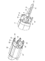
モータハウジング2の後方には、図2にも示すように、リヤカバー8内へ突出してモータの電機子26の後端を軸支する軸受部9が一体に形成されて、軸受部9の周囲に、4つの四角筒状のガイドリブ10,10・・が、モータハウジング2の軸線と平行に配設されると共に、軸受部9を中心とした点対称位置でガイドリブ10,10の間に一対のブラシホルダ11,11が設けられている。また、同じく軸受部9を中心とした点対称位置でガイドリブ10とブラシホルダ11との間を仕切る上下の仕切壁12,12には、それぞれ上下方向の係止溝13が形成されている。
As shown in FIG. 2, a
さらに、軸受部9の後面には、リヤカバー8の後部まで延びてリヤカバー8の後面からネジ固定されるネジ止めボス14が突設されて、ネジ止めボス14の左右の側面に、補強リブ15,15がネジ止めボス14を挟んだ平板状となるように連設されている。加えて、軸受部9の後面左端から左側の補強リブ15の上面に掛けて、抜け止め部としての四角板状の小リブ16が立設されている。
Further, on the rear surface of the
ガイドリブ10は、先の特許文献1に開示される筒状部材に相当するもので、モータの固定子20に設けた雌端子25と、図3に示すスイッチブロック30に設けた雄端子45とを互いに差し込み接続させるもので、モータの固定子20は、コイル22,22を巻回した鉄芯21の後端面にターミナル部材23を備え、そのターミナル部材23に、コイル22,22に接続される雌端子25をそれぞれ収容した4つの前差込部24,24・・を後方へ向けて一体に形成している。
この固定子20をモータハウジング2に前側の開口から挿入することで、モータハウジング2の内面に設けた図示しない位置決め段部に当接して位置決めされると共に、前差込部24がそれぞれ対応するガイドリブ10に前方から挿入される。そして、電機子26を同様にモータハウジング2に前側の開口から固定子20に差し込むと、図1の如く電機子26の後端が軸受部9に軸支される。
The
By inserting the
一方、リヤカバー8内でモータハウジング2の後面には、スイッチブロック30が組み付けられる。このスイッチブロック30は合成樹脂の成形品で、図3に示すように、前部中央に軸受部9が嵌合する透孔32を形成した正面視四角板状のベース部31を有し、その前方に、各ガイドリブ10に対応した4つの後差込部33,33・・と、透孔32を中心とする点対称位置で上下に設けられ、モータハウジング2に設けられた係止溝13に係止する一対の係止片34,34とを備えている。35,35はブラシとの接続端子である。また、ベース部31の下側には、透孔32の一部を形成する係止板36が設けられて、係止板36に、左右一対の係止孔37,37と、両係止孔37,37の間に位置する嵌合孔38とが形成されている。
On the other hand, a
また、ベース部31の後方で透孔32の上側には、スイッチ40及びスイッチ基板42を組み込んだ本体部39が形成されて、本体部39の左側面にスイッチ40のレバー41を突出させている。この本体部39の後端には、リヤカバー8の後部から内部へ引き込まれる電源コード44を固定する受け座43が突設されている。
さらに、後差込部33には、左下の後差込部(区別するため33Aと表記する)を除いて固定子20の雌端子25に差し込み接続される雄端子45,45・・が設けられている。後差込部33Aには、前後に貫通する貫通孔46が形成されている。この後差込部33Aが後述するコントローラ端子の位置決め部となる。
A
Further, the
そして、本体部39の下面には、コントローラ60の組み付け座47が設けられている。この組み付け座47は、図3(B)に示すように、ベース部31の後面際で透孔32の左右位置と、本体部39の右側で前後方向の中央位置との3ヶ所において下向きに突設され、後ろ向きに開放する雌端子49(図6に示す)を収容して後面及び下面に後述する端子板67の進入口となるスリット50を形成した3つの接続部48,48・・と、本体部39の左側で前後方向の中央位置に接続部48と同じ高さで突設される受け突起51と、その受け突起51の後方で本体部39の左右で下向きに突設され、係止側を外に向けた逆L字状のレール突起52,52とから形成されている。各接続部48において、スリット50の形成面となる後面及び下面は、左右端よりも低くなる凹部53,54となっている。
An
ここに組み付けられるコントローラ60は、図4に示すように、扁平四角形状のボックス61に、制御回路を形成する基板62を組み込んでなり、ボックス61の後部には、速度調整用のダイヤル63が、一部をボックス61の後方へ突出させて設けられている。また、ボックス61の前面には、スイッチブロック30への組み付け状態でベース部31の係止板36に設けた係止孔37,37に係合する左右一対のフック64,64と、そのフック64,64間に位置して嵌合孔38に挿通する嵌合突起65とが設けられている。さらに、ボックス61の上面には、スイッチブロック30への組み付け状態で組み付け座47に設けたレール突起52,52に外側から係止する左右一対のL字状の係止突起66,66が突設されている。
As shown in FIG. 4, the
一方、ボックス61の上面には、基板62からスイッチブロック30に接続される雄端子となる3つの端子板67,67・・が、スイッチブロック30の雌端子49に対応した位置で前後方向に突設されている。ここで、各端子板67の後部には、端子板67に隣接し端子板67と雌端子49との接続状態でスイッチブロック30の接続部48の後面側の凹部53に嵌合する四角形状の第1突起68が立設され、各端子板67の根元には、端子板67と雌端子49との接続状態で接続部48の下面側の凹部54に嵌合する四角形状の第2突起69が形成されている。
70は、ボックス61の前面左側から前方へ突出されるコントローラ端子で、スイッチブロック30への組み付け状態で、後差込部33Aの貫通孔46を貫通するようになっている。
On the other hand, on the upper surface of the
以上の如く構成されたグラインダ1においては、モータハウジング2に対してスイッチブロック30及びコントローラ60を組み付ける場合、まずコントローラ60をスイッチブロック30に組み付ける。すなわち、図5に示すように、スイッチブロック30の組み付け座47に対してコントローラ60を後方から、各接続部48の後方に対応する端子板67が位置するようにして各接続部48及び受け突起51の上面にボックス61をセットし、そのままコントローラ60を前方へスライドさせる。すると、図6に示すように、各端子板67が前方に位置する接続部48の後面のスリット50から接続部48内に進入し、雌端子49に差し込み接続される。この状態で、端子板67側の第1突起68が接続部48の凹部53に、第2突起69が凹部54にそれぞれ嵌合して凹部53,54を閉塞する。
In the grinder 1 configured as described above, when the
また、この接続と同時に、ボックス61の係止突起66,66が組み付け座47のレール突起52,52に係止する一方、フック64,64が係止板36の係止孔37,37に係合して嵌合突起65が嵌合孔38に挿通する。さらに、コントローラ端子70が後差込部33Aの貫通孔46を貫通する。これによりコントローラ60は、スイッチブロック30へ電気的接続された状態で組み付けられる。
Simultaneously with this connection, the locking
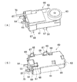
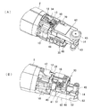
こうしてコントローラ60を組み付けたスイッチブロック30を、モータを収容したモータハウジング2に組み付ける場合、図7に示すように、モータハウジング2のガイドリブ10にスイッチブロック30の後差込部33の位置を合わせてスイッチブロック30を前方へスライドさせる。すると、図8に示すように、モータハウジング2のネジ止めボス14が、スイッチブロック30の透孔32を貫通して本体部39とコントローラ60との間を通り、後差込部33がそれぞれガイドリブ10に挿通して各雄端子45及びコントローラ端子70が固定子側の雌端子25に差し込み接続される。
When the
このとき、補強リブ15に設けた小リブ16が、スイッチ40の前面に位置してスイッチ40のスイッチブロック30からの抜け方向への移動を規制する。
その後、図9に示すように、スイッチ40のレバー41とスライドボタン7との間を連結するスライドレバー17を設け、電源コード44をスイッチブロック30に接続してリヤカバー8を組み付け、ネジ止めボス14に図示しないネジを締め付ければ、図1のようにグラインダ1の組付けが完了する。この状態でコントローラ60のダイヤル63はリヤカバー8の後部に設けた窓18を通して一部を露出させることになる。
At this time, the
Thereafter, as shown in FIG. 9, a
このように、上記形態のグラインダ1によれば、コントローラ60の組み付け面となる上面に端子板67を突設し、スイッチブロック30の組み付け面となる本体部39の下面に、雌端子49を収容して端子板67が進入するスリット50を備えた接続部48を突設して、スイッチブロック30とコントローラ60との組み付けと共にスリット50から接続部48内に進入した端子板67が雌端子49に差し込み接続されるものとして、コントローラ60の上面に、端子板67の差し込み接続状態で接続部48におけるスリット50の形成面を覆う第1、第2突起68,69を形成したことで、狭いスペースで組み付けられるスイッチブロック30とコントローラ60との端子間にも好適な防塵性を付与することができる。よって、接続作業が容易な差し込み接続を採用でき、組み付け作業が短時間且つ低コストで行える。
Thus, according to the grinder 1 of the said form, the
特にここでは、コントローラ60に、スイッチブロック30を越えてモータ側に電気的接続されるコントローラ端子70を設けて、スイッチブロック30に、コントローラ60の組み付けと共にコントローラ端子70をモータ側との接続位置に位置決めする後差込部33Aを設けたことで、間にスイッチブロック30があってもコントローラ端子70をモータ側へ精度良く確実に電気的接続することができる。
In particular, here, the
また、モータハウジング2に、スイッチブロック30の組み付けと共にスイッチ40の外面に当接してスイッチブロック30からのスイッチ40の脱落を防止する小リブ16を形成しているので、スイッチブロック30の組み付け状態でスイッチ40が自動的に抜け止めされる合理的な構造となる。
さらに、閉塞部を、端子板67に隣設され、スリット50の形成面に凹設された凹部53,54に嵌合する第1、第2突起68,69としたことで、設計変更の少ない最小限の構成で端子間の防塵が可能となる。
In addition, the
Furthermore, since the closing portion is the first and
なお、上記形態では、閉塞部として2つの突起を設けてそれぞれ接続部の後面及び下面に設けた凹部に嵌合させているが、コントローラの上面と接続部の下面との間の密着性が高ければ上下方向で嵌合する突起と凹部とは省略して差し支えない。
また、スイッチブロックとコントローラとの組み付け構造も上記形態に限らず、例えばスイッチブロックの本体部とコントローラとの上下位置を逆にしたり、レール突起と係止突起とを逆に設けたり等、適宜設計変更可能である。
In the above embodiment, the two protrusions are provided as the closing portions and are fitted in the recesses provided on the rear surface and the lower surface of the connection portion, respectively, but the adhesion between the upper surface of the controller and the lower surface of the connection portion is improved. For example, the protrusion and the recess that fit in the vertical direction may be omitted.
In addition, the assembly structure of the switch block and the controller is not limited to the above-mentioned form. For example, the switch block main body and the controller can be vertically designed so that the vertical position of the switch block and the rail protrusion and the locking protrusion are reversed. It can be changed.
さらに、接続部の後面側での突起と凹部との嵌合に代えて、図10に示すように、コントローラ60のボックス61の上面に、端子板67の後端に隣接してスイッチブロック30への接続状態で接続部48の後面に当接する後板72と、その後板72の両端から前方へ連設されてスイッチブロック30への接続状態で接続部48の側面に当接する一対の側板73,73とからなる平面視コ字状の閉塞部71を設けるようにしてもよい。この変更例によれば、接続部48の後面及び左右の側面が広く覆われるため、高い防塵性が得られる。なお、ここでは端子板67の上側の第2突起69と凹部54との嵌合をそのまま残しているが、この嵌合も省略して閉塞部71のみとしても差し支えない。
Further, instead of fitting the protrusions and the recesses on the rear surface side of the connecting portion, as shown in FIG. 10, on the upper surface of the
また、スイッチブロックに対するコントローラの組み付け方向も、上記形態のように前後方向へのスライドに限らず、上下や左右方向であってもよく、その場合は組み付け方向に合わせて閉塞部の形態を変更すればよい。例えば図11〜13は、スイッチブロック30に対して上下方向でコントローラ60を組み付ける場合の変更例を示すもので、ここではスイッチブロック30の組み付け座47に設ける接続部48を、下面にのみスリット50を設けて雌端子49を下向きに収容した四角形状の突起とする一方、コントローラ60の上面に突設した端子板67の周囲に、スイッチブロック30への組み付け状態で接続部48に外嵌して前後左右の4面を覆う四角筒状の閉塞部74を設けている。
Further, the assembly direction of the controller with respect to the switch block is not limited to sliding in the front-rear direction as in the above embodiment, but may be in the up-down direction or the left-right direction. In this case, the form of the closing portion can be changed according to the assembly direction. That's fine. For example, FIGS. 11 to 13 show a modification when the
この変更例においては、図12に示すように、スイッチブロック30の各接続部48にコントローラ60の各閉塞部74をそれぞれ正対させた状態で、スイッチブロック30にコントローラ60を上下方向で組み付けると、図13に示すように、接続部48の周囲が閉塞部74で覆われて高い防塵性が得られる。
In this modified example, as shown in FIG. 12, when the
その他、上記形態や変更例では、スイッチブロックに雌端子を、コントローラに雄端子をそれぞれ設けているが、接続部や閉塞部を含めて互いに逆側に設けるようにしてもよい。
また、スイッチブロックとコントローラとの間にネジ止めボスを貫通させているが、これをなくして接続部や受け突起、レール突起の位置や大きさを変えたりすることもできる。
In addition, in the said form and the modification, although the female terminal was provided in the switch block and the male terminal was respectively provided, you may make it provide mutually on the other side including a connection part and a closure part.
Moreover, although the screwing boss is penetrated between the switch block and the controller, the position and size of the connecting portion, the receiving projection, and the rail projection can be changed by removing this.
1・・グラインダ、2・・モータハウジング、4・・スピンドル、5・・砥石、8・・リヤカバー、9・・軸受部、10・・ガイドリブ、11・・ブラシホルダ、14・・ネジ止めボス、16・・小リブ、20・・固定子、23・・ターミナル部材、24・・前差込部、25,49・・雌端子、26・・電機子、30・・スイッチブロック、31・・ベース部、33・・後差込部、39・・本体部、40・・スイッチ、41・・レバー、45・・雄端子、47・・組み付け座、48・・接続部、50・・スリット、53,54・・凹部、60・・コントローラ、61・・ボックス、62・・基板、64・・フック、67・・端子板、68・・第1突起、69・・第2突起、70・・コントローラ端子、71,74・・閉塞部。
1 .... Grinder, 2 .... Motor housing, 4 .... Spindle, 5 .... Wheel, 8 .... Rear cover, 9 .... Bearing part, 10 .... Guide rib, 11 .... Brush holder, 14 .... Screw boss, 16 ··· Small ribs, 20 ··· Stator, 23 · · Terminal member, 24 · · Front insertion portion, 25, 49 · · Female terminal, 26 · · Armature, 30 · · Switch block, 31 · · Base , 33 ..Rear insertion part, 39 ..Main body part, 40 ..Switch, 41 ..Lever, 45 ..Male terminal, 47 ..Assembly seat, 48 ..Connection part, 50 ..Slit, 53 , 54 .. Recess, 60 .. Controller, 61 .. Box, 62 .. Board, 64 .. Hook, 67 .. Terminal board, 68 .. First projection, 69 .. Second projection, 70.
Claims (4)
前記スイッチブロックとコントローラとの何れか一方の組み付け面に雄端子を突設し、他方の組み付け面に、雌端子を収容して前記雄端子の進入口を備えた接続部を突設して、前記スイッチブロックとコントローラとの組み付けと共に前記進入口から前記接続部内に進入した前記雄端子が前記雌端子に差し込み接続されるものとして、
前記一方の組み付け面に、前記雄端子の差し込み接続状態で前記接続部における少なくとも前記進入口の形成面を覆う閉塞部を形成したことを特徴とするグラインダ。 A grinder formed by assembling a switch block having a switch for turning on / off the driving of the motor to a rear portion of a cylindrical housing containing the motor, and a controller having a control circuit for the motor in the switch block. Because
A male terminal protrudes from the assembly surface of either one of the switch block and the controller, and a connection portion is provided on the other assembly surface that accommodates the female terminal and includes an entrance of the male terminal. Assuming that the male terminal that has entered the connecting portion from the entrance along with the assembly of the switch block and the controller is inserted and connected to the female terminal,
The grinder characterized by forming the obstruction | occlusion part which covers the formation surface of the said entrance at least in the said connection part in the insertion state of the said male terminal in the said one assembly surface.
Priority Applications (6)
| Application Number | Priority Date | Filing Date | Title |
|---|---|---|---|
| JP2010107501A JP5468459B2 (en) | 2010-05-07 | 2010-05-07 | Grinder |
| US13/088,848 US8657033B2 (en) | 2010-05-07 | 2011-04-18 | Grinder |
| EP11162928.3A EP2384855B1 (en) | 2010-05-07 | 2011-04-19 | Grinder with improved connection between controller and switch block for better protection against grinding dust |
| BRPI1101855-0A BRPI1101855B1 (en) | 2010-05-07 | 2011-04-26 | ESMERIL |
| CN2011101173288A CN102233543A (en) | 2010-05-07 | 2011-05-05 | Grinder |
| RU2011118417/02A RU2564496C2 (en) | 2010-05-07 | 2011-05-06 | Grinding machine |
Applications Claiming Priority (1)
| Application Number | Priority Date | Filing Date | Title |
|---|---|---|---|
| JP2010107501A JP5468459B2 (en) | 2010-05-07 | 2010-05-07 | Grinder |
Publications (2)
| Publication Number | Publication Date |
|---|---|
| JP2011235376A JP2011235376A (en) | 2011-11-24 |
| JP5468459B2 true JP5468459B2 (en) | 2014-04-09 |
Family
ID=44279166
Family Applications (1)
| Application Number | Title | Priority Date | Filing Date |
|---|---|---|---|
| JP2010107501A Active JP5468459B2 (en) | 2010-05-07 | 2010-05-07 | Grinder |
Country Status (6)
| Country | Link |
|---|---|
| US (1) | US8657033B2 (en) |
| EP (1) | EP2384855B1 (en) |
| JP (1) | JP5468459B2 (en) |
| CN (1) | CN102233543A (en) |
| BR (1) | BRPI1101855B1 (en) |
| RU (1) | RU2564496C2 (en) |
Cited By (1)
| Publication number | Priority date | Publication date | Assignee | Title |
|---|---|---|---|---|
| DE102022125183A1 (en) | 2021-10-05 | 2023-04-06 | Makita Corporation | POWER TOOL |
Families Citing this family (10)
| Publication number | Priority date | Publication date | Assignee | Title |
|---|---|---|---|---|
| JP6045380B2 (en) * | 2013-02-08 | 2016-12-14 | リョービ株式会社 | Vertical power tool |
| US9954418B2 (en) * | 2014-03-17 | 2018-04-24 | Makita Corporation | Power tool |
| JP6717124B2 (en) * | 2015-12-29 | 2020-07-01 | 工機ホールディングス株式会社 | Electric tool |
| DE102016222532A1 (en) * | 2016-11-16 | 2018-05-17 | Robert Bosch Gmbh | Electric machine with a brush holder component and a plug module |
| JP6874481B2 (en) * | 2017-03-31 | 2021-05-19 | 工機ホールディングス株式会社 | Electric tool |
| US11007632B2 (en) * | 2017-12-01 | 2021-05-18 | Makita Corporation | Power tool |
| JP7210261B2 (en) | 2018-12-14 | 2023-01-23 | 株式会社マキタ | ELECTRIC WORKING MACHINE AND METHOD FOR MANUFACTURING STATOR IN MOTOR FOR ELECTRIC WORKING MACHINE |
| DE102019134135A1 (en) | 2019-12-12 | 2021-06-17 | Metabowerke Gmbh | Device for connecting a power cord |
| JP2021126708A (en) * | 2020-02-10 | 2021-09-02 | 株式会社マキタ | Controller for power tool and power tool |
| US11837935B2 (en) | 2021-02-02 | 2023-12-05 | Black & Decker, Inc. | Canned brushless motor |
Family Cites Families (15)
| Publication number | Priority date | Publication date | Assignee | Title |
|---|---|---|---|---|
| JPS5761480A (en) * | 1980-09-26 | 1982-04-13 | Hitachi Koki Kk | Motor tool |
| US4673837A (en) * | 1984-05-11 | 1987-06-16 | Amp Incorporated | Motor brush assembly |
| DE59008112D1 (en) | 1989-07-15 | 1995-02-09 | Kress Elektrik Gmbh & Co | Power tool. |
| RU2032520C1 (en) * | 1990-10-01 | 1995-04-10 | Казанский Авиационный Институт Им.А.Н.Туполева | Polishing manually-operated machine |
| JP3148450B2 (en) * | 1993-01-28 | 2001-03-19 | 株式会社マキタ | Portable power tool with internal wiring blocked and assembly method |
| JPH08290371A (en) * | 1995-02-23 | 1996-11-05 | Makita Corp | Connecting structure of battery pack in electric tool |
| RU2152862C2 (en) * | 1998-08-10 | 2000-07-20 | Закрытое Акционерное Общество "Энерпред" | Hand-grinding machine |
| JP3672774B2 (en) * | 1999-10-12 | 2005-07-20 | 株式会社マキタ | Mounting structure for electrical components in portable power tools |
| DE20000223U1 (en) * | 2000-01-10 | 2001-05-23 | Bosch Gmbh Robert | Angle grinder with electric drive |
| DE10347943B4 (en) * | 2003-10-15 | 2018-08-23 | Robert Bosch Gmbh | Power tool |
| US7597157B2 (en) * | 2004-09-24 | 2009-10-06 | Robert Bosch Gmbh | Electric power tool having cooling conduits |
| US7551411B2 (en) | 2005-10-12 | 2009-06-23 | Black & Decker Inc. | Control and protection methodologies for a motor control module |
| DE102006022996A1 (en) * | 2006-05-17 | 2007-11-22 | Robert Bosch Gmbh | Electrical power supply device for an electric hand tool |
| JP5001824B2 (en) * | 2007-12-27 | 2012-08-15 | 株式会社マキタ | Electric tool |
| JP5323364B2 (en) | 2008-02-15 | 2013-10-23 | 株式会社マキタ | Electric tool |
-
2010
- 2010-05-07 JP JP2010107501A patent/JP5468459B2/en active Active
-
2011
- 2011-04-18 US US13/088,848 patent/US8657033B2/en active Active
- 2011-04-19 EP EP11162928.3A patent/EP2384855B1/en active Active
- 2011-04-26 BR BRPI1101855-0A patent/BRPI1101855B1/en active IP Right Grant
- 2011-05-05 CN CN2011101173288A patent/CN102233543A/en active Pending
- 2011-05-06 RU RU2011118417/02A patent/RU2564496C2/en active
Cited By (1)
| Publication number | Priority date | Publication date | Assignee | Title |
|---|---|---|---|---|
| DE102022125183A1 (en) | 2021-10-05 | 2023-04-06 | Makita Corporation | POWER TOOL |
Also Published As
| Publication number | Publication date |
|---|---|
| EP2384855B1 (en) | 2017-06-14 |
| RU2564496C2 (en) | 2015-10-10 |
| EP2384855A3 (en) | 2013-11-13 |
| CN102233543A (en) | 2011-11-09 |
| US8657033B2 (en) | 2014-02-25 |
| EP2384855A2 (en) | 2011-11-09 |
| BRPI1101855B1 (en) | 2020-09-15 |
| RU2011118417A (en) | 2012-11-20 |
| JP2011235376A (en) | 2011-11-24 |
| US20110272264A1 (en) | 2011-11-10 |
| BRPI1101855A2 (en) | 2012-11-20 |
Similar Documents
| Publication | Publication Date | Title |
|---|---|---|
| JP5468459B2 (en) | Grinder | |
| JP2002160581A (en) | Vehicular lighting tool and driving apparatus for rotation | |
| JP2012151961A (en) | Electric connection box for vehicle | |
| JP3788905B2 (en) | Vehicle lamp and drive device for rotation | |
| JP4188792B2 (en) | motor | |
| WO2021161623A1 (en) | Controller for electric power tool and electric power tool | |
| JP3910359B2 (en) | Vehicle lamp | |
| JP5399722B2 (en) | Control circuit member and motor | |
| JP5936896B2 (en) | Motor equipment | |
| JP5965176B2 (en) | Motor device and assembly method thereof | |
| JP4755857B2 (en) | Motor with reduction mechanism | |
| JP5877105B2 (en) | Motor equipment | |
| JP5877106B2 (en) | Motor equipment | |
| JP2007259516A (en) | Motor | |
| JP2018165516A (en) | Gear with magnet, and motor and wiper motor using gear with magnet | |
| JP5216200B2 (en) | Brush holder for electric motor, electric motor and brush holder molding apparatus | |
| JP2007336800A (en) | Brush holder | |
| JP5280926B2 (en) | Wiring storage structure for electric tools | |
| JP2018014166A (en) | connector | |
| JP5965177B2 (en) | Motor equipment | |
| JP2023055115A (en) | Electric power tool | |
| JP2014064381A (en) | Electronic unit mounting structure | |
| JP2018148730A (en) | Brush, brush device, motor and wiper motor | |
| JPH0649097Y2 (en) | Motor circuit breaker storage structure | |
| US4388002A (en) | Connector for arrangement for a-c. clock mechanism |
Legal Events
| Date | Code | Title | Description |
|---|---|---|---|
| A621 | Written request for application examination |
Free format text: JAPANESE INTERMEDIATE CODE: A621 Effective date: 20121129 |
|
| A977 | Report on retrieval |
Free format text: JAPANESE INTERMEDIATE CODE: A971007 Effective date: 20131224 |
|
| TRDD | Decision of grant or rejection written | ||
| A01 | Written decision to grant a patent or to grant a registration (utility model) |
Free format text: JAPANESE INTERMEDIATE CODE: A01 Effective date: 20140107 |
|
| A61 | First payment of annual fees (during grant procedure) |
Free format text: JAPANESE INTERMEDIATE CODE: A61 Effective date: 20140129 |
|
| R150 | Certificate of patent or registration of utility model |
Ref document number: 5468459 Country of ref document: JP Free format text: JAPANESE INTERMEDIATE CODE: R150 Free format text: JAPANESE INTERMEDIATE CODE: R150 |
|
| R250 | Receipt of annual fees |
Free format text: JAPANESE INTERMEDIATE CODE: R250 |
|
| R250 | Receipt of annual fees |
Free format text: JAPANESE INTERMEDIATE CODE: R250 |
|
| R250 | Receipt of annual fees |
Free format text: JAPANESE INTERMEDIATE CODE: R250 |
|
| R250 | Receipt of annual fees |
Free format text: JAPANESE INTERMEDIATE CODE: R250 |
|
| R250 | Receipt of annual fees |
Free format text: JAPANESE INTERMEDIATE CODE: R250 |
|
| R250 | Receipt of annual fees |
Free format text: JAPANESE INTERMEDIATE CODE: R250 |
|
| R250 | Receipt of annual fees |
Free format text: JAPANESE INTERMEDIATE CODE: R250 |
|
| R250 | Receipt of annual fees |
Free format text: JAPANESE INTERMEDIATE CODE: R250 |