JP5468228B2 - Straddle-type electric vehicle - Google Patents
Straddle-type electric vehicle Download PDFInfo
- Publication number
- JP5468228B2 JP5468228B2 JP2008254760A JP2008254760A JP5468228B2 JP 5468228 B2 JP5468228 B2 JP 5468228B2 JP 2008254760 A JP2008254760 A JP 2008254760A JP 2008254760 A JP2008254760 A JP 2008254760A JP 5468228 B2 JP5468228 B2 JP 5468228B2
- Authority
- JP
- Japan
- Prior art keywords
- frame
- battery
- main
- space
- main battery
- Prior art date
- Legal status (The legal status is an assumption and is not a legal conclusion. Google has not performed a legal analysis and makes no representation as to the accuracy of the status listed.)
- Expired - Fee Related
Links
Images


Classifications
-
- Y02T10/7005—
Description
本発明は、前輪を下端部で軸支するフロントフォークおよび操向ハンドルを操向可能に支承するヘッドパイプと、該ヘッドパイプから後下がりに延びるメインフレームと、後輪を回転駆動する動力を発揮する電動モータとを備える鞍乗型電動車両に関する。 The present invention exhibits a front fork that pivotally supports the front wheel at the lower end and a head pipe that supports the steering handle so that the steering wheel can be steered, a main frame that extends rearwardly downward from the head pipe, and power for rotationally driving the rear wheel. The present invention relates to a straddle-type electric vehicle including an electric motor.
ヘッドパイプから後下がりに延びるメインフレームの下方に、電動モータに電力を供給するバッテリを配置するようにした自動二輪車が、特許文献1で知られている。
ところが、上記特許文献1で開示されたものでは、メインフレームから垂下されたフロントブラケットの下部と、メインフレームの後端から下方に延びるピボットフレームの下部との間に、後輪を回転駆動する動力を発揮する電動モータを有するモータユニットが取付けられており、バッテリは、モータユニットおよびメインフレーム間の狭い空間に配置されているので、大型のバッテリを配置することが困難である。 However, in the one disclosed in Patent Document 1, the power for rotationally driving the rear wheel between the lower portion of the front bracket suspended from the main frame and the lower portion of the pivot frame extending downward from the rear end of the main frame. A motor unit having an electric motor that exhibits the above is attached, and the battery is disposed in a narrow space between the motor unit and the main frame, so that it is difficult to dispose a large battery.
本発明は、かかる事情に鑑みてなされたものであり、より大型のバッテリを配置可能とするとともにバッテリで発生する熱を乗員に影響が及ばないように排出し得るようにした鞍乗型電動車両を提供することを目的とする。 The present invention has been made in view of the above circumstances, and is a straddle-type electric vehicle capable of disposing a larger battery and discharging heat generated by the battery so as not to affect the occupant. The purpose is to provide.
上記目的を達成するために、請求項1記載の発明は、前輪を下端部で軸支するフロントフォークおよび操向ハンドルを操向可能に支承するヘッドパイプならびに該ヘッドパイプから後下がりに延びるメインフレームを備える車体フレームと、後輪を回転駆動する動力を発揮する電動モータとを備える鞍乗型電動車両であって、前記車体フレームは、前記ヘッドパイプもしくは前記メインフレームの前端部に連設されて下方に延びるダウンフレームと、前記メインフレームの後端部に連設されて下方に延びるピボットフレームと、乗員用シートを支持するようにして前記メインフレームの後部に連なるシートレールとを有し、前記電動モータに電力を供給するメインバッテリが、前記ダウンフレーム、前記ピボットフレームおよび前記メインフレームで囲まれる第1の空間に配置され、前記電動モータが第1の空間と異なる位置に配置されるものにおいて、車両前方からの走行風を前部から導入すると共に後側上部から排出することを可能として形成されるバッテリボックスが前記第1の空間に配置されていて、そのバッテリボックスの上面が、前記後下がりに延びるメインフレームの下面に沿うよう、後方に向かうにつれて段階的に低く形成され、前記バッテリボックスは前部が後部よりも車幅方向で幅広に形成されると共に、該バッテリボックスの下面が車両側面視で水平に延びて地面と対面しており、前記バッテリボックスの内部には、前記メインバッテリが該バッテリボックスの形状に合わせて収容され、前記メインバッテリで温められた空気を第1の空間の後側に吸引して乗員用シートの後方に排出する第1の冷却用ファンが、前記車体フレームに支持され、前記シートレール及び前記メインフレームで囲まれて前記乗員用シートの下方に形成される第2の空間に、前記メインバッテリに代わって前記電動モータに電力を供給し得るサブバッテリが配置されると共に、そのサブバッテリで温められた空気を前記第2の空間から吸引して乗員用シートの後方に排出する第2の冷却用ファンが、前記第1の冷却用ファンよりも車体後方側に配置されて前記車体フレームに支持されることを特徴とする。 In order to achieve the above object, the invention described in claim 1 includes a front fork for pivotally supporting a front wheel at a lower end portion, a head pipe for pivotally supporting a steering handle, and a main frame extending rearwardly downward from the head pipe. A straddle-type electric vehicle including a vehicle body frame and an electric motor that exerts power for rotationally driving a rear wheel, wherein the vehicle body frame is connected to a front end portion of the head pipe or the main frame. A down frame that extends downward, a pivot frame that extends continuously from the rear end of the main frame, and a seat rail that continues to the rear of the main frame so as to support an occupant seat; A main battery for supplying electric power to the electric motor includes the down frame, the pivot frame, and the main frame. When the electric motor is disposed in a first space surrounded by a vehicle, and the electric motor is disposed at a position different from the first space, the traveling wind from the front of the vehicle is introduced from the front and discharged from the upper rear side. The battery box is formed in the first space, and the upper surface of the battery box is gradually lowered toward the rear so as to be along the lower surface of the main frame extending downward. The battery box has a front portion that is wider than the rear portion in the vehicle width direction, and a lower surface of the battery box that extends horizontally in a vehicle side view and faces the ground. The main battery is accommodated in accordance with the shape of the battery box, and the air heated by the main battery is sucked to the rear side of the first space. A first cooling fan that is discharged to the rear of the passenger seat is supported by the vehicle body frame, surrounded by the seat rail and the main frame, and formed in a second space formed below the passenger seat. A sub-battery that can supply electric power to the electric motor is disposed in place of the main battery, and air heated by the sub-battery is sucked from the second space and discharged to the rear of the passenger seat. The second cooling fan is disposed on the rear side of the vehicle body with respect to the first cooling fan and is supported by the vehicle body frame.
なお実施例のメインバッテリボックス32が本発明のバッテリボックスに対応し、第2実施例ではリヤフレーム52が本発明のシートレールに対応する。
The
本発明によれば、メインフレーム、ダウンフレームおよびピボットフレームで囲まれる第1の空間を、その第1の空間と異なる位置に電動モータが配置されることによって大きな空間とし、その大きな空間にメインバッテリを配置することで、より大型のメインバッテリを配置することができる。しかもメインバッテリで温められた空気を第1の空間の後側に吸引する第1の冷却用ファンが乗員用シートの後方に空気を排出するので、メインバッテリで発生する熱を、乗員用シートの後方に排出することができる。 According to the present invention, the first space surrounded by the main frame, the down frame, and the pivot frame is made large by disposing the electric motor at a position different from the first space, and the main battery is placed in the large space. By disposing, a larger main battery can be disposed. In addition, since the first cooling fan that sucks the air heated by the main battery to the rear side of the first space discharges air to the rear of the occupant seat, the heat generated by the main battery is transferred to the occupant seat. It can be discharged backwards.
またメインバッテリを収容するバッテリボックスが、車両前方からの走行風を前部から導入するとともに後側上部から排出することを可能として形成されるので、第1の冷却用ファンの作動によってバッテリボックス内の空気を効果的に排出することができ、バッテリボックス内のメインバッテリを効果的に冷却することができる。 Further, since the battery box that accommodates the main battery is formed so that the traveling wind from the front of the vehicle can be introduced from the front and discharged from the rear upper part, the operation of the first cooling fan causes the inside of the battery box to The air can be effectively discharged, and the main battery in the battery box can be effectively cooled.
更にシートレール及びメインフレームで囲まれて乗員用シートの下方に形成される第2の空間に、メインバッテリに代わって電動モータに電力を供給し得るサブバッテリが配置されるので、メインバッテリが空になったときには、そのメインバッテリに代わってサブバッテリから電動モータに電力を供給することができる。しかもそのサブバッテリで温められた空気を前記第2の空間から吸引して乗員用シートの後方に排出する第2の冷却用ファンが、第1の冷却用ファンよりも車体後方側に配置されて車体フレームに支持されるので、サブバッテリで発生する熱を、乗員用シートの後方に排出することができる。 In addition, a sub-battery that can supply power to the electric motor instead of the main battery is disposed in the second space that is surrounded by the seat rail and the main frame and is formed below the passenger seat. In this case, electric power can be supplied from the sub battery to the electric motor instead of the main battery. In addition, a second cooling fan that sucks the air heated by the sub-battery from the second space and discharges it to the rear of the passenger seat is disposed on the rear side of the vehicle body relative to the first cooling fan. Since it is supported by the body frame, the heat generated by the sub-battery can be discharged to the rear of the passenger seat.
以下、本発明の実施の形態を、添付の図面に示した本発明の実施例に基づいて説明する。 DESCRIPTION OF THE PREFERRED EMBODIMENTS Embodiments of the present invention will be described below based on examples of the present invention shown in the accompanying drawings.
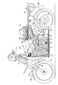
図1〜図5は本発明の第1実施例を示すものであり、図1は自動二輪車の左側面図、図2は図1の2矢視図、図3は車体カバーを外した状態での自動二輪車の左側面図、図4は図3の4矢視図、図5はバッテリの着脱操作を説明するための図である。
1 to 5 show a first embodiment of the present invention. FIG. 1 is a left side view of a motorcycle, FIG. 2 is a view taken in the direction of the
先ず図1〜図4において、鞍乗型電動車両である自動二輪車の車体フレームFAは、下端部で前輪WFを軸支するフロントフォーク11ならびに該フロントフォーク11の上部に連結されるバー状の操向ハンドル12を操向可能に支承するヘッドパイプ13と、該ヘッドパイプ13から後下がりに延びるパイプ状のメインフレーム14と、前記メインフレーム14の後端部に連設されて下方に延びるピボットフレーム16と、前記メインフレーム14の後端部に連設されて後方に延びる左右一対のリヤフレーム17…と、メインフレーム14の後部および両リヤフレーム17…の中間部間に設けられて後上がりに傾斜した左右一対のシートレール18…とを備える。
1 to 4, a body frame FA of a motorcycle, which is a saddle-type electric vehicle, includes a
両リヤフレーム17…は、前記メインフレーム14の後端部から後上がりに延びる傾斜部17a…と、該傾斜部17a…の後端から後方に向かって水平に延びる水平部17b…とを一体に有し、両水平部17b…の後部が相互に連結される。また前記シートレール18…の後端は、リヤフレーム17…における傾斜部17a…の後側上部に連設される。
The
前記フロントフォーク11には、前輪WFを上方から覆うフロントフェンダ20が取付けられ、前記リヤフレーム17…には、後輪WRを上方から覆うリヤフェンダ21が取付けられる。またピボットフレーム16の下部には、メインスタンド22が回動可能に取付けられる。しかも前記ピボットフレーム16には、後端部に後輪WRを軸支するスイングアーム23の前端部が上下に揺動可能に連結され、前記リヤフレーム17…における水平部17b…の前部および前記スイングアーム23の後部間にはリヤクッションユニット24…が設けられる。また前記リヤフレーム17…における水平部17b…上には荷台25が設けられる。
A
前記荷台25の前方には乗員用シート28が配置されており、この乗員用シート28は前記シートレール18…にシート支持枠19を介して支持されており、図5で示すように、該乗員用シート28を前方に回動すること可能として前記シート支持枠19で支持される。而してシート支持枠19は、乗員用シート28を支持する水平なシート支持部19aと、該シート支持部19aの前部から下方に延びる前脚部19bと、前記シート支持部19aの後部から下方に延びる後脚部19cとを有し、前脚部19bの下端が前記シートレール18…の前部に固着され、前記後脚部19cの下端が前記リヤフレーム17…における傾斜部17a…の後部に固着される。
An
ところで、前記後輪WRは電動モータ29が発揮する動力で回転駆動されるものであり、その電動モータ29に電力を供給するメインバッテリ30が、前記メインフレーム14と、車体フレームFAの一部を構成するとともに前記ヘッドパイプ13もしくは前記メインフレーム14の前端部(この実施例ではメインフレーム14の前端部)に連設されて下方に延びるダウンフレーム15と、前記ピボットフレーム16とで囲まれる第1の空間S1(図1および図3参照)に配置される。一方、前記電動モータ29は、その第1の空間S1と異なる位置に配置されるものであり、この実施例において電動モータ29は、第1の空間S1よりも後方であって前記スイングアーム23の後端部に、回転軸線を前記後輪WRと同軸として配設される。
By the way, the rear wheel WR is rotationally driven by the power exerted by the
前記メインバッテリ30は、複数のメインバッテリ用セル31…が相互に結合されることで構成されるものであり、各メインバッテリ用セル31…は、前記車体フレームFAにおけるメインフレーム14にほぼ沿う上面を有してメインフレーム14、ダウンフレーム15およびピボットフレーム16で囲まれる第1の空間S1に配置されるメインバッテリボックス32内に、該メインバッテリボックス32の形状に合わせて整列配置される。
The
而して前記メインバッテリボックス32の上面は、後下がりに延びるメインフレーム14の下面に沿うように形成されるものであり、後方に向かうにつれて段階的に低くなるように形成される。
Thus, the upper surface of the
しかもダウンフレーム15およびピボットフレーム16の下部間に、ダウンフレーム15およびピボットフレーム16を連結してメインバッテリボックス32を支持する連結状態と、その連結を解除してメインバッテリボックス32を下方に取り出し可能とした連結解除状態とを切換えることを可能としたロアフレーム33が設けられるものであり、この実施例では、ロアフレーム33の後部が前記ピボットフレーム16の下部に支軸34を介して揺動可能に連結され、ロアフレーム33の前部は、着脱可能な連結ピン35等によって前記ダウンフレーム15の下部に着脱可能に連結される。すなわちロアフレーム33は、その前部をダウンフレーム15に連結した連結状態と、前部をダウンフレーム15から外した連結解除状態とを切換え可能であり、連結解除状態では図5で示すようにロアフレーム33をその前部が下方位置となるように回動して、メインバッテリボックス32を下方に取り出することができる。
In addition, it is possible to connect the
しかも連結状態にあるロアフレーム33で支持されたメインバッテリボックス32の上面および車体フレームFA間には弾性部材36…が介装される。
In addition,
また前記ピボットフレーム16の下部には、該ピボットフレーム16から前方に延びる左右一対のステップ用フレーム37,37が連設されており、それらのステップ用フレーム37…の前端に、乗員用シート28に座った乗員が足を載せるためのステップ38,38がそれぞれ設けられる。
A pair of left and
而してメインバッテリ30を収納するメインバッテリボックス32は、平面視では図2および図4で示すように、前記ステップ用フレーム37…および前記ステップ38…に重なることはなく、この実施例では、メインバッテリボックス32の後部両側に配置される前記ステップ用フレーム37…および前記ステップ38…に対応して、メインバッテリボックス32すなわちメインバッテリ30の後部の幅は、メインバッテリボックス32の前部の幅よりも小さく設定される。しかもメインバッテリ30の容量を大きくするために、メインバッテリボックス32は、その後端部が側面視で前記ステップ用フレーム37…と重なるようにして後方に延びて形成される。
Thus, the
また前記メインフレーム14と、前記シートレール18…とで囲まれて前記乗員用シート28の下方に位置する第2の空間S2に、前記メインバッテリ30に代わって前記電動モータ29に電力を供給し得るサブバッテリ40が、図5で示すように乗員用シート28を前方に回動した状態で第2の空間S2から離脱させることを可能として配置され、このサブバッテリ40はシート支持枠19で囲まれる。而して前記電動モータ29は第1の空間S1と異なって第1の空間S1よりも後方の位置に配置されるものであり、前記スイングアーム23の後端部に配設されるので、第2の空間S2とも異なる位置に配置されることになる。
Further, electric power is supplied to the
前記サブバッテリ40は、複数のサブバッテリ用セル41…が相互に結合されて構成されるものであり、それらのサブバッテリ用セル41…は、第2の空間S2に合わせて形成されて第2の空間S2に配置されるサブバッテリボックス42内に、該サブバッテリボックス42の形状に合わせて整列配置される。
The sub-battery 40 is configured by connecting a plurality of
前記車体フレームFAにおけるシートレール18…には、前記メインバッテリ30で温められた空気を第1の空間S1の後側に吸引して前記乗員用シート28の後方に排出する第1の冷却用ファン43が支持されており、第1の空間S1に配置されるメインバッテリボックス32は、自動二輪車の前方からの走行風を前部から導入するとともに後側上部から排出することを可能として形成される。
The
また前記車体フレームFAにおけるシート支持枠19の後脚部19cには、第2の空間S2に配置されているサブバッテリボックス42で温められた空気を第2の空間S2から吸引して乗員用シート28の後方に排出する第2の冷却用ファン44が支持される。
The
ところで、前記乗員用シート28に座った乗員の左右両脚部はレッグシールド45…でそれぞれ前方から覆われるものであり、これらのレッグシールド45…は、前記メインフレーム14を上方から覆うとともに前記メインバッテリボックス32の前部を両側から覆う合成樹脂製のセンターカバー46に一体に設けられる。一方、前記シートレール18…、シート支持枠19、サブバッテリボックス42および第2の冷却ファン44は、前記乗員用シート28の下方に配置される左右一対の合成樹脂から成るサイドカバー47…で両側から覆われるものであり、合成樹脂から成るサイドカバー47…は前記センターカバー46に連設され、該センターカバー46とともに車体カバー48を構成する。
By the way, the left and right legs of the occupant sitting on the
しかも前記メインバッテリ30および前記サブバッテリ40から供給される電力を受けて前記電動モータ29を駆動する駆動回路手段49が、両サイドカバー47…の一方内に収容され、両サイドカバー47…の他方内に、前記メインバッテリ30に充電するための充電回路手段50が収容される。また前記乗員用シート28および前記サブバッテリボックス42間には、充電用コード51が収容される。
Moreover, a drive circuit means 49 that receives the power supplied from the
次にこの第1実施例の作用について説明すると、後輪WRを回転駆動する動力を発揮する電動モータ29に電力を供給するメインバッテリ30が、メインフレーム14の前端部に連設されて下方に延びるダウンフレーム15と、メインフレーム14の後端部に連設されて下方に延びるピボットフレーム16と、メインフレーム14とで囲まれる第1の空間S1に配置され、電動モータ29が第1の空間S1と異なる位置に配置されるので、第1の空間S1を大きな空間とし、その大きな第1の空間S1にメインバッテリ30を配置することで、大型のメインバッテリ30を配置することができる。
Next, the operation of the first embodiment will be described. A
またピボットフレーム16には、後端部に後輪WRを軸支するスイングアーム23の前端部が上下に揺動可能に連結されており、電動モータ29がその回転軸線を後輪WRと同軸としてスイングアーム23の後端部に配設されるので、メインバッテリ30の配置スペースを確保しつつ電動モータ29をコンパクトに配置することができる。
The
またダウンフレーム15およびピボットフレーム16の下部間に、ダウンフレーム15およびピボットフレーム16を連結してメインバッテリボックス32を支持する連結状態と、その連結を解除してメインバッテリボックス32を下方に取り出し可能とした連結解除状態とを切換えることを可能としたロアフレーム33が設けられるので、ロアフレーム33の連結解除状態では、メインバッテリボックス32を下方に取り出すことが可能となり、メインバッテリ30のメンテナンス作業が容易となる。
Further, a connection state in which the
また前記第1の空間S1にメインバッテリ30が配置されるのに対して、メインバッテリ30に代わって前記電動モータ29に電力を供給し得るサブバッテリ40が、メインフレーム14の後端部に連設されて後上がりに延びるリヤフレーム17…と、メインフレーム14の後部およびリヤフレーム17…の中間部間を連結するとともに乗員用シート28を支持するシートレール18…と、前記メインフレーム14とで囲まれる第2の空間S2に配置され、電動モータ29は第2の空間S2とも異なる位置に配置されるので、電動モータ29が配置されないことによって大きく形成し得る第1および第2の空間S1,S2にメインバッテリ30およびサブバッテリ40を配置することで、より大型のメインバッテリ30およびサブバッテリ40を配置することができ、メインバッテリ30が空になったときにはメインバッテリ30に代わってサブバッテリ40から電動モータ29に電力を供給することができる。
Further, while the
またメインバッテリ30は、複数のメインバッテリ用セル31…が相互に結合されて構成されるものであり、それらのメインバッテリ用セル31…が、メインフレーム14の下面にほぼ沿う上面を有して前記メインフレーム14、前記ダウンフレーム15および前記ピボットフレーム16で囲まれる第1の空間S1に配置されるメインバッテリボックス32内に、該メインバッテリボックス32の形状に合わせて整列配置され、サブバッテリ40は、複数のサブバッテリ用セル41…が相互に結合されて構成され、それらのサブバッテリ用セル41…が、第2の空間S2に合わせて形成されて第2の空間S2に配置されるサブバッテリボックス42内に、該サブバッテリボックス42の形状に合わせて整列配置されるので、メインバッテリボックス32内により多くのメインバッテリ用セル31…を収納することができ、サブバッテリボックス42内により多くのサブバッテリ用セル41…を収納することができる。
Further, the
またシートレール18…上に設けられる乗員用シート28の下方に、前記シートレール18…を側方から覆うサイドカバー47…が配置され、メインバッテリ30またはサブバッテリ40から供給される電力を受けて電動モータ29を駆動する駆動回路手段49がサイドカバー49内に収容されるので、駆動回動手段49が外方に見えないようにして外観性を高めることができる。
Further, a
しかも左右一対の前記サイドカバー47…がシートレール18…の左右両側に配置され、両サイドカバー47…の一方内に前記駆動回路手段49が収容され、両サイドカバー47…の他方内に、前記メインバッテリ30に充電するための充電回路手段50が収容されるので、左右の重量バランスを良好にしつつ両サイドカバー47…内の空間を有効に利用して、良好な外観性を得ながら駆動回路手段49および充電回路手段50を配置することができる。
In addition, a pair of left and right side covers 47 are disposed on the left and right sides of the
また車体フレームFAにおけるシートレール18…には、メインバッテリ30で温められた空気を第1の空間S1の後側に吸引して乗員用シート28の後方に排出する第1の冷却用ファン43が支持されており、第1の空間S1に配置されるメインバッテリボックス32は、自動二輪車の前方からの走行風を前部から導入するとともに後側上部から排出することを可能として形成されるので、メインバッテリ30で発生する熱を、乗員用シート28の後方に排出することができる。
Further, the
しかもメインバッテリボックス32は、自動二輪車の前方からの走行風を前部から導入するとともに後側上部から排出することを可能として形成されており、そのメインバッテリボックス32にメインバッテリ30が収容されるので、第1の冷却用ファン43の作動によってメインバッテリボックス32内の空気を効果的に排出することができ、メインバッテリボックス32内のメインバッテリ30を効果的に冷却することができる。
In addition, the
またリヤフレーム17…、シートレール18…およびメインフレーム14で囲まれる第2の空間S2に、メインバッテリ30に代わって電動モータ29に電力を供給し得るサブバッテリ40が配置され、サブバッテリ40で温められた空気を第2の空間S2から吸引して乗員用シー28の後方に排出する第2の冷却用ファン44が前記車体フレームFAにおけるシート支持枠19の後脚部19cに支持されるので、サブバッテリ40で発生する熱を、乗員用シート28の後方に排出することができる。
A sub-battery 40 that can supply electric power to the
さらにメインバッテリ30およびメインバッテリボックス32は、両ステップ用フレーム37…ならびに両ステップ用フレーム37…の前端に設けられるステップ38…に平面視で重なることを避けて第1の空間S1に配置されるので、両ステップ用フレーム37…間の幅が大きくなることを避けながら乗員の足載せ性を高めることができる。また両ステップ用フレーム37…および両ステップ38…の配置によって乗員用シート28に乗員が跨がる部分ではメインバッテリ30の幅が狭くならざるを得ないのであるが、両ステップ用フレーム37…および両ステップ38…よりも前方に配置される部分でメインバッテリ30の幅を広くすることにより、乗員の足載せ性を高めつつメインバッテリボックス32の容量を極力大きくし、メインバッテリボックス32により多くのメインバッテリ用セル31…を収容してメインバッテリ30を大型化することができる。
Further, the
図6は本発明の第2実施例を示すものであり、第1実施例に対応する部分には同一の参照符号を付して図示するのみとし、詳細な説明は省略する。 FIG. 6 shows a second embodiment of the present invention. The parts corresponding to the first embodiment are indicated by the same reference numerals, and the detailed description is omitted.
この自動二輪車の車体フレームFBは、下端部で前輪WFを軸支するフロントフォーク11および操向ハンドル12を操向可能に支承するヘッドパイプ13と、該ヘッドパイプ13から後下がりに延びるパイプ状のメインフレーム14と、左右に分割可能として前記メインフレーム13の下部に連設されるリヤフレーム52とを備え、リヤフレーム52は、前記メインフレーム14の後端に連なって下方に延びるピボットフレーム53を一体に有するとともに、乗員用シート28を支持するシートレールならびに後輪WRを上方から覆うリヤフェンダの機能を有する。
A body frame FB of the motorcycle includes a
前記ピボットフレーム53の下部には、該ピボットフレーム53から前方に延びる左右一対のステップ用フレーム37…が連設されており、それらのステップ用フレーム37…の前端に、乗員用シート28に座った乗員が足を載せるためのステップ38…が設けられる。
A pair of left and right step frames 37 extending forward from the
前記ピボットフレーム53の下部に揺動可能に支承されるスイングアーム23の後部に後輪WRが軸支されるととともに、後輪WRを回転駆動する動力を発揮する電動モータ29が、その回転軸線を前記後輪WRと同軸として配設される。
The rear wheel WR is pivotally supported on the rear portion of the
電動モータ29に電力を供給するメインバッテリ30は、複数のメインバッテリ用セル31…が相互に結合されることで構成されてメインバッテリボックス32内に収容されるものであり、メインフレーム14と、前記ヘッドパイプ13もしくは前記メインフレーム14の前端部(この実施例ではメインフレーム14の前端部)に連設されて下方に延びるダウンフレーム15と、前記ピボットフレーム53とで囲まれる第1の空間S1に、平面視で前記ステップ用フレーム37…および前記ステップ38…に重なることがないようにしてメインバッテリボックス32が配置され、このメインバッテリボックス32の上面は、後下がりに延びるメインフレーム14の下面に沿うようにして、後方に向かうにつれて段階的に低くなるように形成される。
A
しかもダウンフレーム15およびピボットフレーム53の下部間には、ダウンフレーム15およびピボットフレーム53を連結してメインバッテリボックス32を支持する連結状態と、その連結を解除してメインバッテリボックス32を下方に取り出し可能とした連結解除状態とを切換えることを可能としたロアフレーム33が設けられ、このロアフレーム33は、その前部をダウンフレーム15に連結した連結状態と、前部をダウンフレーム15から外した連結解除状態とを切換え可能であり、連結解除状態ではロアフレーム33をその前部が下方位置となるように回動して、メインバッテリボックス32を下方に取り出することができる。
Moreover, between the
また前記メインフレーム14と、前記シートレールの機能を果たすリヤフレーム52とで囲まれて前記乗員用シート28の下方に位置する第2の空間S2に、前記メインバッテリ30に代わって前記電動モータ29に電力を供給し得るサブバッテリ40が配置される。このサブバッテリ40は、複数のサブバッテリ用セル41…が相互に結合されて構成されるものであり、それらのサブバッテリ用セル41…は、第2の空間S2に合わせて形成されて第2の空間S2に配置されるサブバッテリボックス42内に、該サブバッテリボックス42の形状に合わせて整列配置される。
In addition, in the second space S2 that is surrounded by the
前記車体フレームFBにおけるリヤフレーム52には、メインバッテリ30で温められた空気を第1の空間S1の後側に吸引して乗員用シート28の後方に排出する第1の冷却用ファン43が支持されており、第1の空間S1に配置されるメインバッテリボックス32は、自動二輪車の前方からの走行風を前部から導入するとともに後側上部から排出することを可能として形成される。
The
また前記車体フレームFBにおけリヤフレーム52には、第2の空間S2に配置されるサブバッテリ40で温められた空気を吸引して乗員用シート28の後方に排出する第2の冷却用ファン44が支持される。
In addition, the
ところで、前記乗員用シート28に座った乗員の左右両脚部はレッグシールド45…でそれぞれ前方から覆われるものであり、これらのレッグシールド45…は、前記メインフレーム14を上方から覆うとともに前記メインバッテリボックス32の前部を両側から覆う合成樹脂製のセンターカバー46に一体に設けられる。一方、サブバッテリボックス42および第2の冷却ファン44は、前記乗員用シート28の下方に配置される左右一対の合成樹脂から成るサイドカバー54…で両側から覆われるものであり、合成樹脂から成るサイドカバー54…は前記センターカバー46およびリヤフレーム52に連設される。
By the way, the left and right legs of the occupant sitting on the
しかも前記メインバッテリ30および前記サブバッテリ40から供給される電力を受けて前記電動モータ29を駆動する駆動回路手段49と、前記メインバッテリ30に充電するための充電回路手段50とが、前記リヤフレーム52内に収容される。
In addition, drive circuit means 49 for driving the
この第2実施例によっても第1実施例と同様の効果を奏することができる。 According to the second embodiment, the same effect as that of the first embodiment can be obtained.
以上、本発明の実施例を説明したが、本発明は上記実施例に限定されるものではなく、特許請求の範囲に記載された本発明を逸脱することなく種々の設計変更を行うことが可能である。 Although the embodiments of the present invention have been described above, the present invention is not limited to the above-described embodiments, and various design changes can be made without departing from the present invention described in the claims. It is.
11・・・フロントフォーク
12・・・操向ハンドル
13・・・ヘッドパイプ
14・・・メインフレーム
15・・・ダウンフレーム
16,53・・・ピボットフレーム
18・・・シートレール
28・・・乗員用シート
29・・・電動モータ
30・・・メインバッテリ
32・・・バッテリボックスであるメインバッテリボックス
40・・・サブバッテリ
43・・・第1の冷却用ファン
44・・・第2の冷却用ファン
52・・・シートレールとしてのリヤフレーム
FA,FB・・・車体フレーム
S1・・・第1の空間
S2・・・第2の空間
WF・・・前輪
WR・・・後輪
DESCRIPTION OF
Claims (1)
前記車体フレーム(FA,FB)が、前記ヘッドパイプ(13)もしくは前記メインフレーム(14)の前端部に連設されて下方に延びるダウンフレーム(15)と、前記メインフレーム(14)の後端部に連設されて下方に延びるピボットフレーム(16,53)と、乗員用シート(28)を支持するようにして前記メインフレーム(14)の後部に連なるシートレール(18,52)とを有し、
前記電動モータ(29)に電力を供給するメインバッテリ(30)が、前記ダウンフレーム(15)、前記ピボットフレーム(16,53)および前記メインフレーム(14)で囲まれる第1の空間(S1)に配置され、前記電動モータ(29)が第1の空間(S1)と異なる位置に配置されるものにおいて、
車両前方からの走行風を前部から導入すると共に後側上部から排出することを可能として形成されるバッテリボックス(32)が前記第1の空間(S1)に配置されていて、そのバッテリボックス(32)の上面が、前記後下がりに延びるメインフレーム(14)の下面に沿うよう、後方に向かうにつれて段階的に低く形成され、
前記バッテリボックス(32)は前部が後部よりも車幅方向で幅広に形成されると共に、該バッテリボックス(32)の下面が車両側面視で水平に延びて地面と対面しており、 前記バッテリボックス(32)の内部には、前記メインバッテリ(30)が該バッテリボックス(32)の形状に合わせて収容され、
前記メインバッテリ(30)で温められた空気を第1の空間(S1)の後側に吸引して乗員用シート(28)の後方に排出する第1の冷却用ファン(43)が、前記車体フレーム(FA,FB)に支持され、
前記シートレール(18,52)及び前記メインフレーム(14)で囲まれて前記乗員用シート(28)の下方に形成される第2の空間(S2)に、前記メインバッテリ(30)に代わって前記電動モータ(29)に電力を供給し得るサブバッテリ(40)が配置されると共に、そのサブバッテリ(40)で温められた空気を前記第2の空間(S2)から吸引して乗員用シート(28)の後方に排出する第2の冷却用ファン(44)が、前記第1の冷却用ファン(43)よりも車体後方側に配置されて前記車体フレーム(FA,FB)に支持されることを特徴とする鞍乗型電動車両。 A front fork (11) for pivotally supporting the front wheel (WF) at its lower end, a head pipe (13) for supporting the steering handle (12) so as to be steerable, and a main frame extending rearwardly downward from the head pipe (13) 14) a straddle-type electric vehicle comprising a vehicle body frame (FA, FB) provided with 14) and an electric motor (29) exhibiting power for rotationally driving the rear wheels (WR),
The vehicle body frame (FA, FB) is connected to the front end of the head pipe (13) or the main frame (14) and extends downward, and the rear end of the main frame (14) A pivot frame (16, 53) connected to the rear portion and extending downward, and a seat rail (18, 52) connected to the rear portion of the main frame (14) so as to support the passenger seat (28). And
A first battery (30) in which a main battery (30) for supplying electric power to the electric motor (29) is surrounded by the down frame (15), the pivot frame (16, 53) and the main frame (14). And the electric motor (29) is arranged at a position different from the first space (S1),
A battery box (32) is formed in the first space (S1) so as to allow the traveling wind from the front of the vehicle to be introduced from the front part and discharged from the upper part of the rear side. 32) the upper surface of the main frame (14) extending in the rearward downward direction is formed so as to be lowered stepwise toward the rear,
The battery box (32) has a front portion formed wider in the vehicle width direction than a rear portion, and a lower surface of the battery box (32) extends horizontally in a vehicle side view and faces the ground. Inside the box (32), the main battery (30) is accommodated in accordance with the shape of the battery box (32),
The first cooling fan (43) for sucking the air heated by the main battery (30) to the rear side of the first space (S1) and discharging it to the rear of the occupant seat (28) includes the vehicle body Supported by the frame (FA, FB)
Instead of the main battery (30), a second space (S2) is formed below the passenger seat (28) surrounded by the seat rails (18, 52) and the main frame (14). A sub-battery (40) capable of supplying electric power to the electric motor (29) is disposed, and air warmed by the sub-battery (40) is sucked from the second space (S2) to be a passenger seat The second cooling fan (44) discharged to the rear of (28) is disposed on the vehicle body rear side with respect to the first cooling fan (43) and supported by the vehicle body frame (FA, FB). A straddle-type electric vehicle characterized by that.
Priority Applications (5)
| Application Number | Priority Date | Filing Date | Title |
|---|---|---|---|
| JP2008254760A JP5468228B2 (en) | 2008-09-30 | 2008-09-30 | Straddle-type electric vehicle |
| TW098124562A TW201012695A (en) | 2008-09-30 | 2009-07-21 | Saddle-ride electric vehicle |
| CN2009101674513A CN101712351B (en) | 2008-09-30 | 2009-08-25 | Saddle-ride electric vehicle |
| US12/552,149 US8418795B2 (en) | 2008-09-30 | 2009-09-01 | Saddle-ride electric vehicle |
| EP09171482.4A EP2168862B1 (en) | 2008-09-30 | 2009-09-28 | Saddle-ride type electric vehicle |
Applications Claiming Priority (1)
| Application Number | Priority Date | Filing Date | Title |
|---|---|---|---|
| JP2008254760A JP5468228B2 (en) | 2008-09-30 | 2008-09-30 | Straddle-type electric vehicle |
Publications (2)
| Publication Number | Publication Date |
|---|---|
| JP2010083333A JP2010083333A (en) | 2010-04-15 |
| JP5468228B2 true JP5468228B2 (en) | 2014-04-09 |
Family
ID=42247716
Family Applications (1)
| Application Number | Title | Priority Date | Filing Date |
|---|---|---|---|
| JP2008254760A Expired - Fee Related JP5468228B2 (en) | 2008-09-30 | 2008-09-30 | Straddle-type electric vehicle |
Country Status (1)
| Country | Link |
|---|---|
| JP (1) | JP5468228B2 (en) |
Families Citing this family (7)
| Publication number | Priority date | Publication date | Assignee | Title |
|---|---|---|---|---|
| JP5715642B2 (en) | 2010-11-05 | 2015-05-13 | 川崎重工業株式会社 | Straddle-type electric vehicle |
| JP5504352B2 (en) | 2010-11-12 | 2014-05-28 | 川崎重工業株式会社 | Mounting structure of power storage device in electric vehicle |
| US9463695B2 (en) | 2011-10-28 | 2016-10-11 | Kawasaki Jukogyo Kabushiki Kaisha | Straddle electric vehicle |
| US20150210339A1 (en) * | 2011-12-22 | 2015-07-30 | Takeshi Igarashi | Straddle-type electric vehicle |
| WO2014102853A1 (en) | 2012-12-25 | 2014-07-03 | 川崎重工業株式会社 | Electric vehicle |
| KR102240113B1 (en) * | 2019-04-11 | 2021-04-14 | 주식회사 모헤닉모터스 | Battery pack mounting structure for electric two wheelers |
| JP7086912B2 (en) * | 2019-10-21 | 2022-06-20 | ヤマハ発動機株式会社 | Saddle-type electric vehicle |
Family Cites Families (5)
| Publication number | Priority date | Publication date | Assignee | Title |
|---|---|---|---|---|
| JP3602494B2 (en) * | 1992-03-30 | 2004-12-15 | 本田技研工業株式会社 | Battery structure for electric vehicles |
| JPH06219359A (en) * | 1993-01-29 | 1994-08-09 | Suzuki Motor Corp | Car body frame structure of electric scooter |
| GB2307218A (en) * | 1995-11-16 | 1997-05-21 | Advanced Safe Sustainable Energy | Electric vehicle |
| JP3949446B2 (en) * | 2001-12-20 | 2007-07-25 | 本田技研工業株式会社 | Battery arrangement structure for electric vehicles |
| JP4325857B2 (en) * | 2004-01-15 | 2009-09-02 | 本田技研工業株式会社 | Electric vehicle drive device |
-
2008
- 2008-09-30 JP JP2008254760A patent/JP5468228B2/en not_active Expired - Fee Related
Also Published As
| Publication number | Publication date |
|---|---|
| JP2010083333A (en) | 2010-04-15 |
Similar Documents
| Publication | Publication Date | Title |
|---|---|---|
| US8418795B2 (en) | Saddle-ride electric vehicle | |
| TWI392620B (en) | Saddle-ride electric vehicle | |
| JP5468228B2 (en) | Straddle-type electric vehicle | |
| JP5084685B2 (en) | Straddle-type electric vehicle | |
| JP4920418B2 (en) | Composite structure vehicle frame | |
| JP5253951B2 (en) | Straddle-type electric vehicle | |
| JP2011213345A (en) | Electric two-wheeler | |
| JP2011063065A5 (en) | ||
| JP3239499U (en) | electric bike | |
| TWI751486B (en) | Saddle-ride type electric vehicle | |
| JP5329895B2 (en) | Straddle-type electric vehicle | |
| JP5162402B2 (en) | Straddle-type electric vehicle | |
| JP5276944B2 (en) | Straddle-type electric vehicle | |
| JP2013023214A (en) | Scooter type vehicle | |
| JP2011025766A (en) | Folding type power-assisted bicycle | |
| JP5528905B2 (en) | Saddle riding type electric vehicle | |
| JP2009262768A (en) | Bicycle | |
| JP2005028991A (en) | Small-sized motor-driven vehicle of standing riding type | |
| JP5437167B2 (en) | Saddle riding type electric vehicle | |
| JP2023094117A (en) | electric tricycle | |
| JP2000070424A (en) | Riding electric golf cart |
Legal Events
| Date | Code | Title | Description |
|---|---|---|---|
| A621 | Written request for application examination |
Free format text: JAPANESE INTERMEDIATE CODE: A621 Effective date: 20110526 |
|
| A131 | Notification of reasons for refusal |
Free format text: JAPANESE INTERMEDIATE CODE: A131 Effective date: 20120829 |
|
| A977 | Report on retrieval |
Free format text: JAPANESE INTERMEDIATE CODE: A971007 Effective date: 20120831 |
|
| A521 | Request for written amendment filed |
Free format text: JAPANESE INTERMEDIATE CODE: A523 Effective date: 20121029 |
|
| A131 | Notification of reasons for refusal |
Free format text: JAPANESE INTERMEDIATE CODE: A131 Effective date: 20130501 |
|
| A521 | Request for written amendment filed |
Free format text: JAPANESE INTERMEDIATE CODE: A523 Effective date: 20130628 |
|
| TRDD | Decision of grant or rejection written | ||
| A01 | Written decision to grant a patent or to grant a registration (utility model) |
Free format text: JAPANESE INTERMEDIATE CODE: A01 Effective date: 20140108 |
|
| A61 | First payment of annual fees (during grant procedure) |
Free format text: JAPANESE INTERMEDIATE CODE: A61 Effective date: 20140129 |
|
| R150 | Certificate of patent or registration of utility model |
Ref document number: 5468228 Country of ref document: JP Free format text: JAPANESE INTERMEDIATE CODE: R150 Free format text: JAPANESE INTERMEDIATE CODE: R150 |
|
| LAPS | Cancellation because of no payment of annual fees |