JP5467266B2 - Method for measuring solution components using absorbance method and measuring apparatus using the method - Google Patents
Method for measuring solution components using absorbance method and measuring apparatus using the method Download PDFInfo
- Publication number
- JP5467266B2 JP5467266B2 JP2010045892A JP2010045892A JP5467266B2 JP 5467266 B2 JP5467266 B2 JP 5467266B2 JP 2010045892 A JP2010045892 A JP 2010045892A JP 2010045892 A JP2010045892 A JP 2010045892A JP 5467266 B2 JP5467266 B2 JP 5467266B2
- Authority
- JP
- Japan
- Prior art keywords
- solution
- absorbance
- acid
- sample solution
- value
- Prior art date
- Legal status (The legal status is an assumption and is not a legal conclusion. Google has not performed a legal analysis and makes no representation as to the accuracy of the status listed.)
- Expired - Fee Related
Links
- 238000000034 method Methods 0.000 title claims description 144
- 238000002835 absorbance Methods 0.000 title claims description 105
- 239000012488 sample solution Substances 0.000 claims description 206
- 239000002253 acid Substances 0.000 claims description 123
- 239000000243 solution Substances 0.000 claims description 118
- 238000004448 titration Methods 0.000 claims description 95
- 238000005259 measurement Methods 0.000 claims description 90
- BVKZGUZCCUSVTD-UHFFFAOYSA-N carbonic acid Chemical compound OC(O)=O BVKZGUZCCUSVTD-UHFFFAOYSA-N 0.000 claims description 51
- XLYOFNOQVPJJNP-UHFFFAOYSA-N water Substances O XLYOFNOQVPJJNP-UHFFFAOYSA-N 0.000 claims description 27
- 238000000691 measurement method Methods 0.000 claims description 26
- 239000000523 sample Substances 0.000 claims description 23
- 239000007793 ph indicator Substances 0.000 claims description 22
- 238000004364 calculation method Methods 0.000 claims description 21
- 239000011259 mixed solution Substances 0.000 claims description 20
- 238000012360 testing method Methods 0.000 claims description 18
- 238000010494 dissociation reaction Methods 0.000 claims description 15
- 230000005593 dissociations Effects 0.000 claims description 15
- 230000008033 biological extinction Effects 0.000 claims description 14
- 238000004737 colorimetric analysis Methods 0.000 claims description 14
- 239000007788 liquid Substances 0.000 claims description 10
- 238000000862 absorption spectrum Methods 0.000 claims description 7
- 150000003839 salts Chemical class 0.000 claims description 7
- 238000005206 flow analysis Methods 0.000 claims description 6
- 239000012530 fluid Substances 0.000 claims description 4
- 238000002798 spectrophotometry method Methods 0.000 claims description 4
- 239000003283 colorimetric indicator Substances 0.000 claims description 2
- 238000012545 processing Methods 0.000 description 64
- CURLTUGMZLYLDI-UHFFFAOYSA-N Carbon dioxide Chemical compound O=C=O CURLTUGMZLYLDI-UHFFFAOYSA-N 0.000 description 40
- GPRLSGONYQIRFK-UHFFFAOYSA-N hydron Chemical compound [H+] GPRLSGONYQIRFK-UHFFFAOYSA-N 0.000 description 34
- 239000013535 sea water Substances 0.000 description 33
- VEXZGXHMUGYJMC-UHFFFAOYSA-N Hydrochloric acid Chemical compound Cl VEXZGXHMUGYJMC-UHFFFAOYSA-N 0.000 description 30
- 238000011481 absorbance measurement Methods 0.000 description 22
- 239000001569 carbon dioxide Substances 0.000 description 20
- 229910002092 carbon dioxide Inorganic materials 0.000 description 20
- BVKZGUZCCUSVTD-UHFFFAOYSA-L Carbonate Chemical compound [O-]C([O-])=O BVKZGUZCCUSVTD-UHFFFAOYSA-L 0.000 description 18
- 238000010586 diagram Methods 0.000 description 17
- 239000013307 optical fiber Substances 0.000 description 16
- 239000002696 acid base indicator Substances 0.000 description 13
- LIVNPJMFVYWSIS-UHFFFAOYSA-N silicon monoxide Chemical compound [Si-]#[O+] LIVNPJMFVYWSIS-UHFFFAOYSA-N 0.000 description 13
- UDSAIICHUKSCKT-UHFFFAOYSA-N bromophenol blue Chemical compound C1=C(Br)C(O)=C(Br)C=C1C1(C=2C=C(Br)C(O)=C(Br)C=2)C2=CC=CC=C2S(=O)(=O)O1 UDSAIICHUKSCKT-UHFFFAOYSA-N 0.000 description 11
- 230000031700 light absorption Effects 0.000 description 11
- 238000012986 modification Methods 0.000 description 11
- 230000004048 modification Effects 0.000 description 11
- FAPWRFPIFSIZLT-UHFFFAOYSA-M Sodium chloride Chemical compound [Na+].[Cl-] FAPWRFPIFSIZLT-UHFFFAOYSA-M 0.000 description 9
- 230000008859 change Effects 0.000 description 9
- KRHYYFGTRYWZRS-UHFFFAOYSA-N Fluorane Chemical compound F KRHYYFGTRYWZRS-UHFFFAOYSA-N 0.000 description 8
- 230000008569 process Effects 0.000 description 8
- 230000014509 gene expression Effects 0.000 description 7
- 101100283604 Caenorhabditis elegans pigk-1 gene Proteins 0.000 description 6
- 239000007789 gas Substances 0.000 description 6
- 239000011780 sodium chloride Substances 0.000 description 5
- BVKZGUZCCUSVTD-UHFFFAOYSA-M Bicarbonate Chemical compound OC([O-])=O BVKZGUZCCUSVTD-UHFFFAOYSA-M 0.000 description 4
- NBIIXXVUZAFLBC-UHFFFAOYSA-N Phosphoric acid Chemical compound OP(O)(O)=O NBIIXXVUZAFLBC-UHFFFAOYSA-N 0.000 description 4
- 239000003513 alkali Substances 0.000 description 4
- 238000012423 maintenance Methods 0.000 description 4
- OKTJSMMVPCPJKN-UHFFFAOYSA-N Carbon Chemical compound [C] OKTJSMMVPCPJKN-UHFFFAOYSA-N 0.000 description 3
- 238000004458 analytical method Methods 0.000 description 3
- -1 borate ions Chemical class 0.000 description 3
- 229910052799 carbon Inorganic materials 0.000 description 3
- 150000001768 cations Chemical class 0.000 description 3
- 238000007872 degassing Methods 0.000 description 3
- 230000035945 sensitivity Effects 0.000 description 3
- 239000007785 strong electrolyte Substances 0.000 description 3
- 239000000126 substance Substances 0.000 description 3
- WFKWXMTUELFFGS-UHFFFAOYSA-N tungsten Chemical compound [W] WFKWXMTUELFFGS-UHFFFAOYSA-N 0.000 description 3
- 229910052721 tungsten Inorganic materials 0.000 description 3
- 239000010937 tungsten Substances 0.000 description 3
- 229910052724 xenon Inorganic materials 0.000 description 3
- FHNFHKCVQCLJFQ-UHFFFAOYSA-N xenon atom Chemical compound [Xe] FHNFHKCVQCLJFQ-UHFFFAOYSA-N 0.000 description 3
- ZPLCXHWYPWVJDL-UHFFFAOYSA-N 4-[(4-hydroxyphenyl)methyl]-1,3-oxazolidin-2-one Chemical compound C1=CC(O)=CC=C1CC1NC(=O)OC1 ZPLCXHWYPWVJDL-UHFFFAOYSA-N 0.000 description 2
- BELBBZDIHDAJOR-UHFFFAOYSA-N Phenolsulfonephthalein Chemical compound C1=CC(O)=CC=C1C1(C=2C=CC(O)=CC=2)C2=CC=CC=C2S(=O)(=O)O1 BELBBZDIHDAJOR-UHFFFAOYSA-N 0.000 description 2
- QAOWNCQODCNURD-UHFFFAOYSA-N Sulfuric acid Chemical compound OS(O)(=O)=O QAOWNCQODCNURD-UHFFFAOYSA-N 0.000 description 2
- 229910000147 aluminium phosphate Inorganic materials 0.000 description 2
- 150000001450 anions Chemical class 0.000 description 2
- 238000006243 chemical reaction Methods 0.000 description 2
- 230000007423 decrease Effects 0.000 description 2
- 230000000694 effects Effects 0.000 description 2
- 239000013505 freshwater Substances 0.000 description 2
- 239000011521 glass Substances 0.000 description 2
- 230000001678 irradiating effect Effects 0.000 description 2
- 230000003287 optical effect Effects 0.000 description 2
- 229960003531 phenolsulfonphthalein Drugs 0.000 description 2
- 239000010453 quartz Substances 0.000 description 2
- 230000009467 reduction Effects 0.000 description 2
- VYPSYNLAJGMNEJ-UHFFFAOYSA-N silicon dioxide Inorganic materials O=[Si]=O VYPSYNLAJGMNEJ-UHFFFAOYSA-N 0.000 description 2
- MKNQNPYGAQGARI-UHFFFAOYSA-N 4-(bromomethyl)phenol Chemical compound OC1=CC=C(CBr)C=C1 MKNQNPYGAQGARI-UHFFFAOYSA-N 0.000 description 1
- OLQIKGSZDTXODA-UHFFFAOYSA-N 4-[3-(4-hydroxy-2-methylphenyl)-1,1-dioxo-2,1$l^{6}-benzoxathiol-3-yl]-3-methylphenol Chemical compound CC1=CC(O)=CC=C1C1(C=2C(=CC(O)=CC=2)C)C2=CC=CC=C2S(=O)(=O)O1 OLQIKGSZDTXODA-UHFFFAOYSA-N 0.000 description 1
- 150000007513 acids Chemical class 0.000 description 1
- KGBXLFKZBHKPEV-UHFFFAOYSA-N boric acid Chemical compound OB(O)O KGBXLFKZBHKPEV-UHFFFAOYSA-N 0.000 description 1
- 239000004327 boric acid Substances 0.000 description 1
- 239000012482 calibration solution Substances 0.000 description 1
- 150000004649 carbonic acid derivatives Chemical class 0.000 description 1
- 150000001875 compounds Chemical class 0.000 description 1
- 230000001143 conditioned effect Effects 0.000 description 1
- 238000005260 corrosion Methods 0.000 description 1
- 230000007797 corrosion Effects 0.000 description 1
- 238000007599 discharging Methods 0.000 description 1
- 239000000835 fiber Substances 0.000 description 1
- 239000006260 foam Substances 0.000 description 1
- 229910052739 hydrogen Inorganic materials 0.000 description 1
- 239000001257 hydrogen Substances 0.000 description 1
- 150000002500 ions Chemical class 0.000 description 1
- CEQFOVLGLXCDCX-WUKNDPDISA-N methyl red Chemical compound C1=CC(N(C)C)=CC=C1\N=N\C1=CC=CC=C1C(O)=O CEQFOVLGLXCDCX-WUKNDPDISA-N 0.000 description 1
- 230000007935 neutral effect Effects 0.000 description 1
- 238000005457 optimization Methods 0.000 description 1
- 239000012466 permeate Substances 0.000 description 1
- 239000012086 standard solution Substances 0.000 description 1
- PRZSXZWFJHEZBJ-UHFFFAOYSA-N thymol blue Chemical compound C1=C(O)C(C(C)C)=CC(C2(C3=CC=CC=C3S(=O)(=O)O2)C=2C(=CC(O)=C(C(C)C)C=2)C)=C1C PRZSXZWFJHEZBJ-UHFFFAOYSA-N 0.000 description 1
Images


Landscapes
- Investigating Or Analysing Materials By The Use Of Chemical Reactions (AREA)
- Investigating Or Analyzing Non-Biological Materials By The Use Of Chemical Means (AREA)
Description
本発明は、溶液成分、特に海水の炭酸系の測定項目の値を測定することのできる測定方法、およびその測定方法を用いた測定装置に関する。 The present invention relates to a measurement method capable of measuring values of solution components, in particular, measurement items of carbonic acid in seawater, and a measurement apparatus using the measurement method.
アルカリ度とは、強電解質の陽イオンの当量数から強電解質の陰イオンの当量数を差し引いたものであり、陸水も含め詳細な定義は複数存在し、それぞれの水域調査に適したものが利用される。海水の場合、強電解質の陽イオンと陰イオンとがそれぞれ約600mmol/kg存在しており、ほぼ均衡がとれているが、約2mmol/kgだけ陽イオンが多い。この差分がアルカリ度であり、重炭酸イオン、炭酸イオン、ホウ酸イオンなどの弱酸イオンで占められ、アルカリ度によって海洋の二酸化炭素貯蔵能が決まる。 Alkalinity is obtained by subtracting the number of equivalents of strong electrolyte anions from the number of equivalents of strong electrolyte cations. There are multiple detailed definitions including land water, and those suitable for each water survey. Used. In the case of seawater, there are about 600 mmol / kg of strong electrolyte cations and anions, respectively, which are almost balanced, but only about 2 mmol / kg of cations. This difference is the alkalinity, which is occupied by weak acid ions such as bicarbonate ions, carbonate ions, and borate ions, and the carbon dioxide storage capacity of the ocean is determined by the alkalinity.
従来、溶液の全アルカリ度ATを測定する手法の1つとして、アルカリ度滴定法が用いられている。具体的には、全アルカリ度ATとは、酸を消費する成分が溶液中にどれだけ含まれているかを示すものである。例えば、ある溶液の全アルカリ度ATをアルカリ度滴定法によって測定する場合、溶液が所定の水素イオン濃度になるように酸を当該溶液に滴下する。そして、溶液の全アルカリ度ATは、滴定に要した酸の当量数として測定される。 Conventionally, the alkalinity titration method is used as one of the methods for measuring the total alkalinity AT of a solution. Specifically, the total alkalinity AT indicates how much an acid consuming component is contained in the solution. For example, when the total alkalinity AT of a solution is measured by the alkalinity titration method, acid is dropped into the solution so that the solution has a predetermined hydrogen ion concentration. The total alkalinity AT of the solution is measured as the number of acid equivalents required for the titration.
なお、上述したように、溶液の全アルカリ度ATは、酸を消費する成分が溶液中にどれだけ含まれているかを示すものであるため、例えば溶液の水素イオン濃度が同じであっても溶存塩の量と種類とによって溶液の全アルカリ度ATは異なることになる。具体的には、例えば、塩化ナトリウム(NaCl)のような中性の化合物が溶解した溶液(例えば食塩水)であれば、全アルカリ度ATはゼロである。一方、例えば、海水のように、塩化ナトリウム(NaCl)だけではなく、炭酸(H2CO3)やリン酸(H3PO4)などの塩が溶解した溶液であれば、全アルカリ度ATは、その分だけ存在する。また、炭酸アルカリ度ACはAC=[HCO3 -]+2[CO3 2-]と定義され、全アルカリ度ATと海水の塩分濃度から炭酸アルカリ度ACを計算することができる。 As described above, the total alkalinity AT of the solution indicates how much a component that consumes acid is contained in the solution. For example, even if the hydrogen ion concentration of the solution is the same, Depending on the amount and type of dissolved salt, the total alkalinity AT of the solution will vary. Specifically, for example, in the case of a solution (for example, saline) in which a neutral compound such as sodium chloride (NaCl) is dissolved, the total alkalinity AT is zero. On the other hand, if the solution is not only sodium chloride (NaCl) but also a salt such as carbonic acid (H 2 CO 3 ) or phosphoric acid (H 3 PO 4 ), such as seawater, the total alkalinity A T Exist for that amount. Also, carbonate alkalinity A C is A C = [HCO 3 -] +2 and [CO 3 2-] is defined, it is possible to calculate the carbonate alkalinity A C from salinity total alkalinity A T and seawater .
例えば、溶液の全アルカリ度ATを測定する方法として、非特許文献1に開示されている方法がある。
For example, as a method for measuring the total alkalinity AT of a solution, there is a method disclosed in
上記非特許文献1に開示されている方法は、例えば、海水に代表されるように、炭酸イオン(CO3 2-)や炭酸水素イオン(HCO3 -)を含み、全アルカリ度ATを有する溶液(以下、単に溶液と称すことがある)に酸を滴下することによって行われる方法である。具体的には、溶液に酸を滴下しながらpH電極で当該溶液のpHを測定する。そして、当該pH電極により測定されたpHから溶液の全アルカリ度AT等が算出される。
The method disclosed in
しかしながら、上記非特許文献1に開示されている方法は、pH電極を用いるため、維持管理が煩わしいといった問題点があった。例えば、pH電極を使用するためには、まずpH標準溶液に浸すなどしてpH電極のコンディショニングを行わなければならない。また、pH電極のドリフトや感度の低下が、溶液の全アルカリ度ATに影響を与えることがある。そのため、より簡易な方法で、精度良く溶液(例えば海水)の炭酸系の測定項目(例えば、全炭酸濃度、全アルカリ度、水素イオン濃度指数、二酸化炭素分圧等)の値を測定することのできる方法および装置が望まれていた。
However, since the method disclosed in Non-Patent
本発明は上記事情に鑑みてなされたものであり、その目的とするところは、より簡易な方法で、精度良く溶液の炭酸系の測定項目(全炭酸濃度、全アルカリ度、水素イオン濃度指数、二酸化炭素分圧の少なくとも1つ以上)の値を測定することのできる、測定方法および、その測定方法を用いた測定装置を提供することにある。 The present invention has been made in view of the above circumstances, and the object of the present invention is to measure the carbonic acid content of a solution accurately (total carbonic acid concentration, total alkalinity, hydrogen ion concentration index, An object of the present invention is to provide a measuring method and a measuring apparatus using the measuring method, which can measure a value of at least one of carbon dioxide partial pressures.
上記目的を達成するために、本発明は、以下の構成を採用した。すなわち第1の発明は、吸光度法を用いた溶液成分の測定方法である。上記吸光度法を用いた溶液成分の測定方法は、試料溶液に少なくとも1種の比色指示薬を含ませた被検水に酸を滴下し、予め定められた波長における当該被検水の吸光度を測定する第1の工程と、当該試料溶液の炭酸系の測定項目の値を比色法により算出する際に必要となる値の少なくとも1つをパラーメーターとして設定し、上記吸光度を用い上記パラメーターの値の最適解を予め定められた数値演算を行うことにより算出する第2の工程と、当該パラメーターの値の最適解を予め定められた数式に代入することにより、上記測定項目の値を算出する第3の工程とを備える。
In order to achieve the above object, the present invention employs the following configuration. That is, the first invention is a method for measuring a solution component using an absorbance method. The solution component measurement method using the above-described absorbance method is a method in which an acid is dropped into a sample water containing at least one colorimetric indicator in a sample solution, and the absorbance of the sample water at a predetermined wavelength is measured. And setting at least one of the values necessary for calculating the value of the carbonic acid measurement item of the sample solution by the colorimetric method as a parameter, and using the absorbance, the value of the parameter A second step of calculating an optimal solution of the parameter by performing a predetermined numerical calculation, and a step of calculating the value of the measurement item by substituting the optimal solution of the parameter value into a predetermined
第2の発明は、上記第1の発明において、オープンセル方式(開放型滴定)により炭酸系の測定項目の値の測定する。 According to a second invention, in the first invention, the value of a carbonic acid measurement item is measured by an open cell method (open titration).
第3の発明は、上記第1の発明において、クローズドセル方式(密閉型滴定)により炭酸系の測定項目の値の測定する。 According to a third invention, in the first invention, the value of a carbonic acid measurement item is measured by a closed cell method (sealed titration).
第4の発明は、上記第1の発明において、上記第1の工程は、上記被検水の吸光度をそれぞれ異なる少なくとも3波長において測定し上記試料溶液に加えたpH指示薬固有の吸収スペクトルの波形に近似し、当該波形に基づいて上記予め定められた波長における当該被検水の吸光度の値を測定する。 According to a fourth aspect of the present invention, in the first aspect, the first step is to measure the absorbance of the test water at at least three different wavelengths, and to obtain a waveform of an absorption spectrum unique to the pH indicator added to the sample solution. Approximate and measure the absorbance value of the test water at the predetermined wavelength based on the waveform.
第5の発明は、上記第1の発明において、上記試料溶液に加えたpH指示薬それぞれの解離定数のうち少なくとも1つの解離定数をパラメーターとして設定する。 In a fifth aspect based on the first aspect, at least one of the dissociation constants of the pH indicator added to the sample solution is set as a parameter.
第6の発明は、上記第1の発明において、それぞれ異なる波長における上記試料溶液のモル吸光係数の比の値を、上記試料溶液に加えたpH指示薬の種類の数の3倍以下の種類数で上記パラメーターを設定する。 According to a sixth invention, in the first invention, the ratio of molar extinction coefficients of the sample solutions at different wavelengths is less than three times the number of types of pH indicator added to the sample solution. Set the above parameters.
第7の発明は、上記第1の発明において、上記被検水に滴下した上記酸の濃度を上記パラメーターとして設定する。 In a seventh aspect based on the first aspect, the concentration of the acid dropped into the test water is set as the parameter.
第8の発明は、上記第1の発明において、上記試料溶液の重量または体積を上記パラメーターとして設定する。 In an eighth aspect based on the first aspect, the weight or volume of the sample solution is set as the parameter.
第9の発明は、上記第1の発明において、上記試料溶液の温度をパラメーターとして設定する。 In a ninth aspect based on the first aspect, the temperature of the sample solution is set as a parameter.
第10の発明は、上記第1の発明において、上記試料溶液の塩分濃度を上記パラメーターとして設定する。 In a tenth aspect based on the first aspect, the salt concentration of the sample solution is set as the parameter.
第11の発明は、上記第1の発明において、上記試料溶液の重量と上記被検水に滴下した上記酸の重量との比、または上記試料溶液の体積と上記被検水に滴下した上記酸の体積との比を上記パラメーターとして設定する。 The eleventh invention is the ratio of the weight of the sample solution and the weight of the acid dropped onto the test water in the first invention, or the volume of the sample solution and the acid dropped onto the test water. The ratio to the volume of is set as the above parameter.
第12の発明は、吸光度法を用いた溶液成分の測定装置である。つまり、第1の発明に係る吸光度法を用いた溶液成分の測定方法を用いた測定装置である。当該装置は、試料溶液に少なくとも1種のpH指示薬を含ませた被検水を入れた第1の容器と、当該被検水に滴下する酸を入れた第2の容器と、当該第1の容器に入れられた被検水に上記第2の容器に入れられた酸を滴下する滴下手段と、当該滴下手段によって上記酸が滴下される毎に上記被検水の吸光度を測定する測定手段と、上記試料溶液の炭酸系の測定項目の値を比色法により算出する際に必要となる値の少なくとも1つをパラーメーターとして設定し、上記吸光度を用い上記パラメーターの値の最適解を予め定められた数値演算を行うことにより算出する第1の算出手段と、上記パラメーターの値の最適解を予め定められた数式に代入することにより、炭酸系の測定項目の値を算出する演算手段の第2の算出手段とを備える。 The twelfth invention is a solution component measuring apparatus using an absorbance method. That is, the measuring device uses the solution component measuring method using the absorbance method according to the first invention. The apparatus includes a first container containing test water containing at least one pH indicator in a sample solution, a second container containing acid dropped into the test water, and the first container. Dropping means for dropping the acid contained in the second container into the test water contained in the container; and measuring means for measuring the absorbance of the test water each time the acid is dropped by the dropping means; In addition, at least one of the values required for calculating the value of the carbonic acid measurement item of the sample solution by the colorimetric method is set as a parameter, and an optimal solution for the parameter value is determined in advance using the absorbance. a first calculation means for calculating by performing numerical computation that is, by substituting the predetermined et a formula an optimal solution of the value of the parameter, calculating means for calculating the value of the measurement item of carbonated Second calculating means.
第13の発明は、吸光度法を用いた溶液成分の測定装置である。つまり、第1の発明に係る吸光度法を用いた溶液成分の測定方法を用いた測定装置である。当該装置は、少なくとも1種のpH指示薬を含ませた酸を入れた容器と、試料溶液を予め定められた流量で送液する第1の送液手段と、上記pH指示薬を含ませた酸を予め定められた流量で送液する第2の送液手段と、上記試料溶液と前記容器に入れられたpH指示薬を含ませた酸とを混合する混合手段と、上記混合手段によって混合された混合溶液の吸光度を連続流れ分析法により測定する測定手段と、上記試料溶液の炭酸系の測定項目の値を比色法により算出する際に必要となる値の少なくとも1つをパラーメーターとして設定し、上記吸光度を用い上記パラメーターの値の最適解を予め定められた数値演算を行うことにより算出する第1の算出手段と、上記パラメーターの値の最適解を予め定められた数式に代入することにより、炭酸系の測定項目の値を算出する演算手段の第2の算出手段とを備える。 A thirteenth aspect of the invention is a solution component measuring apparatus using an absorbance method. That is, the measuring device uses the solution component measuring method using the absorbance method according to the first invention. The apparatus includes a container containing an acid containing at least one pH indicator, a first liquid feeding means for feeding a sample solution at a predetermined flow rate, and an acid containing the pH indicator. a second liquid supply means for feeding at a predetermined et flow rate, and mixing means for mixing the acid was contained pH indicator which is placed in the container with the sample solution and mixed by the mixing means A measurement means for measuring the absorbance of the mixed solution by a continuous flow analysis method, and at least one of the values necessary for calculating the value of the carbonic acid measurement item of the sample solution by a colorimetric method is set as a parameter. , substituting the first calculating means and, predetermined et a formula an optimal solution of the value of the parameter is calculated by performing a predetermined mathematical operation to the optimal solution of the value of the parameter using the absorbance By carbonic acid And a second calculating means for calculating means for calculating the value of the measurement item.
第14の発明は、上記第13の発明において、上記第1の算出手段は、上記試料溶液の流量と上記pH指示薬を含ませた酸の流量との比をパラメーターとして設定する。 In a fourteenth aspect based on the thirteenth aspect, the first calculation means sets, as a parameter, a ratio between the flow rate of the sample solution and the flow rate of the acid containing the pH indicator.
第15の発明は、吸光度法を用いた溶液成分の測定装置である。つまり、第1の発明に係る吸光度法を用いた溶液成分の測定方法を用いた測定装置である。当該装置は、酸を入れた第1の容器と、pH指示薬を入れた第2の容器と、上記試料溶液を予め定められた流量で送液する第1の送液手段と、上記第1の容器に入れられた酸を予め定められた流量で送液する第2の送液手段と、上記第2の容器に入れられた少なくとも1種のpH指示薬を予め定められた流量で送液する第3の送液手段と、上記試料溶液と上記酸と上記pH指示薬とを混合する混合手段と、上記混合手段によって混合された混合溶液の吸光度を連続流れ分析法により測定する測定手段と、上記試料溶液の炭酸系の測定項目の値を比色法により算出する際に必要となる値の少なくとも1つをパラーメーターとして設定し、上記吸光度を用い上記パラメーターの値の最適解を予め定められた数値演算を行うことにより算出する第1の算出手段と、上記パラメーターの値の最適解を予め定められた数式に代入することにより、炭酸系の測定項目の値を算出する演算手段の第2の算出手段とを備える。 A fifteenth invention is a solution component measuring apparatus using an absorbance method. That is, the measuring device uses the solution component measuring method using the absorbance method according to the first invention. The apparatus includes a first container containing an acid, a second container containing the pH indicator, a first fluid feeding means for feeding at a predetermined et flow rate of the sample solution, the first feeding the acid was placed in the container and the second fluid feeding means for feeding at a predetermined et flow rate, in the at least one predetermined et flow rate a pH indicator which is placed in the second container A third liquid feeding means for liquid; a mixing means for mixing the sample solution, the acid and the pH indicator; a measuring means for measuring the absorbance of the mixed solution mixed by the mixing means by a continuous flow analysis method; In addition, at least one of the values required for calculating the value of the carbonic acid measurement item of the sample solution by the colorimetric method is set as a parameter, and an optimal solution for the parameter value is determined in advance using the absorbance. First calculated by performing the calculated numerical value Comprising a calculation unit, by substituting the predetermined et a formula an optimal solution of the value of the parameter, and a second calculation means calculating means for calculating the value of the measurement item of carbonated.
本実施形態に測定方法およびその装置によれば、pH電極の維持管理の煩わしさを解消することができ、炭酸系の測定項目の測定値の主要な誤差要因であったpH電極のドリフトや感度の低下も起こることがなく、より簡易な方法で、精度良く溶液の炭酸系の測定項目(全炭酸濃度、全アルカリ度、水素イオン濃度指数、二酸化炭素分圧の少なくとも1つ以上)の値を測定することができる。 According to the measurement method and apparatus of the present embodiment, the troublesome maintenance of the pH electrode can be eliminated, and the drift and sensitivity of the pH electrode, which was the main error factor of the measurement value of the carbonic acid measurement item The value of the carbonic acid measurement item (at least one of total carbonic acid concentration, total alkalinity, hydrogen ion concentration index, and carbon dioxide partial pressure) can be obtained with a simpler method and with high accuracy. it can be measured.
本発明は、比色分析法により溶液の水素イオン濃度を測定し、得られた結果に基づいて、炭酸系の測定項目(全炭酸濃度、全アルカリ度、水素イオン濃度指数、二酸化炭素分圧の少なくとも1つ以上)の値を測定するものである。つまり、本発明は、溶液に光を照射し、当該溶液の光の吸収の強さを測定する、すなわち吸光度法を用いた溶液成分の測定方法である。 In the present invention, the hydrogen ion concentration of a solution is measured by a colorimetric analysis method, and based on the obtained results, measurement items of carbonic acid (total carbonic acid concentration, total alkalinity, hydrogen ion concentration index, carbon dioxide partial pressure At least one). That is, the present invention is a method for measuring a solution component using light absorption by measuring the intensity of light absorption of the solution by irradiating the solution with light.
まず、本発明に係る吸光度法を用いた溶液成分の測定方法(以下、単に測定方法と称すことがある)の概要について説明する。なお、本発明に係る測定方法は、例えば、図1に示すような装置構成により実現される。 First, an outline of a method for measuring a solution component using the absorbance method according to the present invention (hereinafter sometimes simply referred to as a measuring method) will be described. Note that the measurement method according to the present invention is realized by, for example, an apparatus configuration as shown in FIG.
図1は、本発明に係る測定方法を用いた測定装置(以下、単に装置と称すことがある)の概略図である。図1に示すように、装置は、一例として、まず、処理手段13は、滴下手段に指示し(図1の矢印19)、酸溶液10を酸塩基指示薬を含有させた試料溶液11を滴下する(図1の矢印15、16)。一方、吸光度測定手段12は、当該吸光度測定手段12に備わった光源から光を出射し(図1の矢印17)、試料溶液11の吸光度を測定する。そして、吸光度測定手段12から出力された信号(図1の矢印18)に基づいて処理手段13は、試料溶液11の水素イオン濃度を測定する。すなわち、吸光度測定手段12および処理手段13は、試料溶液11について指示薬滴定、つまり比色分析法により当該試料溶液11の水素イオン濃度を算出するものである。なお、以下の説明において、酸塩基指示薬を単に指示薬と称すことがある。
FIG. 1 is a schematic diagram of a measuring apparatus (hereinafter, simply referred to as an apparatus) using the measuring method according to the present invention. As shown in FIG. 1, as an example, the apparatus, first, the processing means 13 instructs the dropping means (
その後、吸光度測定手段12から出力された信号(図1の矢印18)に基づいて処理手段13は、試料溶液11における炭酸系の測定項目(全炭酸濃度、全アルカリ度、水素イオン濃度指数、二酸化炭素分圧の少なくとも1つ以上)の値を測定するものである。
Thereafter, based on the signal output from the absorbance measuring means 12 (
まず、本発明に係る測定方法において用いられる比色分析法について、図1に示した装置構成の概略図を参照しつつ、説明する。 First, the colorimetric analysis method used in the measurement method according to the present invention will be described with reference to the schematic diagram of the apparatus configuration shown in FIG.
例えば、試料溶液11中に1種の酸塩基指示薬(仮に指示薬Aと称す)が含有されていた場合、当該酸塩基指示薬Aは、試料溶液11中で以下の式(1)で示される解離平衡が成り立つ。
For example, when one kind of acid-base indicator (referred to as indicator A) is contained in the
なお、酸塩基指示薬としては、例えば、ブロモフェノールブルー、ブロモチモールブルー、メタクレゾールパープル、メチルレッド、フェノールレッド、チモールブルー等を挙げることができる。 Examples of acid-base indicators include bromophenol blue, bromothymol blue, metacresol purple, methyl red, phenol red, thymol blue, and the like.
![]()
![]()
また、このときの指示薬Aの解離定数をK(A)とすると当該K(A)は以下の式(2)で表すことができる。また、以下の式(2)より試料溶液11のpH(水素イオン濃度指数)は以下の式(3)で表すことができる。なお、[HA]は指示薬Aにおける非解離形(酸フォーム)の濃度であり、[A-]は、指示薬Aにおける解離形(アルカリフォーム)の濃度であり、[H+]は水素イオン濃度である。
Further, when the dissociation constant of the indicator A at this time is K (A) , the K (A) can be expressed by the following formula (2). Further, the pH (hydrogen ion concentration index) of the
K(A)=([H+]・[A-])/[HA] …(2)
pH=pK(A)+log([A-]/[HA]) …(3)
K (A) = ([H +] · [A -]) / [HA] ... (2)
pH = pK (A) + log ([A -] / [HA]) ... (3)
ただし、pH=-log([H+])、pK(A)=-log(K(A))とする。 However, pH = −log ([H + ]) and pK (A) = − log (K (A) ).
ここで、ある波長λ1および波長λ2における非解離形(HA)および解離形(A-)のモル吸光係数をそれぞれ1εHA、1εA-、2εHA、2εA-とする。そして、光路長(具体的には、試料溶液11を含む容器の長さ)をLとすれば、ある波長λ1および波長λ2における試料溶液11の吸光度Abs1およびAbs2は、それぞれ以下の式(4)および式(5)で表すことができる。
Here, the molar extinction coefficients of the non-dissociated form (HA) and dissociated form (A − ) at a certain wavelength λ 1 and wavelength λ 2 are 1 ε HA , 1 ε A- , 2 ε HA , and 2 ε A- , respectively. . If the optical path length (specifically, the length of the container containing the sample solution 11) is L, the absorbance Abs 1 and Abs 2 of the
Abs1=1εA-・L・[A-]+1εHA・L・[HA] …(4)
Abs2=2εA-・L・[A-]+2εHA・L・[HA] …(5)
Abs 1 = 1 ε A- · L · [A -] + 1 ε HA · L · [HA] ... (4)
Abs 2 = 2 ε A- · L · [A -] + 2 ε HA · L · [HA] ... (5)
ここで、上記式(4)および上記式(5)において、ある波長λ1および波長λ2における吸光度Abs1およびAbs2の比をR=Abs1/Abs2とし、モル吸光係数の比をそれぞれ、e1(A)=1εHA/2εHA、e2(A)=1εA-/2εHA、e3(A)=2εA-/2εHAとすると、上記式(4)および式(5)は以下の式(6)で示すことができる。つまり、[HA]と[A-]との比は、2波長(ここではある波長λ1および波長λ2)の吸光度およびモル吸光係数から算出することができる。 Here, in the above formulas (4) and (5), the ratio of absorbance Abs 1 and Abs 2 at a certain wavelength λ 1 and wavelength λ 2 is R = Abs 1 / Abs 2 , and the molar extinction coefficient ratio is , E 1 (A) = 1 ε HA / 2 ε HA , e 2 (A) = 1 ε A- / 2 ε HA , e 3 (A) = 2 ε A- / 2 ε HA 4) and Formula (5) can be shown by the following Formula (6). That is, the ratio between [HA] and [A − ] can be calculated from the absorbance and molar extinction coefficient of two wavelengths (here, a wavelength λ 1 and a wavelength λ 2 ).
([A-]/[HA])=(R-e1(A))/(e2(A)-R・e3(A)) …(6) ([A -] / [HA ]) = (Re 1 (A)) / (e 2 (A) -R · e 3 (A)) ... (6)
よって、上記式(3)と上記式(6)より以下の式(7)を導くことができる。 Therefore, the following formula (7) can be derived from the above formula (3) and the above formula (6).
pH=pK(A)+log[(R-e1(A))/(e2(A)-R・e3(A))] …(7) pH = pK (A) + log [(Re 1 (A) ) / (e 2 (A) -R · e 3 (A) )] (7)
また、上述したように、Rの値は、吸光度測定手段12が試料溶液11に光を照射し、当該試料溶液11の光の吸収の強さを測定することにより、処理手段13が求める。詳細は後述するが、試料溶液11の水素イオン濃度、つまり[H+]は、e1(A)、e2(A)、e3(A)、K(A)をそれぞれパラメーターとする以下の式(8)で示すことができる。
Further, as described above, the R value is obtained by the processing means 13 when the absorbance measuring means 12 irradiates the
[H+]=F[R、K(A)、e1(A)、e2(A)、e3(A)] …(8) [H + ] = F [R, K (A) , e1 (A) , e2 (A) , e3 (A) ] (8)
なお、λεA-、λεHAはそれぞれ、pK(A)に対して、十分高いアルカリ性、もしくは十分低い酸性にすれば実験的に求めることができる。 Note that λε A− and λε HA can be obtained experimentally if pK (A) is made sufficiently high alkaline or sufficiently low acidity.
λεA-=λAbs1(A-)/[A-]・L …(9)
λεHA=λAbs1(HA)/[HA]・L …(10)
λε A− = λAbs 1 (A − ) / [A − ] · L (9)
λε HA = λAbs 1 (HA) / [HA] · L (10)
次に、例えば、試料溶液11中に2種の酸塩基指示薬(例えば指示薬Aと指示薬Bとする)が含有されていた場合は、以下の式(11)および式(12)で示される解離平衡が成り立つ。
Next, for example, when two kinds of acid-base indicators (for example, indicator A and indicator B) are contained in the
![]()
![]()
![]()
![]()
また、上述したように、試料溶液11中に1種の酸塩基指示薬、つまり指示薬Aが含有されていた場合と同様の考え方で、指示薬Aの解離定数をK(A)とすると当該解離定数K(A)は以下の式(13)で、指示薬Bの解離定数をK(B)とすると当該解離定数K(B)は以下の式(14)で表すことができる。そして、以下の式(13)および式(14)より試料溶液11のpH(水素イオン濃度指数)は以下の式(15)および式(16)で表すことができる。
Further, as described above, when the dissociation constant of indicator A is K (A) in the same way as when one kind of acid-base indicator, that is, indicator A is contained in the
なお、[HA]および[HB]はそれぞれの指示薬Aおよび指示薬Bの非解離形(酸フォーム)の濃度であり、[A-]および[B-]は、それぞれの指示薬Aおよび指示薬Bの解離形(アルカリフォーム)の濃度であり、[H+]は水素イオン濃度である。 [HA] and [HB] are the concentrations of the non-dissociated forms (acid forms) of indicator A and indicator B, respectively, and [A − ] and [B − ] are the dissociation of indicator A and indicator B, respectively. It is the concentration of the form (alkali foam), and [H + ] is the hydrogen ion concentration.
K(A)=([H+]・[A-])/[HA] …(13)
K(B)=([H+]・[B-])/[HB] …(14)
pH=pK(A)+log([A-]/[HA]) …(15)
pH=pK(B)+log([A-]/[HB]) …(16)
K (A) = ([H +] · [A -]) / [HA] ... (13)
K (B) = ([H +] · [B -]) / [HB] ... (14)
pH = pK (A) + log ([A -] / [HA]) ... (15)
pH = pK (B) + log ([A -] / [HB]) ... (16)
ここで、ある波長λ1および波長λ2における非解離形(HA)および解離形(A-)のモル吸光係数をそれぞれ1εHA、1εA-、2εHA、2εA-とする。同様に、ある波長λ1および波長λ2における非解離形(HB)および解離形(B-)のモル吸光係数をそれぞれ1εHB、1εB-、2εHB、2εB-とする。そして、光路長(具体的には、試料溶液11を含む容器の長さ)をLとすれば、ある波長λ1および波長λ2における試料溶液11の吸光度Abs1およびAbs2は、それぞれ以下の式(17)および式(18)で表すことができる。
Here, the molar extinction coefficients of the non-dissociated form (HA) and dissociated form (A − ) at a certain wavelength λ 1 and wavelength λ 2 are 1 ε HA , 1 ε A- , 2 ε HA , and 2 ε A- , respectively. . Similarly, the molar extinction coefficients of the non-dissociated form (HB) and dissociated form (B − ) at a certain wavelength λ 1 and wavelength λ 2 are 1 ε HB , 1 ε B- , 2 ε HB , and 2 ε B- , respectively. . If the optical path length (specifically, the length of the container containing the sample solution 11) is L, the absorbance Abs 1 and Abs 2 of the
Abs1=1εA-・L・[A-]+1εHA・L・[HA]+1εB-・L・[B-]+1εHB・L・[HB] …(17)
Abs2=2εA-・L・[A-]+2εHA・L・[HA]+2εB-・L・[B-]+2εHB・L・[HB] …(18)
Abs 1 = 1 ε A- · L · [A -] + 1 ε HA · L · [HA] + 1 ε B- · L · [B -] + 1 ε HB · L · [HB] ... (17)
Abs 2 = 2 ε A- · L · [A -] + 2 ε HA · L · [HA] + 2 ε B- · L · [B -] + 2 ε HB · L · [HB] ... (18)
ここで、上記式(17)および上記式(18)において、ある波長λ1および波長λ2における吸光度Abs1およびAbs2の比をR=Abs1/Abs2とし、モル吸光係数の比をそれぞれ、e1(A)=1εHA/2εHA、e2(A)=1εA-/2εHA、e3(A)=2εA-/2εHA、e1(B)=1εHB/2εHB、e2(B)=1εB-/2εHB、e3(B)=2εB-/2εHBとすると、上記式(17)および上記式(18)は以下の式(19)で示すことができる。 Here, in the above formula (17) and the above formula (18), the ratio of absorbance Abs 1 and Abs 2 at a certain wavelength λ 1 and wavelength λ 2 is R = Abs 1 / Abs 2 , and the molar extinction coefficient ratio is , E 1 (A) = 1 ε HA / 2 ε HA , e 2 (A) = 1 ε A- / 2 ε HA , e 3 (A) = 2 ε A- / 2 ε HA , e 1 (B) = 1 ε HB / 2 ε HB , e 2 (B) = 1 ε B− / 2 ε HB , e 3 (B) = 2 ε B− / 2 ε HB , the above formula (17) and the above formula ( 18) can be expressed by the following equation (19).
β(A)=[e3(A)・(R-e2(A))]+α(A)(R-e1(A))
=-ψ[β(B)・[e3(B)・(R-e2(B))]+[α(B)(R-e1(B))]] …(19)
β (A) = [e 3 (A)・ (Re 2 (A) )] + α (A) (Re 1 (A) )
= -ψ [β (B) · [e 3 (B) · (Re 2 (B) )] + [α (B) (Re 1 (B) )]] (19)
なお、上記式(19)において、α(A)、α(B)、β(A)、β(B)はそれぞれ以下の式(20)〜式(23)で示される。 In the above equation (19), α (A) , α (B) , β (A) , β (B) are represented by the following equations (20) to (23), respectively.
![]()
![]()

![]()
![]()
![]()
![]()
また、ψは指示薬Aおよび指示薬Bがそれぞれ非解離形であるときの、ある波長λ2における非解離形の吸光度の比である。つまり、ψは以下の式(24)で示すことができる。 Ψ is the ratio of the absorbance of the non-dissociated form at a certain wavelength λ 2 when the indicator A and the indicator B are each non-dissociated. That is, ψ can be expressed by the following equation (24).
ψ=ABS2(HA)/ABS2(HB)={[([HA]+[A-])・2εHA]/[([HB]+[B-])・2εHB]} …(24) ψ = ABS 2 (HA) / ABS 2 (HB) = {[([HA] + [A -]) · 2 ε HA] / [([HB] + [B -]) · 2 ε HB]} ... (24)
ここで[H+]についてa、b、cで解の式を用い[H+]を計算することができる。なお、a、b、cは以下の式(25)〜式(28)で示すことができる。 Here it is possible to calculate the [H +] with a, b, the equation solutions in c for [H +]. In addition, a, b, and c can be shown by the following formulas (25) to (28).
a・[H+]2+b[H+]+c=0 …(25)
a=(R-e1(A))+ψ・(R-e1(B)) …(26)
b=K(A)・e3(A)・[(R-e2(A))/e3(A)]+K(B)・(R-e1(A))+ψ・K(B)・e3(B)[(R-e2(B))/e3(B)]
+ψ・K(A)(R-e1(A)) …(27)
c=K(A)・K(B)・e3(A)[(R-e2(A))/e3(A)]+ψ・K(A)・K(B)・e3(B)[(R-e2(B))/e3(B)] …(28)
a ・ [H + ] 2 + b [H + ] + c = 0 (25)
a = (Re 1 (A) ) + ψ · (Re 1 (B) ) (26)
b = K (A)・ e 3 (A)・ [(Re 2 (A) ) / e 3 (A) ] + K (B)・ (Re 1 (A) ) + ψ ・ K (B)・ e 3 (B) [(Re 2 (B) ) / e 3 (B) ]
+ ψ · K (A) (Re 1 (A) ) (27)
c = K (A)・ K (B)・ e 3 (A) [(Re 2 (A) ) / e 3 (A) ] + ψ ・ K (A)・ K (B)・ e 3 (B) [(Re 2 (B) ) / e 3 (B) ] (28)
また、上述したように、Rの値は、吸光度測定手段12が試料溶液11に光を照射し、当該試料溶液11の光の吸収の強さを測定することにより、処理手段13が求める。詳細は後述するが、試料溶液11の水素イオン濃度、つまり[H+]は、例えば、Rの値を測定値とし、ψ、K(A)、K(B)、e1(A)、e2(A)、e3(A)、e1(B)、e2(B)、e3(B)をそれぞれパラメーターとする以下の式(29)で示すことができる。
Further, as described above, the R value is obtained by the processing means 13 when the absorbance measuring means 12 irradiates the
[H+]=G[R、ψ、K(A)、K(B)、e1(A)、e2(A)、e3(A)、e1(B)、e2(B)、e3(B)] …(29) [H + ] = G [R, ψ, K (A) , K (B) , e 1 (A) , e 2 (A) , e 3 (A) , e 1 (B) , e 2 (B) , E 3 (B) ] (29)
次に、試料溶液11における炭酸系の測定項目、具体的には、溶液の全炭酸濃度CT、全アルカリ度ATの測定方法について説明する。例えば、図1に示した装置の概略図において、吸光度測定手段12から処理手段13に出力された信号、つまり吸光度を示す信号(図1の矢印18)に基づいて当該処理手段13は、試料溶液11の全炭酸濃度CT、全アルカリ度ATを算出する。
Next, measurement items of carbonate system in the
なお、図1に示す、試料溶液11は、アルカリ度を有する溶液であれば特に限定されるものではないが、一例として、試料溶液11は海水と仮に想定して、以下説明する。
The
まず、ここで、一般的に存在する海水について説明する。 First, here, seawater that exists generally will be described.
一般的に存在する海水は、全アルカリ度の95%以上が炭酸塩、炭酸水素塩などの炭酸由来の塩によっている。 Generally, the seawater that exists is 95% or more of the total alkalinity, which is derived from carbonate-derived salts such as carbonates and bicarbonates.
なお、海水の全アルカリ度AT、全炭酸濃度CT、および炭酸系の平衡については、DOE(1994)Handbook of methods for the analysis of the various parameter of the carbon dioxide system in sea water. Version 2, A.G.Dickson & C.Goyet, eds.ORNL/CDIAC-74より、以下に示すことができる。 Regarding the total alkalinity A T of seawater, total carbonic acid concentration C T , and carbonic acid system equilibrium, DOE (1994) Handbook of methods for the analysis of the various parameters of the carbon dioxide system in sea water. From AGDickson & C. Goyet, eds.ORNL / CDIAC-74:
二酸化炭素が水に溶けると、炭酸水素イオンHCO3 -(aq)、炭酸イオンCO3 2-(aq)が生成し、以下の式(30)〜式(33)に示すような平衡反応が成立する。 When carbon dioxide dissolves in water, bicarbonate ion HCO 3 - (aq), carbonate ion CO 3 2-(aq) is generated, the following equation (30) to (33) the equilibrium reaction as shown in the establishment To do.
![]()
![]()
![]()
![]()
![]()
![]()
![]()
![]()
なお、上記式(30)〜(33)において、H2CO3(aq)とCO2(aq)とを区別して議論するのは難しいので、H2CO3(aq)とCO2(aq)との合計をCO2 *(aq)として表現すると、以下の式(34)〜(35)になる。 The above formula (30) - In (33), since the H 2 CO 3 (aq) and CO 2 (aq) and it is difficult to discuss distinguished, H 2 CO 3 (aq) and CO 2 (aq) Is expressed as CO 2 * (aq), the following equations (34) to (35) are obtained.
![]()
![]()
![]()
![]()
なお、上記式(34)および(35)の平衡は、平衡定数を使うことにより以下の式(36)〜(38)で示すことができる。 The balance of the above formulas (34) and (35) can be expressed by the following formulas (36) to (38) by using the equilibrium constant.
![]()
![]()
K1=[H+][HCO-]/[CO2 *] …(37)
K2= [H+][CO2 -]/[HCO-] …(38)
K 1 = [H + ] [HCO − ] / [CO 2 * ] (37)
K 2 = [H + ] [CO 2 − ] / [HCO − ] (38)
ここで、 here,
![]()
![]()
は、二酸化炭素のフガシティであり、二酸化炭素分圧との関係は、以下の式(39)で示すことができる。 Is the fugacity of carbon dioxide, and the relationship with the carbon dioxide partial pressure can be expressed by the following equation (39).
![]()
![]()
上記式(39)で示すように、二酸化炭素分圧(x(CO2)・p)を測定すれば、気体の全圧と水(例えば海水)の塩分濃度とから二酸化炭素のフガシティが計算できる。 As shown in the above equation (39), if the partial pressure of carbon dioxide (x (CO 2 ) · p) is measured, the fugacity of carbon dioxide can be calculated from the total pressure of gas and the salinity of water (for example, seawater). .
なお、上述したように、pH=-log([H+])であるが、pHについては複数の定義がある。例えば、淡水等でよく使用されている、NBS(National Bureau Standard)スケールにおいては、以下の式(40)で示すことができる。 As described above, pH = −log ([H + ]), but there are a plurality of definitions for pH. For example, an NBS (National Bureau Standard) scale often used in fresh water or the like can be represented by the following formula (40).
![]()
![]()
なお、上記式(40)において、a[H+]は、水素イオン活量である。 In the above formula (40), a [H +] is the hydrogen ion activity.
また、海水においては、以下のように示すことができる。 Moreover, in seawater, it can show as follows.
pHF=[H+]F
pHF:フリースケール
[H+]F:遊離水素イオン濃度
[H+]T=[H+]F+[HSO4 -]
pHT=-log[H+]T
pHT:トータルスケール
[H+]sws=[H+]F+[HSO4 -]+[HF]
pHsws=-log[H+]sws
pHsws:SWSスケール
pH F = [H + ] F
pH F : Free scale
[H + ] F : Free hydrogen ion concentration
[H +] T = [H +] F + [HSO 4 -]
pH T = -log [H + ] T
pH T : Total scale
[H +] sws = [H +] F + [HSO 4 -] + [HF]
pH sws = -log [H + ] sws
pH sws : SWS scale
次に、海水の全炭酸濃度CTは、以下の式(41)で定義される。 Then, the total carbonate concentration C T of seawater is defined by the following equation (41).
CT=[CO2 *]+[HCO3 -]+[CO3 2-] …(41) C T = [CO 2 * ] + [HCO 3 − ] + [CO 3 2− ] (41)
また、海水の全アルカリ度ATは、以下の式(42)に示すように、プロトン供与体とプロトン受容体との差で定義される。なお、以下の式(42)で省略されているものについては無視できるほど小さい存在である。 The total alkalinity AT of seawater is defined by the difference between a proton donor and a proton acceptor, as shown in the following formula (42). In addition, what is omitted in the following formula (42) is so small that it can be ignored.
AT= [HCO3 -]+2[CO3 2-]+[B(OH)4 -]+[OH-]+[HPO4 2-]+2[PO4 3-]+[SiO(OH)3 -]
+[NH3]+[HS-]+・・・-[H+]F-[HSO4 -]-[HF]-[H3PO4]- …(42)
A T = [HCO 3 -] +2 [
+ [NH 3] + [HS -] + ··· - [H +] F - [HSO 4 -] - [HF] - [
さらに、に炭酸アルカリ度ACは以下の式(43)で示すことができる。 Furthermore, the alkali carbonate A C can be expressed by the following formula (43).
AC=[HCO3 -]+2[CO3 2-] …(43) A C = [HCO 3 − ] +2 [CO 3 2− ] (43)
ここで、上記全アルカリ度ATと上記炭酸アルカリ度ACとの関係は、以下の式(44)で示すことができる。なお、以下の式(44)で省略されているものについては無視できるほど小さい存在である。 Here, the relationship between the total alkalinity A T and the carbonate alkalinity A C can be expressed by the following equation (44). In addition, what is omitted in the following formula (44) is so small that it can be ignored.
Ac=AT-([B(OH)4 -]+[OH-]+[HPO4 2-]+2[PO4 3-]+[SiO(OH)3 -]
+[NH3]+[HS-]+・・・-[H+]F-[HSO4 -]-[HF]-[H3PO4]-) …(44)
A c = A T - ([ B (OH) 4 -] + [OH -] + [
+ [NH 3] + [HS -] + ··· - [H +] F - [HSO 4 -] - [HF] - [
なお、通常、外洋の表層海水では、塩分と温度とpHとから、ホウ酸、リン酸、フッ酸、硫酸等を計算し、全アルカリ度ATから炭酸アルカリ度ACを計算する。 Normally, in the open sea surface seawater, and a salinity and temperature and pH, boric acid, phosphoric acid, hydrofluoric acid, sulfuric acid or the like is calculated, to calculate the carbonate alkalinity A C from total alkalinity A T.
また、上記式(42)で示される全アルカリ度ATは、当量点に相当するプロトン状態を定義するために、以下の式(45)に展開される。なお、以下の式(45)において、上記式(42)で省略されているものについては考慮していない。 Further, the total alkalinity AT shown in the above formula (42) is developed into the following formula (45) in order to define the proton state corresponding to the equivalence point. Note that, in the following formula (45), those omitted in the formula (42) are not considered.
[H+]F+[HSO4 -]+[HF]+[H3PO4]=[HCO3 -]+2[CO3 2-]+[B(OH)4 -]+[OH-]
+[HPO4 2-]+2[PO4 3-]+[SiO(OH)3 -]
+[NH3]+[HS-] …(45)
[H +] F + [HSO 4 -] + [HF] + [
+ [HPO 4 2-] +2 [
+ [NH 3] + [HS -] ... (45)
ここで、淡水や海水では、二酸化炭素関連物質で測定可能な項目は、pH、二酸化炭素分圧、全炭酸、全アルカリ度である。このうち、2つ以上の項目を測定すれば、平衡式の式(36)、(37)、(38)から全ての項目が計算することができ、また、HCO3 -(aq)とCO3 2-(aq)についても、計算することができる。 Here, in fresh water and seawater, items measurable with carbon dioxide-related substances are pH, carbon dioxide partial pressure, total carbonic acid, and total alkalinity. Among them, by measuring the two or more items, the equilibrium equation of Equation (36), (37), can be computed for all of the items from (38), also, HCO 3 - (aq) and CO 3 2- (aq) can also be calculated.
以上が海水の全アルカリ度ATおよび全炭酸濃度CTについての説明である。 This concludes the description of the total alkalinity A T and the total carbonate concentration C T of seawater.
次に、全アルカリ度ATの測定について、酸によるアルカリ度滴定について説明する。 Next, the alkalinity titration with an acid will be described for measuring the total alkalinity AT .
本発明に係る測定方法を用いた装置は、上述したように、滴下手段14が、酸溶液10を試料溶液11に滴下する。この場合、各滴定ポイントでの、試料溶液11(つまり海水)の滴定中の酸度CHは、以下の式(46)で示すことができる。
In the apparatus using the measuring method according to the present invention, the dropping means 14 drops the
CH=[H+]F+[HSO4 -]+[HF]+[H3PO4]-[HCO3 -]-2[CO3 2-]-[B(OH)4 -]-[OH-]
-[HPO4 2-]-2[PO4 3-]-[SiO(OH)3 -]-[NH3]-[HS-] …(46)
なお、全アルカリ度ATの当量点においては、酸度CH=0となり、滴定の開始時はCH=-ATとなる。
C H = [H +] F + [HSO 4 -] + [HF] + [
- [HPO 4 2-] -2 [
Incidentally, at the equivalent point of the total alkalinity AT , the acidity C H = 0, and C H = −A T at the start of titration.
なお、滴定に用いる酸、つまり、図1における滴下手段14が試料溶液11に滴下する酸溶液10は、予め定められた濃度(以下、滴定に用いる酸の濃度をCと称すことがある)の酸を用いているので、滴定中の酸度CHは、以下の式(47)で示すことができる。つまり、試料溶液11の酸度CHは、測定開始前の試料溶液11の重量m0と、酸のこれまでの滴定量mで示すことができる。
The acid used for titration, that is, the
CH=(mC-m0AT)/(m0+m)…(47) C H = (mC−m 0 A T ) / (m 0 + m) (47)
従って、上記式(46)と式(47)とで、以下の式(48)を導くことができる。 Therefore, the following formula (48) can be derived from the above formula (46) and formula (47).
(mC-m0AT)/(m0+m)= [H+]F+[HSO4 -]+[HF]+[H3PO4]-[HCO3 -]
-2[CO3 2-]-[B(OH)4 -]-[OH-]-[HPO4 2-]-2[PO4 3-]
-[SiO(OH)3 -]-[NH3]-[HS-] …(48)
(MC-m 0 A T ) / (m 0 + m) = [H + ] F + [HSO 4 − ] + [HF] + [H 3 PO 4 ] − [HCO 3 − ]
-2 [CO 3 2 -]-[B (OH) 4 - ]-[OH - ]-[HPO 4 2- ] -2 [PO 4 3- ]
- [SiO (OH) 3 - ] - [NH 3] - [HS -] ... (48)
また、各パラメーターは、以下のように示される。 Each parameter is shown as follows.
BT=[B(OH)3]+[B(OH)4 -]
ST=[HSO4 -]+[SO4 2-]
FT=[HF]+[F-]
PT=[H3PO4]+[H2PO4 -]+[HPO4 2-]+[PO4 3-]
SiT=[Si(OH)4]+[SiO(OH)3 -]
NH3T=[NH4 +]+[NH3]
H2ST=[H2S]+[HS-]
K1=[H+][HCO3 -]/[CO2 *]
K2=[H+][CO3 2-]/[HCO3 -]
KB=[H+][B(OH)4 -]/[B(OH)3]
KSi=[H+][SiO(OH)3 -]/[Si(OH)4]
KNH3=[H+][NH3]/[NH4 +]
KH2S=[H+][HS-]/[H2S]
KS=[H+]F[SO4 2-]/[HSO4 -]
KF=[H+][F-]/[HF]
K1P=[H+][H2PO4 -]/[H3PO4]
K2P=[H+][HPO4 2-]/[H2PO4 -]
K3P=[H+][PO4 3-]/[HPO4 2-]
[H+]F=[H+]/Z
Z=1+ST/KS
B T = [B (OH) 3] + [B (OH) 4 -]
S T = [HSO 4 -] + [SO 4 2-]
F T = [HF] + [ F -]
P T = [H 3 PO 4 ] + [
Si T = [Si (OH) 4] + [SiO (OH) 3 -]
NH 3T = [NH 4 + ] + [NH 3 ]
H 2 S T = [H 2 S] + [HS -]
K 1 = [H +] [ HCO 3 -] / [
K 2 = [H +] [
K B = [H +] [ B (OH) 4 -] / [B (OH) 3]
K Si = [H +] [ SiO (OH) 3 -] / [Si (OH) 4]
K NH3 = [H + ] [NH 3 ] / [NH 4 + ]
K H2S = [H +] [ HS -] / [H 2 S]
K S = [H +] F [SO 4 2-] / [HSO 4 -]
K F = [H +] [ F -] / [HF]
K 1P = [H +] [
K 2P = [H +] [
K 3P = [H + ] [PO 4 3- ] / [HPO 4 2- ]
[H + ] F = [H + ] / Z
Z = 1 + S T / K S
ここで、[H+]を決める方法として、pH電極ならば、あらかじめpH校正液によって電極を校正した後、測定電位から[H+]を求める方法や、比色法ならば、K(A)、e1(A)、e2(A)、e3(A)をあらかじめ求めておいて、決めてしまう方法もある。pH電極を使う場合ならば、維持管理が煩わしいといった問題点があり、比色法ならば、K(A)、e1(A)、e2(A)、e3(A)を高精度に決める必要がある。 Here, as a method for determining the [H +], if pH electrode, after calibrating the electrode in advance by pH calibration solution, a method of obtaining the [H +] from the measured potential, if colorimetric method, K (A) , E 1 (A) , e 2 (A) , e 3 (A) may be obtained in advance and determined. If a pH electrode is used, there is a problem that maintenance is troublesome, and if it is a colorimetric method, K (A) , e 1 (A) , e 2 (A) , e 3 (A) are highly accurate. It is necessary to decide.
いま、上記式(8)において、例えば、K(A)、e1(A)、e2(A)、e3(A)にそれぞれ仮の値を設定する。一方、上記式(8)において、各滴定ポイントにおけるRの値は、吸光度測定、具体的には吸光度測定手段12が試料溶液11に光を照射し、当該試料溶液11の光の吸収の強さを測定することにより、処理手段13が求めている。そして、K(A)、e1(A)、e2(A)、e3(A)それぞれの仮の値と各滴定ポイントにおけるRの値とを上述の式(8)に代入して求めた各滴定ポイントにおける試料溶液11の水素イオン濃度を仮の水素イオン濃度を[H']とする。
Now, in the above equation (8), for example, temporary values are set for K (A) , e 1 (A) , e 2 (A) , and e 3 (A) , respectively. On the other hand, in the above formula (8), the value of R at each titration point is the absorbance measurement, specifically, the absorbance measurement means 12 irradiates the
同様に、上記式(29)において、例えば、ψ、K(A)、K(B)、e1(A)、e2(A)、e3(A)、e1(B)、e2(B)、e3(B)にそれぞれ仮の値を設定する。一方、上記式(29)において、各滴定ポイントにおけるRの値は、吸光度測定、具体的には吸光度測定手段12が試料溶液11に光を照射し、当該試料溶液11の光の吸収の強さを測定することにより、処理手段13が求めている。そして、ψ、K(A)、K(B)、e1(A)、e2(A)、e3(A)、e1(B)、e2(B)、e3(B)それぞれの仮の値と各滴定ポイントにおけるRの値とを上述の式(29)に代入して求めた各滴定ポイントにおける試料溶液11の水素イオン濃度を仮の水素イオン濃度を[H']とする。
Similarly, in the above formula (29), for example, ψ, K (A) , K (B) , e 1 (A) , e 2 (A) , e 3 (A) , e 1 (B) , e 2 Temporary values are set in (B) and e3 (B) , respectively. On the other hand, in the above formula (29), the value of R at each titration point is the absorbance measurement, specifically, the absorbance measurement means 12 irradiates the
なお、[H+]は[H']に置き換えられ、上記式(8)より以下の式(49)が算出される。また、式(28)についても同様。さらに、詳細は後述するが、[H+]は非線形最小二乗法等により、各式の最適解として求められる。 [H + ] is replaced with [H ′], and the following equation (49) is calculated from the above equation (8). The same applies to equation (28). Further, although details will be described later, [H + ] is obtained as an optimal solution of each expression by a nonlinear least square method or the like.
f=[H+]/[H'] …(49) f = [H + ] / [H '] (49)
試料溶液11(つまり海水)の塩分Sと液温Tとにより、K1、K2、KB、KSi、KNH3、KH2S、KS、KF、K1P、K2P、K3Pの項が求められ、分子量と塩分Sとにより、BT、ST、FT、PT、SiT、NH3T、H2STが求まる。従って、上記式(48)は、以下の式(50)に変形することができる。このようにして、各滴定ポイントでの全アルカリ度ATと全炭酸濃度CTとの関係を示すことができる。
Depending on the salinity S and liquid temperature T of the sample solution 11 (ie seawater), K 1 , K 2 , K B , K Si , K NH3 , K H2S , K S , K F , K 1P , K 2P , K 3P term is determined by the molecular weight and salinity S, B T, S T, F T, P T, Si T, NH 3T,
AT-CT・[(K1f[H']+2K1K2)/((f[H'])2+K1f[H']+K1K2)]
-BT[1/(1+(f[H'])/KB)]
-PT[(K1PK2P(f[H'])+2K1PK2PK3P-(f[H']3)
/((f[H'])3+K1P(f[H'])2+K1PK2P(f[H'])+K1PK2PK3P)]
-SiT[1/(1+(f[H'])/KSi)]
-NH3T[1/(1+(f[H'])/KNH3)]
-H2ST[1/(1+(f[H'])/KH2S)]
+ST[1/(1+KSZ/(f[H']))]
+FT[1/(1+KF/(f[H']))]
+[(m0+m)/m0][f[H']/Z-KW/f[H']]-m/m0*C=0 …(50)
A T -C T・ [(K 1 f [H '] + 2K 1 K 2 ) / ((f [H']) 2 + K 1 f [H '] + K 1 K 2 )]
-B T [1 / (1+ (f [H ']) / K B )]
-P T [(K 1P K 2P (f [H ']) + 2K 1P K 2P K 3P- (f [H'] 3 )
/ ((f [H ']) 3 + K 1P (f [H']) 2 + K 1P K 2P (f [H ']) + K 1P K 2P K 3P )]
-Si T [1 / (1+ (f [H ']) / K Si )]
-NH 3T [1 / (1+ (f [H ']) / K NH3 )]
-H 2 S T [1 / (1+ (f [H ']) / K H2S )]
+ S T [1 / (1 + K S Z / (f [H ']))]
+ F T [1 / (1 + K F / (f [H ']))]
+ [(m 0 + m) / m 0 ] [f [H '] / ZK W / f [H']]-m / m 0 * C = 0 (50)
なお、上記式(50)において、試料溶液11(つまり海水)の塩分Sと液温Tとにより、K1、K2、KB、KSi、KNH3、KH2S、KS、KF、K1P、K2P、K3Pの項が求められ、分子量と塩分Sとにより、BT、ST、FT、PT、SiT、NH3T、H2STが求まる。
In the above formula (50), K 1 , K 2 , K B , K Si , K NH3 , K H2S , K S , K F , and the like are determined according to the salinity S and the liquid temperature T of the sample solution 11 (that is, seawater). K 1P, K 2P, terms of K 3-Way is determined by the molecular weight and salinity S, B T, S T, F T, P T, Si T, NH 3T,
さらに、上記式(50)において、以下の式(51)および式(52)とおけば、上記式(50)は、以下の式(53)で示すことができる。 Furthermore, in the above formula (50), if the following formula (51) and formula (52) are used, the above formula (50) can be expressed by the following formula (53).
X([H'])=[(K1f[H']+2K1K2)/((f[H'])2-K1f[H']+K1K2)] …(51) X ([H ']) = [(K 1 f [H'] + 2K 1 K 2 ) / ((f [H ']) 2 -K 1 f [H'] + K 1 K 2 )]… ( 51)
Y([H'])=BT[1/(1+(f[H'])/KB)]
+PT[(K1PK2P(f[H'])+2K1PK2PK3P+(f[H'])3)
/((f[H'])3+K1P(f[H'])2+K1PK2P(f[H'])+K1PK2PK3P)]
+SiT[1/(1+(f[H'])/KSi)]
+NH3T[1/(1+(f[H'])/KNH3)]
+H2ST[1/(1+(f[H'])/KH2S)]
-ST[1/(1+KSZ/(f[H']))]
-FT[1/(1+KF/(f[H']))]
-[(m0+m)/m0][f[H']/Z-KW/f[H']]+m/m0*C …(52)
Y ([H ']) = B T [1 / (1+ (f [H']) / K B )]
+ P T ((K 1P K 2P (f [H ']) + 2K 1P K 2P K 3P + (f [H']) 3 )
/ ((f [H ']) 3 + K 1P (f [H']) 2 + K 1P K 2P (f [H ']) + K 1P K 2P K 3P )]
+ Si T [1 / (1+ (f [H ']) / K Si )]
+ NH 3T [1 / (1+ (f [H ']) / K NH3 )]
+ H 2 S T [1 / (1+ (f [H ']) / K H2S )]
-S T [1 / (1 + K S Z / (f [H ']))]
-F T [1 / (1 + K F / (f [H ']))]
-[(m 0 + m) / m 0 ] [f [H '] / ZK W / f [H']] + m / m 0 * C (52)
Y([H'])=-CT・X([H'])+AT …(53) Y ([H ′]) = − C T · X ([H ′]) + A T (53)
次に、本発明に係る炭酸系の測定項目の値の測定方法の各実施形態について説明する。 Next, each embodiment of the measuring method of the value of the measurement item of carbonic acid type concerning the present invention is described.
(第1の実施形態)
まず、第1の実施形態に係る測定方法として、オープンセル方式(開放型滴定)による炭酸系の測定項目の値の測定方法を説明する。なお、本実施形態の説明においても、図1に示した装置の概略図を参照しつつ、試料溶液11における炭酸系の測定項目の値の測定方法について、以下説明する。さらに、本実施形態においても、試料溶液11は、アルカリ度を有する溶液であれば特に限定されるものではないが、一例として、試料溶液11は海水と仮に想定して、以下説明する。
(First embodiment)
First, as a measuring method according to the first embodiment, a method for measuring a value of a carbonic acid measurement item by an open cell method (open titration) will be described. Also in the description of the present embodiment, a method for measuring the value of a carbonic acid measurement item in the
図2は、オープンセル方式による測定の流れを示したフローチャートである。なお、一般的にオープンセル方式による測定は、比較的狭い範囲のpHにおいて炭酸系の測定項目の値を測定するため、通常、試料溶液11中に1種の酸塩基指示薬(仮に指示薬Aと称す)を含有させる場合が多いが、2種類を用いることも可能である。ここでは、1種の酸塩基指示薬を用いた場合を説明する。 FIG. 2 is a flowchart showing a flow of measurement by the open cell method. In general, in the measurement by the open cell method, since the value of the measurement item of carbonic acid is measured in a relatively narrow range of pH, usually one kind of acid-base indicator (provisionally referred to as indicator A) is included in the sample solution 11. ) Is often contained, but two types can be used. Here, a case where one kind of acid-base indicator is used will be described.
図2のステップS11に示すように、オープンセル方式による試料溶液11の炭酸系の測定項目の値の測定では、まず、測定の開始前に、つまり滴定の開始前に、試料溶液11に酸(例えば塩酸)を滴下する。そして、処理手段13は、次のステップS12に処理を進める。
As shown in step S11 of FIG. 2, in the measurement of the value of the carbonic acid measurement item of the
ステップS12において、処理手段13は、例えば、仮の[H']を用いて、試料溶液11のpHの値は、3.5〜4の範囲内であるか否かを判断する。そして、処理手段13は、当該ステップS12の判断を肯定した場合(YES)、次のステップS13に処理を進める。一方、処理手段13は、当該ステップS12の判断を否定した場合(NO)、ステップS11に処理を戻し、試料溶液11に酸を滴下する。
In step S12, the processing means 13 determines whether the pH value of the
ステップS13において、処理手段13は、脱気を行う。図1に示した装置構成の概略図で具体的に説明すると、処理手段13は、試料溶液11中の図示しないスターラをゆっくり回転させ、試料溶液11中の炭酸を気相に追い出す、つまり試料溶液11の全炭酸濃度CTが十分小さくなるようにする。これによって、上記式(53)において、全炭酸濃度CTはほぼ0となる。なお、二酸化炭素を含まないガスを試料溶液11に吹き込んで当該試料溶液11中の炭酸を気相に追い出してもよい。
In step S13, the processing means 13 performs deaeration. More specifically, the processing means 13 slowly rotates a stirrer (not shown) in the
次に、ステップS14に進んで、処理手段13は滴定を開始、試料溶液11に酸を滴下しつつ、Rの値の測定を行う。具体的には、例えば、図1に示した滴下手段14は、処理手段13からの指示に従い予め定められた量および予め定められた間隔で酸溶液10を試料溶液11に滴下する。なお、同時に、Rの値は、吸光度測定手段12が試料溶液11に光を照射し、当該試料溶液11の光の吸収の強さを測定することにより、処理手段13が求める。
Next, proceeding to step S14, the processing means 13 starts titration and measures the value of R while dropping the acid into the
ここで、一例として、例えば、試料溶液11に指示薬Aとしてブロモフェノールブルー(以下、BPBと称すことがある)を含有させ、酸溶液10を試料溶液11に滴下した場合の吸光度の変化を図3に示す。図3に示すように、酸溶液10が試料溶液11に滴下されるごとに、ブロモフェノールブルーの水素イオンに依存した当該ブロモフェノールブルーの吸収スペクトルを得ることができる。
Here, as an example, for example, when the
なお、図3において、波長450nm付近に見られるピークはブロモフェノールブルーの非解離形(酸フォーム)由来であり、波長600nm付近に見られるピークはブロモフェノールブルーの解離形(アルカリフォーム)由来である。 In FIG. 3, the peak observed near the wavelength of 450 nm is derived from the non-dissociated form of bromophenol blue (acid form), and the peak observed near the wavelength of 600 nm is derived from the dissociated form of bromophenol blue (alkali form). .
また、上述したように、R=Abs1/Abs2であるので、例えば、図3において、波長450nmにおける吸光度をAbs1とし、波長592nmにおける吸光度をAbs2とする。つまり、吸光度をAbs1および吸光度をAbs2は、吸光度測定手段12が試料溶液11に光を照射し、波長450nmおよび波長592nmにおける当該試料溶液11の光の吸収の強さを測定することにより、処理手段13が求める。そして、試料溶液11に酸溶液10が滴下されるごとに処理手段13は、吸光度Abs1および吸光度Abs2に基づいて、Rの値を算出し、例えば、処理手段13に一時的に記憶しておく。
Since R = Abs 1 / Abs 2 as described above, for example, in FIG. 3, the absorbance at a wavelength of 450 nm is Abs 1, and the absorbance at a wavelength of 592 nm is Abs 2 . That is, the absorbance Abs 1 and Abs 2 are obtained by measuring the intensity of light absorption of the
なお、処理手段13は、試料溶液11に酸溶液10が滴下されるごとに吸光度Abs1および吸光度Abs2に基づいてRの値を算出したが、別の方法でRの値を算出することができる。
The processing means 13 calculates the value of R based on the absorbance Abs 1 and the absorbance Abs 2 every time the
一般的に、指示薬の吸収スペクトルの波形は指示薬ごとに異なるが、同じ指示薬でも、pHは勿論のこと、共存する物質、塩分、温度によっても影響を受ける。ブロモフェノールブルーの吸収スペクトルは図3に示したような波形である。任意の3波長を仮に波長λ3、λ4、λ5とした場合、吸光度測定手段12は、試料溶液11に光を照射し波長λ3、波長λ4、波長λ5における当該試料溶液11の光吸収の強さを酸溶液10が試料溶液11に滴下されるごとに測定する。そして、処理手段13は、波長λ3における吸光度Abs3、波長λ4における吸光度Abs4、波長λ5における吸光度Abs5をそれぞれ求める。
In general, the waveform of the absorption spectrum of an indicator varies from one indicator to another, but even the same indicator is affected not only by pH but also by coexisting substances, salinity, and temperature. The absorption spectrum of bromophenol blue has a waveform as shown in FIG. If any three wavelengths are assumed to be wavelengths λ 3 , λ 4 , and λ 5 , the absorbance measuring means 12 irradiates the
さらに、処理手段13は、波長λ3における吸光度Abs3、波長λ4における吸光度Abs4、波長λ5における吸光度Abs5に基づき、つまり得られた3点について、指示薬固有の吸収スペクトルの波形に近似する。より具体的には、処理手段13は、波長λ3における吸光度Abs3、波長λ4における吸光度Abs4、波長λ5における吸光度Abs5に基づき、本実施形態であればブロモフェノールブルーの吸収スペクトルの波形に近似する。なお、近似する方法として、ガウス法による近似法がある。このようにしても、処理手段13は、Rの値を算出することができる。これにより、吸光度測定手段12が、試料溶液11に光を照射し当該試料溶液11の光吸収の強さを測定するときの誤差を少なくすることができる。
Further, the
図2の説明に戻って、ステップS15において、処理手段13は、パラメーターの初期値を用いて、仮の[H']を求め、仮のpHを計算し、試料溶液11のpHは、3を下回ったか否かを判断する。そして、処理手段13は、当該ステップS15の判断を肯定した場合(YES)、次のステップS16に処理を進める。一方、処理手段13は、当該ステップS15の判断を否定した場合(NO)、ステップS14に処理を戻し、引き続き滴定を行う。
Returning to the description of FIG. 2, in step S <b> 15, the processing means 13 obtains a temporary [H ′] using the initial value of the parameter, calculates the temporary pH, and the pH of the
ステップS16において、処理手段13は、追加の滴定を行う。つまり、処理手段13は、上記仮の[H']を用いて終了判定を行うが、当該仮の[H']は最適化した[H+]とは多少違うので、追加の滴定を行うことで、少し、余分に測定を行い、最適化したときにも十分に必要な測定を行う。 In step S16, the processing means 13 performs additional titration. That is, the processing means 13 performs the end determination using the temporary [H ′], but the temporary [H ′] is slightly different from the optimized [H + ], and therefore additional titration is performed. Then, make a little extra measurement, and make the necessary measurement even when optimized.
ここで、一例として、図4にオープンセル方式による測定の測定結果(時系列)の一例を示す。なお、測定条件は以下の表1の通りである。 Here, as an example, FIG. 4 shows an example of measurement results (time series) of measurement by the open cell method. The measurement conditions are as shown in Table 1 below.
なお、上記表1において、酸(塩酸)の濃度は、0.1Mである。また、上記表1において、e1(BPB)、e2(BPB)、e3(BPB)は、それぞれモル吸光係数の比であり、e1(BPB)=592εHA/450εHA、e2(BPB)=592εA-/450εHA、e3(BPB)=450εA-/450εHAのようにそれぞれ表される。 In Table 1 above, the concentration of acid (hydrochloric acid) is 0.1M. In Table 1, e 1 (BPB) , e 2 (BPB) , e 3 (BPB) are ratios of molar extinction coefficients, respectively, and e 1 (BPB) = 592 ε HA / 450 ε HA , e 2 (BPB) = 592 ε A− / 450 ε HA , e 3 (BPB) = 450 ε A− / 450 ε HA , respectively.
図4は、測定時間、酸の滴定量および吸光度の関係を示した図である。具体的には、図4は、横軸を時間、縦軸を酸(塩酸)の滴定量(図4上)および吸光度(図4下)で示してある。図4に示すように、まず、試料溶液11に酸(塩酸)を一定量添加して試料溶液11中の炭酸を気相に追い出す、つまり脱気を行う(図2のステップS13に示した脱気に相当)。
FIG. 4 is a graph showing the relationship between measurement time, acid titer and absorbance. Specifically, in FIG. 4, the horizontal axis represents time, and the vertical axis represents acid (hydrochloric acid) titration (upper FIG. 4) and absorbance (lower FIG. 4). As shown in FIG. 4, first, a certain amount of acid (hydrochloric acid) is added to the
その後(脱気終了後)、予め定められた間隔で試料溶液11に酸(塩酸)が滴下されることによって、波長450nmの吸光度が上昇し、波長592nmの吸光度が減少する(図2のステップS14に示した滴定に相当)。
Thereafter (after degassing), acid (hydrochloric acid) is dropped into the
そして、一定量の酸(塩酸)を滴下した後、滴定を終了する。 Then, after dropping a certain amount of acid (hydrochloric acid), the titration is finished.
図2の説明に戻って、ステップS17において、処理手段13は、演算を行い、図2のフローチャートの処理を終了する。 Returning to the description of FIG. 2, in step S <b> 17, the processing means 13 performs an operation, and the processing of the flowchart of FIG.
ここで上述したように、各滴定ポイントにおけるRの値は上記ステップS14で算出されている。そこで、処理手段13は、各滴定ポイントにおける試料溶液11のpHの演算を行う。具体的には、処理手段13は、各滴定ポイントで得られたRの値を用い、各滴定ポイントにおける試料溶液11の水素イオン濃度を式(8)に基づいて求める。なお、式(8)において、e1(BPB)、e2(BPB)、e3(BPB)は、例えば、上記表1の実験条件より予め求められており、また、Rの値は各滴定ポイントで得られている。そして、K(BPB)について、仮の値のパラメーターを設定して、当該式(8)を用いて、各滴定ポイントにおける試料溶液11の仮の水素イオン濃度を[H']を算出する。
As described above, the value of R at each titration point is calculated in step S14. Therefore, the processing means 13 calculates the pH of the
また、上述したように、オープンセル方式による炭酸系の測定項目の値の測定では、まず、滴定の開始前に、試料溶液11に酸を滴下して試料溶液11中の炭酸を気相に追い出す。これによって、上記式(52)より、各滴定ポイントにおける全アルカリ度ATを求めることができる。つまり、上記式(51)において、K1、K2、KB、KSi、KNH3、KH2S、KS、KF、K1P、K2P、K3P、BT、ST、FT、PT、SiT、NH3T、H2STは予め求められる定数であり、また滴定に用いている酸(塩酸)の濃度C、測定開始前の試料溶液の重量m0および酸の滴定量mは既知である。従って、上記式(53)は、以下の式(54)で示すことができ、各滴定ポイントにおける試料溶液11の全アルカリ度ATを求めることができる。
Y([H'])=AT …(54)
As described above, in the measurement of the value of the carbonic acid measurement item by the open cell method, first, before starting the titration, an acid is dropped onto the
Y ([H ']) = A T (54)
具体的には、例えば、処理手段13は、各滴定ポイントで得られたRの値を用い、各滴定ポイントにおける試料溶液11の水素イオン濃度を上記式(8)に基づいて求める。例えば、上記式(8)において、e1(BPB)、e2(BPB)、e3(BPB)は、上記表1の実験条件より予め求められており、また、Rの値は各滴定ポイントで得られている。そして、上記式(8)において、例えば、K(BPB)について、仮の値のパラメーターを設定して、当該式(8)を用いて、各滴定ポイントにおける試料溶液11の仮の水素イオン濃度を[H']を求める。さらに、処理手段13は、仮の水素イオン濃度を[H']に基づいて、上記式(52)を用いて各滴定ポイントにおける試料溶液11の仮の全アルカリ度ATを求める。
Specifically, for example, the processing means 13 uses the value of R obtained at each titration point, and obtains the hydrogen ion concentration of the
なお、図5に示したRの値は、波長850nmの吸光度の値をベースラインとして、つまりR=(Abs450(BPB)-Abs850(BPB))/(Abs592(BPB)-Abs850(BPB))で示してある。また、図5は、横軸に酸(塩酸)の滴定量、縦軸に各滴定ポイントのRの値(図5の「×」)およびpH(図5の「○」および「●」)を示してある。 The R value shown in FIG. 5 is based on the absorbance value at a wavelength of 850 nm, that is, R = (Abs 450 (BPB) -Abs 850 (BPB) ) / (Abs 592 (BPB) -Abs 850 ( BPB) ). FIG. 5 shows the titration of acid (hydrochloric acid) on the horizontal axis and the R value (“×” in FIG. 5) and pH (“◯” and “●” in FIG. 5) on the vertical axis. It is shown.
図5において、上記表1の実験条件より予め求められているe1(BPB)、e2(BPB)、e3(BPB)、K(BPB)の後述する最適解をそれぞれ用い、式(8)に基づいて求めた各滴定ポイントにおけるpHである。なお、図5において、「○」はpH>3.5またはpH<3の時のRの値で、全アルカリ度ATの算出に使わなかったポイントである。一方、「●」は3<pH<3.5の時のRの値で、全アルカリ度ATの算出に使ったポイントである。 In FIG. 5, the optimum solutions ( described later ) of e 1 (BPB) , e 2 (BPB) , e 3 (BPB) , and K (BPB) obtained in advance from the experimental conditions in Table 1 are used, respectively, and the equation (8 The pH at each titration point determined based on In FIG. 5, “◯” is a value of R when pH> 3.5 or pH <3, and is a point not used for calculating the total alkalinity AT . On the other hand, “●” is the value of R when 3 <pH <3.5, and is the point used for calculating the total alkalinity AT .
また、pH=3.0〜3.5における試料溶液11(海水)の全アルカリ度ATは一定になることが知られている。ここで、処理手段13は、上述した方法で、例えば、滴定ポイントのうち数点(例えば10点〜20点)の仮の全アルカリ度ATをそれぞれ求める。そして、処理手段13は、当該滴定ポイントの仮の全アルカリ度ATの標準偏差(Standard Deviation:以下、標準偏差をSDと称すことがある)、つまり当該滴定ポイントの全アルカリ度ATのばらつきが最も小さくなるように、例えば、非線形最小二乗法によりK(BPB)を求める。 The total alkalinity of A T of the sample solution 11 (sea water) in the pH = 3.0-3.5 is known to be constant. Here, the processing means 13 calculates | requires temporary total alkalinity AT of several points (for example, 10-20 points) among titration points by the method mentioned above, for example. Then, the processing means 13 uses a standard deviation (hereinafter referred to as “SD”) of the temporary total alkalinity AT of the titration point, that is, a variation in the total alkalinity AT of the titration point. For example, K (BPB) is obtained by a nonlinear least square method.
なお、パラメータの最適解を求める方法としての非線形最小二乗法のアルゴリズムとして、ニュートン法、ガウス・ニュートン法、パウエルの最小二乗法などがある。パラメータの最適解を求めるときに、表計算ソフトにその機能があるものもあり、たとえば、マイクロソフト社製の表計算ソフト「Excel」ではソルバー機能を使うことで、複数の変数を含む数式において、目標とする値を得るための、最適な変数の値を求めることができる。 Note that as a nonlinear least square algorithm as a method for obtaining an optimal parameter solution, there are Newton's method, Gauss-Newton method, Powell's least square method, and the like. Some spreadsheet software has this function when finding the optimal parameter solution. For example, the Microsoft spreadsheet "Excel" uses the solver function to calculate the target in a formula that includes multiple variables. The value of the optimal variable for obtaining the value
ソルバーでは、複数の変数の値を変化させながら変数の相互関係を判断し、最適な値を算出することができる。ある変数に特定の制約条件をつけたり、あるいは特定の変数が最大値・最小値を得るために他の変数の値を変化させたりすることもできる。ソルバーを用いれば、連立方程式の解や、上述したような比色法を用いた炭酸系の複雑な演算ができる。 The solver can determine the interrelation between variables while changing the values of a plurality of variables, and calculate an optimum value. You can place specific constraints on a variable, or change the value of another variable to obtain the maximum or minimum value for a specific variable. If a solver is used, the solution of simultaneous equations and the complicated calculation of a carbonic acid system using the colorimetric method as described above can be performed.
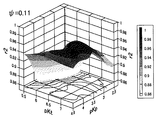
より具体的に、図6を用いて説明する。図6は、オープンセル方式の滴定結果から全アルカリ度ATの標準偏差を求め、当該標準偏差と全アルカリ度ATの平均値を示した図である。なお、図6において、K(BPB)は、対数表示(pK(BPB))で表してある。具体的には、pK(BPB)は-log(K(BPB))を表している。例えば、図6に示すように、pK(BPB)を変化させて、仮の全アルカリ度ATの標準偏差を求める。なお、図6の例では、pK(BPB)が3.5付近で標準偏差が最小になっていることが分かる。 This will be described more specifically with reference to FIG. FIG. 6 is a diagram showing a standard deviation of the total alkalinity AT from the titration result of the open cell method and showing an average value of the standard deviation and the total alkalinity AT . In FIG. 6, K (BPB) is expressed in logarithmic representation (pK (BPB) ). Specifically, pK (BPB) represents -log (K (BPB) ). For example, as shown in FIG. 6, the standard deviation of the provisional total alkalinity AT is obtained by changing pK (BPB) . In the example of FIG. 6, it can be seen that the standard deviation is minimized when pK (BPB) is around 3.5.
さらに、図7に示すように、pK(BPB)を変化させて、仮の全アルカリ度ATの標準偏差が最小になったときのpK(BPB)を用いれば、各滴定ポイントにおける試料溶液11の全アルカリ度ATは一定になる。言い換えると、全アルカリ度ATが一定になるpK(BPB)が最適解となり、このときの全アルカリ度ATが試料溶液11の真の全アルカリ度ATとなる。
Furthermore, as shown in FIG. 7, if pK (BPB) is changed and pK (BPB) when the standard deviation of the temporary total alkalinity AT is minimized is used, the
また、上述したように、e1(BPB)、e2(BPB)、e3(BPB)は、上記表1の実験条件より予め求められており、また、Rの値は各滴定ポイントで得られているので、pK(BPB)の最適解が求まれば、上記式(8)より最適解の水素イオン濃度を求めることができる。そして、結果として、各滴定ポイントにおける試料溶液11の最適解の水素イオン濃度をも求めることができる。
Further, as described above, e 1 (BPB) , e 2 (BPB) , and e 3 (BPB) are obtained in advance from the experimental conditions in Table 1 above, and the value of R is obtained at each titration point. Therefore, if the optimum solution of pK (BPB) is obtained, the hydrogen ion concentration of the optimum solution can be obtained from the above equation (8). As a result, the hydrogen ion concentration of the optimum solution of the
なお、ステップS17での処理を3回程度行うことにより、pK(BPB)の最適解は、ある値に収束し、例えば、図6の「●」は、最適解でpK(BPB)=3.545、AT=2391.2であると求めることができる。 Note that the optimal solution of pK (BPB) converges to a certain value by performing the process in step S17 about three times. For example, “●” in FIG. 6 is the optimal solution and pK (BPB) = 3. 545, A T = 2391.2.
以下、ステップS17での演算結果を示す。具体的には、以下の表2に演算結果を示す。なお、表2において、pK(BPB)の初期値は、pK(BPB)についての仮の値である。 Hereinafter, the calculation result in step S17 is shown. Specifically, the calculation results are shown in Table 2 below. In Table 2, the initial value of pK (BPB) is a temporary value for the pK (BPB).
なお、上記ステップS17で、全アルカリ度ATをpH3.0〜pH3.5の範囲において最も標準偏差が小さくなるようにして求めたのは、海水の場合、pH3.5を超えると試料溶液11(具体的には海水)に残留している炭酸(H2CO3)のH+の解離が存在し、またpH3.0を下回ると試料溶液11(具体的には海水)中のH+とSO4 2-が会合し、求める全アルカリ度ATに影響を与えるためである。
In step S17, the total alkalinity AT was determined so that the standard deviation was the smallest in the range of pH 3.0 to pH 3.5. In the case of seawater, the
また、以下、本実施形態に係る測定方法であるオープンセル方式により試料溶液11の全アルカリ度AT測定を行い、その再現性を検証した。結果を以下の表3に示す。
In addition, hereinafter, the total alkalinity AT measurement of the
表3に示すように、大変良好な結果であり、本発明に係る測定方法は、再現性に優れた測定方法であることがわかる。 As shown in Table 3, it is a very good result, and it can be seen that the measurement method according to the present invention is a measurement method with excellent reproducibility.
このように、本実施形態に係る測定方法によれば、pH電極を用いなくとも全アルカリ度ATを測定することができる。つまり、pH電極の維持管理の煩わしさを解消することができる。さらに、炭酸系の測定項目の測定値の主要な誤差要因であったpH電極のドリフトや感度の低下も起こることがない。従って、より簡易な方法で、精度良く試料溶液の全アルカリ度ATを測定することができる。 Thus, according to the measuring method according to the present embodiment, the total alkalinity AT can be measured without using a pH electrode. That is, the troublesome maintenance of the pH electrode can be eliminated. In addition, there is no possibility of pH electrode drift or sensitivity reduction, which is a major error factor in the measurement values of carbonic acid measurement items. Therefore, the total alkalinity AT of the sample solution can be accurately measured by a simpler method.
また、一方で、本実施形態に係る測定方法によれば、K(BPB)が未知であっても、当該K(BPB)の最適解を求めることもできる。さらに、K(BPB)の最適解を求めることができれば、酸を添加する前の試料溶液11のpHを計算することも可能となる。これにより、炭酸系の計算により、全炭酸濃度、二酸化炭素分圧も計算することができる。
On the other hand, according to the measurement method according to the present embodiment, even if K (BPB) is unknown, an optimal solution of K (BPB) can be obtained. Furthermore, if the optimum solution of K (BPB) can be obtained, the pH of the
一般的に、指示薬の解離定数は、当該指示薬が含有されている試料溶液の温度や塩分濃度によって大きく変化することが知られている。言い換えると、指示薬の解離定数は、当該指示薬が含有されている試料溶液の温度や塩分濃度が変化することによって、指示薬の解離定数も変化することになる。つまり、精度良く試料溶液の炭酸系の測定項目の測定値を得るためには、正確な指示薬の解離定数を予め求めておく必要がある。しかしながら、本発明に係る測定方法を用いれば、指示薬の解離定数を予め求めておく必要がなく、精度良く試料溶液の全アルカリ度ATを測定することができる。 In general, it is known that the dissociation constant of an indicator greatly changes depending on the temperature and salt concentration of a sample solution containing the indicator. In other words, the dissociation constant of the indicator also changes as the temperature and salt concentration of the sample solution containing the indicator change. That is, in order to obtain the measurement value of the carbonic acid measurement item of the sample solution with high accuracy, it is necessary to obtain an accurate indicator dissociation constant in advance. However, if the measurement method according to the present invention is used, it is not necessary to previously determine the dissociation constant of the indicator, and the total alkalinity AT of the sample solution can be measured with high accuracy.
なお、上述した例では、K(BPB)について、仮の値のパラメーターを設定した。しかしながら、これに限られず、例えば、K(BPB)が既知であれば、e1(BPB)、e2(BPB)、e3(BPB)について仮の値をパラメーターとして設定して、より具体的には、加えた指示薬の数の3倍以下のモル吸光係数の比(本実施形態では加えた指示薬は1つであるので、モル吸光係数を3つ、つまり、e1(BPB)、e2(BPB)、e3(BPB))をパラメーターとして設定して、上述した数値演算により最適解を求めることもできる。言い換えると、比色法の演算に関わるパラメーター、つまり試料溶液11の水素イオン濃度演算に関わるパラメーターの最適解を上述した数値演算により求めることもできる。
In the above-described example, a temporary parameter is set for K (BPB) . However, the present invention is not limited to this. For example, if K (BPB) is known, a temporary value is set as a parameter for e 1 (BPB) , e 2 (BPB) , e 3 (BPB) , and more specific. The ratio of the molar extinction coefficient that is three times or less the number of added indicators (in this embodiment, since there is one indicator added, there are three molar extinction coefficients, ie, e 1 (BPB) , e 2 (BPB) , e 3 (BPB) ) can be set as parameters, and an optimal solution can be obtained by the above-described numerical calculation. In other words, the optimum solution of the parameters related to the colorimetric calculation, that is, the parameters related to the hydrogen ion concentration calculation of the
上記の説明では、例えば、K(BPB)、e1(BPB)、e2(BPB)、e3(BPB)をそれぞれ固定値とし、[H']を求め、上記式(54)において、採水温度、滴定温度、酸の温度、サンプルの重さ、酸の重さ(滴定量)、酸濃度、サンプルの塩分濃度のうち、1つ以上を未知の値とし、パラメータとして動かし、そのときの全アルカリ度ATの標準偏差が最小となるように最適値を求めることが出来る。 In the above description, for example, K (BPB) , e 1 (BPB) , e 2 (BPB) , e 3 (BPB) are fixed values, and [H ′] is obtained, and is taken in the above equation (54). One or more of water temperature, titration temperature, acid temperature, sample weight, acid weight (titrated amount), acid concentration, sample salinity concentration are set as unknown values and moved as parameters. The optimum value can be obtained so that the standard deviation of the total alkalinity AT is minimized.
上述したように、炭酸の平衡定数、他の物質の平衡定数(K1、K2、KB、KSi、KNH3、KH2S、KS、KF、K1P、K2P、K3P、、BT、ST、FT、PT、SiT、NH3T、H2ST)は塩分濃度や温度によって、それぞれ、関係式が求められており、決められるものである。例えば、サンプルの重さ(測定開始前の試料溶液の重量m0)を未知数として、パラメータとして動かすことが出来、その時の全アルカリ度ATの標準偏差が最小となるように最適値を求めることが出来る。このようにすれば、予めサンプルの重さを秤量もしくはメスアップする必要がないので、大変、手間が省け、測定の簡便化ができる。 As described above, the equilibrium constant of carbonic acid, the equilibrium constant of other substances (K 1 , K 2 , K B , K Si , K NH3 , K H2S , K S , K F , K 1P , K 2P , K 3P , , B T , S T , F T , P T , Si T , NH 3T , and H 2 S T ), the relational expressions are respectively determined and determined depending on the salinity concentration and temperature. For example, the weight of the sample (weight m 0 of the sample solution before the start of measurement) can be moved as a parameter, and the optimum value is calculated so that the standard deviation of the total alkalinity AT at that time is minimized. I can do it. In this way, since it is not necessary to weigh or measure up the weight of the sample in advance, it is possible to save labor and simplify the measurement.
(第2の実施形態)
次に、第2の実施形態に係る測定方法として、クローズドセル方式(密閉型滴定)による炭酸系の測定項目の値の測定方法を説明する。なお、本実施形態の説明においても、図1に示した装置構成の概略図を参照しつつ、試料溶液11における炭酸系の測定項目の値の測定方法について、以下説明する。また、本実施形態においても、試料溶液11は、アルカリ度を有する溶液であれば特に限定されるものではないが、一例として、試料溶液11は海水と仮に想定して、以下説明する。
(Second Embodiment)
Next, as a measuring method according to the second embodiment, a method for measuring a value of a carbonic acid measurement item by a closed cell method (closed titration) will be described. In the description of the present embodiment, the method for measuring the value of the carbonic acid measurement item in the
なお、クローズドセル方式による測定では、上述したオープンセル方式による測定とは異なり、滴定により試料溶液11の全アルカリ度ATおよび全炭酸濃度CTをそれぞれ算出することができる。
In the measurement by closed-cell method, unlike the measurement by open cell method described above, the total alkalinity A T and the total carbonate concentration C T of the
図8は、クローズドセル方式による測定の流れを示したフローチャートである。なお、一般的にクローズドセル方式による測定は、比較的広い範囲のpHにおいて炭酸系の測定項目の値を測定するため、試料溶液11中に2種の酸塩基指示薬(仮に指示薬Aおよび指示薬Bと称す)を含有させる場合もあるが、1種の指示薬を含有させる場合もある。
FIG. 8 is a flowchart showing a flow of measurement by the closed cell method. In general, in the measurement by the closed cell method, in order to measure the value of the measurement item of carbonic acid in a relatively wide range of pH, two acid-base indicators (provisional indicator A and indicator B) are included in the
なお、試料溶液11に含有させる2種の指示薬は、特に限定されるものではないが、一例として、指示薬Aとしてブロモフェノールブルー(以下、BPBと称すことがある)および指示薬Bとしてブロモチモールブルー(以下、BTBと称すことがある)を含有させる場合について説明する。なお、ブロモクレゾールとフェノールレッドなど、いくつかの指示薬を組み合わせも考え得る。
The two types of indicators contained in the
図8のステップS21に示すように、処理手段13は滴定を開始、試料溶液11に酸を滴下しつつ、Rの値の測定を行う。具体的には、例えば、図1に示した滴下手段14は、処理手段13からの指示に従い予め定められた量および予め定められた間隔で酸溶液10を試料溶液11に滴下する。なお、同時に、Rの値は、吸光度測定手段12が試料溶液11に光を照射し、当該試料溶液11の光の吸収の強さを測定することにより、処理手段13が求める。
As shown in step S <b> 21 of FIG. 8, the processing means 13 starts titration and measures the value of R while dropping the acid into the
なお、上述したように、R=Abs1/Abs2であるので、例えば、波長450nmにおける吸光度をAbs1とし、波長592nmにおける吸光度をAbs2とする(図3参照)。そして、試料溶液11に酸溶液10が滴下されるごとに処理手段14はRの値を測定し、酸溶液10が滴下されるごとに得られたRの値を、例えば、処理手段14に一時的に記憶しておく。
As described above, since R = Abs 1 / Abs 2 , for example, the absorbance at a wavelength of 450 nm is Abs 1 and the absorbance at a wavelength of 592 nm is Abs 2 (see FIG. 3). Then, each time the
図2のステップS22において、処理手段13は、パラメーターの初期値を用いて、仮の[H']を求め、仮のpHを計算し、試料溶液11のpHは、3を下回ったか否かを判断する。そして、処理手段13は、当該ステップS22の判断を肯定した場合(YES)、次のステップS23に処理を進める。一方、処理手段13は、当該ステップS22の判断を否定した場合(NO)、ステップS21に処理を戻し、引き続き滴定を行う。
In step S22 of FIG. 2, the processing means 13 obtains a temporary [H ′] using the initial value of the parameter, calculates the temporary pH, and determines whether the pH of the
ステップS23において、処理手段13は、追加の滴定を行う。なお、当該ステップS23にて行われる処理は、図2のステップS17で説明したので省略する。 In step S23, the processing means 13 performs additional titration. The processing performed in step S23 has been described in step S17 in FIG.
ここで、一例として、図9にクローズドセル方式による測定による測定結果の一例を示す。なお、測定条件は以下の表4の通りである。 Here, as an example, FIG. 9 shows an example of the measurement result by the measurement by the closed cell method. The measurement conditions are as shown in Table 4 below.
なお、上記表4において、酸(塩酸)の濃度は、0.1Mである。また、上記表4において、e1(BPB)、e2(BPB)、e3(BPB)、e1(BTB)、e2(BTB)、e3(BTB)は、それぞれモル吸光係数の比であり、e1(BPB)=592εHA/450εHA、e2(BPB)=592εA-/450εHA、e3(BPB)=450εA-/450εHA、e1(BTB)=592εHB/450εHB、e2(BTB)=592εB-/450εHB、e3(BTB)=450εB-/450εHBのようにそれぞれ表される。 In Table 4 above, the concentration of acid (hydrochloric acid) is 0.1M. In Table 4 above, e 1 (BPB) , e 2 (BPB) , e 3 (BPB) , e 1 (BTB) , e 2 (BTB) , e 3 (BTB) are the molar extinction coefficient ratios, respectively. E 1 (BPB) = 592 ε HA / 450 ε HA , e 2 (BPB) = 592 ε A- / 450 ε HA , e 3 (BPB) = 450 ε A- / 450 ε HA , e 1 ( BTB) = 592 ε HB / 450 ε HB , e 2 (BTB) = 592 ε B− / 450 ε HB , e 3 (BTB) = 450 ε B− / 450 ε HB , respectively.
図9は、測定時間、酸の滴定量および吸光度の関係を示した図である。具体的には、図9は、横軸を測定時間、縦軸を酸(塩酸)の滴定量(図9上)および吸光度(図9下)で示してある。図9に示すように、予め定められた間隔で試料溶液11に酸(塩酸)が滴下されることによって、波長450nmの吸光度が上昇し、波長592nmの吸光度が減少する。
FIG. 9 is a graph showing the relationship between measurement time, acid titer and absorbance. Specifically, in FIG. 9, the horizontal axis indicates the measurement time, and the vertical axis indicates the acid (hydrochloric acid) titration (upper FIG. 9) and absorbance (lower FIG. 9). As shown in FIG. 9, when acid (hydrochloric acid) is dropped into the
図8の説明に戻って、ステップS24において、図1の処理手段13は、演算を行い、図8のフローチャートの処理を終了する。 Returning to the description of FIG. 8, in step S <b> 24, the processing means 13 of FIG. 1 performs an operation and ends the processing of the flowchart of FIG. 8.
ここで上述したように、各滴定ポイントにおけるRの値は上記ステップS21で算出されている。そこで、処理手段13は、各滴定ポイントにおける試料溶液11のpHの演算を行う。具体的には、処理手段13は、各滴定ポイントで得られたRの値を用い、各滴定ポイントにおける試料溶液11の水素イオン濃度を式(29)に基づいて求める。なお、式(29)において、e1(BPB)、e2(BPB)、e3(BPB)、e1(BTB)、e2(BTB)、e3(BTB)は、例えば、上記表4の実験条件より予め求められており、また、Rの値は各滴定ポイントで得られている。そして、K(BPB)、K(BTB)、ψについて、仮の値のパラメーターを設定して、当該式(29)を用いて、各滴定ポイントにおける試料溶液11の仮の水素イオン濃度を[H']を算出する。
As described above, the value of R at each titration point is calculated in step S21. Therefore, the processing means 13 calculates the pH of the
なお、指示薬が1種の場合は、上述の第1の実施形態での説明(オープンセル方式での説明)と同様にして、上記式(8)を用いればよい。 In addition, when there is only one kind of indicator, the above formula (8) may be used in the same manner as described in the first embodiment (the description in the open cell system).
具体的には、例えば、処理手段13は、各滴定ポイントで得られたRの値を用い、各滴定ポイントにおける試料溶液11のpHを上記式(29)に基づいて求める。例えば、上記式(29)において、e1(BPB)、e2(BPB)、e3(BPB)、e1(BTB)、e2(BTB)、e3(BTB)は、上記表4の実験条件より予め求められており、また、Rの値は各滴定ポイントで得られている。そして、上記式(29)において、例えば、K(BPB)、K(BTB)、ψについて、仮の値のパラメーターをそれぞれ設定して、当該式(29)を用いて、各滴定ポイントにおける試料溶液11の仮の水素イオン濃度を[H']を求める。
Specifically, for example, the processing means 13 uses the value of R obtained at each titration point, and obtains the pH of the
なお、図10に酸(塩酸)の滴定量、各滴定ポイントでの試料溶液11のRの値およびpHの関係を示した。
FIG. 10 shows the relationship between the titration amount of acid (hydrochloric acid), the R value of the
図10において、「●」はpH>3における各滴定ポイントで得られたRの値、「○」はpH<3における最適化の計算に用いなかったRの値である。なお、「×」は式(28)に基づいて求めた各滴定ポイントにおけるpHであるが、上記表4の実験条件より予め求められているe1(BPB)、e2(BPB)、e3(BPB)、e1(BTB)、e2(BTB)、e3(BTB)、後述するK(BPB)、K(BTB)、ψの最適解をそれぞれ用いている。 In FIG. 10, “●” is the R value obtained at each titration point at pH> 3, and “◯” is the R value not used in the optimization calculation at pH <3. “X” is the pH at each titration point determined based on the equation (28), and e 1 (BPB) , e 2 (BPB) , e 3 determined in advance from the experimental conditions in Table 4 above. (BPB) , e 1 (BTB) , e 2 (BTB) , e 3 (BTB) , and optimal solutions for K (BPB) , K (BTB) , and ψ described later are used.
そして、求めた仮の水素イオン濃度[H']を用いて、x軸に上記式(51)での算出値を、y軸に上記式(52)での算出値を各滴定ポイントごとにプロットすると、図11に示すようなグラフが得られる。なお、図11において、初期値とは、K(BPB)、K(BTB)、ψに仮の値を設定して、各滴定ポイントごとにx[H']とy[H']との関係をプロットしたものである。 Then, using the calculated temporary hydrogen ion concentration [H ′], the calculated value in the above equation (51) is plotted on the x axis and the calculated value in the above equation (52) is plotted on the y axis for each titration point. Then, a graph as shown in FIG. 11 is obtained. In FIG. 11, the initial value is a relationship between x [H '] and y [H'] for each titration point by setting temporary values for K (BPB) , K (BTB) , and ψ. Are plotted.
このプロットを用いて、直性性が最も高くなるように、例えば、非線形最小二乗法(ニートン法、ガウス・ニュートン法、パウエルの最小二乗法など)により仮の値のパラメーターの最適解をそれぞれ求める。具体的には、直線性を評価するには相関係数rを求めればよく、以下の式(55)において、r2が最大になる各パラメーターの最適解をそれぞれ求めればよい。 Using this plot, for example, find the optimal solution for the parameter of the temporary value by the nonlinear least square method (Neton method, Gauss-Newton method, Powell's least square method, etc.), for example, so that the straightness is the highest . Specifically, in order to evaluate linearity, the correlation coefficient r may be obtained, and in the following equation (55), the optimum solution for each parameter that maximizes r 2 may be obtained.
なお、一例として、K(BPB)、K(BTB)、ψについて、仮の値のパラメーターをそれぞれ設定して、可変させた時のr2の値を図12〜図14に示す。なお、以下の説明において、pK(BPB)=-log(K(BPB))、pK(BTB)=-log(K(BTB))である。 As an example, FIGS. 12 to 14 show the values of r 2 when temporary parameter values are set and varied for K (BPB) , K (BTB) , and ψ, respectively. In the following description, pK (BPB) = − log (K (BPB) ) and pK (BTB) = − log (K (BTB) ).
図12〜図14は、一例として、pK(BPB)、pK(BTB)、ψをパラメーターとして設定し、当該各パラメーターを変化させたときのr2の値を示したものである。なお、パラメータの最適解を求める方法としての非線形最小二乗法のアルゴリズムとして、ニュートン法、ガウス・ニュートン法、パウエルの最小二乗法などがあるが、マイクロソフト社製の表計算ソフト「Excel」ではソルバー機能により、最適解を求めると、最適解は、それぞれ、pK(BPB)=3.553、pK(BTB)=6.5504、φ=0.1303、r2=1.000であった。 FIGS. 12 to 14 show values of r 2 when, for example, pK (BPB) , pK (BTB) , and ψ are set as parameters and the parameters are changed. In addition, there are Newton's method, Gauss-Newton's method, Powell's least square method, etc. as nonlinear least square algorithm as a method for obtaining the optimal solution of parameters, but the solver function is in Microsoft spreadsheet software "Excel". Thus, the optimum solution was found to be pK (BPB) = 3.553, pK (BTB) = 6.5504, φ = 0.1303, and r 2 = 1.000, respectively.
ここで、上記式(53)より、図11において、全炭酸濃度CTは、一定量の酸滴下量に対する変化量(つまり、直線近似式の傾き)から得られる。一方、全アルカリ度ATは、直線近似式の切片から得られる。 Here, from the above equation (53), in FIG. 11, the total carbonic acid concentration CT is obtained from the amount of change with respect to a certain amount of acid dripping (that is, the slope of the linear approximation equation). On the other hand, the total alkalinity AT is obtained from the intercept of the linear approximation formula.
以下、ステップS24での演算結果を表5に示す。なお、表5において、pK(BPB)、pK(BTB)、ψの初期値は、仮の値である。 Hereinafter, Table 5 shows the calculation result in step S24. In Table 5, the initial values of pK (BPB) , pK (BTB) , and ψ are provisional values.
表5に示すように、pK(BPB)、pK(BTB)、ψの最適解が求まれば、試料溶液11の全アルカリ度ATおよび全炭酸濃度CTが求まる。そして、上述したように、e1(BPB)、e2(BPB)、e3(BPB)、e1(BTB)、e2(BTB)、e3(BTB)は、上記表4の実験条件より予め求められており、また、Rの値は各滴定ポイントで得られているので、pK(BPB)、pK(BTB)、ψの最適解が求まれば、上記式(28)より最適解の水素イオン濃度を求めることができる。そして、結果として、各滴定ポイントにおける試料溶液11のpHをも求めることができるとともに、試料溶液11のpHを求めることもできる。
As shown in Table 5, pK (BPB), pK (BTB), if optimal solution ψ is determined, obtained is the total alkalinity A T and the total carbonate concentration C T of the
また、以下、本実施形態に係る測定方法であるクローズドセル方式により試料溶液11の全アルカリ度ATおよび全炭酸濃度CTの測定を行い、その再現性を検証した。結果を以下の表6に示す。
In the following, the closed-cell method is a measurement method according to the present embodiment performs the measurement of total alkalinity A T and the total carbonate concentration C T of the
表6に示すように、大変良好な結果であり、本発明に係る測定方法は、再現性に優れた測定方法であることがわかる。このようにして、クローズド法により、全アルカリ度と全炭酸が求まるとともに、パラメーターの最適解よりサンプル(試料溶液11)のpHが求められ、炭酸系の平衡計算式である、式(36)〜(39)を用いれば、二酸化炭素分圧も計算できる。(例えば、「DOE(1994)Handbook of methods for the analysis of the various parameter of the carbon dioxide system in sea water. Version 2, A.G.Dickson & C.Goyet, eds.ORNL/CDIAC-74」参照)
As shown in Table 6, it is a very good result, and it can be seen that the measurement method according to the present invention is a measurement method with excellent reproducibility. In this way, the total alkalinity and total carbonic acid are obtained by the closed method, and the pH of the sample (sample solution 11) is obtained from the optimal solution of the parameters. If (39) is used, the carbon dioxide partial pressure can also be calculated. (For example, see "DOE (1994) Handbook of methods for the analysis of the various parameter of the carbon dioxide system in sea water.
このように、本実施形態に係る測定方法によれば、上述した第1の実施形態に係る測定方法と同様の効果を得ることができる。 Thus, according to the measurement method according to the present embodiment, the same effects as those of the measurement method according to the first embodiment described above can be obtained.
また、一方で、本実施形態に係る測定方法によれば、K(BPB)、K(BTB)、ψが未知であっても、当該K(BPB)、K(BTB)、ψのそれぞれの最適解を求めることもできる。 On the other hand, according to the measurement method according to the present embodiment, even if K (BPB) , K (BTB) , and ψ are unknown, the optimum of each of K (BPB) , K (BTB) , and ψ You can also find a solution.
なお、上述した例では、K(BPB)、K(BTB)、ψについて、仮の値のパラメーターをそれぞれ設定した。しかしながら、これに限られず、例えば、K(BPB)、K(BTB)、ψ、e1(BPB)、e2(BPB)、e3(BPB)、e1(BTB)、e2(BTB)、e3(BTB)それぞれのうち、何れか3つについて仮の値のパラメーターを設定して、最適解を求めることもできる。 In the above-described example, temporary value parameters are set for K (BPB) , K (BTB) , and ψ. However, it is not limited to this, for example, K (BPB) , K (BTB) , ψ, e 1 (BPB) , e 2 (BPB) , e 3 (BPB) , e 1 (BTB) , e 2 (BTB) , E 3 (BTB) , the optimal solution can be obtained by setting parameters of temporary values for any three of them.
例えば、K(BPB)、K(BTB)、e1(BPB)、e2(BPB)、e3(BPB)、e1(BTB)、e2(BTB)、e3(BTB)を固定値として、サンプルの重さ、塩酸の重さ(滴定量)、酸濃度、塩分濃度、温度、をパラメータとすることも出来る。クローズド法の場合は、同様の測定を行い、K(BPB)をある固定値として、決めてしまい、例えば、サンプルの重さ(測定開始前の試料溶液の重量m0)を未知数として、パラメータとして式(53)を満たすように、同様に、非線形最小二乗法で、当該滴定ポイントの仮の全アルカリ度ATの標準偏差を最小にするように、上記サンプルの重さを求めればよい。以下、その他のパラメータについても、未知にするパラメータ以外のものを、固定にして、式(54)を満たすように全アルカリ度ATの標準偏差を最小にするようにパラメータを動かして非線形最小二乗法により求めればよい。 For example, K (BPB) , K (BTB) , e1 (BPB) , e2 (BPB) , e3 (BPB) , e1 (BTB) , e2 (BTB) , e3 (BTB) are fixed values As parameters, the sample weight, hydrochloric acid weight (titer), acid concentration, salinity concentration, and temperature can be used as parameters. In the case of the closed method, the same measurement is performed, and K (BPB) is determined as a fixed value. For example, the weight of the sample (the weight m 0 of the sample solution before the start of measurement) is set as an unknown parameter. Similarly, the weight of the sample may be obtained so as to minimize the standard deviation of the temporary total alkalinity AT of the titration point by the nonlinear least square method so as to satisfy the equation (53). Hereinafter, with respect to other parameters, parameters other than the unknown parameters are fixed, and the parameters are moved so as to minimize the standard deviation of the total alkalinity AT so as to satisfy the equation (54). What is necessary is just to obtain | require with a multiplication.
つまり、クローズドセル法についても、測定は同様に行い、K(BPB)、K(BTB)、ψについて固定値に決めてしまい、サンプルの重さをパラメータとして式(29)と式(53)各滴定ポイントごとにプロットし、非線形最小二乗法で、r2が最大になるように、サンプルの重さを求めればよい。その他のパラメータについても、未知にするパラメータ以外のものを、固定にして、r2が最大になるようにパラメータを動かして非線形最小二乗法で、求めればよい。 That is, in the closed cell method, the measurement is performed in the same manner, and K (BPB) , K (BTB) , and ψ are determined to be fixed values, and each of the expressions (29) and (53) is set with the weight of the sample as a parameter. plotted for each titration point, a non-linear least squares method, so that r 2 is maximized, it may be obtained the weight of the sample. Other parameters may be obtained by a non-linear least square method by fixing parameters other than the unknown parameters and moving the parameters so that r 2 is maximized.
さらに、上述した例では、試料溶液11中に2種の酸塩基指示薬(具体的には、指示薬Aとしてブロモフェノールブルー、および指示薬Bとしてブロモチモールフェノール)を含有させたが、酸塩基指示薬は2種に限られない。つまり、3種以上の酸塩基指示薬を試料溶液11中に含有させてもよい。例えば、指示薬Aと指示薬Bとの加えて指示薬Cを試料溶液11中に含有させた場合、ある波長λ1および波長λ2における非解離形(HC)および解離形(A-)のモル吸光係数をそれぞれ1εHC、1εC-、2εHC、2εC-として、モル吸光係数の比をそれぞれ、e1(C)=1εHC/2εHC、e2(C)=1εC-/2εHC、e3(C)=2εA-/2εHAとすることもできる。
Furthermore, in the above-described example, two kinds of acid-base indicators (specifically, bromophenol blue as the indicator A and bromothymolphenol as the indicator B) are included in the
次に、図面を参照しつつ、本発明に係る測定方法を用いた装置(以下、単に装置と称すことがある)の各実施形態について説明する。 Next, embodiments of an apparatus using a measurement method according to the present invention (hereinafter sometimes simply referred to as an apparatus) will be described with reference to the drawings.
(第3の実施形態)
図15は、本実施形態に係る装置の構成の一例を示す図である。本実施形態に係る装置は、試料溶液に直接、酸を滴下しながら、当該試料溶液の吸光度を測定するものである。図15に示すように、本実施形態に係る装置は、試料瓶22、シリンジポンプ24、酸貯留タンク23、スターラー33、処理部29、温度計34等を含む。
(Third embodiment)
FIG. 15 is a diagram illustrating an example of the configuration of the apparatus according to the present embodiment. The apparatus according to the present embodiment measures the absorbance of the sample solution while dropping acid directly into the sample solution. As shown in FIG. 15, the apparatus according to this embodiment includes a
具体的には、図15に示すように、まず、酸貯留タンク23からの酸(例えば、塩酸)は、シリンジポンプ24によって酸ノズル35を通り、試料瓶22に入れられている測定されるべき試料溶液21(例えば、海水)に滴下される(図15の矢印26)。次いで、光源25から出射された光は、試料瓶22を透過し、検出器28によって検出される。そして、検出器28は、当該検出器28に入射した光を電気信号に変換し、処理部29(具体的にはプリアンプ30)に出力する。その後、電気信号は、インターフェイス31を介してCPU(中央処理装置)32に出力され、当該CPU32によって数値演算(pHやパラメーターの最適解の演算、炭酸炭酸系の測定項目の測定等)が行われる。
Specifically, as shown in FIG. 15, first, the acid (for example, hydrochloric acid) from the
シリンジポンプ24は、酸貯留タンク23に貯留される酸を吸引し、試料瓶22内の試料溶液21に酸を滴下する滴下手段である。なお、炭酸系の測定項目の値の測定においては、高精度の滴定が必要とされるので、微小量の吸引、吐出に優れ高精度で送液制御が可能なマイクロシリンジポンプやオートビュレットを用いることが好ましい。
The
酸貯留タンク23には、滴定用の酸が貯留される。タンクとしては、貯留する酸濃度が変化しないように密閉性を備えるとともに酸による腐食に耐性を有するものであればよい。
The
スターラ33は、マグネティックスターラなどであり、試料瓶22内に試料溶液21とともに投入された回転子36を所定の回転速度で回転させる。そして、スターラ33によって、回転子36が回転することで、当該試料溶液21は撹拌され、滴下された酸と試料溶液21中の中和反応を促進することができる。
The
処理部29は、プリアンプ30、インターフェイス31、およびCPU32等を含み、シリンジポンプ24の滴定制御、スターラ33の回転制御、光源25の出力制御等を行う。具体的には、温度計34および検出器28からの電気信号(出力信号)は、プリアンプ30で増幅、調整され、インターフェイス31を介してCPU32に入力される。そして、CPU32は、これらの電気信号に基づいて、シリンジポンプ24の滴下量やスターラ4の回転速度を調整する。
The
光源25は、発光ダイオード(Light Emitting Diode:以下単にLEDと称すことがある)、タングステンランプ、キセノンランプなどである光の出射源である。なお、LED、タングステンランプ、キセノンランプなどから出射された光は、光源25内に備わっている、図示しないスペクトロメータ(分光器)で、分光され、所望の波長の光が出射されるようになっている。検出器28は、例えば、フォトダイオードなどによって構成され、試料瓶22を透過した光を電気信号に変換する。また、試料瓶22は、光源25からの光が透過できるように透明ガラス、石英等により作製されたものを用いればよい。
The
なお、光源25および検出器28は、上述したように、本発明に係る測定方法を用いた装置の概略図(図1参照)において、吸光度測定手段12の一例に相当する。ここで、吸光度測定手段12の第1および第2の変形例を説明する。
As described above, the
まず、吸光度測定手段12の第1の変形例を説明する。図16は、第1の変形例に係る吸光度測定手段12を含む装置構成の一例を示す図である。以下、図16を参照しつつ、第1の変形例に係る吸光度測定手段12を含む装置構成の一例について説明する。なお、図16の説明において、図15で示した構成と同様の構成については同一の参照符号を付して、説明は省略する。
First, a first modification of the
図16に示すように、吸光度測定手段12の第1の変形例は、光源25、検出器28、光ファイバーセル37を含む。つまり、試料溶液21の吸光度は、光源25と、検出器28と、光ファイバーセル37とを用いることによって測定される。なお、後述より明らかとなるが、光源25には、当該光源25から出射された光を光ファイバーセル37内に投光できるように、投光用光ファイバー38が接続されている。一方、検出器28にも、光源25から出射された光を光ファイバーセル37内で受光できるように受光用ファイバー39が接続されている。ここで、光ファイバーセルの拡大図を示す。
As shown in FIG. 16, the first modification of the
図17は、図16の破線aで囲んだ部分を拡大し、光ファイバーセル37の内部を示した図である。図17に示すように、光ファイバーセル37内部には、光源25に接続されている投光用光ファイバー38、および検出器28に接続されている受光用光ファイバー39が備わっている。なお、光ファイバーセル37内において、投光用光ファイバー38および受光用光ファイバー39の先端にはミラー40が備わっているため、投光用光ファイバー38から出射された光をミラー40で反射させ、受光用光ファイバー39で受光する。このようにしても、試料溶液21の吸光度を測定することもできる。
FIG. 17 is an enlarged view of the portion surrounded by the broken line a in FIG. 16 and shows the inside of the
次に、吸光度測定手段12の第2の変形例を説明する。図18は、第2の変形例に係る吸光度測定手段12を含む装置構成の一例を示す図である。以下、図18を参照しつつ、第2の変形例に係る吸光度測定手段12を含む装置構成の一例について説明する。なお、図18の説明において、図15で示した構成と同様の構成については同一の参照符号を付して、説明は省略する。
Next, a second modification of the
図18に示すように、吸光度測定手段12の第2の変形例は、光源25と、検出器28と、吸光度測定セル41と、Aポンプ42とを含む。つまり、試料溶液21の吸光度は、光源25と、検出器28と、吸光度測定セル41と、Aポンプ42とを用いることによって測定される。
As shown in FIG. 18, the second modification of the
なお、図18に示すように、吸光度測定セル41は、例えば、透明ガラスや石英等から作製される管路43を備えている。この管路43に試料溶液21を流過させ、流過している試料溶液21に光源25から出射された光を透過させる。そして、管路43を透過した光を検出器28によって検出することによって吸光度を測定する。このようにしても、試料溶液21の吸光度を測定することもできる。
As shown in FIG. 18, the
なお、試料溶液21は、一端が当該試料溶液21中に浸され、他端が管路43接続されているA1ノズル44を用いて、例えば、Aポンプ42によって管路43に送液される。そして、測定後の試料溶液21は、一端が当該試料溶液21中に浸され、他端が管路43接続されているA2ノズル45によって、試料瓶22に排水されるようになっている。
The
(第4の実施形態)
次に、図面を参照しつつ、本発明に係る測定方法を用いた装置(以下、単に装置と称すことがある)の他の実施形態について説明する。図19は、本実施形態に係る装置の構成の一例を示す図である。なお、以下の説明において、図15で示した構成と同様の構成については同一の参照符号を付して、説明は省略する。
(Fourth embodiment)
Next, another embodiment of an apparatus using the measurement method according to the present invention (hereinafter sometimes simply referred to as an apparatus) will be described with reference to the drawings. FIG. 19 is a diagram illustrating an example of the configuration of the apparatus according to the present embodiment. In the following description, the same components as those shown in FIG. 15 are denoted by the same reference numerals, and the description thereof is omitted.
本実施形態に係る装置は、試料溶液と酸/指示薬混合溶液とを混合し、流れ分析法によって、混合溶液の吸光度を測定するものである。図19に示すように、本実施形態に係る装置は、試料溶液供給源46、Bポンプ47、酸/指示薬混合溶液供給源48、Cポンプ49、ミキシングコイル50、吸光度測定セル41、光源25、および検出器28を含む。また、図示は省略したが、光源25および検出器28は、処理部29に接続されている。
The apparatus according to the present embodiment mixes a sample solution and an acid / indicator mixed solution, and measures the absorbance of the mixed solution by a flow analysis method. As shown in FIG. 19, the apparatus according to this embodiment includes a sample
具体的には、図19に示すように、試料溶液46は、Bポンプ47によって、予め定められた流量(RaB)で送液される。なお、試料溶液46は、容器に収納されている場合もあるし、容器を用いずに、フィールドで海水をBポンプ47で採水するとともに送液される場合もある。
Specifically, as shown in FIG. 19, the
一方、酸/指示薬混合溶液供給源48中の酸/指示薬混合溶液は、Cポンプ49によって、当該酸/指示薬混合溶液供給源48から予め定められた流量(RaC)で送液される。
On the other hand, the acid / indicator mixed solution in the acid / indicator mixed
そして、試料溶液46は、Bポンプ47とミキシングコイル50との間のB管路51によって、当該ミキシングコイル50に送液される。同様に、酸/指示薬混合溶液供給源48中の酸/指示薬混合溶液は、Cポンプ49とミキシングコイル50との間のC管路52によって、当該ミキシングコイル50に送液される。その後、試料溶液および酸/指示薬混合溶液は、ミキシングコイル50を流過することによって充分に混合される。さらに、ミキシングコイル50を流過した試料溶液および酸/指示薬混合溶液の吸光度は、光源25と、検出器28と、吸光度測定セル41とによって測定される。
Then, the
なお、例えば、Bポンプ47およびCポンプ49は、図示しない処理部29によって制御され、試料溶液供給源46と、酸/指示薬混合溶液供給源48中の酸/指示薬混合溶液との混合比率を変化させてもよい。すなわち、図示しない処理部29は、試料溶液の送液量と酸/指示薬混合溶液の送液量との比率Ra{=(RaB)/(RaC)}を変化させてもよい。
For example, the
例えば、上記比率Ra、つまり、サンプルの重さm0と塩酸の滴定量mとの比をパラメータとすることも出来る。例えば、比率Raを未知数として、パラメータとして、式(54)において、非線形最小二乗法で当該滴定ポイントの仮の全アルカリ度ATの標準偏差を最小にするように、上記比率Raを求めればよい。また、上記比率Raをパラメータとして式(29)と式(53)とを用い、式(55)において非線形最小二乗法でr2が最大になるように、上記比率Raを求めればよい。 For example, the ratio Ra, that is, the ratio between the weight m 0 of the sample and the titration amount m of hydrochloric acid can be used as a parameter. For example, the ratio Ra may be obtained by setting the ratio Ra as an unknown and using the nonlinear least square method to minimize the standard deviation of the temporary total alkalinity AT of the titration point in Equation (54) as a parameter. . Further, using the ratio Ra as a parameter, Expression (29) and Expression (53) are used, and the ratio Ra may be obtained so that r 2 is maximized by the nonlinear least square method in Expression (55).
(第5の実施形態)
次に、図面を参照しつつ、本発明に係る測定方法を用いた装置(以下、単に装置と称すことがある)の他の実施形態について、さらに説明する。図20は、本実施形態に係る装置の構成の一例を示す図である。なお、以下の説明において、図15および図19で示した構成と同様の構成については同一の参照符号を付して、説明は省略する。
(Fifth embodiment)
Next, another embodiment of a device using the measurement method according to the present invention (hereinafter sometimes simply referred to as a device) will be further described with reference to the drawings. FIG. 20 is a diagram illustrating an example of the configuration of the apparatus according to the present embodiment. In the following description, the same components as those shown in FIGS. 15 and 19 are denoted by the same reference numerals, and the description thereof is omitted.
本実施形態に係る装置は、試料溶液、酸溶液、および指示薬を混合し、流れ分析法によって、混合溶液の吸光度を測定するものである。図20に示すように、本実施形態に係る装置は、試料溶液46、Bポンプ47、酸供給源53、Dポンプ55、指示薬供給源54、Eポンプ56、ミキシングコイル50、吸光度測定セル41、光源25、および検出器28を含む。また、図示は省略したが、光源25および検出器28は、処理部29に接続されている。
The apparatus according to the present embodiment mixes a sample solution, an acid solution, and an indicator, and measures the absorbance of the mixed solution by a flow analysis method. As shown in FIG. 20, the apparatus according to this embodiment includes a
具体的には、図19に示すように、試料溶液46は、Bポンプ47によって、予め定められた流量(RaB)で送液される。また、酸供給源53中の酸は、Dポンプ55によって、当該酸供給源53から予め定められた流量(RaD)で送液される。さらに、指示薬供給源54中の指示薬は、Eポンプ56によって、当該指示薬供給源54から予め定められた流量(RaE)で送液される。
Specifically, as shown in FIG. 19, the
そして、試料溶液46は、Bポンプ47とミキシングコイル50との間のB管路51によって、当該ミキシングコイル50に送液される。また、酸供給源53中の酸は、Dポンプ55とミキシングコイル50との間のD管路57によって、当該ミキシングコイル50に送液される。さらに、指示薬供給源54中の指示薬は、Eポンプ56とミキシングコイル50との間のE管路58によって、当該ミキシングコイル50に送液される。そして、試料溶液、酸、指示薬は、ミキシングコイル50を流過することによって充分に混合され、混合溶液となる。その後、ミキシングコイル50を流過した混合溶液の吸光度は、光源25と、検出器28と、吸光度測定セル41とによって測定される。
Then, the
なお、例えば、Bポンプ47、Dポンプ55、Eポンプ56は、図示しない処理部29によって制御され、ミキシングコイル50における試料溶液、酸、指示薬の混合比率を変化させてもよい。つまり、例えば、上記比率Raをパラメータとすることも出来る。例えば、比率Raを未知数として、パラメータとして、式(54)において、非線形最小二乗法で当該滴定ポイントの仮の全アルカリ度ATの標準偏差を最小にするように、上記比率Raを求めればよい。また、上記比率Raをパラメータとして式(29)と式(53)とを用い、式(55)において、各滴定ポイントごとにプロットし非線形最小二乗法で、r2が最大になるように、上記比率Raを求めればよい。
For example, the
以上説明したように、上述の第3〜第5の実施形態に係る装置によれば、本発明に係る測定方法を用いることができる。また、上述の第3〜第5の実施形態に係る装置は、試料溶液に直接、酸を滴下しながら、当該試料溶液の吸光度を測定するものである。つまり、上述の第3〜第5の実施形態に係る装置は、滴定から測定まで1つの容器で行うことができるので、例えば、試料溶液に酸を滴下する度に当該試料溶液を別の分光光度計で測定する場合と比べて測定に要する時間を短縮することができる。 As described above, according to the apparatuses according to the third to fifth embodiments described above, the measurement method according to the present invention can be used. Moreover, the apparatus which concerns on the above-mentioned 3rd-5th embodiment measures the light absorbency of the said sample solution, dripping an acid directly to a sample solution. That is, since the apparatus according to the third to fifth embodiments described above can be performed in one container from titration to measurement, for example, each time the acid is dropped on the sample solution, the sample solution is subjected to another spectrophotometry. The time required for measurement can be shortened compared with the case of measuring with a meter.
さらに、上述の第4および第5の実施形態に係る装置によれば、測定に要する各溶液(例えば、試料溶液、酸、指示薬)は少量で済ませることができる。 Furthermore, according to the apparatuses according to the fourth and fifth embodiments described above, each solution (for example, sample solution, acid, indicator) required for measurement can be made in a small amount.
なお、上述した光源25は、光の出射源として一般的なタングステンランプ、キセノンランプなどの他にLED等を用いることが可能である。
The
図21は、上述した光源25の光の出射源としてLEDを用いた例を示した図である。例えば、図21に示すように、光源25の光の出射源として、第1の発光体59、第2の発光体60を備えている場合を仮に想定する。そして、例えば、第1の発光体59が出射する光の波長は、指示薬の非解離形(酸フォーム)由来のピークが得られる波長であるとし、第2の発光体60が出射する光の波長は、指示薬の解離形(アルカリフォーム)由来のピークが得られる波長であるとする。このようにすることで、光源25にスペクトロメータ(分光器)を備えなくともよいので、光源25は簡易な構成で済む。なお、外見上は1つのパッケージの中に2つ以上の発光体を収納したLEDも市販されている。
FIG. 21 is a diagram showing an example in which an LED is used as the light emission source of the
つまり、それぞれ所望の波長の光を出射することのできる発光体を少なくとも2つ以上、光源25に備え、当該発光体をそれぞれ別々に点灯させ、検出器28で光の強さを測定することにより、試料溶液21の吸光度を測定することができる。
That is, by providing at least two or more light emitters that can emit light of a desired wavelength in the
なお、それぞれ所望の波長の光を出射することのできる発光体を少なくとも2つ以上備えた光源25は、本発明に係る測定方法を用いた装置の光源として用いる場合に限られない。つまり、それぞれ所望の波長の光を出射することのできる発光体を少なくとも2つ以上備えた光源25と、光の強さを測定することのできる検出器とによって、例えば、海水だけではなく種々溶液の吸光度を測定することができる。
Note that the
以上、本発明を詳細に説明してきたが、上述の説明はあらゆる点において本発明の一例にすぎず、その範囲を限定しようとするものではない。本発明の範囲を逸脱することなく種々の改良や変形を行うことができることは言うまでもない。 Although the present invention has been described in detail above, the above description is merely an example of the present invention in all respects and is not intended to limit the scope thereof. It goes without saying that various improvements and modifications can be made without departing from the scope of the present invention.
本発明は、簡易な方法で、精度良く、海水の炭酸系の測定項目の値を測定することのできる測定方法、およびその測定方法を用いた測定装置等に有用である。 INDUSTRIAL APPLICABILITY The present invention is useful for a measurement method capable of measuring the value of a measurement item of carbonic acid in seawater with a simple method with high accuracy, a measurement apparatus using the measurement method, and the like.
10…酸溶液
11…試料溶液
12…吸光度測定手段
13…処理手段
14…滴下手段
DESCRIPTION OF
Claims (15)
試料溶液に少なくとも1種の比色指示薬を含ませた被検水に酸を滴下し、予め定められた波長における当該被検水の吸光度を測定する第1の工程と、
前記試料溶液の炭酸系の測定項目の値を比色法により算出する際に必要となる値の少なくとも1つをパラーメーターとして設定し、前記吸光度を用い前記パラメーターの値の最適解を予め定められた数値演算を行うことにより算出する第2の工程と、
前記パラメーターの値の最適解を予め定められた数式に代入することにより、前記測定項目の値を算出する第3の工程とを備える、吸光度法を用いた溶液成分の測定方法。 A method for measuring solution components using an absorbance method, wherein an acid is dropped into a sample water containing at least one colorimetric indicator in a sample solution, and the absorbance of the sample water at a predetermined wavelength is measured. A first step of:
At least one of the values required for calculating the value of the carbonic acid measurement item of the sample solution by the colorimetric method is set as a parameter, and the optimal solution for the parameter value is determined in advance using the absorbance. A second step of calculating by performing a numerical operation;
A solution component measurement method using an absorbance method, comprising: a third step of calculating a value of the measurement item by substituting an optimal solution of the parameter value into a predetermined mathematical formula.
試料溶液に少なくとも1種のpH指示薬を含ませた被検水を入れた第1の容器と、
前記被検水に滴下する酸を入れた第2の容器と、
前記第1の容器に入れられた被検水に前記第2の容器に入れられた酸を滴下する滴下手段と、
前記滴下手段によって前記酸が滴下される毎に前記被検水の吸光度を測定する測定手段と、
前記試料溶液の炭酸系の測定項目の値を比色法により算出する際に必要となる値の少なくとも1つをパラーメーターとして設定し、前記吸光度を用い前記パラメーターの値の最適解を予め定められた数値演算を行うことにより算出する第1の算出手段と、
前記パラメーターの値の最適解を予め定められた数式に代入することにより、炭酸系の測定項目の値を算出する演算手段の第2の算出手段とを備える、吸光度法を用いた溶液成分の測定装置。 An apparatus for measuring solution components using an absorbance method,
A first container containing test water containing at least one pH indicator in a sample solution;
A second container containing an acid dropped into the test water;
Dropping means for dropping the acid contained in the second container into the test water placed in the first container;
Measuring means for measuring the absorbance of the test water each time the acid is dropped by the dropping means;
At least one of the values required for calculating the value of the carbonic acid measurement item of the sample solution by the colorimetric method is set as a parameter, and the optimal solution for the parameter value is determined in advance using the absorbance. First calculating means for calculating by performing a numerical operation;
By substituting the predetermined et a formula an optimal solution value of the parameter, and a second calculation means calculating means for calculating the value of the measurement item of carbonated, the solution components using spectrophotometry measuring device.
少なくとも1種のpH指示薬を含ませた酸を入れた容器と、
試料溶液を予め定められた流量で送液する第1の送液手段と、
前記pH指示薬を含ませた酸を予め定められた流量で送液する第2の送液手段と、
前記試料溶液と前記容器に入れられたpH指示薬を含ませた酸とを混合する混合手段と、
前記混合手段によって混合された混合溶液の吸光度を連続流れ分析法により測定する測定手段と、
前記試料溶液の炭酸系の測定項目の値を比色法により算出する際に必要となる値の少なくとも1つをパラーメーターとして設定し、前記吸光度を用い前記パラメーターの値の最適解を予め定められた数値演算を行うことにより算出する第1の算出手段と、
前記パラメーターの値の最適解を予め定められた数式に代入することにより、炭酸系の測定項目の値を算出する演算手段の第2の算出手段とを備える、吸光度法を用いた溶液成分の測定装置。 An apparatus for measuring solution components using an absorbance method,
A container containing an acid containing at least one pH indicator;
A first liquid feeding means for feeding a sample solution at a predetermined flow rate;
A second liquid supply means for feeding at a predetermined et flow rate of acid moistened the pH indicator,
A mixing means for mixing the sample solution with an acid containing a pH indicator contained in the container;
Measuring means for measuring the absorbance of the mixed solution mixed by the mixing means by a continuous flow analysis method;
At least one of the values required for calculating the value of the carbonic acid measurement item of the sample solution by the colorimetric method is set as a parameter, and the optimal solution for the parameter value is determined in advance using the absorbance. First calculating means for calculating by performing a numerical operation;
By substituting the predetermined et a formula an optimal solution value of the parameter, and a second calculation means calculating means for calculating the value of the measurement item of carbonated, the solution components using spectrophotometry measuring device.
酸を入れた第1の容器と、
pH指示薬を入れた第2の容器と、
試料溶液を予め定められた流量で送液する第1の送液手段と、
前記第1の容器に入れられた酸を予め定められた流量で送液する第2の送液手段と、
前記第2の容器に入れられた少なくとも1種のpH指示薬を予め定められた流量で送液する第3の送液手段と、
前記試料溶液と前記酸と前記pH指示薬とを混合する混合手段と、
前記混合手段によって混合された混合溶液の吸光度を連続流れ分析法により測定する測定手段と、
前記試料溶液の炭酸系の測定項目の値を比色法により算出する際に必要となる値の少なくとも1つをパラーメーターとして設定し、前記吸光度を用い前記パラメーターの値の最適解を予め定められた数値演算を行うことにより算出する第1の算出手段と、
前記パラメーターの値の最適解を予め定められた数式に代入することにより、炭酸系の測定項目の値を算出する演算手段の第2の算出手段とを備える、吸光度法を用いた溶液成分の測定装置。 An apparatus for measuring solution components using an absorbance method,
A first container containing an acid;
a second container containing a pH indicator;
A first fluid feeding means for feeding at a predetermined et flow rate of the sample solution,
A second liquid supply means for feeding in said first predetermined et flow rate of acid in a container,
A third fluid feeding means for feeding said at least one predetermined et flow rate a pH indicator which is placed in a second container,
A mixing means for mixing the sample solution, the acid and the pH indicator;
Measuring means for measuring the absorbance of the mixed solution mixed by the mixing means by a continuous flow analysis method;
At least one of the values required for calculating the value of the carbonic acid measurement item of the sample solution by the colorimetric method is set as a parameter, and the optimal solution for the parameter value is determined in advance using the absorbance. First calculating means for calculating by performing a numerical operation;
By substituting the predetermined et a formula an optimal solution value of the parameter, and a second calculation means calculating means for calculating the value of the measurement item of carbonated, the solution components using spectrophotometry measuring device.
Priority Applications (1)
| Application Number | Priority Date | Filing Date | Title |
|---|---|---|---|
| JP2010045892A JP5467266B2 (en) | 2010-03-02 | 2010-03-02 | Method for measuring solution components using absorbance method and measuring apparatus using the method |
Applications Claiming Priority (1)
| Application Number | Priority Date | Filing Date | Title |
|---|---|---|---|
| JP2010045892A JP5467266B2 (en) | 2010-03-02 | 2010-03-02 | Method for measuring solution components using absorbance method and measuring apparatus using the method |
Publications (3)
| Publication Number | Publication Date |
|---|---|
| JP2011180038A JP2011180038A (en) | 2011-09-15 |
| JP2011180038A5 JP2011180038A5 (en) | 2013-05-09 |
| JP5467266B2 true JP5467266B2 (en) | 2014-04-09 |
Family
ID=44691684
Family Applications (1)
| Application Number | Title | Priority Date | Filing Date |
|---|---|---|---|
| JP2010045892A Expired - Fee Related JP5467266B2 (en) | 2010-03-02 | 2010-03-02 | Method for measuring solution components using absorbance method and measuring apparatus using the method |
Country Status (1)
| Country | Link |
|---|---|
| JP (1) | JP5467266B2 (en) |
Families Citing this family (4)
| Publication number | Priority date | Publication date | Assignee | Title |
|---|---|---|---|---|
| CN102590540A (en) * | 2012-02-15 | 2012-07-18 | 浙江大学 | In-situ detection system for concentration of deep sea micro-ions |
| JP2017120246A (en) * | 2015-12-25 | 2017-07-06 | パナソニックIpマネジメント株式会社 | Ph measuring method of hypochlorous acid aqueous solution, ph measuring device using the same, solution manufacturing device of hypochlorous acid aqueous solution, and air purification apparatus |
| WO2017110889A1 (en) * | 2015-12-25 | 2017-06-29 | 国立大学法人東京大学 | Precise method of measuring carbonate-based parameters of sea water, and measuring device for use in said method |
| JP7260843B2 (en) * | 2018-07-03 | 2023-04-19 | 三浦工業株式会社 | Test water pH measurement method |
Family Cites Families (1)
| Publication number | Priority date | Publication date | Assignee | Title |
|---|---|---|---|---|
| JP5055195B2 (en) * | 2008-04-24 | 2012-10-24 | 紀本電子工業株式会社 | Total alkalinity measurement method in water |
-
2010
- 2010-03-02 JP JP2010045892A patent/JP5467266B2/en not_active Expired - Fee Related
Also Published As
| Publication number | Publication date |
|---|---|
| JP2011180038A (en) | 2011-09-15 |
Similar Documents
| Publication | Publication Date | Title |
|---|---|---|
| JP5229806B2 (en) | Apparatus and method for measuring carbon dioxide concentration in water | |
| JP5798178B2 (en) | How to calibrate a fluorimeter | |
| CN103649721B (en) | For determining the method and system of material concentration in body fluid | |
| JP5055195B2 (en) | Total alkalinity measurement method in water | |
| JP5467266B2 (en) | Method for measuring solution components using absorbance method and measuring apparatus using the method | |
| JP2013524205A (en) | Fluorescent sensor | |
| DeGrandpre et al. | Considerations for the measurement of spectrophotometric pH for ocean acidification and other studies | |
| CA2926202C (en) | Multiple wavelength light source for colorimetric measurement | |
| EP2601515A1 (en) | Simultaneous determination of multiple analytes in industrial water system | |
| Horstkotte et al. | Sequential injection analysis for automation of the Winkler methodology, with real-time SIMPLEX optimization and shipboard application | |
| CN107771279B (en) | Calibration method for water hardness measurement | |
| Schütze et al. | Determination of phase transfer parameters for the uptake of HNO3, N 2 O 5 and O 3 on single aqueous drops | |
| WO2009119213A1 (en) | Method of measuring hematocrit value or blood component concentration and measurement system | |
| JP5480108B2 (en) | pH measurement method | |
| JP2018526644A (en) | Method and apparatus for determining substance concentration or substance in a liquid medium | |
| JP2006275817A (en) | Method and device for detecting formaldehyde | |
| US10345321B2 (en) | Automatic analyzer and method | |
| US6436717B1 (en) | System and method for optical chemical sensing | |
| JP2004279339A (en) | Concentration measuring instrument | |
| CN103674861B (en) | The assay method of absorbance | |
| US10222322B2 (en) | Colorimetric analyzer with improved error detection | |
| KR20110061491A (en) | Method and apparatus for measuring silica concentration | |
| US20210033630A1 (en) | Method for testing, verifying, calibrating or adjusting an automatic analysis apparatus | |
| DeGrandpre | Multiwavelength detection for drift compensation in fiber optic chemical sensors | |
| JP2011117747A (en) | Silica concentration measurement apparatus and silica concentration measurement method |
Legal Events
| Date | Code | Title | Description |
|---|---|---|---|
| RD02 | Notification of acceptance of power of attorney |
Free format text: JAPANESE INTERMEDIATE CODE: A7422 Effective date: 20110826 |
|
| RD02 | Notification of acceptance of power of attorney |
Free format text: JAPANESE INTERMEDIATE CODE: A7422 Effective date: 20110831 |
|
| A521 | Request for written amendment filed |
Free format text: JAPANESE INTERMEDIATE CODE: A821 Effective date: 20110831 |
|
| A521 | Request for written amendment filed |
Free format text: JAPANESE INTERMEDIATE CODE: A523 Effective date: 20130228 |
|
| A621 | Written request for application examination |
Free format text: JAPANESE INTERMEDIATE CODE: A621 Effective date: 20130228 |
|
| A521 | Request for written amendment filed |
Free format text: JAPANESE INTERMEDIATE CODE: A821 Effective date: 20130228 |
|
| A977 | Report on retrieval |
Free format text: JAPANESE INTERMEDIATE CODE: A971007 Effective date: 20131009 |
|
| A131 | Notification of reasons for refusal |
Free format text: JAPANESE INTERMEDIATE CODE: A131 Effective date: 20131015 |
|
| A521 | Request for written amendment filed |
Free format text: JAPANESE INTERMEDIATE CODE: A523 Effective date: 20131101 |
|
| TRDD | Decision of grant or rejection written | ||
| A01 | Written decision to grant a patent or to grant a registration (utility model) |
Free format text: JAPANESE INTERMEDIATE CODE: A01 Effective date: 20131128 |
|
| A61 | First payment of annual fees (during grant procedure) |
Free format text: JAPANESE INTERMEDIATE CODE: A61 Effective date: 20131220 |
|
| R150 | Certificate of patent or registration of utility model |
Ref document number: 5467266 Country of ref document: JP Free format text: JAPANESE INTERMEDIATE CODE: R150 Free format text: JAPANESE INTERMEDIATE CODE: R150 |
|
| R250 | Receipt of annual fees |
Free format text: JAPANESE INTERMEDIATE CODE: R250 |
|
| LAPS | Cancellation because of no payment of annual fees |