JP5466008B2 - Medical balloon contraction - Google Patents
Medical balloon contraction Download PDFInfo
- Publication number
- JP5466008B2 JP5466008B2 JP2009537249A JP2009537249A JP5466008B2 JP 5466008 B2 JP5466008 B2 JP 5466008B2 JP 2009537249 A JP2009537249 A JP 2009537249A JP 2009537249 A JP2009537249 A JP 2009537249A JP 5466008 B2 JP5466008 B2 JP 5466008B2
- Authority
- JP
- Japan
- Prior art keywords
- balloon
- region
- regions
- treated
- polymer
- Prior art date
- Legal status (The legal status is an assumption and is not a legal conclusion. Google has not performed a legal analysis and makes no representation as to the accuracy of the status listed.)
- Active
Links
- 230000008602 contraction Effects 0.000 title claims description 6
- 229920000642 polymer Polymers 0.000 claims description 57
- 238000000034 method Methods 0.000 claims description 32
- 239000000463 material Substances 0.000 claims description 31
- 238000010438 heat treatment Methods 0.000 claims description 12
- 230000005855 radiation Effects 0.000 claims description 10
- 238000012545 processing Methods 0.000 claims description 6
- 238000004519 manufacturing process Methods 0.000 claims description 5
- 238000010884 ion-beam technique Methods 0.000 claims description 4
- 238000005468 ion implantation Methods 0.000 claims description 3
- 238000004804 winding Methods 0.000 claims 1
- 238000002679 ablation Methods 0.000 description 10
- 210000004204 blood vessel Anatomy 0.000 description 9
- 230000008569 process Effects 0.000 description 8
- 229920002614 Polyether block amide Polymers 0.000 description 7
- -1 polyethylene Polymers 0.000 description 5
- 230000015572 biosynthetic process Effects 0.000 description 4
- 239000012530 fluid Substances 0.000 description 4
- 230000004048 modification Effects 0.000 description 4
- 238000012986 modification Methods 0.000 description 4
- 241001116500 Taxus Species 0.000 description 3
- 238000002399 angioplasty Methods 0.000 description 3
- 230000001427 coherent effect Effects 0.000 description 3
- 238000002425 crystallisation Methods 0.000 description 3
- 230000008025 crystallization Effects 0.000 description 3
- 230000000694 effects Effects 0.000 description 3
- 239000005020 polyethylene terephthalate Substances 0.000 description 3
- 229920000139 polyethylene terephthalate Polymers 0.000 description 3
- 229920002943 EPDM rubber Polymers 0.000 description 2
- 239000004743 Polypropylene Substances 0.000 description 2
- 229920005549 butyl rubber Polymers 0.000 description 2
- 230000008859 change Effects 0.000 description 2
- 239000013078 crystal Substances 0.000 description 2
- 229920001971 elastomer Polymers 0.000 description 2
- 229920003229 poly(methyl methacrylate) Polymers 0.000 description 2
- 239000002861 polymer material Substances 0.000 description 2
- 239000004926 polymethyl methacrylate Substances 0.000 description 2
- 229920001155 polypropylene Polymers 0.000 description 2
- 239000004810 polytetrafluoroethylene Substances 0.000 description 2
- 229920001343 polytetrafluoroethylene Polymers 0.000 description 2
- 239000000126 substance Substances 0.000 description 2
- 230000002792 vascular Effects 0.000 description 2
- RYECOJGRJDOGPP-UHFFFAOYSA-N Ethylurea Chemical compound CCNC(N)=O RYECOJGRJDOGPP-UHFFFAOYSA-N 0.000 description 1
- 206010028980 Neoplasm Diseases 0.000 description 1
- 229920000459 Nitrile rubber Polymers 0.000 description 1
- 229920002302 Nylon 6,6 Polymers 0.000 description 1
- 239000004952 Polyamide Substances 0.000 description 1
- 239000004698 Polyethylene Substances 0.000 description 1
- 239000004642 Polyimide Substances 0.000 description 1
- 239000004793 Polystyrene Substances 0.000 description 1
- 239000004433 Thermoplastic polyurethane Substances 0.000 description 1
- 238000002441 X-ray diffraction Methods 0.000 description 1
- 230000009471 action Effects 0.000 description 1
- 210000001367 artery Anatomy 0.000 description 1
- 229920001400 block copolymer Polymers 0.000 description 1
- 230000017531 blood circulation Effects 0.000 description 1
- 238000000071 blow moulding Methods 0.000 description 1
- 238000003763 carbonization Methods 0.000 description 1
- 238000012512 characterization method Methods 0.000 description 1
- 239000012141 concentrate Substances 0.000 description 1
- 239000004020 conductor Substances 0.000 description 1
- 210000004351 coronary vessel Anatomy 0.000 description 1
- 238000004132 cross linking Methods 0.000 description 1
- 238000005520 cutting process Methods 0.000 description 1
- 238000010586 diagram Methods 0.000 description 1
- MTHSVFCYNBDYFN-UHFFFAOYSA-N diethylene glycol Chemical compound OCCOCCO MTHSVFCYNBDYFN-UHFFFAOYSA-N 0.000 description 1
- 239000000806 elastomer Substances 0.000 description 1
- 229920003247 engineering thermoplastic Polymers 0.000 description 1
- 238000000605 extraction Methods 0.000 description 1
- 239000012634 fragment Substances 0.000 description 1
- 230000009477 glass transition Effects 0.000 description 1
- 238000003780 insertion Methods 0.000 description 1
- 230000037431 insertion Effects 0.000 description 1
- 239000012948 isocyanate Substances 0.000 description 1
- 150000002513 isocyanates Chemical class 0.000 description 1
- 235000015110 jellies Nutrition 0.000 description 1
- 239000008274 jelly Substances 0.000 description 1
- 238000000608 laser ablation Methods 0.000 description 1
- 230000000873 masking effect Effects 0.000 description 1
- 238000005259 measurement Methods 0.000 description 1
- 239000000155 melt Substances 0.000 description 1
- 239000002923 metal particle Substances 0.000 description 1
- 238000001000 micrograph Methods 0.000 description 1
- 230000002093 peripheral effect Effects 0.000 description 1
- 229920002647 polyamide Polymers 0.000 description 1
- 229920001748 polybutylene Polymers 0.000 description 1
- 239000004417 polycarbonate Substances 0.000 description 1
- 229920000515 polycarbonate Polymers 0.000 description 1
- 229920000573 polyethylene Polymers 0.000 description 1
- 229920001721 polyimide Polymers 0.000 description 1
- 229920001195 polyisoprene Polymers 0.000 description 1
- 229920002635 polyurethane Polymers 0.000 description 1
- 239000004814 polyurethane Substances 0.000 description 1
- 239000004800 polyvinyl chloride Substances 0.000 description 1
- 229920002379 silicone rubber Polymers 0.000 description 1
- 239000004945 silicone rubber Substances 0.000 description 1
- 238000004381 surface treatment Methods 0.000 description 1
- 230000008961 swelling Effects 0.000 description 1
- 229920002725 thermoplastic elastomer Polymers 0.000 description 1
- 229920002803 thermoplastic polyurethane Polymers 0.000 description 1
- 230000007704 transition Effects 0.000 description 1
- 238000009281 ultraviolet germicidal irradiation Methods 0.000 description 1
Images


Classifications
-
- A—HUMAN NECESSITIES
- A61—MEDICAL OR VETERINARY SCIENCE; HYGIENE
- A61M—DEVICES FOR INTRODUCING MEDIA INTO, OR ONTO, THE BODY; DEVICES FOR TRANSDUCING BODY MEDIA OR FOR TAKING MEDIA FROM THE BODY; DEVICES FOR PRODUCING OR ENDING SLEEP OR STUPOR
- A61M25/00—Catheters; Hollow probes
- A61M25/10—Balloon catheters
- A61M25/1027—Making of balloon catheters
- A61M25/1038—Wrapping or folding devices for use with balloon catheters
-
- A—HUMAN NECESSITIES
- A61—MEDICAL OR VETERINARY SCIENCE; HYGIENE
- A61M—DEVICES FOR INTRODUCING MEDIA INTO, OR ONTO, THE BODY; DEVICES FOR TRANSDUCING BODY MEDIA OR FOR TAKING MEDIA FROM THE BODY; DEVICES FOR PRODUCING OR ENDING SLEEP OR STUPOR
- A61M25/00—Catheters; Hollow probes
- A61M25/10—Balloon catheters
- A61M25/1002—Balloon catheters characterised by balloon shape
Abstract
Description
本発明は医療用バルーンの収縮に関する。 The present invention relates to contraction of medical balloons.
身体は、動脈、他の血管及び他の体内管腔のような様々な通路を含んでいる。これらの通路は、例えば腫瘍によって閉塞したり、プラークによって狭窄したりすることがある。閉塞した体内管を広げるためには、バルーンカテーテルを、例えば血管形成術において使用することができる。 The body includes various passageways such as arteries, other blood vessels and other body lumens. These passageways may be occluded by, for example, a tumor or narrowed by plaque. Balloon catheters can be used, for example, in angioplasty to expand an obstructed body vessel.
バルーンカテーテルは、長く細いカテーテル本体によって担持される膨脹可能かつ収縮可能なバルーンを備えることができる。バルーンは、身体に挿入しやすくするために、当初はカテーテル本体の周りに折り畳まれて、バルーンカテーテルの径方向の輪郭が小さくされる。 The balloon catheter can comprise an inflatable and deflatable balloon carried by a long and thin catheter body. The balloon is initially folded around the catheter body to facilitate insertion into the body, reducing the radial profile of the balloon catheter.
使用中に、折り畳まれたバルーンは、血管内に配置されたガイドワイヤ上をバルーンカテーテルに進ませることによって、血管内の標的位置、例えばプラークによって閉塞した部分に送達することができる。バルーンは、その後、例えばバルーンの内部に流体を導入することによって膨脹させられる。バルーンを膨脹させると、血管が径方向に拡張して、血管の血流量を増大させることができる。使用後、バルーンは収縮させられて、体内から抜去される。バルーンは、収縮させられると、バルーンを体内から抜去しやすくする予期可能な小さな輪郭の形態を形成することが望ましい。 In use, a folded balloon can be delivered to a target location within the blood vessel, such as a portion occluded by plaque, by being advanced over a guidewire placed within the blood vessel into a balloon catheter. The balloon is then inflated, for example by introducing fluid into the balloon. When the balloon is inflated, the blood vessels can expand radially and increase blood flow in the blood vessels. After use, the balloon is deflated and removed from the body. When the balloon is deflated, it is desirable to form a predictable small profile that facilitates removal of the balloon from the body.
本発明は、所望の形状に収縮することを容易にする領域を形成するために、エネルギーにより処理される医療用バルーンを提供することを目的とする。 It is an object of the present invention to provide a medical balloon that is treated with energy to form a region that facilitates contraction to a desired shape.
一態様では、膨脹可能な医療用バルーンの製造方法が記載されている。該方法は、ほぼ円筒形をなす膨張可能な、ポリマーで形成されるバルーン壁又はバルーンパリソンを提供する工程と、壁の可撓性を高めるためにポリマーが除去される、融除された一連の第1領域を形成する工程と、融除された第1領域と交互に配置される、処理された一連の第2領域を形成する工程とを含み、処理された第2領域は、処理された第2領域が融除された第1領域よりも可撓性が低くなるように、UV照射への暴露、加熱、又はイオン注入により形成される。 In one aspect, a method for manufacturing an inflatable medical balloon is described. The method includes providing a generally cylindrical, inflatable, polymer-formed balloon wall or balloon parison, and a series of ablated, where the polymer is removed to increase wall flexibility. Forming a first region and forming a processed series of second regions interleaved with the ablated first regions, wherein the processed second region is processed It is formed by exposure to UV irradiation, heating, or ion implantation so that the second region is less flexible than the ablated first region.
別の態様では、膨脹可能な医療用バルーンの製造方法が記載されている。該方法は、ほぼ円筒形をなす膨張可能な、ポリマーで形成されるバルーン壁又はバルーンパリソンを提供する工程と、一連の処理された第1領域を形成する工程とを含み、処理された第1領域は、ポリマーの結晶化度が高められているが、該処理された領域におけるバルーンからポリマーが除去されておらず、バルーンは、収縮すると、処理された一連の第1領域の位置にしたがって折り畳まれる。 In another aspect, a method for manufacturing an inflatable medical balloon is described. The method includes providing a substantially cylindrical inflatable, polymer-formed balloon wall or balloon parison, and forming a series of treated first regions. The region has increased polymer crystallinity, but the polymer has not been removed from the balloon in the treated region, and when the balloon is deflated, it folds according to the position of the treated series of first regions. It is.
別の態様では、膨脹可能な医療用バルーン器具が記載されている。該器具は、ポリマーで形成されるほぼ円筒形のバルーン壁を備える。壁は、ポリマーが除去されて可撓性が高められた、融除された一連の第1領域と、該融除された領域と交互に配置される、処理された一連の第2領域と、第3領域とを備える。処理された第2領域は、融除された領域よりも可撓性が低いが、バルーンの第3領域よりも可撓性が高い。 In another aspect, an inflatable medical balloon device is described. The device includes a generally cylindrical balloon wall formed of a polymer. The wall comprises a series of ablated first regions from which the polymer has been removed to increase flexibility, and a series of treated second regions interleaved with the ablated regions; A third region. The treated second region is less flexible than the ablated region, but more flexible than the third region of the balloon.
一態様では、ポリマーで形成されるほぼ円筒形の壁を有する膨脹可能なバルーンを備えた医療器具が記載されている。壁は、処理された一連の第1領域を備え、第1領域におけるポリマーの結晶化度は、ポリマーで形成される一連の第2領域におけるポリマーの結晶化度よりも高く、処理された第1領域は、第2領域とは異なる可撓性を有し、バルーン器具は、収縮すると、処理された第1位置の位置にしたがって折り畳まれる。 In one aspect, a medical device is described that includes an inflatable balloon having a generally cylindrical wall formed of a polymer. The wall comprises a series of treated first regions, wherein the crystallinity of the polymer in the first region is higher than the crystallinity of the polymer in the series of second regions formed of the polymer. The region has a different flexibility than the second region, and when the balloon device is deflated, it is folded according to the position of the processed first position.
一態様では、ポリマーで形成されるほぼ円筒形の壁を有する膨脹可能なバルーンを備えた医療器具が記載されている。壁は、融除された一連の溝領域を備える。溝領域は、壁厚の約1〜2%の深さを有する溝を備え、かつ、溝領域以外のポリマー領域よりもポリマーの結晶化度が少なくとも約4%高い。 In one aspect, a medical device is described that includes an inflatable balloon having a generally cylindrical wall formed of a polymer. The wall comprises a series of ablated groove regions. The groove region comprises a groove having a depth of about 1-2% of the wall thickness and has a polymer crystallinity at least about 4% higher than the polymer region other than the groove region.
一態様では、本発明は、本願に記載される医療器具を提供する工程と、バルーンに突出部を配置して該突出部を巻き付ける工程と、バルーンを体内に送達する工程と、バルーンを膨張させる工程と、バルーンを収縮させることにより少なくとも3つの突出部を形成する工程とを含む方法を特徴とする。 In one aspect, the present invention provides a medical device as described herein, placing a protrusion on a balloon and wrapping the protrusion, delivering the balloon into the body, and inflating the balloon Characterized in that it includes a step and a step of forming at least three protrusions by deflating the balloon.
一態様では、ポリマーで形成されるほぼ円筒形の壁を有する膨脹可能なバルーンを備えた医療器具が記載されている。壁は一連の融除された溝領域を有し、該溝領域は、壁厚の約1〜2%の深さを有する溝を備え、かつ、溝領域以外のポリマー領域よりもポリマーの結晶化度が少なくとも約4%高い。 In one aspect, a medical device is described that includes an inflatable balloon having a generally cylindrical wall formed of a polymer. The wall has a series of ablated groove regions, the groove regions comprising grooves having a depth of about 1-2% of the wall thickness, and polymer crystallization more than the polymer regions other than the groove regions. The degree is at least about 4% higher.
一態様では、ポリマーで形成されるほぼ円筒形の壁を有する膨脹可能なバルーンを備えた医療器具が記載されている。壁は一連の領域を備え、該一連の領域は、該領域以外のポリマー領域よりもポリマーの結晶化度が少なくとも約4%高く、該一連の領域におけるバルーン表面は、隆起したポリマーノジュール(nodules) を有し、該ノジュールによって、前記一連の領域以外のポリマー領域が、前記一連の領域よりも厚い有効厚を有することになる。 In one aspect, a medical device is described that includes an inflatable balloon having a generally cylindrical wall formed of a polymer. The wall comprises a series of regions, the series of regions having a polymer crystallinity of at least about 4% higher than the polymer regions other than the regions, and the balloon surface in the series of regions includes raised polymer nodules. And the nodules cause the polymer regions other than the series of regions to have a thicker effective thickness than the series of regions.
実施形態は、以下の利点のうち1つ以上を有することができる。バルーンは、膨張後において、血管形成術及び/又はステント送達の後に血管から抜去しやすくする小さな輪郭を有する所望の形態へと折り畳まれるように形成することができる。2つ以上の異なる工程を用いて処理されたバルーンは、バルーンの折り畳みの精度及び信頼性を高めることができる。複数の工程は、所望の折り畳みプロファイルを生じさせるために、異なる可撓性を有する領域を所望のパターンにて形成するために使用することができる。異なる工程においては、材料除去、架橋及び炭化のような異なる作用を引き起し得る、レーザアブレーション、加熱棒(ho t stick) 、CO2レーザ、及びイオンビーム処理のような異なる技術を用いることができる。 Embodiments can have one or more of the following advantages. The balloon can be configured to fold into a desired form after inflation, with a small profile that facilitates removal from the blood vessel after angioplasty and / or stent delivery. Balloons processed using two or more different processes can increase the accuracy and reliability of balloon folding. Multiple steps can be used to form regions with different flexibility in a desired pattern to produce a desired folding profile. Different processes may use different techniques such as laser ablation, hot stick, CO 2 laser, and ion beam processing that can cause different effects such as material removal, cross-linking and carbonization. it can.
更なる態様、特徴及び利点について以下に説明する。 Further aspects, features and advantages are described below.
様々な図面における類似する符号は類似する要素を示す。
図1A〜図1Cを参照すると、ステント10は、カテーテル14の先端近傍に担持されるバルーン12上に配置され、バルーンとステントを担持している部分が閉塞部18の領域に到達するまで(図1A)、管腔16内、例えば冠動脈のような血管内を移動させられる。ステント10はその後、バルーン12の膨脹によって径方向に拡張され、血管壁に押し付けられるため、閉塞部18が圧迫され、それを囲む血管壁が径方向に拡張する(図1B)。次いでバルーンから圧力が解放され、カテーテルが血管から抜去される(図1C)。
Like reference symbols in the various drawings indicate like elements.
Referring to FIGS. 1A to 1C, the
図2A〜図2Cを参照すると、治療部位に送達される間、バルーンは、バルーン材料が3つのフラップ又は突出部20、22、24となるように配置されて、小さな輪郭を提供するように突出部がカテーテル本体の周りに巻き付けられた(図2A)、折り畳まれた状態にある。膨張中に、膨張流体がバルーンに導入されて突出部の巻きが解かれ、完全に膨張すると、バルーンは、血管形成術及び/又はステント送達術のような所望される治療を実施するために十分な径を有するほぼ円形の断面を形成する(図2B)。完全な拡張の後に、膨張流体がバルーンから回収され、バルーンは3つの突出部を形成する(図2C)。収縮時に2つ以上の突出部、例えば3つ、4つ、5つ、6つ、7つ、又はそれ以上の数の突出部を形成することは、バルーンの輪郭を小さくする。これにより、例えばステントが引っ掛かる可能性を低減し、体内管腔との摩擦又は体内管腔の擦過を最小限にすることにより、バルーンの回収が容易になる。
Referring to FIGS. 2A-2C, while delivered to the treatment site, the balloon is positioned so that the balloon material is in three flaps or
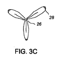
図3A〜図3Cを参照すると、バルーンを処理して、その化学的及び/又は機械的特性(剛性又は曲げ強度など)を異なる領域において異なる様式で改変することにより、望ましい突出部形状を形成しやすくなる。図3A及び図3Bを特に参照すると、バルーン12に、他方の領域及び改変されていないバルーン材料の領域と交互に配置される改変された一連の領域26、28を有する。特性が互いに異なるように、領域26、28は異なる工程にて処理されている。図3Cも参照すると、図示される実施形態においては、領域26は、バルーンが収縮すると、突出部同士の間に谷を形成し、かつ領域28が突出部の山を形成するように改変されている。
Referring to FIGS. 3A-3C, the balloon is processed to modify the chemical and / or mechanical properties (such as stiffness or flexural strength) in different regions to form the desired protrusion shape. It becomes easy. With particular reference to FIGS. 3A and 3B, the
図4A及び図4Bを参照すると、領域26、28は、バルーン材料を融除し、バルーン材料の結晶化度を変更する別個の工程により形成される。材料を融除し、材料の結晶化度を高めるために、バルーンの領域26、28は、紫外放射に暴露される。図4Aを参照すると、領域26は、レーザフルエンスが材料の融除閾値を超えるように、暴露された領域にエネルギーを提供すべくコントローラ32によって制御されるレーザ30からの紫外放射に暴露される。化学結合が切断されて、材料は破壊されてエネルギーフラグメントとなり、融除域が残る。エネルギーのほとんどは放出された材料に蓄積されていると理論化されるため、周囲の材料にはほとんど熱による損傷がない。領域26への高エネルギー入力は、材料の厚さの一部を取除くため、これらの領域の剛性を、より低い総エネルギーに暴露された領域又は改変されていないポリマーよりも低くする。その結果、バルーンが収縮させられるにつれて、より可撓性の高い領域26がより急速に折れて潰れる傾向を示し、谷を形成する。図4Bを参照すると、領域28は、より低い(融除閾値よりも低い)フルエンスにて紫外放射に暴露されることにより形成される。低エネルギーで処理された領域28の結晶化度は高められていており、これにより、これらの領域の剛性又は係数を増大させる。高められた剛性により、処理された領域は、改変されていない領域よりも可撓性が低くなり、したがって、剛性の高い領域においては、改変されていない領域よりもバルーンが折れ曲がりにくい。剛性の高い領域28は、再度折り畳まれると、突出部の山を形成する。このため、バルーンは3つの領域を備え、該3つの領域のそれぞれは、各領域における材料の厚さ量又は結晶化度が異なるため、異なる可撓性を有する
UV放射への暴露は、ポリマーの結晶化度の上昇及び/又はポリマー材料の融除又は除去を可能にする。バルーンが融除される場合、除去される材料の量は、例えばバルーンの壁厚の約0.1〜15%(0.5〜2.5%など)とすることができる。バルーンの結晶化度が実質的な融除効果を生ずることなく変更される場合、ポリマーの結晶化度は、改変されていないポリマーに比較して、約2〜90%(例えば2〜5%、5〜10%、10〜20%、20〜40%、40〜60%、60〜70%、70〜80%、80〜90%、又は20〜80%)高めることができる。ある実施形態では、結晶化度のパーセントは、改変前に比べて改変後は2倍、3倍、又は4倍になり得る。結晶化度及び/又は材料除去の量は、精細にバルーンの再折り畳み特性を調整するように選択することができる。材料が除去されるか否かは、レーザのフルエンス及びバルーンの形成材料により決定される。結晶化度の変更量は、暴露された領域に提供されるエネルギーを制御することにより(例えば暴露時間、フルエンス及び/又は放射の波長を制御することにより)、制御することができる。結晶化度は、低フルエンスにて暴露時間を増大させることにより高めることができる。好適なレーザは、波長約193nmのマルチガスUVエキシマレーザである。紫外線アブレーションは、米国特許第4,911,711号明細書においてさらに説明されている。好適な融除及び制御システムは、ドイツ連邦共和国、ゲッティンゲン(Goettingen)に所在するコヒーレント・ラムダ・フィジックス社(Coherent Lambda Physiks) から入手できる。結晶化度は、WAX/SAX−X線回折によって測定することができる。結晶化度の測定は、ミネソタ大学シェパード特性解析研究室(Shepard characterization lab)のような専門業者において行うことができる。
With reference to FIGS. 4A and 4B,
図5A及び図5Bを参照すると、別の実施形態においては、領域34、36は異なる改変技術を用いて形成することができる。領域34、36はともに結晶化度が高められているが、一方の領域34は、他方の領域36よりも高い結晶化度を有する。バルーンが潰れるときに、より高い結晶化度を有する領域34は、折り目の山を形成する。幾分高められた結晶化度を有する領域36(つまり改変されていないバルーン材料よりは高い結晶化度を有するが、最も高い結晶化度を有する領域34よりは低い結晶化度を有する領域)は、潰れた状態のバルーンの突出部の間の谷となるように折れ曲がる傾向にある。
Referring to FIGS. 5A and 5B, in another embodiment,
バルーンを2つの異なる処理方法で処理する代わりに、バルーンは、バルーンの表面から実質的に材料を除去することなく(つまり融除せずに)結晶化度を高める単一の処理方法のみで処理されてもよい。処理された領域と処理されていない領域とにおけるバルーンの厚さはほぼ同じであってもよい。結晶化度は、ガラス転移温度と溶融流動温度との間の温度にポリマー材料を熱することによって高めることができる。この温度範囲内では、結晶形成が開始されるか、又は既に存在していた結晶が大きく成長する。結晶化度は、表面でのみ変更してもよく、あるいは、バルーン壁の深さ全体にわたって変更してもよい。 Instead of treating the balloon with two different treatment methods, the balloon is treated with only a single treatment method that increases crystallinity without substantially removing (ie, not ablating) material from the surface of the balloon. May be. The thickness of the balloon in the treated area and the untreated area may be approximately the same. Crystallinity can be increased by heating the polymer material to a temperature between the glass transition temperature and the melt flow temperature. Within this temperature range, crystal formation begins or crystals that already exist grow significantly. The degree of crystallinity may be changed only on the surface or may be changed throughout the depth of the balloon wall.
UVレーザのような、バルーンへ熱を入力するために好適な技術は、主としてバルーンの表面に作用する。例えば、UVレーザは、バルーンに1〜60オングストローム(0.1〜6nm)入り込むなど、ポリマー表面に一部だけ貫入することができる。他の加熱技術は、材料により深く入り込むことができる。エネルギーを付与する一部の方法については、エネルギーは、材料に貫入するのみならず、等方的に放射する。この加熱は、材料の表面のみよりも多く加熱されるため、材料の大規模な又はバルクでの加熱であると考えられる。CO2レーザ、IRレーザ、YAGレーザ、ダイオードレーザ、もしくは他の好適な光子源のようなレーザ、加熱棒(すなわち熱カートリッジに接続された伝導性材料)、又はRF発生器を使用して、バルーンに熱を付与することができる。RF発生器の場合には、金属粒子を有するゼリーを処理すべき領域に塗布することができる。バルーンに熱を付与するためにレーザが使用される場合、熱を吸収し、かつ、バルーンの他の部分が同時に処理されることを防ぐために、バルーンを流体で充填することができる。なお、結晶化度の量は、例えばエネルギーがバルーンに入力される時間を調整したり、エネルギー入力装置によって出力されるエネルギーを制御したりすることにより、調整することができる。バルーンの特定の領域に熱を集中させるために、マスキングしてもよく、あるいは熱を付与する装置を結晶化が望まれる領域にのみに集中させてもよい。バルーンを処理する一部の方法では、結晶化の深さが、処理された領域が折り目の山となるか谷となるかを決定することができる。UVレーザによる表面処理は、バルーンの折り目の谷となる処理された領域を形成する傾向にあり、CO2レーザ又は加熱棒による処理は、バルーンの折り目の山となる処理された領域を形成する。 Suitable techniques for inputting heat to the balloon, such as UV lasers, operate primarily on the surface of the balloon. For example, the UV laser can penetrate only a portion of the polymer surface, such as entering the balloon 1-60 angstroms (0.1-6 nm). Other heating techniques can penetrate deeper into the material. For some methods of applying energy, energy not only penetrates the material, but isotropically radiates. Since this heating is heated more than just the surface of the material, it is considered to be a large-scale or bulk heating of the material. Using a laser such as a CO 2 laser, IR laser, YAG laser, diode laser, or other suitable photon source, a heating rod (ie, a conductive material connected to a thermal cartridge), or an RF generator, the balloon Heat can be applied to the. In the case of an RF generator, a jelly with metal particles can be applied to the area to be treated. When a laser is used to apply heat to the balloon, the balloon can be filled with fluid to absorb the heat and prevent other parts of the balloon from being processed simultaneously. Note that the amount of crystallinity can be adjusted, for example, by adjusting the time during which energy is input to the balloon or by controlling the energy output by the energy input device. Masking may be used to concentrate heat on a specific area of the balloon, or the apparatus for applying heat may be concentrated only on areas where crystallization is desired. In some methods of processing balloons, the crystallization depth can determine whether the processed region is a crease crest or a trough. Surface treatment by UV laser has a tendency to form a treated area becomes a valley of the folds of the balloon, treatment with CO 2 laser or heating rod forms a treated area becomes fold mountain balloon.
可撓性又は剛性の変化は、イオンビーム暴露やバルーン壁の領域の機械的な切断などのような他の技術によっても形成することができる。これらの技術すべては、バルーンに望ましい特性を付与するために、任意に組み合わせて使用することができる。イオンビーム処理については、2006年9月20日に出願された米国特許出願第11/533,588号明細書及び2006年2月16日に出願された米国特許出願第11/355,392号明細書に記載されている。処理された領域は、直接バルーンに対して、又は後に(例えば自由膨張又はブロー成形により)バルーンに形成される又は吹き込みされるポリマー管状パリソンに対してエネルギーを付与することによって、形成することができる。バルーンの形成は、米国特許第4,963,313号明細書でさらに説明されている。 The change in flexibility or stiffness can also be formed by other techniques such as ion beam exposure or mechanical cutting of the balloon wall region. All of these techniques can be used in any combination to give the balloon the desired properties. Regarding ion beam processing, US Patent Application No. 11 / 533,588 filed on September 20, 2006 and US Patent Application No. 11 / 355,392 filed on February 16, 2006. It is described in the book. The treated region can be formed by applying energy directly to the balloon or to a polymer tubular parison that is subsequently formed or blown into the balloon (eg, by free inflation or blow molding). . Balloon formation is further described in US Pat. No. 4,963,313.
バルーンの形成に適したポリマーとしては、二軸配向ポリマー、熱可塑性エラストマー、エンジニアリング熱可塑性エラストマー、ポリエチレン、ポリエチレンテレフタラート(PET)、ポリブチレン、ポリアミド(例えばナイロン66)、ポリエーテルブロックアミド(例えば、PEBAX(登録商標))、ポリプロピレン(PP)、ポリスチレン(PS)、ポリ塩化ビニル(PVC)、ポリテトラフルオロエチレン(PTFE)、ポリメチルメタクリラート(PMMA)、ポリイミド、ポリカーボネート(PC)、ポリイソプレンゴム(PI)、ニトリルゴム、シリコーンゴム、エチレン−プロピレンジエンゴム(EPDM)、ブチルゴム(BR)、熱可塑性ポリウレタン(PU)(例えば、PELLETHANE(登録商標)のような、グリコールエーテルとイソシアネートを含むもの)が挙げられる。特定の実施形態では、下記一般式を有するポリ(エーテル−アミド)ブロックコポリマーが用いられる。 Suitable polymers for forming the balloon include biaxially oriented polymers, thermoplastic elastomers, engineering thermoplastic elastomers, polyethylene, polyethylene terephthalate (PET), polybutylene, polyamides (eg nylon 66), polyether block amides (eg PEBAX) (Registered trademark)), polypropylene (PP), polystyrene (PS), polyvinyl chloride (PVC), polytetrafluoroethylene (PTFE), polymethyl methacrylate (PMMA), polyimide, polycarbonate (PC), polyisoprene rubber ( PI), nitrile rubber, silicone rubber, ethylene-propylene diene rubber (EPDM), butyl rubber (BR), thermoplastic polyurethane (PU) (for example, PELLETHANE®) , Those containing glycol ether and an isocyanate) and the like. In certain embodiments, a poly (ether-amide) block copolymer having the general formula:

上述したように、フルエンス閾値は、バルーン材料と材料に入力されるエネルギーの波長のタイプによって決まる。バルーンの処理に適したUVレーザは、約150〜450nm(例えば157nm、193nm、248nm、308nm、351nm)の波長を有する。PET又はPEBAX(登録商標)バルーンを193nmレーザで処理する場合、約150mJ/cm2未満(例えば約60〜70mJ/cm2)とすれば、バルーン材料の融除が回避される。材料及びレーザの他の組合せは、融除を回避するために異なるフルエンス閾値を有するであろう。 As described above, the fluence threshold depends on the balloon material and the type of wavelength of energy input to the material. UV lasers suitable for balloon processing have a wavelength of about 150-450 nm (eg, 157 nm, 193 nm, 248 nm, 308 nm, 351 nm). When treating a PET or PEBAX® balloon with a 193 nm laser, ablation of the balloon material is avoided if it is less than about 150 mJ / cm 2 (eg, about 60-70 mJ / cm 2 ). Other combinations of materials and lasers will have different fluence thresholds to avoid ablation.
説明されている直線状の処理された領域に加えて、処理された領域は、再折り畳み性を向上させるために、他の形状となるように構成されてもよい。一部の実施形態では、処理された領域は、バルーンの周りにおいて螺旋状をなす。一部の実施形態では、処理された領域は、バルーンの円錐部の周りのみ、バルーンの本体のみ、又はバルーンの本体及び円錐部の両方に配置される。別の実施形態では、処理された領域は、連続的な線状に形成されず、収縮時にバルーンが折り畳まれる場所を決定する一連の点、短線又は形状として形成される。 In addition to the linear processed areas described, the processed areas may be configured to have other shapes to improve refoldability. In some embodiments, the treated area spirals around the balloon. In some embodiments, the treated region is disposed only around the cone of the balloon, only the body of the balloon, or both the body and cone of the balloon. In another embodiment, the treated region is not formed as a continuous line, but as a series of dots, short lines or shapes that determine where the balloon is folded when deflated.
バルーンは、2つ以上の、好ましくは3つ、4つ又はそれ以上の個数の突出部の形成を容易にするために処理することができる。バルーンが管腔での使用後に収縮させられたときに形成される突出部は、送達のために形成され、巻き付けられた突出部の位置に対応する位置に形成されてもよく、あるいは、突出部は、収縮時には異なる位置に形成されてもよい。バルーンが複数の突出部を有する輪郭へと潰れることができる場合、バルーンが扁平化され又はパンケーキ状にされるときよりも、潰れたバルーンの径が小さくなる。このより小さな輪郭は、ステント又は血管のような管腔から潰れたバルーンを除去しやすくすることができる。すなわち、除去時に管腔に張り付いたり引っ掛かったりするおそれを低減して、折り畳まれたバルーンを管腔からスムーズに除去することができる。バルーンの表面には、処理された領域のうち任意の数の領域、例えば4つ、5つ、6つ、7つ、又は8つの処理された領域を形成することができる。バルーンは、冠状血管、末梢血管、頸動脈、食道又は尿道での適用を含む、血管及び非血管での適用に使用することができる。 The balloon can be treated to facilitate the formation of two or more, preferably three, four or more protrusions. The protrusion formed when the balloon is deflated after use in the lumen may be formed for delivery and at a position corresponding to the position of the wrapped protrusion, or the protrusion May be formed at different positions during contraction. If the balloon can be collapsed into a profile with multiple protrusions, the collapsed balloon will have a smaller diameter than when the balloon is flattened or pancake-shaped. This smaller profile can facilitate removal of collapsed balloons from lumens such as stents or blood vessels. That is, the risk of sticking to or catching on the lumen during removal is reduced, and the folded balloon can be smoothly removed from the lumen. Any number of treated areas can be formed on the surface of the balloon, eg, 4, 5, 6, 7, or 8 treated areas. Balloons can be used for vascular and non-vascular applications, including coronary, peripheral, carotid, esophageal or urethral applications.
[例]
3.0×16mmのTAXUS(登録商標)Liberte(商標)OTW(PEBAX(登録商標)7233)ポリマーバルーン(米国マサチューセッツ州ナティックNatick)に所在するボストン・サイエンティフィック社(Boston Scitentific)より販売される)が、2psi(約13.9kPa)の圧力まで膨張させられて、パルス作用時間29ns、波長193nmにて作動し、30mJ/cm2(PEBAX(登録商標)の融除閾値である約60〜70mJ/cm2よりも低い)のフルエンスを提供するために減衰器が30VAに設定された、ラムダ201iマルチガスエキシマレーザ(ドイツ連邦共和国ゲッティンゲンに所在するコヒーレント・ラムダ・フィジックス社より販売される)を用いて紫外放射に暴露する。レーザからのビームは、約1mm幅及び約5mm長である。バルーンの周りに等距離だけ離間する幅約1mmの3つの直線状領域が暴露される。領域は、400ミクロン(400μm)のショット間隔で暴露される。暴露された領域は不透明になり、結晶化度が約22%であるのに対し、未処理の領域は結晶化度が約16%である。
[Example]
3.0 x 16 mm TAXUS (R) Liberte (TM) OTW (PEBAX (R) 7233) Polymer Balloon (Boston Scitentific, Natick, Massachusetts, USA) ) Is expanded to a pressure of 2 psi (about 13.9 kPa), operates at a pulse action time of 29 ns, a wavelength of 193 nm, and ablation threshold of 30 mJ / cm 2 (about 60-70 mJ of PEBAX®) Using a lambda 201i multi-gas excimer laser (sold by Coherent Lambda Physics, Göttingen, Germany) with an attenuator set at 30 VA to provide a fluence of </ cm 2 Exposure to ultraviolet radiation. The beam from the laser is about 1 mm wide and about 5 mm long. Three linear regions of about 1 mm width that are spaced equidistant around the balloon are exposed. The area is exposed with a shot spacing of 400 microns (400 μm). The exposed areas become opaque and have a crystallinity of about 22%, while the untreated areas have a crystallinity of about 16%.
図6を参照すると、UVレーザの適用のような一部の熱付与の効果は、バルーンの表面で材料を再配列することである。UVレーザを使用して結晶化したバルーン表面の拡大図はノジュール52を示す。バルーンはTAXUS(登録商標)Liberte(商標)OTW(PEBAX(登録商標)7233)ポリマーバルーン(米国マサチューセッツ州ナティックに所在するボストン・サイエンティフィック社より販売される)であり、波長193nmにて作動し、30mJ/cm2の出力を達成するために減衰器が30VAに設定された、ラムダ201iマルチガスエキシマレーザ(ドイツ連邦共和国ゲッティンゲンに所在するコヒーレント・ラムダ・フィジックス社より販売される)を用いてUV放射に暴露した。ノジュール52の形成は、バルーン壁からポリマー材料を除去しないが、バルーン表面の材料を再配列し、ノジュール間の有効壁厚を減じることができる。処理されていないバルーン壁は外観が平滑であり、ノジュールが存在しない。ノジュール52は、バルーンがUVレーザによって処理されると観察されるが、CO2レーザ又は加熱棒のような他の処理では観察されない。UVレーザによって処理される領域はまた、表面の改変により不透明になる。
Referring to FIG. 6, the effect of some heat application, such as application of a UV laser, is to rearrange the material at the surface of the balloon. An enlarged view of the balloon surface crystallized using a UV laser shows
図7Aを参照すると、処理されたバルーンは、UVレーザを用いて形成された3つの縞部62を備える。すべての縞部は、バルーンの本体−円錐部移行領域を越えて、先端上及び基端上を延びる。各縞部は1mmの幅を有する。図7Bを参照すると、端面図は、バルーンの円錐部の3つの処理された領域を示す。図8A及び図8Bを参照すると、折り畳まれたバルーンは3つの突出部を形成する。3つに折り畳まれたバルーンの輪郭は、パンケーキ状のバルーン、すなわち処理されておらず、収縮時に折り畳まれず扁平なバルーンに比較して、約30%小さい。3.0×16mmTAXUS(登録商標)Liberte(商標)OTWバルーンは、再折り畳み性を向上させるために領域において処理され、折り畳まれたときの輪郭が2.85mmであった。処理されていないパンケーキ状の同様のバルーンの輪郭は4.16mmである。
Referring to FIG. 7A, the treated balloon comprises three
本願で参照されるすべての特許、特許出願及び刊行物はすべて、参照によりその全体が本明細書の一部を構成する。
さらなる実施形態は以下の請求項に記載される。
All patents, patent applications and publications referred to in this application are hereby incorporated by reference in their entirety.
Further embodiments are set forth in the following claims.
Claims (28)
ポリマーで形成される管状の膨張可能なバルーン又はバルーンパリソンを提供する工程と、
可撓性を高めるためにポリマーを除去して一連の第1領域を形成する工程と、
第1領域よりも可撓性が低くなるように、紫外放射への暴露、加熱又はイオン注入により処理された一連の第2領域を形成する工程と
を含み、バルーンを収縮させると、第2領域の位置にて突出部の山を形成するべくバルーンが折り畳まれるように、前記処理された第1及び第2領域が前記バルーンの周りにおいて交互に放射状に配置されるか、前記処理された第1及び第2領域が、前記バルーンの周りにおいて処理されていない領域と交互に放射状に配置される、方法。 A method for producing an inflatable medical balloon comprising:
Providing a tubular inflatable balloon or balloon parison formed of a polymer;
Removing the polymer to increase flexibility to form a series of first regions;
Forming a series of second regions treated by exposure to ultraviolet radiation, heating, or ion implantation so as to be less flexible than the first region, and when the balloon is deflated, the second region The processed first and second regions are alternately arranged radially around the balloon or the processed first so that the balloon is folded to form a ridge of protrusions at the position And a second region is arranged radially with alternating unprocessed regions around the balloon.
ポリマーで形成される管状の膨張可能なバルーン又はバルーンパリソンを提供する工程と、
バルーンからポリマーを除去することなくポリマー結晶化度が高められた、処理された一連の第1領域を形成する工程と
前記処理された第1領域とは異なる結晶化度を有する処理された一連の第2領域を形成する工程と
を含み、バルーンが収縮させられると、該処理された一連の第1領域の位置にて突出部の山または谷を形成するべくバルーンが折り畳まれるように、前記処理された第1及び第2領域が前記バルーンの周りにおいて交互に放射状に配置されるか、前記処理された第1及び第2領域が、前記バルーンの周りにおいて処理されていない領域と交互に放射状に配置される、方法。 A method for producing an inflatable medical balloon comprising:
Providing a tubular inflatable balloon or balloon parison formed of a polymer;
Forming a treated series of first regions with increased polymer crystallinity without removing the polymer from the balloon; and the treated series having a different degree of crystallinity than the treated first regions. Forming a second region, wherein when the balloon is deflated, the treatment is performed such that the balloon is folded to form a ridge or valley of protrusions at the location of the treated first region. The first and second regions formed are alternately arranged radially around the balloon, or the processed first and second regions are alternately arranged radially with the non-processed region around the balloon. Arranged the way.
ポリマーで形成される円筒形のバルーン壁を備え、該壁は処理された第1の領域を備え、該第1領域では、ポリマーの結晶化度が、ポリマーで形成される一連の第2領域の結晶化度よりも高く、前記処理された第1領域は前記第2領域とは異なる可撓性を有し、前記バルーン器具は、収縮すると、前記処理された第1領域の位置にて突出部の谷を形成するべく折り畳まれるように、前記処理された第1領域、及び前記第2領域が前記バルーンの周りにおいて交互に放射状に配置されるか、前記処理された第1領域、及び前記第2領域が、前記バルーンの周りにおいて処理されていない領域と交互に放射状に配置される、医療用バルーン器具。 An inflatable medical balloon device,
A cylindrical balloon wall formed of a polymer, the wall comprising a treated first region, wherein the crystallinity of the polymer is a series of second regions formed of the polymer. The treated first region has a different flexibility than the second region and has a higher degree of crystallinity than the second region, and when the balloon device is deflated, it protrudes at the position of the treated first region. valley to be folded to form the said processed first area, and if the second region is disposed radially alternately around said balloon, said processed first regions, and the first A medical balloon device, wherein the two regions are arranged radially with alternating untreated regions around the balloon.
前記バルーンが突出部を有するように配置し、該突出部を巻き付ける工程と
を含み、前記バルーンに少なくとも3つの突出部が形成される、医療器具の製造方法。 Providing a medical device according to claim 25;
A method of manufacturing a medical device, comprising: arranging the balloon so as to have a protrusion and winding the protrusion, wherein at least three protrusions are formed on the balloon.
Applications Claiming Priority (3)
| Application Number | Priority Date | Filing Date | Title |
|---|---|---|---|
| US11/599,049 | 2006-11-14 | ||
| US11/599,049 US8845581B2 (en) | 2006-11-14 | 2006-11-14 | Medical balloon deflation |
| PCT/US2007/078671 WO2008060750A2 (en) | 2006-11-14 | 2007-09-17 | Medical balloon deflation |
Publications (3)
| Publication Number | Publication Date |
|---|---|
| JP2010509028A JP2010509028A (en) | 2010-03-25 |
| JP2010509028A5 JP2010509028A5 (en) | 2011-02-24 |
| JP5466008B2 true JP5466008B2 (en) | 2014-04-09 |
Family
ID=39345319
Family Applications (1)
| Application Number | Title | Priority Date | Filing Date |
|---|---|---|---|
| JP2009537249A Active JP5466008B2 (en) | 2006-11-14 | 2007-09-17 | Medical balloon contraction |
Country Status (6)
| Country | Link |
|---|---|
| US (1) | US8845581B2 (en) |
| EP (1) | EP2089087B1 (en) |
| JP (1) | JP5466008B2 (en) |
| AT (1) | ATE551093T1 (en) |
| CA (1) | CA2669605C (en) |
| WO (1) | WO2008060750A2 (en) |
Families Citing this family (19)
| Publication number | Priority date | Publication date | Assignee | Title |
|---|---|---|---|---|
| US8153181B2 (en) | 2006-11-14 | 2012-04-10 | Boston Scientific Scimed, Inc. | Medical devices and related methods |
| EP2072067A1 (en) * | 2007-12-21 | 2009-06-24 | Abbott Laboratories Vascular Enterprises Limited | Lamellar shaped layers in medical devices |
| DE102008008926A1 (en) * | 2008-02-13 | 2009-08-20 | Biotronik Vi Patent Ag | System for introducing an intraluminal endoprosthesis and method of making such a system |
| DE102008008925A1 (en) * | 2008-02-13 | 2009-08-20 | Biotronik Vi Patent Ag | Catheter, intraluminal endoprosthesis delivery system, and method of making the same |
| EP2300093B1 (en) * | 2008-06-05 | 2016-04-20 | Boston Scientific Scimed, Inc. | Deflatable bifurcated device |
| EP2299945B1 (en) | 2008-06-05 | 2016-03-23 | Boston Scientific Scimed, Inc. | Balloon bifurcated lumen treatment |
| EP2370138B1 (en) * | 2008-11-25 | 2020-12-30 | Edwards Lifesciences Corporation | Apparatus for in situ expansion of prosthetic device |
| US8864786B2 (en) * | 2009-04-09 | 2014-10-21 | Medtronic Vascular, Inc. | Dual-layer medical balloon and process of making |
| CA2773465A1 (en) * | 2009-09-30 | 2011-04-07 | Sanofi-Aventis Deutschland Gmbh | Method for treating a plastic part, method for manufacturing a drug delivery device and drug delivery device |
| US9364637B2 (en) * | 2011-09-06 | 2016-06-14 | Medtronic, Inc. | Transcatheter balloon-assisted mitral valve navigation device and method |
| WO2013134437A1 (en) * | 2012-03-06 | 2013-09-12 | Futurematrix Interventional, Inc. | Medical balloon with enhanced refolding properties |
| JP6184070B2 (en) * | 2012-09-19 | 2017-08-23 | 株式会社カネカ | Method for manufacturing balloon for balloon catheter |
| JP6259560B2 (en) * | 2012-09-19 | 2018-01-10 | 株式会社カネカ | Balloon for balloon catheter |
| EP2914328A1 (en) * | 2012-11-02 | 2015-09-09 | Vessix Vascular, Inc. | Flex circuit/balloon assemblies utilizing textured surfaces for enhanced bonding |
| US20140213970A1 (en) * | 2013-01-28 | 2014-07-31 | Edwards Lifesciences Corporation | Catheter balloon and method of fabrication |
| WO2015195752A1 (en) * | 2014-06-17 | 2015-12-23 | Covidien Lp | Medical balloon including pleats |
| US9828456B2 (en) | 2016-04-11 | 2017-11-28 | International Business Machines Corporation | Macromolecular block copolymers |
| US9834637B2 (en) | 2016-04-11 | 2017-12-05 | International Business Machines Corporation | Macromolecular block copolymer formation |
| US10414913B2 (en) | 2016-04-11 | 2019-09-17 | International Business Machines Corporation | Articles of manufacture including macromolecular block copolymers |
Family Cites Families (34)
| Publication number | Priority date | Publication date | Assignee | Title |
|---|---|---|---|---|
| US4941877A (en) | 1989-01-26 | 1990-07-17 | Cordis Corporation | Balloon catheter |
| US5267959A (en) * | 1991-11-29 | 1993-12-07 | Schneider, Inc. | Laser bonding of angioplasty balloon catheters |
| US5352199A (en) * | 1993-05-28 | 1994-10-04 | Numed, Inc. | Balloon catheter |
| US5746745A (en) * | 1993-08-23 | 1998-05-05 | Boston Scientific Corporation | Balloon catheter |
| US5545132A (en) | 1993-12-21 | 1996-08-13 | C. R. Bard, Inc. | Helically grooved balloon for dilatation catheter and method of using |
| NL1000106C2 (en) | 1995-04-10 | 1996-10-11 | Cordis Europ | Balloon balloon balloon catheter and method of making the balloon. |
| US5733301A (en) | 1996-01-11 | 1998-03-31 | Schneider (Usa) Inc. | Laser ablation of angioplasty catheters and balloons |
| US5853389A (en) | 1996-03-07 | 1998-12-29 | Cordis Corporation | Balloon catheter and method for manufacturing |
| US5810867A (en) * | 1997-04-28 | 1998-09-22 | Medtronic, Inc. | Dilatation catheter with varied stiffness |
| US6030369A (en) * | 1997-07-03 | 2000-02-29 | Target Therapeutics Inc. | Micro catheter shaft |
| US6242063B1 (en) * | 1997-09-10 | 2001-06-05 | Scimed Life Systems, Inc. | Balloons made from liquid crystal polymer blends |
| US6296655B1 (en) * | 1998-04-27 | 2001-10-02 | Advanced Cardiovascular Systems, Inc. | Catheter balloon with biased multiple wings |
| US6193738B1 (en) * | 1998-05-11 | 2001-02-27 | Scimed Life Systems, Inc. | Balloon cones and waists thinning methodology |
| CN100406079C (en) | 1998-10-05 | 2008-07-30 | 钟渊化学工业株式会社 | Balloon catheter and production method therefor |
| US6592550B1 (en) * | 1999-09-17 | 2003-07-15 | Cook Incorporated | Medical device including improved expandable balloon |
| US6702802B1 (en) * | 1999-11-10 | 2004-03-09 | Endovascular Technologies, Inc. | Catheters with improved transition |
| US6544224B1 (en) * | 2000-05-05 | 2003-04-08 | Advanced Cardiovascular Systems, Inc. | Lobed balloon catheter and method of use |
| JP4538918B2 (en) * | 2000-08-02 | 2010-09-08 | 株式会社カネカ | Medical catheter for treating part of a body tube with ionizing radiation |
| US6585926B1 (en) | 2000-08-31 | 2003-07-01 | Advanced Cardiovascular Systems, Inc. | Method of manufacturing a porous balloon |
| US7004963B2 (en) * | 2001-09-14 | 2006-02-28 | Scimed Life Systems, Inc. | Conformable balloons |
| US20030144683A1 (en) | 2001-12-13 | 2003-07-31 | Avantec Vascular Corporation | Inflatable members having concentrated force regions |
| US7985234B2 (en) | 2002-02-27 | 2011-07-26 | Boston Scientific Scimed, Inc. | Medical device |
| US6989025B2 (en) | 2002-10-04 | 2006-01-24 | Boston Scientific Scimed, Inc. | Extruded tubing with discontinuous striping |
| US7306616B2 (en) | 2003-05-05 | 2007-12-11 | Boston Scientific Scimed, Inc. | Balloon catheter and method of making same |
| US8025637B2 (en) | 2003-07-18 | 2011-09-27 | Boston Scientific Scimed, Inc. | Medical balloons and processes for preparing same |
| US7604621B2 (en) | 2003-07-30 | 2009-10-20 | Boston Scientific Scimed, Inc. | Bifurcated stent delivery system |
| US7264458B2 (en) | 2004-01-07 | 2007-09-04 | Boston Scientific Scimed, Inc. | Process and apparatus for forming medical device balloons |
| US20050177130A1 (en) | 2004-02-10 | 2005-08-11 | Angioscore, Inc. | Balloon catheter with spiral folds |
| US7713233B2 (en) * | 2004-04-12 | 2010-05-11 | Boston Scientific Scimed, Inc. | Balloons having a crosslinkable layer |
| US8550985B2 (en) | 2004-12-14 | 2013-10-08 | Boston Scientific Scimed, Inc. | Applications of LIPSS in polymer medical devices |
| US8202245B2 (en) | 2005-01-26 | 2012-06-19 | Boston Scientific Scimed, Inc. | Medical devices and methods of making the same |
| US20060182873A1 (en) | 2005-02-17 | 2006-08-17 | Klisch Leo M | Medical devices |
| US20070244501A1 (en) * | 2006-04-18 | 2007-10-18 | Horn Daniel J | Medical balloons |
| US7963942B2 (en) * | 2006-09-20 | 2011-06-21 | Boston Scientific Scimed, Inc. | Medical balloons with modified surfaces |
-
2006
- 2006-11-14 US US11/599,049 patent/US8845581B2/en active Active
-
2007
- 2007-09-17 CA CA2669605A patent/CA2669605C/en not_active Expired - Fee Related
- 2007-09-17 JP JP2009537249A patent/JP5466008B2/en active Active
- 2007-09-17 EP EP07842621A patent/EP2089087B1/en not_active Not-in-force
- 2007-09-17 WO PCT/US2007/078671 patent/WO2008060750A2/en active Application Filing
- 2007-09-17 AT AT07842621T patent/ATE551093T1/en active
Also Published As
| Publication number | Publication date |
|---|---|
| JP2010509028A (en) | 2010-03-25 |
| EP2089087B1 (en) | 2012-03-28 |
| US20080114294A1 (en) | 2008-05-15 |
| ATE551093T1 (en) | 2012-04-15 |
| US8845581B2 (en) | 2014-09-30 |
| CA2669605C (en) | 2015-02-24 |
| WO2008060750A3 (en) | 2008-10-16 |
| WO2008060750A2 (en) | 2008-05-22 |
| EP2089087A2 (en) | 2009-08-19 |
| CA2669605A1 (en) | 2008-05-22 |
Similar Documents
| Publication | Publication Date | Title |
|---|---|---|
| JP5466008B2 (en) | Medical balloon contraction | |
| EP1848487B1 (en) | Medical devices | |
| EP2763735B1 (en) | Balloon assemblies having controllably variable topographies | |
| US8034280B2 (en) | Balloon catheters and methods for manufacturing balloons for balloon catheters | |
| US6165152A (en) | Catheter with a flexible tip and taper and method of manufacture | |
| US20070299392A1 (en) | Material Delivery System | |
| US7691082B2 (en) | Medical devices | |
| US5624433A (en) | Angioplasty balloon with light incisor | |
| JPH04501670A (en) | Intraluminal sealing with biodegradable polymeric materials | |
| JP2008509749A (en) | Method and apparatus for manipulating a vascular prosthesis | |
| JP2008528199A (en) | Medical device and manufacturing method thereof | |
| US8827954B2 (en) | Deflatable bifurcated device | |
| WO2018060466A1 (en) | Finned angioplasty balloon | |
| JP2014057793A (en) | Balloon for balloon catheter | |
| JP6184070B2 (en) | Method for manufacturing balloon for balloon catheter | |
| WO2016081279A1 (en) | Inflatable device with etched modifications |
Legal Events
| Date | Code | Title | Description |
|---|---|---|---|
| A621 | Written request for application examination |
Free format text: JAPANESE INTERMEDIATE CODE: A621 Effective date: 20100916 |
|
| A521 | Request for written amendment filed |
Free format text: JAPANESE INTERMEDIATE CODE: A523 Effective date: 20110105 |
|
| RD04 | Notification of resignation of power of attorney |
Free format text: JAPANESE INTERMEDIATE CODE: A7424 Effective date: 20120229 |
|
| A131 | Notification of reasons for refusal |
Free format text: JAPANESE INTERMEDIATE CODE: A131 Effective date: 20120612 |
|
| A601 | Written request for extension of time |
Free format text: JAPANESE INTERMEDIATE CODE: A601 Effective date: 20120912 |
|
| A602 | Written permission of extension of time |
Free format text: JAPANESE INTERMEDIATE CODE: A602 Effective date: 20120920 |
|
| A521 | Request for written amendment filed |
Free format text: JAPANESE INTERMEDIATE CODE: A523 Effective date: 20120928 |
|
| A131 | Notification of reasons for refusal |
Free format text: JAPANESE INTERMEDIATE CODE: A131 Effective date: 20130326 |
|
| A521 | Request for written amendment filed |
Free format text: JAPANESE INTERMEDIATE CODE: A523 Effective date: 20130626 |
|
| TRDD | Decision of grant or rejection written | ||
| A01 | Written decision to grant a patent or to grant a registration (utility model) |
Free format text: JAPANESE INTERMEDIATE CODE: A01 Effective date: 20140107 |
|
| A61 | First payment of annual fees (during grant procedure) |
Free format text: JAPANESE INTERMEDIATE CODE: A61 Effective date: 20140123 |
|
| R150 | Certificate of patent or registration of utility model |
Ref document number: 5466008 Country of ref document: JP Free format text: JAPANESE INTERMEDIATE CODE: R150 Free format text: JAPANESE INTERMEDIATE CODE: R150 |
|
| R250 | Receipt of annual fees |
Free format text: JAPANESE INTERMEDIATE CODE: R250 |
|
| R250 | Receipt of annual fees |
Free format text: JAPANESE INTERMEDIATE CODE: R250 |
|
| R250 | Receipt of annual fees |
Free format text: JAPANESE INTERMEDIATE CODE: R250 |
|
| R250 | Receipt of annual fees |
Free format text: JAPANESE INTERMEDIATE CODE: R250 |
|
| R250 | Receipt of annual fees |
Free format text: JAPANESE INTERMEDIATE CODE: R250 |
|
| R250 | Receipt of annual fees |
Free format text: JAPANESE INTERMEDIATE CODE: R250 |
|
| R250 | Receipt of annual fees |
Free format text: JAPANESE INTERMEDIATE CODE: R250 |
|
| R250 | Receipt of annual fees |
Free format text: JAPANESE INTERMEDIATE CODE: R250 |
|
| S111 | Request for change of ownership or part of ownership |
Free format text: JAPANESE INTERMEDIATE CODE: R313113 |
|
| S531 | Written request for registration of change of domicile |
Free format text: JAPANESE INTERMEDIATE CODE: R313531 |
|
| R371 | Transfer withdrawn |
Free format text: JAPANESE INTERMEDIATE CODE: R371 |
|
| S111 | Request for change of ownership or part of ownership |
Free format text: JAPANESE INTERMEDIATE CODE: R313113 |
|
| S531 | Written request for registration of change of domicile |
Free format text: JAPANESE INTERMEDIATE CODE: R313531 |