JP5465386B2 - Wrap film device with flap - Google Patents
Wrap film device with flap Download PDFInfo
- Publication number
- JP5465386B2 JP5465386B2 JP2008022525A JP2008022525A JP5465386B2 JP 5465386 B2 JP5465386 B2 JP 5465386B2 JP 2008022525 A JP2008022525 A JP 2008022525A JP 2008022525 A JP2008022525 A JP 2008022525A JP 5465386 B2 JP5465386 B2 JP 5465386B2
- Authority
- JP
- Japan
- Prior art keywords
- flap
- front wall
- wrap film
- box
- wall
- Prior art date
- Legal status (The legal status is an assumption and is not a legal conclusion. Google has not performed a legal analysis and makes no representation as to the accuracy of the status listed.)
- Active
Links
- 238000007789 sealing Methods 0.000 claims description 27
- 239000000853 adhesive Substances 0.000 claims description 11
- 230000001070 adhesive effect Effects 0.000 claims description 11
- 101150037531 sinR gene Proteins 0.000 claims description 10
- 239000012790 adhesive layer Substances 0.000 claims description 8
- 230000000694 effects Effects 0.000 description 2
- 229920006280 packaging film Polymers 0.000 description 2
- 239000012785 packaging film Substances 0.000 description 2
- 238000004806 packaging method and process Methods 0.000 description 2
- 239000004820 Pressure-sensitive adhesive Substances 0.000 description 1
- 230000003247 decreasing effect Effects 0.000 description 1
- 238000005516 engineering process Methods 0.000 description 1
- 230000002349 favourable effect Effects 0.000 description 1
- 230000014509 gene expression Effects 0.000 description 1
- 239000010410 layer Substances 0.000 description 1
- 230000004048 modification Effects 0.000 description 1
- 238000012986 modification Methods 0.000 description 1
- 239000002966 varnish Substances 0.000 description 1
Images


Classifications
-
- B—PERFORMING OPERATIONS; TRANSPORTING
- B65—CONVEYING; PACKING; STORING; HANDLING THIN OR FILAMENTARY MATERIAL
- B65D—CONTAINERS FOR STORAGE OR TRANSPORT OF ARTICLES OR MATERIALS, e.g. BAGS, BARRELS, BOTTLES, BOXES, CANS, CARTONS, CRATES, DRUMS, JARS, TANKS, HOPPERS, FORWARDING CONTAINERS; ACCESSORIES, CLOSURES, OR FITTINGS THEREFOR; PACKAGING ELEMENTS; PACKAGES
- B65D25/00—Details of other kinds or types of rigid or semi-rigid containers
- B65D25/38—Devices for discharging contents
- B65D25/52—Devices for discharging successive articles or portions of contents
-
- B—PERFORMING OPERATIONS; TRANSPORTING
- B65—CONVEYING; PACKING; STORING; HANDLING THIN OR FILAMENTARY MATERIAL
- B65D—CONTAINERS FOR STORAGE OR TRANSPORT OF ARTICLES OR MATERIALS, e.g. BAGS, BARRELS, BOTTLES, BOXES, CANS, CARTONS, CRATES, DRUMS, JARS, TANKS, HOPPERS, FORWARDING CONTAINERS; ACCESSORIES, CLOSURES, OR FITTINGS THEREFOR; PACKAGING ELEMENTS; PACKAGES
- B65D5/00—Rigid or semi-rigid containers of polygonal cross-section, e.g. boxes, cartons or trays, formed by folding or erecting one or more blanks made of paper
- B65D5/42—Details of containers or of foldable or erectable container blanks
- B65D5/72—Contents-dispensing means
-
- B—PERFORMING OPERATIONS; TRANSPORTING
- B65—CONVEYING; PACKING; STORING; HANDLING THIN OR FILAMENTARY MATERIAL
- B65H—HANDLING THIN OR FILAMENTARY MATERIAL, e.g. SHEETS, WEBS, CABLES
- B65H2701/00—Handled material; Storage means
- B65H2701/10—Handled articles or webs
- B65H2701/17—Nature of material
- B65H2701/175—Plastic
- B65H2701/1752—Polymer film
-
- B—PERFORMING OPERATIONS; TRANSPORTING
- B65—CONVEYING; PACKING; STORING; HANDLING THIN OR FILAMENTARY MATERIAL
- B65H—HANDLING THIN OR FILAMENTARY MATERIAL, e.g. SHEETS, WEBS, CABLES
- B65H35/00—Delivering articles from cutting or line-perforating machines; Article or web delivery apparatus incorporating cutting or line-perforating devices, e.g. adhesive tape dispensers
- B65H35/0006—Article or web delivery apparatus incorporating cutting or line-perforating devices
Landscapes
- Engineering & Computer Science (AREA)
- Mechanical Engineering (AREA)
- Cartons (AREA)
- Details Of Rigid Or Semi-Rigid Containers (AREA)
Description
本発明は、食品その他の包装に使用されるラップフィルムのロールを容器内に収容し、容器外へラップフィルムを容易に引出し可能としたラップフィルム装置に関する。より詳しくは、本発明は、容器から引き出されたラップフィルムに切断刃が触れラップフィルムを損傷する「刃当たり」と呼ぶ現象が生じないようにしたラップフィルム装置を提供する。本発明は、左利きの人及び右ききの人の両者に使用上の不便を生じない改良されたラップフィルム装置を提供する。また、本発明は、ラップフィルム及びその端縁(切断縁)を容器壁面から離間させ、ラップフィルムの端縁を指で摘みラップフィルムを容器外へ引き出すことを可能にするためのフラップを備えるラップフィルム装置に関する。更に本発明は、引出されたラップフィルムの端縁がロール上に引き戻されることを防止したラップフィルム装置を提供する。 The present invention relates to a wrap film apparatus in which a roll of a wrap film used for packaging of food and other products is accommodated in a container, and the wrap film can be easily pulled out of the container. More specifically, the present invention provides a wrap film apparatus in which a phenomenon called “per edge”, in which a cutting blade touches a wrap film drawn from a container and damages the wrap film, does not occur. The present invention provides an improved wrap film device that does not cause inconveniences for both left-handed and right-handed people. Further, the present invention provides a wrap provided with a flap for separating the wrap film and its edge (cut edge) from the container wall surface, picking the edge of the wrap film with a finger, and drawing the wrap film out of the container. The present invention relates to a film apparatus. Furthermore, this invention provides the wrap film apparatus which prevented the edge of the drawn wrap film being pulled back on a roll.
従来、食品その他の包装のためのラップフィルムのロールを容器内に収容しラップフィルムの使用時に所定量のラップフィルムを容器外へ人手により引出し、容器に設けた切断刃により切断し使用可能とするラップフィルム装置が知られている。特許文献1は、ロール状ラップフィルムを収納する容器本体11、及び容器本体の後面部の頂縁に回動可能に連接された容器蓋部12を備える包装用フィルム容器を開示する。特許文献1の包装用フィルム容器は、容器の前面壁部に突出片15及び剥離可能な接着剤(ストッパーニス)19を備える。
従来のラップフィルム装置においては、ラップフィルムのロールを容器内に収容しラップフィルムの使用時にラップフィルムを所定の長さだけ容器外へ人手により引出し、容器に設けた切断刃により切断し使用可能とする。ラップフィルムのロールを容器外へ引き出すとき、容器から引き出されたラップフィルムに切断刃が押圧されて、引き出されたラップフィルムを損傷する、いわゆる「刃当たり」の問題があった。即ち、「刃当たり」が生じることによりラップフィルムが切断され、容器から引き出されたラップフィルム部分がロールへ巻き戻る不具合が生じた。本発明の第1の目的は、「刃当たり」を解消したラップフィルム装置を提供するである。 In a conventional wrap film apparatus, a wrap film roll is housed in a container, and when the wrap film is used, the wrap film is manually pulled out of the container by a predetermined length, and can be used by being cut by a cutting blade provided in the container. To do. When the roll of the wrap film is pulled out of the container, there is a so-called “cutting edge” problem in which the cutting blade is pressed against the wrap film drawn from the container and damages the drawn wrap film. That is, the wrap film was cut by the occurrence of “per blade”, and the wrap film portion pulled out from the container was wound back to the roll. A first object of the present invention is to provide a wrap film apparatus that eliminates the "per blade".
また、従来のラップフィルム装置においては、ラップフィルム及びその切断縁が容器外壁に付着するとラップフィルムの切断縁を人手により摘むことが困難であるので、これを解消するため、ラップフィルムの切断縁の一部を容器外壁から離間させるためのフラップを備えていた。しかしながら、右利きの人と左利きの人との両者に好都合の構造となっていない短所があった。即ち、従来のフラップは、右利きの人に好都合なように、容器を左手で持ち利き腕の右手でラップフィルムを摘んで引出すとき、引き出されるラップフィルムの広い部分が摘み部分と使用者の間にあるように、フラップは使用者に対し容器の長手方向中央より遠い位置となるように配置される。このような配置は、左利きの人の場合にはフラップが使用者に対して近い位置となり、使い難さを生じていた。 Moreover, in the conventional wrap film apparatus, when the wrap film and its cutting edge adhere to the outer wall of the container, it is difficult to manually pick the cutting edge of the wrap film. A flap for separating a part from the outer wall of the container was provided. However, there was a disadvantage that the structure was not favorable for both right-handed and left-handed people. That is, when a conventional flap is used by a right-handed person, when a container is held with the left hand and the right hand of the holding arm is used to pull out the wrap film, a wide part of the drawn wrap film is placed between the picked part and the user. As is the case, the flap is positioned farther from the center of the container in the longitudinal direction of the container. Such an arrangement is difficult for the left-handed person to use because the flap is positioned closer to the user.
従って、本発明の他の目的は、前記左利きの人の不便を解消すると共に右利きの人に使い難さを生じないための改良されたフラップを有するラップフィルム装置を提供することである。更に本発明は、引出されたラップフィルムの端縁がロール上に引き戻されることがないように粘着剤をフラップ外面に配置したラップフィルム装置を提供することを目的とする。本発明のその他の目的及び利点は、特許請求の範囲、添付の図面、及び以下の説明において明らかにされる。 Accordingly, another object of the present invention is to provide a wrap film device having an improved flap that eliminates the inconvenience of the left-handed person and does not cause difficulty for the right-handed person. A further object of the present invention is to provide a wrap film device in which an adhesive is arranged on the outer surface of the flap so that the edge of the drawn wrap film is not pulled back onto the roll. Other objects and advantages of the invention will be apparent from the claims, the accompanying drawings, and the following description.
本発明のラップフィルム装置は、ラップフィルムのロールを容器内に収容し、容器外へラップフィルムが引出されることを可能とする。容器は、箱本体及び蓋体を含む。箱本体は、箱前壁、後壁、底壁及び対向する2つの箱端壁、並びに箱前壁、後壁及び対向する2つの箱端壁上辺に囲まれた開口を有し、更に箱前壁上辺に連結され箱本体内部をほぼ箱前壁に沿って下方へ伸長する副前壁、引出されたラップフィルムがロール上へ戻るのを防止する粘着剤層、並びにラップフィルム及びその切断縁を箱前壁から離間させるフラップを有する。蓋体は、上壁、蓋前壁、及び蓋前壁に固着された切断刃を有し、上壁は後壁上辺に連結され、切断刃の刃先は蓋体が開口を閉じたとき箱前壁の下方外面に隣接して配置される。切断刃の刃先の形状は、直線状とすることができるが、下方へ突出する頂部を有するV字形が好適である。 The wrap film apparatus of this invention accommodates the roll of a wrap film in a container, and enables a wrap film to be drawn out of a container. The container includes a box body and a lid. The box body has a box front wall, a rear wall, a bottom wall and two opposing box end walls, and an opening surrounded by the box front wall, the rear wall, and the two opposing box end walls. A sub-front wall connected to the upper side of the wall and extending downward substantially along the front wall of the box main body, an adhesive layer for preventing the drawn wrap film from returning onto the roll, and the wrap film and its cutting edge It has a flap spaced from the front wall of the box. The lid has an upper wall, a front wall of the lid, and a cutting blade fixed to the front wall of the lid, the upper wall is connected to the upper side of the rear wall, and the cutting edge of the cutting blade is in front of the box when the lid closes the opening. Located adjacent to the lower outer surface of the wall. The shape of the cutting edge of the cutting blade can be a straight line, but a V shape having a top portion protruding downward is preferable.
本発明のラップフィルム装置において、フラップは、箱前壁の一部分を副前壁との連結部を残して切り起して形成され、フラップの下縁はフラップと副前壁との連結部によって生じる弾性力により箱前壁に対して回転される。フラップは、対向する2つの箱端壁の間の距離の2等分線を含むように配置することにより、右利きの人及び左ききの人の両者に対し1種類の商品で対応することができる。また、フラップを箱端壁の間の距離の2等分線を含む位置から一方又は他方へずらすことにより、右利きの人及び左ききの人にそれぞれ好適な商品とすることができる。本発明において、『前』は、概略、箱本体に収容されたロールを基準にして切断刃に近い側を指し、『後』は、その反対側を指す。また『上』は、概略、箱本体に収容されたロールを基準にして開口に近い側を指す。 In the wrap film apparatus of the present invention, the flap is formed by cutting and raising a part of the front wall of the box leaving the connecting portion with the auxiliary front wall, and the lower edge of the flap is generated by the connecting portion of the flap and the auxiliary front wall. It is rotated with respect to the front wall of the box by elastic force. By arranging the flap to include a bisector of the distance between the two opposing box end walls, one type of product can be used for both right-handed and left-handed people. . Moreover, it can be set as a suitable product for a right-handed person and a left-handed person by shifting a flap from the position containing the bisector of the distance between box end walls to one or the other. In the present invention, “front” generally indicates the side close to the cutting blade with reference to the roll accommodated in the box body, and “rear” indicates the opposite side. Further, “upper” generally indicates the side closer to the opening with reference to the roll accommodated in the box body.
本発明のラップフィルム装置は、好ましくは、次の構成を備える。即ち、上壁(21)の幅即ち後壁上辺(16)と蓋前壁上辺(242)との間の寸法をA、上壁(21)の水平方向からの回転角をR、蓋前壁上辺(242)から刃先の頂部(221)までの寸法をS、開口(15)の幅即ち後壁上辺(16)とフラップ連結部(55)との間の寸法をB、フラップ連結部(55)とフラップ下縁(51)との間の最大寸法をH、フラップ(50)の垂直方向からの回転角をX、とすると、回転角R、Xが、各々、次の式(1)及び(2)の範囲のある値を取るときに、
0<R<45°・・・(1)
0<X<45°・・・(2)
フラップ下縁の全域において、寸法A、B、S、Hが
S×cosR=A×sinR+H×cosX・・・(3)
H×sinX≦(A×cosR+S×sinR)−B・・・(4)
を満足するように決定される。このように寸法A、B、S、Hを設定することにより、前述の「刃当たり」を防止することができる。式(4)は、下記式(4a)及び式(4b)の場合を含む。
H×sinX<(A×cosR+S×sinR)−B・・・(4a)
H×sinX=(A×cosR+S×sinR)−B・・・(4b)
式(4a)の場合は、切断刃の刃先223は、フラップ下縁に接触せず、フラップ下縁上のラップフィルムを切断しない。式(4b)の場合は、切断刃の刃先223がフラップ下縁に接触するが、ラップフィルムを押圧しないので、柔軟なラップフィルムは、小さく変形するだけで、切断されない。
The wrap film apparatus of the present invention preferably has the following configuration. That is, the width of the upper wall (21), that is, the dimension between the upper side (16) of the rear wall and the upper side (242) of the lid front wall is A, the rotation angle of the upper wall (21) from the horizontal direction is R, and the lid front wall The dimension from the upper side (242) to the top part (221) of the blade edge is S, the width of the opening (15), that is, the dimension between the upper side (16) of the rear wall and the flap connecting part (55), B, and the flap connecting part (55 ) And the lower edge of the flap (51) is H, and the rotation angle of the flap (50) from the vertical direction is X, the rotation angles R and X are respectively expressed by the following formula (1) and When taking a value in the range of (2),
0 <R <45 ° (1)
0 <X <45 ° (2)
Dimensions A, B, S, and H are all over the lower edge of the flap. S × cosR = A × sinR + H × cosX (3)
H × sinX ≦ (A × cosR + S × sinR) −B (4)
To be satisfied. By setting the dimensions A, B, S, and H in this way, it is possible to prevent the aforementioned “blade hit”. Formula (4) includes the case of the following formula (4a) and formula (4b).
H × sinX <(A × cosR + S × sinR) −B (4a)
H × sinX = (A × cosR + S × sinR) −B (4b)
In the case of the formula (4a), the
本発明のラップフィルム装置において、前記フラップの連結部(55)の長さをW、フラップ連結部(55)とフラップ下縁(51)との間の最大寸法をHとすると、比W/Hが、0.5〜10、好ましくは、1〜6、更に好ましくは2〜5である。本発明のラップフィルム装置は、次の構成を備えることができる。(1)箱前壁及び副前壁は、一体の厚紙を折曲げ部において折曲げて形成され、箱前壁上辺は折曲げ部で形成され、前記フラップ連結部は折曲げ部の一部分である。(2)切断刃のV字形の頂部は、対向する2つの蓋端壁(又は箱端壁)の間の距離の2等分線の近辺に位置される。(3)前記フラップ下縁は、直線状又は曲線状であり,好ましくは凹形部を有する。(4)前記フラップを箱前壁から回転させる力は、前記折曲げ部の復元力により生じる。(5)前記粘着剤層は、箱前壁の外面又は前記フラップの外面上に配置される。(6)切断刃の刃先を覆うと共に箱前壁に剥離可能に固着される封止壁を含む。(7)封止壁は、蓋前壁の延長部により形成されると共に蓋前壁に対し破断容易なつなぎ部により接続される。破断容易なつなぎ部は、例えば、ミシン目である。(8)封止壁が箱前壁から剥離されたとき切断刃の刃先が露出される。つなぎ部は切断刃の刃先から所定寸法離間したV字形をなす。(9)封止壁は、箱前壁に対し複数の接着部により接着され、切断刃のV字形の頂部に近い位置にある接着部の面積が頂部から遠い位置にある接着部の面積より小さくすることができる。 In the wrap film apparatus of the present invention, when the length of the flap connecting portion (55) is W and the maximum dimension between the flap connecting portion (55) and the flap lower edge (51) is H, the ratio W / H Is 0.5 to 10, preferably 1 to 6, and more preferably 2 to 5. The wrap film apparatus of this invention can be equipped with the following structure. (1) The box front wall and the sub-front wall are formed by folding an integral cardboard at the folding part, the upper side of the box front wall is formed by the folding part, and the flap connecting part is a part of the folding part. . (2) The V-shaped top of the cutting blade is located in the vicinity of the bisector of the distance between the two opposing lid end walls (or box end walls). (3) The flap lower edge is linear or curved, and preferably has a concave portion. (4) The force for rotating the flap from the box front wall is generated by the restoring force of the bent portion. (5) The said adhesive layer is arrange | positioned on the outer surface of a box front wall, or the outer surface of the said flap. (6) A sealing wall that covers the cutting edge of the cutting blade and is removably fixed to the front wall of the box is included. (7) The sealing wall is formed by an extension of the lid front wall and is connected to the lid front wall by a joint that can be easily broken. The joint part that is easily broken is, for example, a perforation. (8) When the sealing wall is peeled off from the front wall of the box, the cutting edge of the cutting blade is exposed. The connecting portion has a V shape that is spaced from the cutting edge of the cutting blade by a predetermined dimension. (9) The sealing wall is bonded to the front wall of the box by a plurality of bonding portions, and the area of the bonding portion located near the V-shaped top of the cutting blade is smaller than the area of the bonding portion located far from the top. can do.
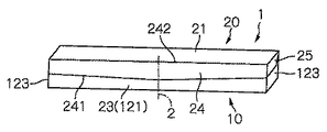
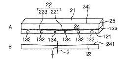
図面を参照し本発明の実施の形態を説明する。添付図面において、同様の部材には同じ符号を付し重複説明を省略する。図1は、本発明の1実施例のラップフィルム装置の使用開始前の概略斜視図であり、図2Aは、図1のラップフィルム装置の封止壁23を取り外した状態のラップフィルム装置の概略斜視図、図2Bは、箱前壁121から取り外された封止壁23の立面図である。図3は、図2Aのラップフィルム装置の蓋体が開放位置にある状態を示す概略斜視図である。図2Aは、箱前壁121上に封止壁23を接着する円形接着部132、134を示すが、図3の前壁121においては、円形接着部132、134が省略されている。
Embodiments of the present invention will be described with reference to the drawings. In the accompanying drawings, similar members are denoted by the same reference numerals, and redundant description is omitted. FIG. 1 is a schematic perspective view of a wrap film apparatus according to an embodiment of the present invention before the start of use, and FIG. 2A is a schematic view of the wrap film apparatus with the sealing
図4は、図3のラップフィルム装置の容器10からラップフィルムを使用者が人手61、62により引き出す状態を示す概略斜視断面図であり、図5は、図2Aのラップフィルム装置の箱前壁121、副前壁125等を展開して示す概略斜視図である。図1乃至図5に示すように、ラップフィルム装置1は、ラップフィルム36のロール30を容器10内に収容し、容器外へラップフィルム36を引出し可能とする構造を有する。容器10は、箱本体12及び蓋体20を含む。図4は、容器10を左手61で持ち右手62でラップフィルムを摘んで引出す状態を示す。フラップ50は対向する2つの箱端壁123間の距離の2等分線を含む位置に配置される。
4 is a schematic perspective cross-sectional view showing a state in which a user pulls out the wrap film from the
箱本体12は、箱前壁121、後壁122、底壁124及び対向する2つの箱端壁123、並びに箱前壁121、後壁122及び対向する2つの箱端壁123の上辺に囲まれた開口15を有する。更に箱本体12は、箱前壁上辺17に連結され箱本体内部をほぼ箱前壁121に沿って下方へ伸長する副前壁125、引出されたラップフィルム36がロール30上へ戻るのを防止する粘着剤層14(図3参照)、並びにラップフィルム及びその切断縁361を箱前壁121から離間させるフラップ50を備える。図5に示すように、蓋体20は、対応する2つの蓋端壁25を備える。また箱前壁121は、箱端壁123に固着可能な固着部136を備える。
The box body 12 is surrounded by a box
蓋体20は、上壁21、蓋前壁24、及び蓋前壁に固着された切断刃22を有する。上壁21は、後壁上辺16に連結される。切断刃22は、蓋体20が箱本体の開口15を閉じたとき箱前壁121の下方外面に隣接して配置されると共に下方へ突出する頂部221を有するV字形を有する。切断刃のV字形の頂部221は、対向する2つの蓋端壁25、25の間の距離の2等分線2の近辺に位置される。
The
図4は、容器10を左手61で持ち右手62でラップフィルム36を摘んで引出す状態を示す。フラップ50は対向する2つの箱端壁123間の距離の2等分線を含む位置に配置される。そのため、使用者に近接する箱端壁123とフラップ50(ラップフィルムの摘み位置)の間のラップフィルムの寸法(幅)と、使用者から離間する箱端壁123とフラップの間のラップフィルム寸法とがほぼ等しい。フラップ50が対向する2つの箱端壁123間の距離の2等分線を含む位置に配置される場合、図4とは手を逆した場合、即ち容器10を右手62で持ち左手61でラップフィルム36を摘んで引出す場合も、使用者に近接する箱端壁123とフラップ50(ラップフィルムの摘み位置)の間のラップフィルムの寸法(幅)と使用者から離間する箱端壁123とフラップ50の間のラップフィルム寸法がほぼ等しくなるので、従来の使い難さが生じない。
FIG. 4 shows a state in which the
図6は、本発明のラップフィルム装置のフラップ50を示す概略平面図であり、図7は、図6のフラップ50の概略斜視図である。ラップフィルム36及びその切断縁361を箱前壁121から離間させるためのフラップ50は、図6及び図7に示すように箱前壁121の一部分を副前壁125との連結部55を残して切り起して形成される。フラップ50の下縁51は、連結部55によって生じる弾性力により箱前壁121から離間される。フラップ50は、対向する2つの箱端壁123の間の距離の2等分線2を含むように配置される。また、フラップ50の形状は、下縁51が直線状または曲線状であってもよい。具体的には、フラップ50の形は、矩形(正方形、長方形)又はフラップ連結部55と下縁51を上底もしくは下底とした台形であってもよい。さらに、下縁51の中央部が凹形52となっていてもよい。凹形52は、図6に示すようにV字形とすることができる。また、凹形52は、図10に示すようにU字形とすることができる。この場合、凹形52の上に載ったラップフィルムがフラップ面からわずかに落ち込むことで、切断刃のV字形の頂部221の「刃当たり」が低減される効果を生む。加えて、フィルムをつまむ際に、凹形となっていることで、フィルムがつまみやすくなる効果を有する。凹形52は、U字形又はV字形の切り欠きを有することができる。図6及び図10において、フラップ50の連結部の長さWとフラップの最大高さH(フラップ連結部55とフラップ下縁51との間の最大寸法)の比W/Hは、0.5〜10、好ましくは、1〜6、更に好ましくは2〜5である。フラップの連結部の長さWがフラップの最大高さH、即ち連結部に垂直方向の寸法に対し、2以上である場合、連結部によりフラップに付与される弾性力が大きく、フラップの下縁が箱前壁121に付着したり十分に離間しない不都合が生じることを防ぐことができる。
FIG. 6 is a schematic plan view showing the
凹形52に係合するラップフィルム部分は、箱前壁121に近接して位置されるから、その外方を回動するV字形切断刃22の頂部221により押圧され損傷することが避けられる。引出されたラップフィルム36がロール30上へ戻るのを防止する粘着剤層14は、フラップ50の外面上に配置される。フラップ50の外面は、その下辺が箱前壁121外面から離間され、ラップフィルム36の切断縁に接触し易い位置にある故に、フラップ50の外面上の粘着剤層は、引出されたラップフィルム36の切断縁を確実に接着し保持する。
Since the wrap film portion engaged with the
図1、図2A及び図2Bに示すように、ラップフィルム装置1は、切断刃22の刃先を覆うと共に箱前壁121に剥離可能に固着される封止壁23を含む。封止壁23は、蓋前壁24の延長部により形成され、蓋前壁24に対し破断容易なつなぎ部241により接続される。つなぎ部241は、封止壁23が箱前壁121から剥離されたとき切断刃22の刃先223が露出されるように刃先223から所定寸法離間したV字形をなす。また、図2A及び図2Bに示すように、封止壁23は、箱前壁121に対し複数の接着部132,134により接着される。複数の接着部は、それぞれ円形を有し、隣接する円形の中心間の距離は等しくされ、更に、切断刃22のV字形の頂部221に近い位置にある接着部134の面積が頂部221から遠い位置にある接着部132の面積より小さくすることができる。
As shown in FIG. 1, FIG. 2A and FIG. 2B, the wrap film device 1 includes a sealing
図8は、蓋体20が幾分開放位置へ移動された図2Aのラップフィルム装置の二等分線2を含む概略断面図である。図8に示されるように、切断刃22のV字形の頂部221は、蓋体20が箱本体12の開口15を開放する方向へ後壁上辺16のまわりに角度R回転されると、蓋前壁24の上辺242からの垂直方向寸法Sが大きいほど、引き出されたラップフィルム36から大きな距離だけ離間する。寸法Sは、大きくすることにより、切断刃22のV字形の頂部221が引き出されたラップフィルム36を押圧し切断する「刃当たり」を減少させる傾向がある。
FIG. 8 is a schematic cross-sectional view including the
しかしながら、「刃当たり」を減少させるため、寸法Sを大きくすると、図2Bに示す封止壁23の線2付近の垂直寸法Tが小さくなる。封止壁23は、刃先223を隠すと共に、破れることなく箱前壁121表面から剥がれることが必要であり、またラップフィルム装置の使用前は、確実に箱前壁121表面に接着され、切断刃の刃先223を覆っていることを要求される。それ故、封止壁23の二等分線2付近の垂直寸法Tは、一定値以上、例えば10mm以上必要である。本発明においては、図2に示すように、切断刃22のV字形の頂部221に近い位置にある接着部134、134の面積が頂部221から遠い位置にある接着部132の面積より小さくすることができる。
However, when the dimension S is increased in order to reduce the “per edge”, the vertical dimension T near the
図8において、切断刃22のV字形の頂部221がフラップ下縁51と上下方向の位置が一致したときに、頂部221がフラップ50を押圧しないことが「刃当たり」を起こさない条件となる。また本発明のラップフィルム装置においては、上壁21の幅即ち後壁上辺16と蓋前壁上辺242との間の寸法をA、上壁21の水平方向からの回転角をR、蓋前壁上辺242から刃先の頂部221までの寸法をS、開口15の幅即ち後壁上辺16と折曲げ部55との間の寸法をB、フラップ折曲げ部55とフラップ下縁51との間の最大寸法をH、フラップ50の垂直方向からの回転角をX、とすると、回転角R、Xが、各々、次の式(1)及び(2)の範囲のある値を取るときに、
0<R<45°・・・(1)
0<X<45°・・・(2)
フラップ下縁の全域において、寸法A、B、S、Hが、
S×cosR=A×sinR+H×cosX・・・(3)
H×sinX≦(A×cosR+S×sinR)−B・・・(4)
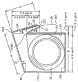
を満たすように、寸法A、B、S及びHが選択される。一例として、X=4°のとき切断刃のV字形の頂部221がフラップ下縁の最大寸法部分と接する角度は、A=43mm、B=43mm、S=27mm、H=20mmのときR=9°となる。そのとき、計算式から、H×sinX=3.10mm、(A×cosR+S×sinR)−B=3.70mmとなり、上式の関係を満足することがわかる。これによりラップフィルム装置の前述の「刃当たり」を防止することができる。
In FIG. 8, when the V-shaped
0 <R <45 ° (1)
0 <X <45 ° (2)
Dimensions A, B, S, and H are all over the lower edge of the flap.
S × cosR = A × sinR + H × cosX (3)
H × sinX ≦ (A × cosR + S × sinR) −B (4)
Dimensions A, B, S and H are selected to satisfy As an example, when X = 4 °, the angle at which the V-shaped
上記の式(4)は、H×sinX=(A×cosR+S×sinR)−B・・・(4b)の場合を含むが、この場合、切断刃の刃先223がフラップ下縁に接触するだけで、ラップフィルムを押圧しないので、柔軟なラップフィルムは、切断(損傷)されない。即ち、実質的に「刃当たり」を起こすことはない。本発明のラップフィルム装置において、フラップは、好ましくは、対向する2つの箱端壁の間の距離の2等分線を含むように配置される。そのため、使用者に近接する箱端壁とフラップ(ラップフィルムの摘み位置)の間のラップフィルムの寸法(幅)と、使用者から離間する箱端壁とフラップの間のラップフィルム寸法とがほぼ等しい。それ故、前記2等分線から離間した位置にフラップが設けられた場合の左利きの人又は右利きの人のいずれかに生じる不便を解消し、右利きの人及び左利きの人の両者に使い易いラップフィルム装置を提供することができる。
The above equation (4) includes the case of H × sinX = (A × cosR + S × sinR) −B (4b), but in this case, the
本発明のラップフィルム装置において、フラップの下縁は、凹形部を有する。このような構成を取ることにより、「刃当たり」、即ち、ラップフィルムにV字形切断刃の頂部付近が押圧しラップフィルムが切断される不具合の生じない改良されたラップフィルム装置を提供することができる。本発明のラップフィルム装置において、引出されたラップフィルムがロール上へ戻るのを防止する粘着剤層は、フラップ50の外面上に配置される。フラップの外面は、その下辺が箱前壁の外面から離間され、ラップフィルム及びその切断縁(端縁)に接触し易い位置にある故に、フラップの外面上の粘着剤層は、引出されたラップフィルムの端縁をより確実に粘着し保持する効果を奏する。
In the wrap film apparatus of the present invention, the lower edge of the flap has a concave portion. By taking such a configuration, it is possible to provide an improved wrap film apparatus that does not cause a problem that “per edge”, that is, the top portion of the V-shaped cutting blade is pressed against the wrap film and the wrap film is cut. it can. In the wrap film apparatus of the present invention, an adhesive layer for preventing the drawn wrap film from returning onto the roll is disposed on the outer surface of the
図9は、図3のラップフィルム装置の変形例であり、ラップフィルム装置の蓋体が開放位置にある状態を示す概略斜視図である。図9のラップフィルム装置においては、フラップ50が2つの箱端壁の間の距離の2等分線を含まない位置に配置されている。図9において、ロール30から引き出されたラップフィルム36の端部がロール30上への戻ることを防止するための粘着剤層14は、フラップ50の外面上に配置され、更に箱前壁121上に配置されている。
FIG. 9 is a schematic perspective view showing a state in which the lid of the wrap film apparatus is in an open position, which is a modification of the wrap film apparatus of FIG. In the wrap film apparatus of FIG. 9, the
本発明のラップフィルム装置において、封止壁は、蓋前壁の延長部により形成されると共に蓋前壁に対し破断容易なつなぎ部により接続される。封止壁が箱前壁から剥離されたとき切断刃の刃先が露出されるようにつなぎ部は、切断刃の刃先から所定寸法離間したV字形を有する。封止壁は、箱前壁に対し複数の接着部により接着され、切断刃のV字形の頂部に近い位置にある接着部の面積が頂部から遠い位置にある接着部の面積より小さい。それ故、封止壁は、刃先を隠すと共に、破れることなく箱前壁表面から剥がされることが可能であり、またラップフィルム装置の使用前は、確実に箱前壁表面に接着され、切断刃の刃先を覆うことができる利点を有する。 In the wrap film apparatus of the present invention, the sealing wall is formed by an extension of the front wall of the lid and is connected to the front wall of the lid by a connecting portion that is easily broken. The connecting portion has a V shape that is spaced from the cutting edge of the cutting blade by a predetermined dimension so that the cutting edge of the cutting blade is exposed when the sealing wall is peeled off from the front wall of the box. The sealing wall is bonded to the front wall of the box by a plurality of bonding portions, and the area of the bonding portion located near the V-shaped top of the cutting blade is smaller than the area of the bonding portion located far from the top. Therefore, the sealing wall hides the blade edge and can be peeled off from the surface of the box front wall without being torn, and is securely adhered to the surface of the box front wall before use of the wrap film apparatus, and the cutting blade The blade edge can be covered.
本発明においては、フラップの下縁の中央部付近が凹形とされ、フラップの連結部の長さWとフラップの最大高さHの比W/Hが2以上(図6、図10)である。即ち、フラップの連結部の寸法Wがフラップの最大高さH、即ち連結部に垂直方向の寸法に対し、2以上であることにより、連結部によりフラップに付与される弾性力が大きく、フラップの下縁が箱前壁121に付着したり十分に離間しない不都合が生じることを防ぐことができる。またフラップの凹形部分に係合するラップフィルム部分は、箱前壁に近接して位置され、その外方を回動するV字形切断刃の頂部に押圧し損傷することが避けられる。
In the present invention, the vicinity of the central portion of the lower edge of the flap is concave, and the ratio W / H between the length W of the flap connecting portion and the maximum height H of the flap is 2 or more (FIGS. 6 and 10). is there. That is, when the dimension W of the flap connecting portion is 2 or more with respect to the maximum height H of the flap, that is, the dimension perpendicular to the connecting portion, the elastic force applied to the flap by the connecting portion is large. It is possible to prevent a disadvantage that the lower edge adheres to the box
本発明の図3、図5、図6の実施例において、切断刃22のV字形の頂部221及びフラップの下縁51の凹形の中心が、対向する箱端壁123、123の間の距離の2等分線2上に位置されることにより、V字形の頂部221がフラップの下縁51から離間し、それにより、切断刃の頂部221がフラップの下縁51上のラップフィルムに押圧しないようにしている。しかしながら、2等分線2上に位置される代わりに、2等分線2と平行な直線2’(図10)上に切断刃22のV字形の頂部221及びフラップの下縁51の凹形の中心を位置することにより、切断刃の頂部221がフラップの下縁51上のラップフィルムを押圧しないようにすることができる。
3, 5, and 6 of the present invention, the V-shaped
1:ラップフィルム装置、2:2等分線、2’:凹形の中心線、10:容器、12:箱本体、14:粘着剤層、15:開口、16:後壁上辺、17:箱前壁上辺(折曲げ部)、20:蓋体、21:上壁、22:切断刃、23:封止壁、24:蓋前壁、25:蓋端壁、30:ロール、36:ラップフィルム、50:フラップ、51:フラップ下縁、52:凹形部、55:フラップ連結部(上辺)、57:半円形部分、61:左手、62:右手、121:箱前壁、122:後壁、123:箱端壁、124:底壁、125:副前壁、132、134:接着部、136:固着部、221:頂部、223:刃先、241:つなぎ部、242:蓋前壁上辺、361:ラップフィルム端縁、H:フラップの最大寸法、W:フラップの連結部の長さ。 1: wrap film apparatus, 2: 2 bisector, 2 ′: concave center line, 10: container, 12: box body, 14: adhesive layer, 15: opening, 16: upper side of rear wall, 17: box Front wall upper side (folded portion), 20: lid, 21: upper wall, 22: cutting blade, 23: sealing wall, 24: lid front wall, 25: lid end wall, 30: roll, 36: wrap film 50: flap, 51: flap lower edge, 52: concave part, 55: flap connecting part (upper side), 57: semicircular part, 61: left hand, 62: right hand, 121: front wall of box, 122: rear wall 123: Box end wall, 124: Bottom wall, 125: Sub-front wall, 132, 134: Adhesive part, 136: Adhering part, 221: Top part, 223: Cutting edge, 241: Connecting part, 242: Upper side of lid front wall, 361: Wrapping film edge, H: Maximum size of flap, W: Length of connecting portion of flap.
Claims (11)
容器は、箱本体(12)及び蓋体(20)を含み、
箱本体(12)は、
箱前壁(121)と、
後壁(122)と、
底壁(124)と、
対向する2つの箱端壁(123)と、
箱前壁上辺、後壁上辺、及び前記2つの箱端壁上辺に囲まれた開口(15)と、
箱前壁上辺に連結され箱本体内部を箱前壁に沿って下方へ伸長する副前壁(125)と、
ラップフィルム端縁(361)を箱前壁から離間させるフラップ(50)とを有し、
蓋体は、上壁(21)、蓋前壁(24)、及び蓋前壁に固着された切断刃(22)を有し、上壁(21)は後壁上辺(16)に連結され、切断刃の刃先(223)は、蓋体が開口を閉じたとき箱前壁の下方外面に隣接して配置され、
前記フラップ(50)は、副前壁と連結するフラップ連結部(55)を有するように箱前壁(121)の一部分を切り起して形成され、
引出されたラップフィルム(36)がロール上へ戻るのを防止する粘着剤層(14)が、箱前壁(121)の外面又は前記フラップ(50)の外面上に配置されており、
上壁(21)の幅、即ち後壁上辺(16)と蓋前壁上辺(242)との間の寸法をA、上壁(21)の水平方向からの回転角をR、蓋前壁上辺(242)から刃先の頂部(221)までの寸法をS、開口(15)の幅、即ち後壁上辺(16)と箱前壁上辺(17)との間の寸法をB、フラップ連結部(55)とフラップ下縁(51)との間の最大寸法をH、フラップ(50)の垂直方向からの回転角をX、とすると、回転角R、Xが、各々、次の式(1)及び(2)の範囲のある値を取るときに、
0<R<45°・・・(1)
0<X<45°・・・(2)
フラップ下縁の全域において、
S×cosR=A×sinR+H×cosX・・・(3)
H×sinX≦(A×cosR+S×sinR)−B・・・(4)
が満足されており、
前記フラップ(50)は、前記折曲げ部(55)の復元力により箱前壁から前記回転角Xだけ回転され、前記フラップ(50)が前記折曲げ部(55)の復元力により箱前壁から前記回転角Xだけ回転された状態で、蓋体(20)が開口(15)を閉じるとき、前記刃先(223)がフラップ下縁(51)に接触するだけでフラップ(50)を押圧しないことを特徴とするラップフィルム装置。 A wrap film apparatus that accommodates a roll (30) of a wrap film in a container (10) and enables the wrap film to be drawn out of the container,
The container includes a box body (12) and a lid (20),
The box body (12)
The front wall of the box (121),
The rear wall (122);
A bottom wall (124);
Two opposing box end walls (123);
An opening (15) surrounded by an upper side of the box front wall, an upper side of the rear wall, and an upper side of the two box end walls;
A sub-front wall (125) connected to the upper side of the box front wall and extending downward along the box front wall inside the box body;
A flap (50) for separating the wrap film edge (361) from the box front wall;
The lid body has an upper wall (21), a lid front wall (24), and a cutting blade (22) fixed to the lid front wall, and the upper wall (21) is connected to the rear wall upper side (16), The cutting edge (223) of the cutting blade is disposed adjacent to the lower outer surface of the front wall of the box when the lid closes the opening,
The flap (50) is formed by cutting and raising a part of the box front wall (121) to have a flap connection part (55) connected to the sub-front wall,
An adhesive layer (14) for preventing the drawn wrap film (36) from returning onto the roll is disposed on the outer surface of the box front wall (121) or the outer surface of the flap (50),
The width of the upper wall (21), that is, the dimension between the rear wall upper side (16) and the lid front wall upper side (242) is A, the rotation angle of the upper wall (21) from the horizontal direction is R, and the lid front wall upper side The dimension from (242) to the top (221) of the blade edge is S, the width of the opening (15), that is, the dimension between the rear wall upper side (16) and the box front wall upper side (17) is B, and the flap connecting part ( 55) and the lower edge of the flap (51) is H, and the rotation angle of the flap (50) from the vertical direction is X, the rotation angles R and X are respectively expressed by the following formula (1): And when taking a value in the range of (2)
0 <R <45 ° (1)
0 <X <45 ° (2)
In the whole area of the lower edge of the flap,
S × cosR = A × sinR + H × cosX (3)
H × sinX ≦ (A × cosR + S × sinR) −B (4)
Is satisfied,
The flap (50) is rotated by the rotation angle X from the front wall of the box by the restoring force of the bent portion (55), and the flap (50) is rotated by the restoring force of the bent portion (55). When the lid (20) closes the opening (15) while being rotated by the rotation angle X , the blade edge (223) just contacts the flap lower edge (51) and does not press the flap (50). The wrap film apparatus characterized by the above-mentioned.
フラップ連結部(55)は前記折曲げ部の一部分であり、
切断刃(22)のV字形の頂部(221)は、対向する2つの箱端壁(123、123)の間の距離の2等分線(2)の近辺に位置されていることを特徴とする請求項5のラップフィルム装置。 The box front wall (121) and the sub-front wall (125) are made of a single cardboard, and the box front wall upper side (17) is a bent portion of the cardboard,
The flap connecting part (55) is a part of the bent part,
The V-shaped top (221) of the cutting blade (22) is located in the vicinity of the bisector (2) of the distance between the two box end walls (123, 123) facing each other. The wrap film apparatus according to claim 5.
Priority Applications (5)
| Application Number | Priority Date | Filing Date | Title |
|---|---|---|---|
| JP2008022525A JP5465386B2 (en) | 2007-02-27 | 2008-02-01 | Wrap film device with flap |
| TW097106090A TWI460106B (en) | 2007-02-27 | 2008-02-21 | Packaging film with lugs |
| KR1020080017081A KR101269735B1 (en) | 2007-02-27 | 2008-02-26 | Lap film device with flap |
| CN2008100825189A CN101254874B (en) | 2007-02-27 | 2008-02-27 | Packing film device with fins |
| HK09101337.1A HK1124819A1 (en) | 2007-02-27 | 2009-02-12 | Package film device with wing |
Applications Claiming Priority (5)
| Application Number | Priority Date | Filing Date | Title |
|---|---|---|---|
| JP2007046509 | 2007-02-27 | ||
| JP2007046516 | 2007-02-27 | ||
| JP2007046516 | 2007-02-27 | ||
| JP2007046509 | 2007-02-27 | ||
| JP2008022525A JP5465386B2 (en) | 2007-02-27 | 2008-02-01 | Wrap film device with flap |
Publications (3)
| Publication Number | Publication Date |
|---|---|
| JP2008239252A JP2008239252A (en) | 2008-10-09 |
| JP2008239252A5 JP2008239252A5 (en) | 2011-07-14 |
| JP5465386B2 true JP5465386B2 (en) | 2014-04-09 |
Family
ID=39911058
Family Applications (1)
| Application Number | Title | Priority Date | Filing Date |
|---|---|---|---|
| JP2008022525A Active JP5465386B2 (en) | 2007-02-27 | 2008-02-01 | Wrap film device with flap |
Country Status (4)
| Country | Link |
|---|---|
| JP (1) | JP5465386B2 (en) |
| KR (1) | KR101269735B1 (en) |
| HK (1) | HK1124819A1 (en) |
| TW (1) | TWI460106B (en) |
Families Citing this family (3)
| Publication number | Priority date | Publication date | Assignee | Title |
|---|---|---|---|---|
| JP2012101814A (en) * | 2010-11-09 | 2012-05-31 | Kureha Corp | Wrap film storage container and wrap film supplying tool |
| JP2013063802A (en) * | 2011-09-01 | 2013-04-11 | Kureha Corp | Wound body storage box and storage box containing wound body |
| JP5083852B1 (en) * | 2012-05-08 | 2012-11-28 | 哲夫 村山 | Wrap film container |
Family Cites Families (7)
| Publication number | Priority date | Publication date | Assignee | Title |
|---|---|---|---|---|
| JPH0977082A (en) * | 1995-09-08 | 1997-03-25 | Masahide Nakamura | Wrap-cut holder |
| JP3827761B2 (en) * | 1996-01-25 | 2006-09-27 | 株式会社クレハ | Packaging container |
| JP2000109091A (en) * | 1998-10-01 | 2000-04-18 | Kazusato Sato | Take-out function for wrap |
| JP2001031103A (en) * | 1999-07-16 | 2001-02-06 | Furubayashi Shiko Co Ltd | Sheet storage container with cutting edge |
| JP2001031104A (en) * | 1999-07-19 | 2001-02-06 | Kao Corp | Wrapping carton |
| JP4753481B2 (en) * | 2001-03-15 | 2011-08-24 | 株式会社クレハ | Packaging container |
| JP4326431B2 (en) * | 2003-10-15 | 2009-09-09 | 株式会社クレハ | Packaging film container |
-
2008
- 2008-02-01 JP JP2008022525A patent/JP5465386B2/en active Active
- 2008-02-21 TW TW097106090A patent/TWI460106B/en active
- 2008-02-26 KR KR1020080017081A patent/KR101269735B1/en not_active IP Right Cessation
-
2009
- 2009-02-12 HK HK09101337.1A patent/HK1124819A1/en not_active IP Right Cessation
Also Published As
| Publication number | Publication date |
|---|---|
| KR20080079608A (en) | 2008-09-01 |
| TWI460106B (en) | 2014-11-11 |
| HK1124819A1 (en) | 2009-07-24 |
| TW200902391A (en) | 2009-01-16 |
| JP2008239252A (en) | 2008-10-09 |
| KR101269735B1 (en) | 2013-05-30 |
Similar Documents
| Publication | Publication Date | Title |
|---|---|---|
| US7703602B2 (en) | Easy-open encasement | |
| JP4671675B2 (en) | Easy-open packaging | |
| JP2008239250A (en) | Wrap film device with flap | |
| JP4753481B2 (en) | Packaging container | |
| JP2008239251A (en) | Wrap film device with flap | |
| JPH09117387A (en) | Packing body having sheet-shaped opening/closing lid | |
| JP5465386B2 (en) | Wrap film device with flap | |
| TWI482723B (en) | Box for containing rolled film and box with rolled film | |
| JP4632334B2 (en) | Packaging container | |
| JPH0829791B2 (en) | Tape package | |
| JP4494915B2 (en) | Easy-open packaging | |
| JP2011225238A (en) | Open label of bag | |
| JP5670663B2 (en) | Storage case | |
| JPH0710762U (en) | Label for package lid | |
| KR101257312B1 (en) | Pack of wet tissues | |
| EP3863942B1 (en) | A package for sheet products | |
| WO2002074640A1 (en) | Packing container | |
| JP2020083476A (en) | Bag for sandwich packing | |
| JP2004142817A (en) | Housing box for roll of wrapping film | |
| JP2008260564A (en) | Wrap film roll storage case | |
| JP2015003760A (en) | Wrap film package box | |
| JPH04112058U (en) | Blister pack for storing multiple products | |
| JP2008127101A (en) | Food wrap film container | |
| JP2004276948A5 (en) | ||
| JP2000296841A (en) | Packaging container |
Legal Events
| Date | Code | Title | Description |
|---|---|---|---|
| A621 | Written request for application examination |
Free format text: JAPANESE INTERMEDIATE CODE: A621 Effective date: 20110118 |
|
| A521 | Request for written amendment filed |
Free format text: JAPANESE INTERMEDIATE CODE: A523 Effective date: 20110526 |
|
| RD04 | Notification of resignation of power of attorney |
Free format text: JAPANESE INTERMEDIATE CODE: A7424 Effective date: 20110819 |
|
| A977 | Report on retrieval |
Free format text: JAPANESE INTERMEDIATE CODE: A971007 Effective date: 20120802 |
|
| A131 | Notification of reasons for refusal |
Free format text: JAPANESE INTERMEDIATE CODE: A131 Effective date: 20120926 |
|
| A521 | Request for written amendment filed |
Free format text: JAPANESE INTERMEDIATE CODE: A523 Effective date: 20121119 |
|
| A131 | Notification of reasons for refusal |
Free format text: JAPANESE INTERMEDIATE CODE: A131 Effective date: 20130515 |
|
| A521 | Request for written amendment filed |
Free format text: JAPANESE INTERMEDIATE CODE: A523 Effective date: 20130628 |
|
| TRDD | Decision of grant or rejection written | ||
| A01 | Written decision to grant a patent or to grant a registration (utility model) |
Free format text: JAPANESE INTERMEDIATE CODE: A01 Effective date: 20131224 |
|
| A61 | First payment of annual fees (during grant procedure) |
Free format text: JAPANESE INTERMEDIATE CODE: A61 Effective date: 20140122 |
|
| R150 | Certificate of patent or registration of utility model |
Ref document number: 5465386 Country of ref document: JP Free format text: JAPANESE INTERMEDIATE CODE: R150 Free format text: JAPANESE INTERMEDIATE CODE: R150 |
|
| R250 | Receipt of annual fees |
Free format text: JAPANESE INTERMEDIATE CODE: R250 |
|
| R250 | Receipt of annual fees |
Free format text: JAPANESE INTERMEDIATE CODE: R250 |
|
| R250 | Receipt of annual fees |
Free format text: JAPANESE INTERMEDIATE CODE: R250 |
|
| R250 | Receipt of annual fees |
Free format text: JAPANESE INTERMEDIATE CODE: R250 |
|
| R250 | Receipt of annual fees |
Free format text: JAPANESE INTERMEDIATE CODE: R250 |
|
| R250 | Receipt of annual fees |
Free format text: JAPANESE INTERMEDIATE CODE: R250 |
|
| R250 | Receipt of annual fees |
Free format text: JAPANESE INTERMEDIATE CODE: R250 |
|
| R250 | Receipt of annual fees |
Free format text: JAPANESE INTERMEDIATE CODE: R250 |