JP5464654B2 - LONG MEDICAL DEVICE WITH DEFORMABLE TIP AND MANUFACTURING METHOD THEREOF - Google Patents
LONG MEDICAL DEVICE WITH DEFORMABLE TIP AND MANUFACTURING METHOD THEREOF Download PDFInfo
- Publication number
- JP5464654B2 JP5464654B2 JP2009525678A JP2009525678A JP5464654B2 JP 5464654 B2 JP5464654 B2 JP 5464654B2 JP 2009525678 A JP2009525678 A JP 2009525678A JP 2009525678 A JP2009525678 A JP 2009525678A JP 5464654 B2 JP5464654 B2 JP 5464654B2
- Authority
- JP
- Japan
- Prior art keywords
- tubular member
- region
- temperature
- tip
- medical device
- Prior art date
- Legal status (The legal status is an assumption and is not a legal conclusion. Google has not performed a legal analysis and makes no representation as to the accuracy of the status listed.)
- Active
Links
Images


Classifications
-
- A—HUMAN NECESSITIES
- A61—MEDICAL OR VETERINARY SCIENCE; HYGIENE
- A61M—DEVICES FOR INTRODUCING MEDIA INTO, OR ONTO, THE BODY; DEVICES FOR TRANSDUCING BODY MEDIA OR FOR TAKING MEDIA FROM THE BODY; DEVICES FOR PRODUCING OR ENDING SLEEP OR STUPOR
- A61M25/00—Catheters; Hollow probes
- A61M25/01—Introducing, guiding, advancing, emplacing or holding catheters
- A61M25/09—Guide wires
-
- A—HUMAN NECESSITIES
- A61—MEDICAL OR VETERINARY SCIENCE; HYGIENE
- A61L—METHODS OR APPARATUS FOR STERILISING MATERIALS OR OBJECTS IN GENERAL; DISINFECTION, STERILISATION OR DEODORISATION OF AIR; CHEMICAL ASPECTS OF BANDAGES, DRESSINGS, ABSORBENT PADS OR SURGICAL ARTICLES; MATERIALS FOR BANDAGES, DRESSINGS, ABSORBENT PADS OR SURGICAL ARTICLES
- A61L29/00—Materials for catheters, medical tubing, cannulae, or endoscopes or for coating catheters
- A61L29/02—Inorganic materials
-
- A—HUMAN NECESSITIES
- A61—MEDICAL OR VETERINARY SCIENCE; HYGIENE
- A61L—METHODS OR APPARATUS FOR STERILISING MATERIALS OR OBJECTS IN GENERAL; DISINFECTION, STERILISATION OR DEODORISATION OF AIR; CHEMICAL ASPECTS OF BANDAGES, DRESSINGS, ABSORBENT PADS OR SURGICAL ARTICLES; MATERIALS FOR BANDAGES, DRESSINGS, ABSORBENT PADS OR SURGICAL ARTICLES
- A61L31/00—Materials for other surgical articles, e.g. stents, stent-grafts, shunts, surgical drapes, guide wires, materials for adhesion prevention, occluding devices, surgical gloves, tissue fixation devices
- A61L31/02—Inorganic materials
- A61L31/022—Metals or alloys
-
- A—HUMAN NECESSITIES
- A61—MEDICAL OR VETERINARY SCIENCE; HYGIENE
- A61L—METHODS OR APPARATUS FOR STERILISING MATERIALS OR OBJECTS IN GENERAL; DISINFECTION, STERILISATION OR DEODORISATION OF AIR; CHEMICAL ASPECTS OF BANDAGES, DRESSINGS, ABSORBENT PADS OR SURGICAL ARTICLES; MATERIALS FOR BANDAGES, DRESSINGS, ABSORBENT PADS OR SURGICAL ARTICLES
- A61L31/00—Materials for other surgical articles, e.g. stents, stent-grafts, shunts, surgical drapes, guide wires, materials for adhesion prevention, occluding devices, surgical gloves, tissue fixation devices
- A61L31/14—Materials characterised by their function or physical properties, e.g. injectable or lubricating compositions, shape-memory materials, surface modified materials
-
- A—HUMAN NECESSITIES
- A61—MEDICAL OR VETERINARY SCIENCE; HYGIENE
- A61M—DEVICES FOR INTRODUCING MEDIA INTO, OR ONTO, THE BODY; DEVICES FOR TRANSDUCING BODY MEDIA OR FOR TAKING MEDIA FROM THE BODY; DEVICES FOR PRODUCING OR ENDING SLEEP OR STUPOR
- A61M25/00—Catheters; Hollow probes
- A61M25/0021—Catheters; Hollow probes characterised by the form of the tubing
- A61M25/0041—Catheters; Hollow probes characterised by the form of the tubing pre-formed, e.g. specially adapted to fit with the anatomy of body channels
-
- A—HUMAN NECESSITIES
- A61—MEDICAL OR VETERINARY SCIENCE; HYGIENE
- A61M—DEVICES FOR INTRODUCING MEDIA INTO, OR ONTO, THE BODY; DEVICES FOR TRANSDUCING BODY MEDIA OR FOR TAKING MEDIA FROM THE BODY; DEVICES FOR PRODUCING OR ENDING SLEEP OR STUPOR
- A61M25/00—Catheters; Hollow probes
- A61M25/0043—Catheters; Hollow probes characterised by structural features
- A61M25/005—Catheters; Hollow probes characterised by structural features with embedded materials for reinforcement, e.g. wires, coils, braids
- A61M25/0051—Catheters; Hollow probes characterised by structural features with embedded materials for reinforcement, e.g. wires, coils, braids made from fenestrated or weakened tubing layer
-
- A—HUMAN NECESSITIES
- A61—MEDICAL OR VETERINARY SCIENCE; HYGIENE
- A61M—DEVICES FOR INTRODUCING MEDIA INTO, OR ONTO, THE BODY; DEVICES FOR TRANSDUCING BODY MEDIA OR FOR TAKING MEDIA FROM THE BODY; DEVICES FOR PRODUCING OR ENDING SLEEP OR STUPOR
- A61M25/00—Catheters; Hollow probes
- A61M25/0067—Catheters; Hollow probes characterised by the distal end, e.g. tips
- A61M25/008—Strength or flexibility characteristics of the catheter tip
-
- A—HUMAN NECESSITIES
- A61—MEDICAL OR VETERINARY SCIENCE; HYGIENE
- A61M—DEVICES FOR INTRODUCING MEDIA INTO, OR ONTO, THE BODY; DEVICES FOR TRANSDUCING BODY MEDIA OR FOR TAKING MEDIA FROM THE BODY; DEVICES FOR PRODUCING OR ENDING SLEEP OR STUPOR
- A61M25/00—Catheters; Hollow probes
- A61M25/01—Introducing, guiding, advancing, emplacing or holding catheters
- A61M25/09—Guide wires
- A61M25/09016—Guide wires with mandrils
- A61M25/09033—Guide wires with mandrils with fixed mandrils, e.g. mandrils fixed to tip; Tensionable wires
-
- A—HUMAN NECESSITIES
- A61—MEDICAL OR VETERINARY SCIENCE; HYGIENE
- A61L—METHODS OR APPARATUS FOR STERILISING MATERIALS OR OBJECTS IN GENERAL; DISINFECTION, STERILISATION OR DEODORISATION OF AIR; CHEMICAL ASPECTS OF BANDAGES, DRESSINGS, ABSORBENT PADS OR SURGICAL ARTICLES; MATERIALS FOR BANDAGES, DRESSINGS, ABSORBENT PADS OR SURGICAL ARTICLES
- A61L2400/00—Materials characterised by their function or physical properties
- A61L2400/16—Materials with shape-memory or superelastic properties
-
- A—HUMAN NECESSITIES
- A61—MEDICAL OR VETERINARY SCIENCE; HYGIENE
- A61M—DEVICES FOR INTRODUCING MEDIA INTO, OR ONTO, THE BODY; DEVICES FOR TRANSDUCING BODY MEDIA OR FOR TAKING MEDIA FROM THE BODY; DEVICES FOR PRODUCING OR ENDING SLEEP OR STUPOR
- A61M25/00—Catheters; Hollow probes
- A61M25/01—Introducing, guiding, advancing, emplacing or holding catheters
- A61M25/09—Guide wires
- A61M2025/09058—Basic structures of guide wires
- A61M2025/09075—Basic structures of guide wires having a core without a coil possibly combined with a sheath
-
- A—HUMAN NECESSITIES
- A61—MEDICAL OR VETERINARY SCIENCE; HYGIENE
- A61M—DEVICES FOR INTRODUCING MEDIA INTO, OR ONTO, THE BODY; DEVICES FOR TRANSDUCING BODY MEDIA OR FOR TAKING MEDIA FROM THE BODY; DEVICES FOR PRODUCING OR ENDING SLEEP OR STUPOR
- A61M25/00—Catheters; Hollow probes
- A61M25/01—Introducing, guiding, advancing, emplacing or holding catheters
- A61M25/09—Guide wires
- A61M2025/09108—Methods for making a guide wire
-
- A—HUMAN NECESSITIES
- A61—MEDICAL OR VETERINARY SCIENCE; HYGIENE
- A61M—DEVICES FOR INTRODUCING MEDIA INTO, OR ONTO, THE BODY; DEVICES FOR TRANSDUCING BODY MEDIA OR FOR TAKING MEDIA FROM THE BODY; DEVICES FOR PRODUCING OR ENDING SLEEP OR STUPOR
- A61M25/00—Catheters; Hollow probes
- A61M25/01—Introducing, guiding, advancing, emplacing or holding catheters
- A61M25/09—Guide wires
- A61M2025/09133—Guide wires having specific material compositions or coatings; Materials with specific mechanical behaviours, e.g. stiffness, strength to transmit torque
- A61M2025/09141—Guide wires having specific material compositions or coatings; Materials with specific mechanical behaviours, e.g. stiffness, strength to transmit torque made of shape memory alloys which take a particular shape at a certain temperature
-
- A—HUMAN NECESSITIES
- A61—MEDICAL OR VETERINARY SCIENCE; HYGIENE
- A61M—DEVICES FOR INTRODUCING MEDIA INTO, OR ONTO, THE BODY; DEVICES FOR TRANSDUCING BODY MEDIA OR FOR TAKING MEDIA FROM THE BODY; DEVICES FOR PRODUCING OR ENDING SLEEP OR STUPOR
- A61M25/00—Catheters; Hollow probes
- A61M25/01—Introducing, guiding, advancing, emplacing or holding catheters
- A61M25/09—Guide wires
- A61M2025/0915—Guide wires having features for changing the stiffness
Abstract
Description
本発明は、カテーテル、ガイドワイヤなどのような長尺状医療器具に関する。より詳細には、本発明は、そのような医療器具内における管状構造に関する。 The present invention relates to elongated medical devices such as catheters, guide wires and the like. More particularly, the present invention relates to a tubular structure within such a medical device.
カテーテル及びガイドワイヤのような多種多様の医療器具が開発されてきた。カテーテル及びガイドワイヤのような医療器具は血管内処置を行うために使用することができる。これらの血管内処置は、より侵襲性の高い外科的処置を回避するために、一般的に使用されるようになってきた。患者の解剖学的構造が極度に蛇行していることがあるため、長尺状医療器具において特定の性能特徴を有することが望ましい場合がある。カテーテル及びガイドワイヤのような長尺状医療器具のための多くの様々な構造及びアセンブリが知られており、それらの構造及びアセンブリは特定の長所と短所とをそれぞれ有している。しかしながら、従来のものに代わる構造及びアセンブリを提供することが引き続き必要とされている。 A wide variety of medical devices such as catheters and guidewires have been developed. Medical devices such as catheters and guidewires can be used to perform endovascular procedures. These endovascular procedures have become commonly used to avoid more invasive surgical procedures. It may be desirable to have certain performance characteristics in an elongated medical device because the patient's anatomy may be extremely serpentine. Many different structures and assemblies are known for elongate medical devices such as catheters and guidewires, each having particular advantages and disadvantages. However, there is a continuing need to provide structures and assemblies that replace the conventional ones.
本発明は、従来のものに代わる医療器具構造及びアセンブリのいくつかの代替の設計、材料、並びに製造方法及び使用方法を提供する。 The present invention provides several alternative designs, materials, and methods of manufacture and use for alternative medical device structures and assemblies.
従って、一実施形態による医療用ガイドワイヤは、基端領域、先端領域、ならびにこれら先端領域及び基端領域の間に位置する中間領域を備えた長尺状コア部材と、1つ以上の合金区域を備えた長尺状管状部材であって、該管状部材は管腔を画定するとともに、先端部及び基端部を有し、該管状部材の基端部は前記コア部材に接続され、前記コア部材は少なくとも部分的に前記管腔内に配置される、長尺状管状部材と、を備える。前記1つ以上の合金区域の各々はオーステナイト状態とマルテンサイト状態とを有し、前記管状部材の1つ以上の合金は、第1弾性領域において第1温度にてマルテンサイト状態からオーステナイト状態への転移を終了し、第1変形可能領域において第2温度にてマルテンサイト状態からオーステナイト状態への転移を終了し、前記第1温度は15℃より低く、第2温度は42℃より高く、第1変形可能領域は、前記管状部材の先端部を形成し、第1弾性領域は第1変形可能領域の基端側に配置される。医療用ガイドワイヤは、カテーテル、又は管状部材を備えた他の長尺状医療器具とすることができる。 Accordingly, a medical guidewire according to one embodiment includes an elongate core member having a proximal region, a distal region, and an intermediate region located between the distal and proximal regions, and one or more alloy sections. The tubular member defines a lumen, and has a distal end portion and a proximal end portion, and the proximal end portion of the tubular member is connected to the core member, and the core The member comprises an elongate tubular member disposed at least partially within the lumen. Each of the one or more alloy zones has an austenite state and a martensite state, and the one or more alloys of the tubular member transition from a martensite state to an austenite state at a first temperature in a first elastic region. The transition is terminated, and the transition from the martensite state to the austenite state is terminated at the second temperature in the first deformable region, the first temperature is lower than 15 ° C, the second temperature is higher than 42 ° C, The deformable region forms a distal end portion of the tubular member, and the first elastic region is disposed on the proximal end side of the first deformable region. The medical guidewire can be a catheter or other elongate medical device with a tubular member.
別の実施形態の例は、管状部材、例えば上記段落に記載した管状部材のうちの任意のものを有することができ、さらにコア部材を備えることができる。コア部材は中実断面を有することができ、コア部材の少なくとも一部は管状部材によって画定される管腔内に配置され得る。管状部材の基端部は、取り付け点においてコア部材に取り付けることができ、この取り付け点からコア部材の周囲を先端側に延びることができる。コア部材は、ステンレス鋼のような金属を含み得る。 Another example embodiment can have a tubular member, such as any of the tubular members described in the paragraphs above, and can further comprise a core member. The core member can have a solid cross section and at least a portion of the core member can be disposed within a lumen defined by the tubular member. The proximal end portion of the tubular member can be attached to the core member at an attachment point, and can extend from the attachment point to the distal end side around the core member. The core member may include a metal such as stainless steel.
別の実施形態による、体内用医療器具を製造する方法は、基端領域、中間領域及び先端領域を有するコア部材を提供する工程と、1つ以上の合金を含む管状部材を提供する工程と、前記管状部材は管腔を画定するとともに、基端区域及び先端区域を有することと、前記コア部材を少なくとも部分的に前記管状部材の管腔内に配置する工程と、前記管状部材の基端区域を前記コア部材に取り付ける工程と、前記管状部材の第1変形可能領域におけるマルテンサイト状態からオーステナイト状態への転移終了後の温度が、前記管状部材の基端区域におけるマルテンサイト状態からオーステナイト状態への転移終了後の温度より高くなるように変更するために、前記管状部材の第1変形可能領域を処理する工程と、を含む。前記管状部材はマルテンサイト状態からオーステナイト状態への転移終了直後の初期温度を有し、前記管状部材を処理する工程は、管状部材の先端区域を、該先端区域がマルテンサイト状態からオーステナイト状態への転移終了後の温度が42℃より高くなるまでサンドバス内に配置することを含む。 According to another embodiment, a method of manufacturing an in- vivo medical device includes providing a core member having a proximal region, an intermediate region, and a distal region, and providing a tubular member that includes one or more alloys. The tubular member defines a lumen and has a proximal section and a distal section; positioning the core member at least partially within the lumen of the tubular member; and a proximal section of the tubular member The temperature after the transition from the martensite state to the austenite state in the first deformable region of the tubular member is changed from the martensite state to the austenite state in the proximal end region of the tubular member. Processing the first deformable region of the tubular member to change to be higher than the temperature after completion of the transition. The tubular member has an initial temperature immediately after completion of the transition from the martensite state to the austenite state, and the step of treating the tubular member includes the tip region of the tubular member being changed from the martensite state to the austenite state. Placing in a sand bath until the temperature after the transition is over 42 ° C.
いくつかの実施形態に関する上記概要は、本発明の各開示された実施形態又はすべての実施を記載するようには意図されない。図面及びそれに続く詳細な説明は、これら及び他の実施形態をより詳しく例示している。 The above summary of some embodiments is not intended to describe each disclosed embodiment or every implementation of the present invention. The drawings and the following detailed description illustrate these and other embodiments in more detail.
本発明は、添付の図面に関する本発明の様々な実施形態の以下の詳細な説明を参酌することによって、より完全に理解され得る。 The present invention may be understood more fully by reference to the following detailed description of various embodiments of the invention with reference to the accompanying drawings.
本発明は様々な改変及び代替形態にて実施可能であるが、それらのいくつかの詳細を例として図面に示し、詳細に説明する。しかしながら、これは、本発明を特定の実施形態に限定することを意図するものではなく、本発明は、その趣旨及び範囲内に含まれるすべての改変物、均等物、及び代替物にも及ぶものである。 While the invention is amenable to various modifications and alternative forms, specifics thereof are shown by way of example in the drawings and will be described in detail. However, this is not intended to limit the invention to any particular embodiment, and the invention extends to all modifications, equivalents, and alternatives falling within the spirit and scope of the invention. It is.
以下に定義される用語については、特許請求の範囲又は本明細書の他の箇所において異なる定義がなされない限りにおいて、これらの定義が適用されるものとする。
「ポリマー」という用語は、ポリマー、コポリマー(例えば2つ以上の異なるモノマーを用いて形成されたポリマー)、オリゴマー及びそれらの組み合わせ、ならびに、例えば共押出成形又はエステル交換反応を含む反応によって、混和性ブレンド(miscible blend)に形成され得るポリマー、オリゴマー、又はコポリマーを含む。異なる記載のない限りにおいて、ブロックコポリマー及びランダムコポリマーも含まれる。
For the terms defined below, these definitions shall apply unless otherwise defined in the claims or elsewhere in this specification.
The term “polymer” is miscible by polymers, copolymers (eg, polymers formed using two or more different monomers), oligomers and combinations thereof, and reactions including, for example, coextrusion or transesterification reactions. Includes polymers, oligomers, or copolymers that can be formed into miscible blends. Unless stated otherwise, block copolymers and random copolymers are also included.
本願において、すべての数値は、明示的に示されているか否かに関わらず、「約」という語が付されているものとみなされる。「約」という語は、一般的に、記載される値と同等である(すなわち、同じ機能又は結果を有する)と当業者がみなすであろう数値範囲をいう。多くの場合において、「約」という語は、最も近い有効数字に四捨五入した数を含み得る。 In this application, all numerical values are considered to be accompanied by the word “about”, whether or not explicitly indicated. The term “about” generally refers to a numerical range that would be considered by one of ordinary skill in the art to be equivalent to the recited value (ie, have the same function or result). In many cases, the term “about” may include numbers rounded to the nearest significant figure.
上下限値による数値範囲の記載は、その範囲内の数値をすべて含む(例えば、1〜5は、1、1.5、2、2.75、3、3.80、4及び5を含む)。
本明細書及び添付の特許請求の範囲において用いられる場合、単数形「a」「an」及び「the」は、内容が明らかに異なる場合を除き、複数の対象物を含む。本明細書及び添付の特許請求の範囲において用いられる場合、「又は」という語は、概して、内容が明らかに異なる場合を除き、「及び/又は」の意味を含んで使用される。
The description of a numerical range by upper and lower limits includes all numerical values within the range (for example, 1 to 5 includes 1, 1.5, 2, 2.75, 3, 3.80, 4 and 5). .
As used in this specification and the appended claims, the singular forms “a”, “an”, and “the” include plural objects unless the content clearly differs. As used herein and in the appended claims, the term “or” is generally used in its sense including the meaning of “and / or” unless the content clearly differs.
以下の記載は図面を参照して読まれるべきであり、各図面において、類似する符号は類似する要素を示す。図面は、必ずしも寸法比率が等しいものではなく、特許が請求される発明の例示的な実施形態を表すものである。 The following description should be read with reference to the drawings, in which like numerals indicate like elements. The drawings are not necessarily to scale, but represent exemplary embodiments of the claimed invention.
例えば、本願に記載する特定の実施形態におけるガイドワイヤ及びカテーテルに関して説明するが、本発明は、開口又は管腔を介して患者の解剖学的構造内に進められるように構成された様々な医療器具に適用することができる。例えば、本発明は、固定ワイヤ器具、様々なカテーテル(例えばバルーンカテーテル、ステント搬送カテーテルなど)、アテローム切除術カテーテル及びIVUSカテーテルのような回転器具のための駆動シャフト、内視鏡器具、腹腔鏡器具、塞栓防止器具、脊椎又は頭蓋ナビゲーション器具、ならびに他の同様の器具に適用することができる。加えて、一部の実施形態では患者の脈管構造内での使用に適合させる、又はそのような使用に合わせて構成することができるが、別の実施形態では、他の解剖学的構造における使用に適合させる、かつ/又は、そのような使用に合わせて構成することができる。所望される特性に応じて、好適な実施形態を構成するために、多種多様な材料、寸法及び構造を用いることができることは理解されよう。以下のいくつかの実施形態の例は、単に例として示されるに過ぎず、本発明をこれらの実施形態に限定することを意図するものではない。 For example, although described with respect to guidewires and catheters in certain embodiments described herein, the present invention is a variety of medical devices configured to be advanced into an anatomy of a patient through an opening or lumen. Can be applied to. For example, the present invention includes fixed wire instruments, drive shafts for rotating instruments such as various catheters (eg, balloon catheters, stent delivery catheters, etc.), atherectomy catheters and IVUS catheters, endoscopic instruments, laparoscopic instruments It can be applied to embolic protection devices, spinal or cranial navigation devices, and other similar devices. In addition, while some embodiments may be adapted or configured for use within a patient's vasculature, in other embodiments, in other anatomical structures It can be adapted for use and / or configured for such use. It will be appreciated that a wide variety of materials, dimensions and structures can be used to configure the preferred embodiments, depending on the properties desired. The following examples of some embodiments are given merely as examples and are not intended to limit the invention to these embodiments.
本発明の器具は長尺状医療器具を備えることができ、該医療器具は管状部材を有することができる。様々な医療器具構造及び用途について以下に説明する。シャフト、特に管状部材は、形状記憶挙動もしくは超弾性挙動、又はそれら双方を示す1つ以上の材料を含むことができる。これらの材料は合金、例えばニチノールとすることができる。 The device of the present invention can comprise an elongate medical device, which can have a tubular member. Various medical device structures and applications are described below. The shaft, particularly the tubular member, can include one or more materials that exhibit shape memory behavior or superelastic behavior, or both. These materials can be alloys, for example nitinol.
一般に、特定のニチノール合金は、形状記憶挙動もしくは超弾性(又は擬弾性)挙動、又はそれら双方を示し得る。ニチノールは本質的にニッケル及びチタンを含む二元合金であるが、一部の超弾性及び/又は形状記憶Ni:Ti合金は、コバルト又はバナジウムのような添加元素を含有し得る。さらに、いくつかの他の合金は、形状記憶挙動もしくは超弾性挙動を示すか、又は、一部のNi:Ti合金のように、形状記憶挙動及び超弾性挙動の双方を示す。これらの合金のいくつかの例は、AgCd、AuCd、AuCu、CuAlNi、CuAuZn、CuSn、CuZn、CuZnSi、CuZnSn、CuZnAl、CuZnGa、CuZnXe、CuAlNi、InTl、NiAl、FePt、FePd、FeMn、Fe3Be、Fe3Pt、FeNiTiCo、及びMnCuである。一部のポリマー及び他の材料もまた、形状記憶挙動もしくは超弾性挙動、又はそれら双方を示すことが分かっている。 In general, certain Nitinol alloys may exhibit shape memory behavior or superelastic (or pseudoelastic) behavior, or both. Nitinol is essentially a binary alloy containing nickel and titanium, but some superelastic and / or shape memory Ni: Ti alloys may contain additional elements such as cobalt or vanadium. In addition, some other alloys exhibit shape memory or superelastic behavior, or, like some Ni: Ti alloys, exhibit both shape memory and superelastic behavior. Some examples of these alloys are AgCd, AuCd, AuCu, CuAlNi, CuAuZn, CuSn, CuZn, CuZnSi, CuZnSn, CuZnAl, CuZnGa, CuZnXe, CuAlNi, InTl, NiAl, FePt, FePd, FeMn, Fe 3 Be, Fe 3 Pt, FeNiTiCo, and MnCu. Some polymers and other materials have also been shown to exhibit shape memory behavior or superelastic behavior, or both.
超弾性と形状記憶特性とは相互に関連し得るが、概念は別個の物理的現象である。超弾性は弾性の下位カテゴリーであり、いくつかの点で、線形弾性と対比することができる。それに対して、形状記憶は、概して、変形され、変形された状態を保ち、その後に初期形状をとる材料の能力である。本願に示した理論によって束縛されるものではないが、これらの概念は、以下でより詳しく説明する。 Although superelasticity and shape memory properties can be interrelated, the concept is a distinct physical phenomenon. Superelasticity is a subcategory of elasticity and can be contrasted with linear elasticity in several ways. In contrast, shape memory is generally the ability of a material to be deformed, remain deformed, and then take on an initial shape. Although not bound by the theory presented herein, these concepts are described in more detail below.
図1を参照すると、線形弾性材料に応力が比較的一定の速度で印加される場合、応力−歪曲線は、初期には、当該材料がその比例限界(点Pで示す)に達するまで、線形であり得る。この点の後に応力を材料にさらに加えると、材料は塑性変形し、応力が除去されたときに、その元の形状及び寸法に復帰しないことがある。したがって、線形弾性材料では、応力−歪曲線は、比例領域(比例限界より前の曲線部分)内においては、ほぼ直線に見える。前記材料がこの比例領域内において応力を加えられると、歪みは比例して増加し、応力が除去されると、歪みは同一の直線にほぼ沿って減少し、応力−歪みグラフの原点にほぼ戻り得る。 Referring to FIG. 1, when stress is applied to a linear elastic material at a relatively constant rate, the stress-strain curve is initially linear until the material reaches its proportional limit (indicated by point P). It can be. If further stress is applied to the material after this point, the material will plastically deform and may not return to its original shape and dimensions when the stress is removed. Therefore, in a linear elastic material, the stress-strain curve looks almost straight in the proportional region (the portion of the curve before the proportional limit). As the material is stressed in this proportional region, the strain increases proportionally, and when the stress is removed, the strain decreases approximately along the same straight line and returns approximately to the origin of the stress-strain graph. obtain.
超弾性合金(SEMA)の場合には、応力−歪曲線は非線形となり得る。この非線形性は、前記合金が応力を受けているときに合金内に生じる相転移の結果として生じ得る(一般に弾性領域内において相転移を有さない線形弾性材料とは対照的である)。一部のSEMAは超弾性に関連する2つの固体状態の相、すなわちオーステナイト相及びマルテンサイト相を有する。オーステナイト相は、これらの合金の高エネルギーで強固な相であり、マルテンサイト相は、低エネルギーで、より変形しやすい相であり得る。これらの相間における転移は、金属の結晶構造の変化を引き起こし得る。これらの相間における転移を生じさせる2つの一般的な要因は、材料に適用される熱変化及び応力であり得る。これらの機構については以下でさらに説明する。 In the case of a superelastic alloy (SEMA), the stress-strain curve can be non-linear. This non-linearity can occur as a result of phase transitions that occur in the alloy when the alloy is under stress (in contrast to linear elastic materials that generally do not have a phase transition in the elastic region). Some SEMA have two solid state phases associated with superelasticity: an austenite phase and a martensite phase. The austenite phase is a high energy and strong phase of these alloys, and the martensite phase can be a low energy and more deformable phase. Transitions between these phases can cause changes in the crystal structure of the metal. Two common factors that cause the transition between these phases can be thermal changes and stress applied to the material. These mechanisms are further described below.
図2は、SEMAの例について、所与の応力及び温度の組み合わせにおいて存在する相を示している。一般的に、SEMA内に生じる相転移に関係する興味深い4本の線が存在し得る。線As及び線Afは、オーステナイト変態開始及びオーステナイト変態終了を示し得る。これは、SEMAが、マルテンサイト状態からオーステナイト状態への転移を開始及び終了する温度と荷重との組合せであり得る。同様に、Ms及びMfは、SEMAがオーステナイト状態からマルテンサイト状態への転移を開始及び終了する温度と荷重との組合せであり得る。この図において、これらの線はMf<Ms<As<Afとして示されている。いくつかの材料の場合には、これらの線が異なる順序、例えばMf<As<Ms<Afになることがある。 FIG. 2 shows the phases present at a given stress and temperature combination for the SEMA example. In general, there may be four interesting lines related to the phase transitions that occur in SEMA. Line A s and line A f may indicate the end austenite transformation start and austenitic transformation. This can be a combination of temperature and load at which SEMA begins and ends the transition from the martensite state to the austenite state. Similarly, M s and M f can be a combination of temperature and load at which SEMA begins and ends the transition from the austenite state to the martensite state. In this figure, these lines are shown as M f <M s <A s <A f . For some materials, these lines may be in a different order, eg, M f <A s <M s <A f .
SEMA例の温度が一定に保持され、SEMA上に応力が印加されると、SEMAは、オーステナイト状態とマルテンサイト状態との間の相転移を生じ得る。この転移は応力誘起マルテンサイト変態と呼ばれる。例えば、図2の線(b)は、応力を受けている材料を示しており、ここで、Tm(材料の温度)は材料のAf温度より高い。材料の温度がAf温度より高いため、該材料は、応力が印加される前には、完全にそのオーステナイト形態にある。材料に応力が印加されると、線Msに達し、ここでマルテンサイト結晶構造が生じ始める。さらに、線(b)に沿って、線Mfに到達する。この時点では、SEMAは完全にマルテンサイトである。応力がSEMAから除去されると、SEMAは、同一の線(b)に沿って、その以前のオーステナイト状態に(及び、その過程において、ほぼ元の形状に)復帰する。材料の温度がAf温度より高い場合、材料の結晶構造は、応力の不在下において、オーステナイト状態に促進されるであろう。SEMAが線Asを越えると、オーステナイト結晶構造が生じ始め、材料は、線Afを越えると、完全にオーステナイトである。 If the temperature of the SEMA example is held constant and stress is applied on the SEMA, the SEMA can undergo a phase transition between the austenite and martensite states. This transition is called stress-induced martensitic transformation. For example, line (b) in FIG. 2 shows a material that is under stress, where T m (the temperature of the material) is higher than the A f temperature of the material. Because the temperature of the material is higher than the Af temperature, the material is completely in its austenitic form before stress is applied. When stress is applied to the material, line M s is reached, where a martensitic crystal structure begins to form. Furthermore, the line Mf is reached along the line (b). At this point, SEMA is completely martensite. When the stress is removed from the SEMA, the SEMA returns to its previous austenite state (and in its process approximately to its original shape) along the same line (b). If the temperature of the material is higher than the Af temperature, the crystal structure of the material will be promoted to the austenitic state in the absence of stress. When SEMA exceeds the line A s, start occurs austenite crystal structure, material, exceeds the line A f, is completely austenitic.
上記段落に記載した応力サイクルを、TmがAf温度より高い応力−歪曲線上にプロットした場合、その曲線は図3のように見え得る。図3に示すように、前記曲線は、曲線の増加部分において初期の急勾配傾斜を有しており、それに続いて、オーステナイト相とマルテンサイト相との間の相転移の領域であり得る平坦領域(P1で示す)を有する。前記曲線はまた、曲線の復帰部分上に付加的な平坦領域(P2で示す)も有しており、この付加的な平坦領域は、マルテンサイト形態とオーステナイト形態との間の相転移の領域であり得る。これらの平坦領域は、SEMAの例が、大きな応力を受けることなく(曲線の傾斜が非常に浅い)、有意に変形し得る領域である。曲線の平坦領域にある材料を変形させるために応力をほとんど必要としないため、これらの平坦領域は、多くの場合、超弾性材料の望ましい特質である。そして、材料はまた、図3の曲線の復帰部分によって示されるように、その初期形状に戻ることができる。 If the stress cycle described in the above paragraph is plotted on a stress-strain curve where T m is higher than the A f temperature, the curve may look like FIG. As shown in FIG. 3, the curve has an initial steep slope in an increasing portion of the curve, followed by a flat region that can be a region of phase transition between the austenite phase and the martensite phase. having (indicated by P 1). The curve also additional flat areas on the return portion of the curve (shown by P 2) also has, the additional flat region, the phase transition region between the martensite form and austenite form It can be. These flat regions are regions where the SEMA example can be significantly deformed without being subjected to significant stress (the curve slope is very shallow). These flat regions are often desirable attributes of superelastic materials because little stress is required to deform the material in the flat region of the curve. The material can then return to its initial shape as indicated by the return portion of the curve in FIG.
図2及び図3から観察できるように、SEMAが超弾性になるように、又はSEMAが、一旦変形させられた後にその元の形状及び/又は寸法に復帰できるようにする、SEMAの2つの固体状態相が存在し得る。Tmが(図2に線(b)によって示すように)Af温度より高い場合には、一旦応力が印加されて除去されると、SEMAは、図2の線(b)(図3の曲線の復帰部分に対応する)に沿って復帰することができる。TmがAf温度より高い限りにおいて、応力が除去されると、結晶構造は、元の形状及び寸法を含めて、元のオーステナイト状態に復帰することができる。その元の構成に復帰するこの傾向は正しくは超弾性と称される(材料がその元の形状を「記憶する」(そしてその形状に復帰する)ことができるため、この傾向は、当業において、時としてこの材料の形状記憶特性と誤って称されることがある。しかしながら、形状記憶については以下でさらに説明する)。材料における相転移及び応力−歪曲線の結果として生じた形状のために、これらの弾性材料は、(線形弾性とは対照的に)超弾性又は擬弾性と呼ばれる。 As can be observed from FIGS. 2 and 3, the two solids of SEMA so that SEMA becomes superelastic or allows SEMA to return to its original shape and / or dimensions once deformed. There may be a state phase. If T m is higher than the A f temperature (as indicated by line (b) in FIG. 2), once the stress is applied and removed, SEMA will return to line (b) in FIG. (Corresponding to the return part of the curve). As long as the Tm is higher than the Af temperature, the crystal structure can return to its original austenite state, including its original shape and dimensions, when the stress is removed. This tendency to return to its original configuration is correctly referred to as superelastic (because the material can “remember” (and return to) its original shape, this tendency is known in the art. Sometimes, it is mistakenly referred to as the shape memory property of this material, however, shape memory is further described below). Due to the phase transition in the material and the resulting shape of the stress-strain curve, these elastic materials are called superelastic or pseudoelastic (as opposed to linear elasticity).
一方、形状記憶は、材料が第1形状から第2形状に変形され、応力が除去されても第2形状を維持し、次いで材料が付加的な促進要因、例えば材料の温度(Tm)の変化を受けると、第1形状に復帰する能力を指し得る。 Shape memory, on the other hand, keeps the second shape even when the material is deformed from the first shape to the second shape and the stress is removed, and then the material has an additional facilitating factor, such as the temperature of the material (T m ). When subjected to a change, it may refer to the ability to return to the first shape.
図2を再度参照すると、特定のニチノール合金のような形状記憶合金(SMA)は、SMAがAf温度(例えば、点(c)を参照)を上回っているときには第1形状をとり得る。その後、該材料がMf温度未満に冷却されると、SMAを完全にマルテンサイト化し得る。例えば、この冷却は、材料上に印加される一定応力を表す図2の線(d)に沿っていてもよい(これはゼロの一定応力レベルになるであろう図2の温度軸に沿って表わされてもよいが、便宜上、前記冷却は一定の高い応力において表わされている)。SMAのマルテンサイト形態は、オーステナイト形態と比較して、より容易に変形することができ、該材料は第2形状に賦形され得る。SMAは、それがマルテンサイト形態にある限り、この第2形状を維持することができる。その後、材料が(再び図2の線(d)に沿って示されるように)As温度を通ってAf温度より高い温度まで加熱されると、材料は再び第1形状を復元することができる。このサイクルは、材料をMf温度未満に冷却し、もう一度変形させ、材料がAf温度より高い温度に戻されて第1形状に再度復帰することによって、繰り返すことができる。転移が一方向であるため、これは一方向形状記憶材料と呼ばれる。一方向材料は、マルテンサイトを形成するように冷却されたときには形状が変化しないが、外力が加わると第2形状に変形せざるを得ない。また、材料が冷却されるとある形状をとり、材料が加熱されると別の形状をとる二方向形状記憶材料も利用可能である。 Referring back to FIG. 2, a shape memory alloy (SMA), such as a particular Nitinol alloy, may take a first shape when the SMA is above the Af temperature (eg, see point (c)). Thereafter, when the material is cooled below the M f temperature, the SMA can be fully martensified. For example, this cooling may be along the line (d) of FIG. 2 representing the constant stress applied on the material (along the temperature axis of FIG. 2 which would result in a constant stress level of zero). For convenience, the cooling is represented at a constant high stress, although it may be represented). The martensitic form of SMA can be more easily deformed compared to the austenite form, and the material can be shaped into a second shape. The SMA can maintain this second shape as long as it is in the martensite form. Thereafter, the material is heated to a temperature (as shown again along the line FIG. 2 (d)) higher than the A f temperature through the A s temperature, the material can be restored again the first shape it can. This cycle can be repeated by cooling the material below the M f temperature, deforming it again, and returning the material to a temperature higher than the A f temperature and returning to the first shape again. This is called a unidirectional shape memory material because the transition is unidirectional. A unidirectional material does not change shape when cooled to form martensite, but must be deformed to a second shape when an external force is applied. Two-way shape memory materials that take one shape when the material is cooled and another shape when the material is heated are also available.
上記説明から、SMA又はSEMAの温度(Tm)を変化させることによって、材料の特性を変化させることができることは明らかである。例えば、形状記憶特性及び超弾性特性の双方と、オーステナイト状態及びマルテンサイト状態とを有しており、さらに所与のAf温度を有する合金は、該合金がAf温度より高い温度に維持される場合には、形状記憶特性を示さないことがある。材料を応力下に配置することにより、単に応力誘起マルテンサイトが形成され得るとともに、応力を除去することによって、その材料がオーステナイト相に復帰することが可能となる。したがって、この材料は、これらの条件において、形状記憶特性を有さないが、超弾性特性を有し得る。(また、そのようなシナリオは図2の線(b)、及び図3によって示されている)
さらに、材料が完全にオーステナイトであり(例えば材料が初期にAf温度より高く昇温させられてオーステナイト結晶構造を形成している)、その後Af温度より低い温度に下げられてその温度に維持される場合、材料上に印加された応力は、マルテンサイト結晶構造の形成を引き起こし得るが、その応力が除去されても、全結晶構造をオーステナイト相に復帰させないことがある。初期のオーステナイト相へ完全に復帰しないため、前記材料は初期の歪みの完全な復帰をなし得ない。換言すると、材料は少なくとも部分的に変形されたままとなり得る。そのようなシナリオの例は図2の線(a’)及び線(a”)によって示されている(図2の線a’によって示されるように、TmがAs温度より高い場合には、いくらかのオーステナイトが形成され得るため、一部の歪み及び形状が復帰し得る)。そのようなシナリオの応力−歪曲線は図4において実線にて示されている。しかしながら、材料がその後Af温度より高い温度に加熱される場合、これらの材料の形状記憶特性は、該材料を初期の形状及び寸法に復帰させることができる。この復帰は、図4において点線にて示されており、TmがAs温度及びAf温度より高く上昇させられると、マルテンサイト相からオーステナイト相への相転移によって引き起こされ得る。したがって、TmがAf温度未満である場合には、この材料は比較的弱い弾性特性を示すことができる(しかし、TmがAs温度より高い場合には、該材料は幾分の弾性特性を示すことができる)。しかしながら、その後、このような材料が、オーステナイト相を形成し、第1形状に復帰させるように加熱される場合には、該材料は、これらの条件において、依然として形状記憶特性を示すことができる。どちらの場合(超弾性挙動又は形状記憶挙動)にも、材料の元の形状への復帰及び/又は歪みの復帰は、材料におけるマルテンサイトとオーステナイトとの間の相転移によって引き起こされ得る。
From the above description, it is clear that the material properties can be changed by changing the temperature (T m ) of the SMA or SEMA. For example, an alloy having both shape memory and superelastic properties, an austenite state and a martensite state, and having a given A f temperature is maintained at a temperature above the A f temperature. In some cases, the shape memory characteristics may not be exhibited. By placing the material under stress, stress-induced martensite can simply be formed, and removing the stress allows the material to return to the austenite phase. Thus, this material does not have shape memory properties under these conditions, but may have superelastic properties. (Also, such a scenario is illustrated by line (b) in FIG. 2 and FIG. 3)
Furthermore, the material is completely austenite (eg, the material is initially heated above the Af temperature to form an austenite crystal structure) and then lowered to a temperature below the Af temperature and maintained at that temperature. When applied, the stress applied on the material can cause the formation of a martensitic crystal structure, but even if the stress is removed, the entire crystal structure may not return to the austenitic phase. Since the material does not fully return to the initial austenite phase, the material cannot fully recover the initial strain. In other words, the material can remain at least partially deformed. Examples of such a scenario, as indicated by 'shown (lines in FIG. 2 a and by the line (a ") line in FIG. 2 (a)', if T m is higher than the A s temperature since the some austenite may be formed, a part of the distortion and shapes may return) stress of such a scenario -.. strain curve is shown by a solid line in FIG. 4, however, the material is then a f When heated to a temperature higher than the temperature, the shape memory properties of these materials can cause the materials to return to their original shape and dimensions, which is indicated by the dotted line in FIG. when m is raised above the a s temperature and a f temperatures can be caused by phase transition from the martensite phase to the austenite phase. Thus, if T m is less than the a f temperature, the material ratio Comparatively it can exhibit weak elastic properties (however, if the T m is higher than the A s temperature, the material can exhibit somewhat elastic properties). However, subsequently, such materials, When heated to form the austenite phase and return to the first shape, the material can still exhibit shape memory properties under these conditions, either in either superelastic behavior or shape memory. Behavior) also, the return of the material to its original shape and / or the return of strain can be caused by a phase transition between martensite and austenite in the material.
Mf、Ms、As及びAfの臨界温度を変更するために、かつ/又は、SEMA/SMAから超弾性特性及び/又は形状記憶特性を除去するために、いくつかの一般的な方法が存在する。第1に、合金の組成はこれらの臨界温度に影響を与えることができる。ニチノールでは、Ni:Tiの比率を変更することにより、臨界温度に影響を与えることができ、あるいはニチノールに超弾性特性及び形状記憶特性をともに失わせることさえできる。例えば、いくつかの一般的なNi:Ti超弾性及び/又は形状記憶合金は、ニッケルが49〜51%の範囲内にある組成を有する。別の例においては、Ni:Ti合金は49%〜55%のニッケルを含有し得る。 M f, M s, in order to change the critical temperature of the A s and A f, and / or, in order to remove the superelastic characteristic and / or shape memory properties from SEMA / SMA, several common methods Exists. First, the composition of the alloy can affect these critical temperatures. For Nitinol, changing the Ni: Ti ratio can affect the critical temperature, or even cause Nitinol to lose both superelastic and shape memory properties. For example, some common Ni: Ti superelastic and / or shape memory alloys have compositions in which nickel is in the range of 49-51%. In another example, the Ni: Ti alloy may contain 49% to 55% nickel.
また、市販されるニチノール合金系には、「線形弾性」と称されるカテゴリーがあり、これは、化学的性質においては従来の形状記憶及び超弾性の変種に類似しているが、独特で有用な機械的性質を示す。冷間加工、指向性応力及び熱処理の高度な適用によって、ワイヤは、該ワイヤがその応力−歪曲線において実質的な「超弾性平坦部(superelastic plateau)」又は「フラグ領域」を示さないように製造される。その代わりに、回復可能な歪みが増大するにつれて、応力は、塑性変形が始まるまでは、ほぼ直線関係で増大し続ける。一部の実施形態において、線形弾性ニッケル−チタン合金は、広い温度範囲にわたって、DSC及びDMTA分析によって検出可能なマルテンサイト/オーステナイト相変化を全く示さない合金である。例えば、一部の実施形態においては、約−60〜+120℃の範囲において、DSC及びDMTA分析によって検出可能なマルテンサイト/オーステナイト相変化が存在しない。従って、そのような材料の機械的曲げ特性は、この非常に広い温度範囲にわたって、温度の影響をほぼ受けない。一部の特定の実施形態においては、周囲温度又は室温における合金の機械的性質は、体温における機械的性質とほぼ同じである。一部の実施形態において、医療器具の基端部又は先端部に線形弾性ニッケル−チタン合金を使用すると、医療器具が蛇行した解剖学的構造の辺りで優れた「押圧性」を示すことを可能にする。 There is also a category in the commercially available Nitinol alloy system called “Linear Elasticity”, which is similar in chemistry to traditional shape memory and superelastic variants, but unique and useful. Show good mechanical properties. Advanced application of cold working, directional stress and heat treatment ensures that the wire does not exhibit a substantial “superelastic plateau” or “flag region” in its stress-strain curve. Manufactured. Instead, as recoverable strain increases, the stress continues to increase in a substantially linear relationship until plastic deformation begins. In some embodiments, the linear elastic nickel-titanium alloy is an alloy that does not exhibit any martensite / austenite phase change detectable by DSC and DMTA analysis over a wide temperature range. For example, in some embodiments, there is no martensite / austenite phase change detectable by DSC and DMTA analysis in the range of about −60 to + 120 ° C. Thus, the mechanical bending properties of such materials are almost unaffected by temperature over this very wide temperature range. In some specific embodiments, the mechanical properties of the alloy at ambient or room temperature are approximately the same as the mechanical properties at body temperature. In some embodiments, the use of a linear elastic nickel-titanium alloy at the proximal or distal end of the medical device can allow the medical device to exhibit superior "pressability" around serpentine anatomical structures To.
一部の実施形態において、線形弾性ニッケル−チタン合金は、約50〜60重量%の範囲のニッケルを含有し、残りのほとんどはチタンで構成される。一部の特定の実施形態において、前記組成物は、約54〜57重量%の範囲のニッケルを含有する。好適なニッケル−チタン合金の一例は、日本国神奈川県に所在する株式会社古河テクノマテリアルから市販されているFHP−NT合金である。ニッケル−チタン合金のいくつかの例は、米国特許第5,238,004号明細書及び同第6,508,803号明細書に開示されている。これら米国特許明細書の内容は、参照により本明細書の一部を構成する。 In some embodiments, the linear elastic nickel-titanium alloy contains nickel in the range of about 50-60% by weight, with the remainder comprised of titanium. In some specific embodiments, the composition contains nickel in the range of about 54-57% by weight. An example of a suitable nickel-titanium alloy is FHP-NT alloy commercially available from Furukawa Techno Material Co., Ltd. located in Kanagawa, Japan. Some examples of nickel-titanium alloys are disclosed in US Pat. Nos. 5,238,004 and 6,508,803. The contents of these US patent specifications are hereby incorporated by reference.
形状記憶挙動及び/又は超弾性挙動を示すニチノールの種類において、Ni:Ti合金に他の元素を添加することによって、合金特性を変更することもできる。さらに、他の合金、ポリマー又は他のタイプの材料を用いて、超弾性及び/又は形状記憶合金を形成することができる。臨界温度に影響を与えるために、多数の他の形状記憶合金又は超弾性合金中の元素の比率を変更することもできる。さらに、図2に示すように、これらの材料に対する負荷(応力)を変更することによって、形状記憶挙動及び/又は超弾性挙動を変化させることができる。 In the type of nitinol that exhibits shape memory behavior and / or superelastic behavior, the alloy properties can also be altered by adding other elements to the Ni: Ti alloy. In addition, other alloys, polymers, or other types of materials can be used to form superelastic and / or shape memory alloys. The ratio of elements in a number of other shape memory alloys or superelastic alloys can also be changed to affect the critical temperature. Further, as shown in FIG. 2, the shape memory behavior and / or superelastic behavior can be changed by changing the load (stress) on these materials.
さらに、合金の調製もまた臨界温度に影響を与えることができる。例えば、ニチノールの一部の種類では、合金を高温に晒すと、臨界温度点を上昇させる傾向にある。一例において、49.8%TiニチノールのAf温度は、合金を500℃で1時間にわたってアニールすることにより、合金を400℃で1時間にわたって加熱した場合に比較して、30℃〜37℃上昇させることができる。一部の例において、臨界温度が変更されるべき合金の一部は、臨界温度を変更するために、一定期間にわたって500℃より高温に加熱される。あるいは、合金は、550℃又は600℃より高温に加熱されてもよい。合金構造を熱に晒さなければならない時間の長さは、構造の種類に応じて異なる。当業者であれば、DSC又はDMTA分析を用いて、臨界温度がその用途に必要な程度に変更されたかどうかを判断することができる。特定の温度における変形能(弾性とは対立する)はまた、臨界温度が十分に変更されたことを表し得る。熱源としては、サンドバス、器具の一部を断熱できる従来の炉、又は器具のある領域を必要な量の熱エネルギーに晒すことができる加熱コイルが挙げられる。当業者であれば、合金の全体又は一部を加熱する他の方法もまた、合金の臨界温度を変更する上で有効であり得ることが理解されよう。 Furthermore, the preparation of the alloy can also affect the critical temperature. For example, some types of nitinol tend to raise the critical temperature point when the alloy is exposed to high temperatures. In one example, the A f temperature of 49.8% Ti Nitinol increases by 30-37 ° C. by annealing the alloy at 500 ° C. for 1 hour compared to heating the alloy at 400 ° C. for 1 hour. Can be made. In some examples, a portion of the alloy whose critical temperature is to be changed is heated above 500 ° C. for a period of time to change the critical temperature. Alternatively, the alloy may be heated to 550 ° C or higher than 600 ° C. The length of time that the alloy structure must be exposed to heat depends on the type of structure. One skilled in the art can use DSC or DMTA analysis to determine if the critical temperature has been changed to the extent necessary for the application. Deformability at a particular temperature (as opposed to elasticity) can also indicate that the critical temperature has been sufficiently altered. The heat source can include a sand bath, a conventional furnace that can insulate a portion of the appliance, or a heating coil that can expose an area of the appliance to the required amount of thermal energy. One skilled in the art will appreciate that other methods of heating all or part of the alloy may also be effective in changing the critical temperature of the alloy.
形状記憶材料及び超弾性材料は、様々な方法で医療器具に組み込むことができる。例えば、長尺状構造は管状部材を有することができる。管状部材は、その長さに沿ったいくつかの領域を有することができ、それら領域は異なる特性を有し得る。一実施形態において、管状部材は、形状記憶特性及び/又は超弾性特性を示す単一材料から製造することができる。例えば、上述した材料のいずれでもよく、例えば、ニチノールのような合金を用いることができる。前記材料は、器具の先端部が長尺状構造の異なる領域において異なる条件で超弾性特性又は形状記憶特性を有するように、処理されるか、又はその他の方法で器具に組み込むことができる。例えば、ニチノールのような合金では、これは、ある領域のAs温度もしくはAf温度、又はそれら双方をTm(Tmは、本願では、使用温度又は材料が使用され得る温度範囲であり得る)より高く上昇させ、第2領域のAs温度もしくはAf温度、又はそれら双方をTmより低く維持することによって実現することができる。したがって、管状部材の基端側の第2領域は、Tm又は管状部材が使用され得る温度範囲内において、依然として超弾性挙動を示すことができる。そのような構造では、管状部材の先端側の第1領域(「第1変形可能領域」に相当)は、Tmにおいて、又はTm範囲内において、変形可能であり、かつ/又は、線形弾性挙動を示すことができ、一方、管状部材の基端側の第2領域(「第1弾性領域」に相当)は依然として超弾性特性を示すことができる。 Shape memory materials and superelastic materials can be incorporated into medical devices in a variety of ways. For example, the elongate structure can have a tubular member. The tubular member can have several regions along its length, which regions can have different characteristics. In one embodiment, the tubular member can be made from a single material that exhibits shape memory and / or superelastic properties. For example, any of the materials described above may be used, and for example, an alloy such as nitinol can be used. The material can be processed or otherwise incorporated into the instrument such that the tip of the instrument has superelastic or shape memory properties under different conditions in different regions of the elongated structure. For example, in an alloy such as Nitinol, this raises the As or Af temperature in a region or both above Tm (where Tm can be the working temperature or the temperature range in which the material can be used in this application). And maintaining the As temperature or the Af temperature of the second region or both of them below Tm. Thus, the proximal second region of the tubular member can still exhibit superelastic behavior within the Tm or temperature range in which the tubular member can be used. In such a structure, the first region on the distal end side of the tubular member (corresponding to the “first deformable region”) is deformable and / or exhibits linear elastic behavior at or within the Tm range. On the other hand, the second region on the proximal side of the tubular member (corresponding to a “first elastic region”) can still exhibit superelastic properties.
別の実施形態では、使用Tmより高い第1領域のMf温度及び/又はMs温度を有し、第2領域のMf、Ms、AsもしくはAf温度、又はそれらの任意の組み合わせをTmより低く維持するようにしてもよい。さらに、別の実施形態では、管状部材の異なる領域において異なる合金を有することができ、これら異なる合金は、上述した異なる処理部分と同一の可能な特性の組み合わせを有する。他のタイプの材料構成についても、これらのタイプの構造、並びにそのような構造の製造方法及び使用方法のいくつかの特定の例と共に以下で説明する。 In another embodiment, have a M f temperature and / or the M s temperature of higher than use T m first region, M f of the second region, M s, A s or A f temperature, or any of them The combination may be kept below Tm . Furthermore, in another embodiment, different alloys can be present in different regions of the tubular member, these different alloys having the same possible combination of properties as the different treated parts described above. Other types of material configurations are also described below, along with some specific examples of these types of structures, and how to make and use such structures.
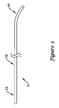
ここでガイドワイヤ1の斜視図である図5を参照する。ガイドワイヤは基端12及び先端11を備えたシャフト10を有する。本願に記載するガイドワイヤは、様々な手技において使用することができる。ガイドワイヤは、患者の脈管構造のような体内管腔内に挿入されるように賦形され、かつ構成することができる。次いで、カテーテルのような別の器具にガイドワイヤ上を進ませて、患者の脈管構造内の問題の部位まで到達させることができる。ガイドワイヤはまた、患者の脈管構造内の適所に配置されたカテーテルを通って進ませてもよい。加えて、ガイドワイヤは、バルーン、アテローム切除器具、又は血管内処置を行うために当業で知られている他の器具のような、ガイドワイヤの長さに沿って配置される器具を有することができる。ガイドワイヤはまた、ガイドワイヤの長さの全体又は一部に沿って延びる管腔を有し、これにより、他の器具又は要素による該管腔内の通過、及び/又は、ガイドワイヤの長さの全体又は一部を介した流体が流れるような連通を可能にしてもよい。
Reference is now made to FIG. 5, which is a perspective view of the
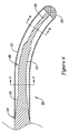
図6は、本発明のガイドワイヤの一実施形態の先端部の縦断面図を示す。シャフト20は管状部材21を備えることができる。シャフトはまた、第1テーパ領域23を有するコア部材22も備えることができる。管状部材21及びコア部材22は、例えば第1テーパ領域23に位置し得る接合部24において互いに取り付けることができる。コア部材22の少なくとも一部は、管状部材の管腔26内に配置することができる。
FIG. 6 shows a longitudinal sectional view of the distal end portion of one embodiment of the guide wire of the present invention. The
任意の広範かつ様々な取り付け技術及び/又は構造を用いて、管状部材21およびコア部材22、又はシャフト20に存在する任意の構造同士の取り付けを行うことができる。好適な取り付け技術のいくつかの例としては、溶接、はんだ付け、ろう付け、圧着、摩擦嵌合、接着、機械的かみ合わせなどが挙げられる。
Any of a wide variety of attachment techniques and / or structures can be used to attach the
一部の実施形態に好適であり得る溶接法のいくつかの例としては、レーザ溶接、抵抗溶接、TIG溶接、マイクロプラズマ溶接、電子ビーム溶接、摩擦溶接、イナーシャ溶接などが挙げられる。一部の用途に好適であり得るレーザ溶接装置は、米国カリフォルニア州モンロビア(Monrovia)に所在するユニテック・ミヤチ社(Unitek Miyachi)及び米国ミシガン州プリマス(Pl ymouth)に所在するロフィン−シナール社(Rofin-Sinar Incorporated)から市販されている。一部の用途に好適であり得る抵抗溶接装置は、米国カリフォルニア州カールスバッド(Carlsbad)に所在するパロマー・プロダクツ社(Palomar Products Incorporated) 及び米国カンザス州オラース(Olathe)に所在するポラリス・エレクトロニクス社(Polaris Electronics) から市販されている。一部の用途に好適であり得るTIG溶接装置は、米国カリフォルニア州ニューベリーパーク(Newbury Park)に所在するウェルドロジック社(Weldlogic Incorporated)から市販されている。一部の用途に好適であり得るマイクロプラズマ溶接装置は、米国テネシー州スマーナ(Smyrna)に所在するプロセス・ウェルディング・システムズ社(Process Welding Systems Incorporated)から市販されている。 Some examples of welding methods that may be suitable for some embodiments include laser welding, resistance welding, TIG welding, microplasma welding, electron beam welding, friction welding, inertia welding, and the like. Laser welding devices that may be suitable for some applications are Unitek Miyachi, located in Monrovia, Calif., And Rofin-Sinar, Inc., located in Plymouth, Michigan, USA. -Available from Sinar Incorporated. Resistance welding equipment that may be suitable for some applications are Palomar Products Incorporated, located in Carlsbad, California, and Polaris Electronics, Inc., located in Olathe, Kansas, USA ( Commercially available from Polaris Electronics). TIG welding equipment that may be suitable for some applications is commercially available from Weldlogic Incorporated located in Newbury Park, California. A microplasma welding apparatus that may be suitable for some applications is commercially available from Process Welding Systems Incorporated, Smyrna, Tennessee.
一部の実施形態においては、レーザ溶接又はプラズマ溶接を用いて取り付けを行うことができる。レーザ溶接では、必要な熱を供給するために光線を用いる。レーザ溶接は、レーザ光熱源の使用によって高い精度を得られるため、本発明が企図する工程において有用であり得る。器具の他の構成要素を取り付けるためにも、そのようなレーザ溶接を使用することができることも理解されよう。加えて、一部の実施形態において、レーザエネルギーは、ガイドワイヤの異なる構成要素又は構造を相互に取り付けるために、はんだ付け、又はろう付けなどを行うための熱源として使用することができる。また、レーザ光熱源の使用により相当な精度を提供することができるため、そのような接合技術のための熱源としてレーザを使用することは有益であり得る。そのような技術の1つの特定の例としては、レーザダイオードソルダリングが挙げられる。 In some embodiments, attachment can be performed using laser welding or plasma welding. Laser welding uses light to provide the necessary heat. Laser welding can be useful in the process contemplated by the present invention because high accuracy can be obtained through the use of a laser light source. It will also be appreciated that such laser welding can be used to attach other components of the instrument. In addition, in some embodiments, the laser energy can be used as a heat source for soldering, brazing, or the like to attach different components or structures of the guidewire together. It can also be beneficial to use a laser as a heat source for such a bonding technique, since the use of a laser photothermal source can provide considerable accuracy. One particular example of such a technique is laser diode soldering.
加えて、他のいくつかの実施形態の例において、取り付けは、機械的コネクタ又は機械的連結体の使用によって、かつ/又は、拡張可能な合金、例えばビスマス合金によって、達成し、かつ/又は、補助され得る。そのような拡張可能な材料を用いてガイドワイヤの異なる部分を相互接続するために使用することができる方法、技術及び構造のいくつかの例は、2003年2月26日に出願された米国特許出願第10/375,766号(米国特許出願公開第2004/0167441号明細書)に開示されている。同明細書の内容は、参照により本明細書の一部を構成する。異なる区域を相互接続するために使用することができるいくつかの方法及び構造は、米国特許第6,918,882号明細書、及び2002年2月28日に出願された米国特許出願第10/086,992号(米国特許出願公開第2003/0069521号明細書)に開示されている。これら米国特許及び米国特許出願明細書の内容は、参照により本明細書の一部を構成する。 In addition, in some other example embodiments, attachment is achieved by use of a mechanical connector or mechanical coupling and / or by an expandable alloy, such as a bismuth alloy, and / or Can be assisted. Some examples of methods, techniques and structures that can be used to interconnect different portions of a guidewire with such expandable materials are described in US Patents filed on Feb. 26, 2003. No. 10 / 375,766 (U.S. Patent Application Publication No. 2004/0167441). The contents of this specification constitute part of this specification by reference. Some methods and structures that can be used to interconnect different areas are described in US Pat. No. 6,918,882 and US patent application Ser. No. 10/90, filed Feb. 28, 2002. No. 086,992 (U.S. Patent Application Publication No. 2003/0069521). The contents of these US patents and US patent application specifications are hereby incorporated by reference.
図6に示すように、コア部材22は管腔26の全長にわたって延在することができる。あるいは、コア部材22は管腔26の一部に沿ってのみ延在してもよい。例えば、コア部材22は、接合部24までのみ延在していてもよく、あるいは管腔26を通って少なくともその全長の約25%、又は少なくとも約50%、又は少なくとも約75%以上、またはそれ以上にわたって延在していてもよい。コア部材が管腔26の一部のみを通って延在する場合、コア部材22の端にワイヤ延長部を取り付けることもできる(この構成については以下でより詳細に説明する)。
As shown in FIG. 6, the
加えて、管状部材21及びコア部材22は、コア部材22の外面の少なくとも一部と管状部材21の内面との間に空間又は間隙27が画定され得るように、寸法及び/又は形状を有するように形成されるか、又はその他の方法でそのように適合され、かつ/又は、構成され得る。例えば、管状部材21は、該管状部材内に配置されるコア部材22の外径より大きな内径を有することができる。従って、管状部材21は、管状部材21とコア部材22との間に空間又は間隙27が画定されるように、コア部材22又はその一部のまわりに配置され得る。一部の実施形態において、間隙又は空間27は、接合部24もしくは先端チップ25への取り付け部、又はそれら双方を除いて、管状部材21内に配置されるコア部材22のほぼ全長にわたって、開放された状態、又は器具1の他の構造によって充填されていない状態を保つ。
In addition, the
一部の実施形態において、間隙又は空間27は、コア部材22の外面と管状部材21の内面との間において、管状部材21の長さに沿って、管状部材21の全長の約50%以上、約75%以上、約90%以上、又は約95%以上の範囲に延在することができる。しかしながら、別の実施形態においては、コア部材22と管状部材21との間における他の複数の取り付け点が用いられてもよい。その結果として、これらの付加的な取り付け点によって分離され得る複数の間隙又は空間が形成され得る。前記取り付け点は、実際には、間隙又は空間27の一部を充填することができる。そのような複数の間隙又は空間は、それでも、合わせると、管状部材21の長さのかなりの部分に沿って、例えば上述したような全長に対する割合で延在し得る。
In some embodiments, the gap or
管状部材21はまた、コア部材22の異なる量の長さに沿って延在してもよい。例えば、管状部材21は、コア部材22の全長の約25%以下、約50%以下、約75%以下、約90%以下、又は約95%以下に沿って延在することができる。それゆえ、管状部材は、シャフト10に対して、ねじれ剛性又は押進可能な剛性(pushable rigidity) のような所望の特性を高めるように、又はそのような特性を付与するように作用することができるが、間隙又は空間27は、少なくとも間隙又は空間27に包囲されたコア部材22の部分が管腔26内において横方向に移動することを可能にすることができる。さらに別の実施形態においては、1つ以上のコイル、リボン、バンド、マーカ部材などのような1つ以上の他の構造を、間隙27の一部に配置して、これを充填してもよい。
接合部24に近接した管状部材21の外径は、接合部24の基端側のコア部材22の外径とほぼ同じとすることができる。管状部材21の外径は、その長さに沿ってほぼ一定であってもよい。コア部材22の外径も、接合部24の基端側においてほぼ一定であってもよい。接合部24の基端側のコア部材22の外径と、管状部材21の外径とがほぼ同一かつ一定である場合、ガイドワイヤの全長はほぼ一定の外径を有し得る。別の実施形態において、管状部材21の外径又は接合部24の基端側のコア部材の外径、又はそれら双方がテーパ状である場合には、ガイドワイヤはテーパ構成を有し得る(そのようなテーパについてはさらに以下で説明する)。
The outer diameter of the
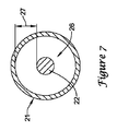
再度図6を参照すると、コア部材22は、中実円形断面を有することができる。コア部材22の断面はまた、円形、扁平形、楕円形、矩形、正方形、多角形など、又は他の同様の様々な断面形状を有することができる。あるいは、コア部材22の断面形状はその長さに沿って変化していてもよい。例えば、図7及び図8は、図6のガイドワイヤに沿った2つの長手方向位置における断面図を示す。これらの図面は、円形断面から扁平な又は矩形の断面に変化するコア部材22を示している。コア部材22の一部又は全体はまた、中空断面を有していてもよい。コア部材22の中空断面を有する部分は、基端領域から先端領域まで管腔を画定することができる。そのような管腔は、ガイドワイヤを介して別の器具を通過させることを可能にしたり、又はガイドワイヤの長さの全体又は一部に沿って流体が流れるような連通を可能にしたりすることができる。
Referring again to FIG. 6, the
図7及び図8に示すように、管状部材21の内面及び外面は円形断面を有することができる。これらの面はまた、円形、扁平形、楕円形、矩形、正方形、多角形などのような他の断面形状、又は他の同様の様々な断面形状を有することができる。あるいは、管状部材21の断面形状はその長さに沿って変化してもよく、また、管状部材31はその内面及び外面において異なる断面形状を有していてもよい。
As shown in FIGS. 7 and 8, the inner and outer surfaces of the
シャフト20はまた、その先端に配置された先端チップ25も備えることができる。先端チップ25は、任意の多様なチップ構造及び/又はアセンブリを備えることができ、非外傷性又は可撓性のような特定の特性をシャフト20の先端に付与するように構成され、かつ/又は、そのように適合され得る。先端チップ25は、所望される性能特性に応じて、様々な異なる材料から形成することができる。一部の実施形態において、先端チップ25は、シャフト20の先端上に非外傷性要素を提供するために、全体的又は部分的に丸味を帯びた構造を備えることができる。一部の実施形態において、先端チップ25は、シャフト20の先端に対して、溶接、はんだ付け、又はその他の取り付けを行い易い金属材料のような材料で形成することができる。例えば、一部の実施形態において、先端チップ25は、器具1の先端にはんだ付けによって配置されて非外傷性の丸味を帯びた部分を形成するはんだチップ又ははんだボールとすることができる。別の実施形態においては、先端チップ25は既製構造又は部分的に既製構造とすることができ、これは、後に、溶接、はんだ付け、ろう付け、圧着、摩擦嵌合、接着、機械的かみ合いなどの好適な取り付け技術を用いて器具の先端に取り付けられる。そのような先端チップ構造を形成するためには、はんだ付け、深絞り、ロール成形又は金属スタンピング、金属射出成形、及び鋳造などのような様々な異なる製法を用いることができる。
The
図5、図6及び図9に示す実施形態において、先端チップ25は、例えば管状部材(21,51)の先端もしくはコア部材22の先端あるいはそれら双方(図6に示したように)に、かつ/又は、シャフト20の先端もしくはその付近に位置する他の構造に取り付けられる、金属チップもしくははんだチップのような丸味を帯びた構造を備える。それゆえ、図示する実施形態においては、管状部材21及びコア部材22の双方は、先端チップ56まで、かつ/又は先端チップ56内へと延在しているが、上述したように、これはすべての実施形態において必須な構成ではない。加えて、リボン、コイル、マーカバンド、センタリングリングなどのような他の構成要素もまた、先端チップ又はシャフト20の他の部分の一部を構成していてもよく、あるいは先端チップ又はシャフト20の他の部分に隣接して配置されてもよい。一実施形態において、ワイヤ又はリボンは、コア部材22の先端に取り付けることができる。このワイヤ又はリボンは先端チップ25まで延在することができ、場合により、先端チップ25に取り付けることができる。ワイヤリボンは、円形、扁平形、楕円形、矩形、正方形、多角形などの断面形状、又は他の同様の様々な断面形状を有していてもよく、あるいは断面形状はリボンの長さに沿って変化していてもよい。
In the embodiment shown in FIGS. 5, 6 and 9, the
チップ構造はまた、管状部材21の管腔26内に配置され、かつ、コア部材22の少なくとも一部の周囲に配置された、螺旋コイル又はポリマーシースのような長尺状可撓性部材を備えることもできる。可撓性部材は螺旋コイルであってもよい。そのようなコイルは、器具の先端チップを補強するように機能することができ、かつ/又は、放射線不透過性マーカとして機能することができ、あるいはそれら両方の機能を果たすことができる。コイルは、中実断面を有し、かつ円形、楕円形、扁平形、リボン形状、もしくは他の好適な形状又はそれらの組み合わせを含む様々な断面形状のうち任意の形状を有することができるワイヤ又はリボンから形成されるか、又はそのようなワイヤ又はリボンを備えることができる。コイルは、金属、合金、プラスチック又は放射線不透過性物質を含む任意の他の好適な材料を含む様々な材料で形成することができ、それらの材料の多くについては上述した。使用可能な他の好適なチップの構成及び構造のいくつかの例は、米国特許第6,918,882号明細書、及び2002年2月28日に出願された米国特許出願第10/086,992号(特許出願公開第2003/0069521号明細書)に開示されている。これら米国特許及び特許出願明細書の内容は、参照により本明細書の一部を構成する。さらに、上述したようなコイル又は他の補強部材は、シャフトの可撓性が変化している領域の周囲に、その可撓性の変化を高めるために配置することができる。
The tip structure also includes an elongate flexible member, such as a helical coil or polymer sheath, disposed within the
ガイドワイヤはまた、その長さに沿って可撓性を変化させることもできる。ガイドワイヤは、患者の脈管構造内における蛇行した通路の通行を容易にするために、ガイドワイヤの基端部においてよりも、ガイドワイヤの先端部において、より可撓性を高くすることができる。可撓性の変化は、コア部材22の形状、断面積又は構成材料の変更、あるいは管状部材21の形状、断面積又は構成材料の変更、又はこれらの変更の任意の組み合わせによって生じさせることができる。
The guidewire can also vary in flexibility along its length. The guidewire may be more flexible at the distal end of the guidewire than at the proximal end of the guidewire to facilitate passage of tortuous passages within the patient's vasculature. . The change in flexibility can be caused by a change in the shape, cross-sectional area or constituent material of the
従って、コア部材及び/又は管状部材21/22は、1つ以上のテーパ又はテーパ領域を備えることができる。テーパ領域は、直線的にテーパが付けられていてもよく、曲線状にテーパが付けられていてもよく、均一にテーパが付けられていてもよく、不均一にテーパが付けられていてもよく、又は階段状にテーパが付けられていてもよい。このようなテーパの角度は、所望される可撓性に応じて変更することができる。テーパの長さは、剛性/可撓性がより緩やかに移行するように(長さをより長くするように)、又は剛性/可撓性がより急激に移行するように(長さをより短くするように)、選択することができる。シャフト20ならびに/又はコア及び/もしくは管状部材21/22のほぼ任意の部分にテーパを付けることができ、テーパは基端方向又は先端方向のいずれに向かって付けられてもよい。コア及び/又は管状部材21/22は、外径が小さくなる1つ以上の部分と、外径がほぼ一定のままである1つ以上の部分とを備えることができる。径減少部分及び一定径部分の数、配置、寸法、及び長さは、可撓性及びトルク伝達性のような所望の特性を達成するために変更することができる。
Accordingly, the core member and / or the
例えば、図6に示す実施形態において、コア部材22は、基端領域29においてよりも、先端領域28において、より高い可撓性を有することができる。この可撓性における変化は、例えば、コア部材22が先端側に延びるにつれて、コア部材22の長さに沿って断面積を減少させることによって達成することができる。一部の実施形態の例において、コア部材22の外径は、約0.005〜0.04インチ(約0.127〜1.016mm)の範囲とすることができる。しかしながら、本発明の趣旨から逸脱することなく、他の寸法を用いてもよいことは理解されたい。
For example, in the embodiment shown in FIG. 6, the
任意のテーパ部分及び/又は一定径部分を含むコア部材22の形状は、例えば、センタレス研削法、スタンピング法などの多くの様々な技術のうち任意の技術を用いて形成することができる。センタレス研削技術は、接合部の過度の研削を避けるために、センサ(例えば、光学式/反射式センサ、磁気センサ)を使用したインデキシングシステムを用いることができる。さらに、センタレス研削技術は、研削加工中に構造ワイヤを引っ掛けないように良好に賦形され、仕上げられたCBN又はダイヤモンド砥粒研削ホイールを用いてもよい。一部の実施形態において、センタレス研削は、ロイヤルマスター社(Royal Master)のHI−ACセンタレス研削機を使用して行うことができる。好適な研削法のいくつかの例は、2003年1月17日に出願された米国特許出願第10/346,698号(特許出願公開第2004/0142643号明細書)に開示されており、同明細書の内容は、参照により本明細書の一部を構成する。
The shape of the
また、一部の実施形態において、コア部材22の一部は、例えば、所望の可撓性を提供するために、又は他の構造に対する取り付け点を提供するために、平坦化されてもよい。例えば、コア部材22は、図8に示すように、先端領域28において平坦部分を備えることができる。例えば、先端領域28の最先端の約0.05〜1インチ(約1.27mm〜2.54cm)の部分は、ほぼ平行な対向する表面を画定し、かつ約0.0005〜0.003インチ(約12.7〜76.2μm)の範囲の厚さを有するように平坦化することができる。
Also, in some embodiments, a portion of the
管状部材21はまた、1つ以上のテーパ又はテーパ領域と、1つ以上の一定径区域とを備えてもよいし、又は一定の内径及び/又は外径を備えていてもよい。任意のテーパ及び/又は一定径部分は、例えば所望の可撓性/剛性を達成するために、基端方向又は先端方向のいずれにも延びることができる。テーパ及び/又は任意の一定径区域は、管状部材21の外径、内径、及び/又は壁厚における変化及び/又は非一貫性により生じさせることができる。テーパ領域は、直線的にテーパが付けられていてもよく、曲線状にテーパが付けられていてもよく、均一にテーパが付けられていてもよく、不均一にテーパが付けられていてもよく、又は階段状にテーパが付けられていてもよい。このようなテーパの角度は、所望される可撓性に応じて変更することができる。テーパの長さは、剛性/可撓性がより緩やかに移行するように(長さをより長くするように)、又は剛性/可撓性がより急激に移行するように(長さをより短くするように)、選択することができる。
一部の実施形態において、管状部材21は管腔26を画定する内径を有することができる。内径の寸法は、約0.01〜0.06インチ(約0.254〜1.524mm)の範囲内であり、一部の実施形態においては、約0.02〜0.035インチ(約0.508〜0.889mm)の範囲内である。加えて、一部の実施形態において、管状部材21は、約0.015〜0.07インチ(約0.381〜1.778mm)の範囲であり、一部の実施形態では約0.02〜0.04インチ(約0.508〜1.016mm)の範囲である外径を有することができる。しかしながら、本願において提供されたこれら及び他の寸法は実施形態の例として示すに過ぎず、別の実施形態においては、管状部材21及び医療器具の他の要素の内径及び外径の寸法は、器具に所望される特性及び機能に応じて、所与の寸法から大きく変更してもよいことは理解されたい。
In some embodiments, the
管状部材21はまた、所望のレベルの剛性、トルク伝達性、可撓性、及び/又は他の特性を実現するように、他の構造を備えるか、又はその他の方法でそのように構成され、かつ/又は、そのように適合され得る。管状部材21に所望される剛性、トルク伝達性、横方向の可撓性、曲げ性、又は他の同様の特性は、管状部材21に使用されるか、又は組み込まれ得る特定の構造によって、付与され、高められ、又は改変することができる。よって、理解されるように、例えば、可撓性が基端に比べて先端でより高くなるように、又はその反対となるように、管状部材の可撓性をその長さに沿って変化させることができる。しかしながら、一部の実施形態において、管状部材はその全長に沿ってほぼ一定の可撓性を有していてもよい。
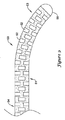
付加的な可撓性を付与する1つの手法は、管状部材(例えば管状部材21)の一部から材料を選択的に除去することである。例えば、図9に関連して、管状部材51は、管状部材51の一部に、又は全長に沿って形成された溝、切り欠き、スリット、スロットなどのような1つ以上又は複数の開口52を含む薄壁管状構造を備えることができる。開口52は、ほぼ任意の公知の方法で形成することができる。例えば、開口52は、マイクロマシニング加工、ソー切断、レーザ切断、研削、フライス加工、鋳造、成形、化学エッチングもしくは化学処理のような方法や、他の公知の方法などによって形成することができる。一部のそのような実施形態において、補強部材52の構造は、開口52を形成するために、管の一部を切断及び/又は除去することによって形成される。
One approach to impart additional flexibility is to selectively remove material from a portion of the tubular member (eg, tubular member 21). For example, with reference to FIG. 9, the
一部の実施形態においては、開口52を介して管腔(例えば管腔26)と管状部材51の外部とが連通するように、開口52は管状部材51の本体壁を完全に貫通していてもよい。一部の実施形態においては、開口52は、管状部材51の内面又は外面のいずれかにおいて管状部材51の本体壁内に部分的にのみ延びていてもよい。別の実施形態では、管状部材51の本体壁を完全に貫通する開口52と部分的に貫通する開口52との組み合わせを備えていてもよい。開口52の形状及び寸法は、例えば、所望の特性を実現するように変更することができる。例えば、開口52の形状は、正方形、円形、矩形、球形、楕円形、多角形、長尺状、不規則形、螺旋形(ピッチは変化していてもよいし、変化していなくてもよい)、又は他の好適な手段などのようなほぼ任意の適切な形状を含むように変更することができ、丸味を帯びた縁又は角ばった縁を有するようにしてもよく、長さ及び幅などが変化するようにしてもよい。
In some embodiments, the
一部の実施形態においては、いくつかの隣接する開口52は、それらの開口が管状部材51の周面において互いに重なり合う部分を備えるように形成することができる。別の実施形態においては、いくつかの隣接する開口52は、必ずしも互いに重なり合わないが、所望の程度及び/又は方向の横方向の可撓性を提供するパターンにて配置されるように、配置することができる。例えば、開口52は、管状部材51の周面において対向する側面上にほぼ均等に配置される、又は管状部材51の長さに沿って均等に離間されるといったように、対称的なパターンに配列することができる。
In some embodiments, a number of
理解され得るように、開口52の間隔、配置及び/又は配向は、所望の特性を達成するために変更することができる。例えば、管状部材51の長さに沿った開口52の数、近接度(互いに対する)、密集度、寸法、形状及び/又は深さは、所望される特性に応じて、段階的に、又は一貫して変化させることができる。例えば、管状部材51の一端の付近における開口52の数又は互いに対する近接度は多く又は高く、管状部材51の他端の付近における開口52の数又は互いに対する近接度は比較的少なく又は低くされていてもよく、あるいはその逆であってもよい。一部の実施形態において、管状部材51の先端領域53では、開口52の密集度がより高くてもよく、一方、管状部材51の基端領域54では、開口の密集度はより低くてもよく、あるいは開口52を全く有さなくてもよい。そのため、先端領域53は、基端領域54に比べてより高い横方向の可撓性を有することができる。管状部材51の長さに沿った開口52の寸法、形状及び/又は深さにおける同様の変化を用いて、管状部材51の長さに沿って所望の可撓性差を達成することができることは理解されたい。
As can be appreciated, the spacing, arrangement and / or orientation of the
図9に示した実施形態において、開口52は、管状部材51の長さに沿ってほぼ均一なパターンで配置されており、開口密集度は管状部材51の基端部においてよりもその先端部において高くなっている。この実施形態において、開口52は長さ及び幅を有することができ、開口の長さは管状部材51の長手方向軸線にほぼ直交して延びている。換言すると、開口52は、本体51の長手方向軸線を中心として半径方向に延びるそれらの開口の長さに沿って延びる長軸を有することができ、該長軸は、管状本体51の長手方向軸線にほぼ直交する。
In the embodiment shown in FIG. 9, the
加えて、図示する実施形態においては、開口52が2つの開口からなるグループをなすように形成されており、グループの2つの開口52の各々は、管状部材51の長さに沿った同様の長手方向地点であるが、管状部材の周面において管状部材の対向する側面上に配置されている。隣接した対の開口52は、90度、又は90度未満、例えば80度、85度又は89度回転され得る。しかしながら、別の実施形態においては、管状部材51の長さに沿った所望の特性を達成するために、開口の配置を変更することができることは理解されたい。例えば、対ではなく、1つの開口のみを、又は3つ以上の開口を器具の長さに沿った特定の場所に配置することができる。加えて、開口の長軸は、管状部材51の長手方向軸線に対して必ずしも直交する必要はなく、異なる角度で配置されていてもよい。
In addition, in the illustrated embodiment, the
まとめると、本説明は、開口52の配置、数及び構成における変化は、本発明の範囲から逸脱することなく変化させ得ることを示している。例えば、管状本体は開口52を全く有さなくてもよい。切り欠き又はスロットのような、管状本体に形成された開口の配置のいくつかの付加的な例は、米国特許第6,428,489号明細書及び同第6,579,246号明細書に開示されている。なお、これら米国特許明細書の内容は、参照により本明細書の一部を構成する。また、医療器具で使用するための管状本体に形成された切り欠き又はスロットの配置のいくつかの付加的な例は、2003年2月28日に出願された米国特許出願第10/375,493号(特許出願公開第2004/0167437号明細書)に開示されており、その内容は、参照により本明細書の一部を構成する。
In summary, the present description shows that changes in the arrangement, number and configuration of the
管状部材21の可撓性特性の実現は、他の方法、例えば管状部材21及び/又はコア部材22の特定の部分に材料及び/又は1つ以上の補強部材を追加することによって為すこともできる。管状部材21又はコア部材22に可撓性を付与する別の一方法は、これらの部材に螺旋状の切り込みを形成することである。螺旋状の切り込みは、管状部材21の壁の全厚を貫通して、又は壁の一部のみを通って延在することができる。螺旋状の切り込みはまた、ピッチを有することができ、ピッチは、管状部材の長さに沿って一定であってよく、あるいは変化していてもよい。例えば、螺旋状の切り込みのピッチは、部材の基端と比較して部材の先端において、螺旋状の切り込みの隣接する切り込み同士を互いにより接近させるように、又はその反対に変化させることができる。
Realization of the flexible properties of the
当業者らであれば、コア部材22及び管状部材21の材料、構造及び寸法は、完成品であるガイドワイヤに所望される特性及び機能によって主として決定され、広範な材料、構造及び寸法のうち任意のものを用い得ることは理解されよう。なお、本明細書で説明した可撓性管状構造のいずれも本明細書に説明した医療器具の実施形態のうち任意のものに組み込むことができる。
For those skilled in the art, the material, structure and dimensions of the
例えば、管状部材21及びコア部材22は、器具1に所望される特性に応じて、使用に適した任意の材料から形成することができる。好適な材料のいくつかの例としては、金属、合金、ポリマー、複合材などや、それらの組み合わせもしくは混合物が挙げられる。好適な金属及び合金の一部の例としては、304V、304L及び316Lステンレス鋼のようなステンレス鋼、線形弾性又は超弾性(すなわち偽弾性)ニチノールのようなニッケル−チタン合金を含む合金、ニッケル−クロム合金、ニッケル−クロム−鉄合金、コバルト合金、タングステン又はタングステン合金、MP35−N(Ni約35%、Co約35%、Cr約20%、Mo約9.75%、Fe約1%以下、Ti約1%以下、C約0.25%以下、Mn約0.15%以下、及びSi約0.15%以下の組成を有する)、ハステロイ、モネル400、インコネル625など、もしくは他の好適な材料、又はそれらの組み合わせもしくは合金が挙げられる。一部の実施形態においては、溶接、はんだ付け、ろう付け、圧着、摩擦嵌合、接着などのような金属接合技術に適した金属又は合金を使用することが望ましい。使用される特定の材料はまた、ある程度は、所望の可撓性要件又は他の所望の特性に基づいて選択され得る。
For example, the
一部の実施形態において、コア部材22及び管状部材21は同一の材料から製造されてもよい。あるいは、一部の実施形態においては、コア部材22及び管状部材21は、異なる材料から製造されてもよく、あるいは、コア部材22及び管状部材21がそれぞれ、異なる材料から形成された複数の部分又は区域を備えていてもよい。シャフト(10,20)の異なる部分を構成するために使用される材料は、シャフト(10,20)の異なる部分に、変化する特性、例えば可撓性及び剛性を付与するように選択され得る。
In some embodiments, the
例えば、一部の実施形態において、コア部材22は、ステンレス鋼線又はインコネルのような比較的堅い材料を含有するか、又はそのような材料から形成することができる。あるいは、コア部材22は、ニッケル−チタン合金、ニッケル−クロム合金、ニッケル−クロム−鉄合金、コバルト合金又は他の好適な材料のような金属もしくは合金を含有するか、又はそのような金属もしくは合金から形成することができる。多数の実施形態において、コア部材22を構成するために使用される材料は、例えば、押圧性及び/又はトルク伝達性を得るために、比較的堅いものを選択することができる。
For example, in some embodiments, the
一部の実施形態において、管状部材21は、超弾性特性及び/又は形状記憶特性を示す材料のような比較的可撓性の高い材料を含むか、又はそのような材料から形成することができる。例えば、管状部材21は、少なくとも部分的に、特定の条件下で形状記憶特性及び超弾性特性の双方を示すことができる合金(例えばニチノール又は本願に記載した他の形状記憶/超弾性合金)で形成することができる。
In some embodiments, the
いくつかの特定の実施形態において、管状部材21は、形状記憶特性及び超弾性特性の双方を示すことができる材料(例えばニチノールのような合金など)を含み、コア部材22はステンレス鋼線を備えることができる。ステンレス鋼線が器具の長さに沿って良好に力を伝達する一方で、管状部材21はコア部材22の先端部に付加的な支持を提供することができる。超弾性/形状記憶材料からなる管状部材21は、器具の先端部に、幾分の付加的な弾性を提供することができる。
In some specific embodiments, the
先に述べたように、一部の材料、特に一部の合金は、使用温度によって影響を受ける形状記憶特性及び/又は超弾性特性を有する。上記本文において説明したように、ニチノールのような形状記憶特性及び/又は超弾性特性を備えた合金又は他の材料は、Af温度、As温度、As温度、Mf温度、及びMs温度を有することができる。これらの臨界温度と使用温度との関係は、材料の特性の決定因となり得る。例えば、使用温度(本願ではTmと称される)がAf温度より高い場合、材料は、応力を加えられると、超弾性特性を示すことができる。TmがAs温度より高いが、Af温度より低い場合には、材料は、該材料が変形されると幾分の超弾性特性を示すことができ、その後に材料がAf温度より高いTmに加熱される場合には、該材料は形状記憶特性を示すことができ、その元の形状及び寸法に復帰することができる。さらにTmがAs温度及びAf温度より低い場合には、前記材料は、応力下におかれると、完全にマルテンサイトになるか、又は完全なマルテンサイト相を形成することができ、TmがAs温度及びAf温度より低く維持される限り、前記材料は超弾性特性を示し得ない(しかしながら、その後にTmがAs温度及び/又はAf温度より高く上昇させられた場合には、前記材料は形状記憶特性を示し得る)。この材料は、変形され、該材料が続いて熱のような促進要因に晒されない場合には、その変形した形状を維持することができる。別の例では、TmがMs及び/又はMf温度より低い場合には、応力を加えられていない材料は、部分的に又は全体的にマルテンサイト相であり得る。そのようなシナリオにおいて、前記材料は、変形されると、ほぼ変形されたままとなり得る。ここでも、そのような材料は、後にAs温度及び/又はAf温度より高い温度に加熱された場合には、形状記憶特性を示すことができる。 As previously mentioned, some materials, particularly some alloys, have shape memory and / or superelastic properties that are affected by the temperature of use. As described in the above text, the shape memory properties and / or alloys or other materials with superelastic properties, such as Nitinol, A f temperature, A s temperature, A s temperature, M f temperature, and M s Can have a temperature. The relationship between these critical temperatures and service temperatures can be a determinant of material properties. For example, if the operating temperature (referred to as the T m in the present application) is higher than the A f temperature, the material, when added stress may exhibit superelastic properties. Although T m is higher than the A s temperature, is lower than the A f temperature, the material can exhibit somewhat superelastic properties when the material is deformed, it is higher than the A f temperature then material When heated to Tm , the material can exhibit shape memory properties and can return to its original shape and dimensions. If more T m is less than the A s temperature and A f temperature, the material, when placed under stress, it is possible to form a fully or becomes martensite, or full martensite phase, T as long as m is kept below a s temperature and a f temperature, the material is not shown superelastic properties (however, if thereafter T m have been raised above the a s temperature and / or the a f temperature The material may exhibit shape memory properties). This material can be deformed and maintain its deformed shape if the material is not subsequently exposed to a facilitating factor such as heat. In another example, if T m is below the M s and / or M f temperature, the unstressed material may be partially or wholly in the martensitic phase. In such a scenario, the material can remain substantially deformed when deformed. Again, such materials, when heated to a temperature above A s temperature and / or the A f temperature after, can exhibit shape memory characteristics.
本発明のいくつかの実施形態において、管状部材21は異なる領域を有し得る。異なる領域は管状部材21に沿った異なる長手方向位置に位置し得る。これらの領域は異なる材料もしくは合金、又は同一の材料もしくは合金を含み得る。該領域は、本願に記載したような臨界温度Mf、Ms、As及びAfを有する材料を含むことができる。
In some embodiments of the present invention, the
いくつかの実施形態において、前記領域のうちの一部(変形可能領域と称することができる)は、Tmより高いMs温度及びMf温度を有することができる(重ねて述べるが、Tmは器具が使用され得る温度(又は温度範囲)である)。一方、別の領域(弾性領域と称することができる)は、Tmより低いAs温度と、Tmより高いままであるAf温度とを有することができる。このような場合、温度がTmに、又はTm範囲内に維持される限り、変形可能領域を変形させることができ、該変形可能領域は変形した形状をほぼ維持することができる。一方、弾性領域は変形させることができ、少なくとも部分的にそれらの元の形状に復帰し得る。いくつかの実施形態において、変形可能領域のAs温度がTmより高く、かつMf温度及び/又はMs温度はTmより低く、かつ弾性領域が上述の通りである場合には、同様の特性が生じ得る。この場合、同様の物理的性質が生じ得る(変形可能領域はそれらの変形した形状をほぼ維持し、弾性領域は少なくとも部分的な弾性特性を有する)が、変形可能領域は、変形させられると、応力誘起マルテンサイトを形成し得る。 In some embodiments, some of the regions (which can be referred to as deformable regions) can have M s and M f temperatures that are higher than T m (again, T m Is the temperature (or temperature range) at which the instrument can be used). On the other hand, (which may be referred to as elastic region) different regions can have a low A s temperature than T m, and A f temperature remains above the T m. In this case, the temperature T m, or as long as is maintained in the T m range, it is possible to deform the deformable region, the deformable region may be substantially maintain the shape deformed. On the other hand, the elastic regions can be deformed and at least partially return to their original shape. In some embodiments, when A s temperature of the deformable region is higher than T m, and M f temperature and / or the M s temperature is lower than T m, and the elastic regions are as described above, as well The following characteristics can occur. In this case, similar physical properties can occur (deformable regions substantially maintain their deformed shape and elastic regions have at least partial elastic properties), but when deformable regions are deformed, Stress-induced martensite can be formed.
他の一部の実施形態において、変形可能領域の特性及び構成材料は、上述したものと同一の特性及び材料を有することができる。一方で、弾性領域は上述したものと同様の又は同一の構造を有することができるが、Tmより低いAs温度及びAf温度の双方を有し得る。そのような場合、弾性領域はより顕著な弾性特性を有することができる。 In some other embodiments, the properties and constituent materials of the deformable region can have the same properties and materials as described above. On the other hand, the elastic region may have a similar or identical structure to those described above, may have both lower than the T m A s temperature and A f temperatures. In such cases, the elastic region can have more pronounced elastic properties.
別の実施形態において、変形可能領域においてAf温度はTmをわずかに下回り得る一方で、弾性領域においてAf温度はTmをはるかに下回り得る。そのような例における領域はすべて幾分の弾性特性を有するが、変形可能領域は弾性領域よりも弾性が劣るであろう。例として、変形可能領域のAf温度はTmの5℃以内にあり、弾性領域のAf温度はTmより少なくとも10℃、15℃又は20℃低くなり得る。 In another embodiment, A f temperature in the deformable zone while obtaining slightly below the T m, A f temperature in the elastic region may well below T m. All the regions in such an example will have some elastic properties, but the deformable region will be less elastic than the elastic region. By way of example, the A f temperature of the deformable region is within 5 ° C. of T m and the A f temperature of the elastic region can be at least 10 ° C., 15 ° C. or 20 ° C. below T m .
本願における実施形態のいずれにおいても、Tmは該して、典型的な医療器具が使用され得る特定の使用温度又は温度範囲であり得る。あるいは、Tmは、正常なヒト体温(37℃)、又は40℃、42℃、45℃、50℃もしくは55℃とすることができる。もしくは、Tmは、上記温度のいずれかの±5℃又は±10℃の温度範囲とすることができる。Tmによって表わされ得る他の温度範囲は、10℃〜37℃、10℃〜40℃、10℃〜42℃、10℃〜45℃、10℃〜50℃、10℃〜55℃、15℃〜37℃、15℃〜40℃、15℃〜42℃、15℃〜45℃、15℃〜50℃、15℃〜55℃、27℃〜32℃、27℃〜37℃、27℃〜40℃、27℃〜42℃、27℃〜45℃、27℃〜50℃、27℃〜55℃、32℃〜37℃、32℃〜40℃、32℃〜42℃、32℃〜45℃、32℃〜50℃、32℃〜55℃、37℃〜40℃、37℃〜42℃、37℃〜45℃、37℃〜50℃、37℃〜55℃、40℃〜42℃、40℃〜45℃、40℃〜50℃及び40℃〜55℃であり得る。 In any of the embodiments herein, T m can thus be a specific use temperature or temperature range in which a typical medical device can be used. Alternatively, T m can be normal human body temperature (37 ° C.) or 40 ° C., 42 ° C., 45 ° C., 50 ° C. or 55 ° C. Alternatively, T m can be within the temperature range of ± 5 ° C. or ± 10 ° C. of any of the above temperatures. Other temperature ranges that may be represented by T m are 10 ° C. to 37 ° C., 10 ° C. to 40 ° C., 10 ° C. to 42 ° C., 10 ° C. to 45 ° C., 10 ° C. to 50 ° C., 10 ° C. to 55 ° C., 15 C-37C, 15C-40C, 15C-42C, 15C-45C, 15C-50C, 15C-55C, 27C-32C, 27C-37C, 27C- 40 ° C, 27 ° C to 42 ° C, 27 ° C to 45 ° C, 27 ° C to 50 ° C, 27 ° C to 55 ° C, 32 ° C to 37 ° C, 32 ° C to 40 ° C, 32 ° C to 42 ° C, 32 ° C to 45 ° C 32 ° C to 50 ° C, 32 ° C to 55 ° C, 37 ° C to 40 ° C, 37 ° C to 42 ° C, 37 ° C to 45 ° C, 37 ° C to 50 ° C, 37 ° C to 55 ° C, 40 ° C to 42 ° C, 40 ° C It can be from 0C to 45C, from 40C to 50C and from 40C to 55C.
本願に記載した実施形態のいずれにおいても、異なる領域は異なる材料から形成することができ、あるいは異なる領域は上述した異なる特性を有するように処理されたほぼ同一の材料から形成することもできる。例えば、前記領域は、異なる領域では異なって処理されているほぼ同一の合金(例えばニチノール又は本願で述べた他の形状記憶合金及び/又は超弾性合金)を含むことができる。あるいは、前記領域は、異なる合金(例えばニチノール又は本願に列記した他の好適な合金のうち、異なる合金)を含むことができる。変形可能領域は、管状部材21の先端、先端部、中間部、基端部又はそれらの任意の組み合わせに位置し得る。1つ以上の変形可能領域及び弾性領域が存在してもよく、例えば、1つ、2つ、3つ、4つ、5つ、又は6つの変形可能領域及び/又は1つ、2つ、3つ、4つ、5つ又は6つの弾性領域が存在し得る。変形可能領域は、製造業者又は操作者が、医療器具を特定の用途及び患者の解剖学的構造に適合させるために、管状部材の形状を変更することを可能にすることができる。例として、変形可能領域は、患者の脈管構造の特に急な湾曲部に対応する位置において医療器具に沿って形成することができる。別の例として、医療器具の先端は患者の脈管構造内において蛇行した通路の通行を容易にするように賦形することができる。
In any of the embodiments described herein, the different regions can be formed from different materials, or the different regions can be formed from substantially the same material that has been processed to have the different characteristics described above. For example, the regions can include substantially the same alloy (eg, nitinol or other shape memory alloys and / or superelastic alloys described herein) that are treated differently in different regions. Alternatively, the region can include a different alloy (eg, a different alloy of Nitinol or other suitable alloys listed herein). The deformable region may be located at the distal end, distal end portion, intermediate portion, proximal end portion of the
第1変形可能領域及び第1弾性領域のみの間の関係について上述したが、他の任意の変形可能領域及び弾性領域が、Tmと第1変形可能領域及び第1弾性領域との関係と同様の関係を有し得る。例えば、第1変形可能領域がTmより高いAf温度を有し、かつ第1弾性領域はTmより低いAf温度を有する場合、第2変形可能領域もTmより高いAf温度を有することができ、かつ第2弾性領域もTmより低いAf温度を有することができる。2つ以上の変形領域及び/又は2つ以上の弾性領域を備えた実施形態においては、変形可能領域同士が互いに異なっていてもよく、弾性領域同士が互いに異なっていてもよい。弾性領域の各々は、個々に、本明細書に記載した任意の特性を有することができ、変形可能領域の各々は、個々に、本明細書に記載した任意の特性を有することができる。 Although the relationship between the first deformable region and the first elastic region only has been described above, other arbitrary deformable regions and elastic regions are the same as the relationship between Tm and the first deformable region and the first elastic region. The relationship may be For example, if the first deformable region has an A f temperature higher than T m and the first elastic region has an A f temperature lower than T m , the second deformable region also has an A f temperature higher than T m. And the second elastic region can also have an Af temperature lower than Tm . In the embodiment including two or more deformation regions and / or two or more elastic regions, the deformable regions may be different from each other, and the elastic regions may be different from each other. Each of the elastic regions can individually have any of the properties described herein, and each of the deformable regions can individually have any of the properties described herein.
別の実施形態例において、上記の実施形態のいずれかの弾性領域は、本願に記載する変形可能領域のいずれかと組み合わされて、線形弾性とすることができる。弾性領域の材料は、特定条件下において形状記憶特性及び/又は超弾性特性を有し得る材料とすることができるが、線形弾性となるように処理することができる。あるいは、弾性領域の材料は、特性的に線形弾性材料である材料としてもよい。別の実施形態において、本願に記載した変形可能領域のいずれも、医療器具の使用温度の範囲内において形状記憶特性を有することができる。これは、これらの領域が、使用温度(Tm)の範囲の上限付近の温度に晒されると、初期の形状及び構成に復帰することを可能にするが、この温度範囲(Tm)の下限では変形したままとなる。 In another example embodiment, the elastic region of any of the above embodiments can be combined with any of the deformable regions described herein to be linear elastic. The material in the elastic region can be a material that can have shape memory and / or superelastic properties under certain conditions, but can be processed to be linearly elastic. Alternatively, the material in the elastic region may be a material that is characteristically a linear elastic material. In another embodiment, any of the deformable regions described herein can have shape memory characteristics within the operating temperature range of the medical device. This allows these regions to return to their initial shape and configuration when exposed to temperatures near the upper limit of the operating temperature (T m ) range, but the lower limit of this temperature range (T m ). Then it remains deformed.
弾性領域及び変形可能領域の長さは変更することができる。例えば、医療器具の先端の変形可能領域は、0.1インチ〜7インチ(2.54mm〜17.78cm)の長さとすることができ、例えば、変形可能領域は、0.1インチ、0.2インチ、0.25インチ、0.3インチ、0.4インチ、0.5インチ、0.75インチ、1インチ、1.25インチ、1.5インチ、1.75インチ、2インチ、2.5インチ、3インチ、3.5インチ、4インチ、5インチ、6インチ又は7インチ(2.54mm、5.08mm、6.35mm、7.62mm、1.016cm、1.27cm、1.905cm、2.54cm、3.175cm、3.81cm、4.445cm、5.08cm、6.35cm、7.62cm、8.89cm、10.16cm、12.7cm、15.24cm、17.78cm)の長さとすることができる。中間部分に位置する変形可能領域は、同一の長さとしてもよい。 The length of the elastic region and the deformable region can be changed. For example, the deformable region at the tip of the medical device can be 0.1 inches to 7 inches (2.54 mm to 17.78 cm) long, for example, the deformable region can be 0.1 inches,. 2 inch, 0.25 inch, 0.3 inch, 0.4 inch, 0.5 inch, 0.75 inch, 1 inch, 1.25 inch, 1.5 inch, 1.75 inch, 2 inch, 2 inch .5 inch, 3 inch, 3.5 inch, 4 inch, 5 inch, 6 inch or 7 inch (2.54 mm, 5.08 mm, 6.35 mm, 7.62 mm, 1.016 cm, 1.27 cm; 905cm, 2.54cm, 3.175cm, 3.81cm, 4.445cm, 5.08cm, 6.35cm, 7.62cm, 8.89cm, 10.16cm, 12.7cm, 15.24cm, 17.78c ) Of can be the length. The deformable regions located in the middle part may have the same length.
一般に、図5、図6及び図9に示したガイドワイヤに関して上述した管状部材は、他の長尺状医療器具にも適用することができる。他のそのような医療器具は、一般に長尺状管状構造を組み込むことができる任意の医療器具(例えばカテーテル)とすることができる。 In general, the tubular members described above with respect to the guidewires shown in FIGS. 5, 6 and 9 can be applied to other elongated medical devices. Other such medical devices can be any medical device (eg, a catheter) that can generally incorporate an elongated tubular structure.
ここで、図10を参照すると、カテーテルシャフト60の一実施形態が斜視図にて示されている。カテーテルシャフト60は、基端部64及び先端部62と、これらの間に位置する中間部分とを有する管状部材61を備える。管状部材61は先端63も有し、かつ管状部材61は管腔69を画定する。一実施形態において、管状部材61は、ガイドワイヤに関して上述した管状部材21と同様の構造及び特性を有し得る。具体的には、管状部材21の可撓性を変化させるための形状及び可能な構造を、管状部材61においても使用することができる。さらに、カテーテルシャフトの先端63は、患者の体内管との外傷性の相互作用を防止するために、丸味を帯びた、かつ/又は、軟らかな、かつ/又は、より可撓性の高い部分を有することができる。
Referring now to FIG. 10, one embodiment of the catheter shaft 60 is shown in a perspective view. The catheter shaft 60 includes a tubular member 61 having a proximal end portion 64 and a
管状部材61が本明細書に記載した管状構造の任意のものを備えることができることについても企図している。管状部材61はまた、本明細書に記載した変形可能領域及び弾性領域に類似する変形可能領域及び弾性領域を有してもよい。例えば、変形可能領域及び弾性領域の数、物理的性質及び構成は、管状部材21に関して上述したものに類似していてもよい。
It is also contemplated that the tubular member 61 can comprise any of the tubular structures described herein. Tubular member 61 may also have deformable and elastic regions similar to the deformable and elastic regions described herein. For example, the number, physical properties and configuration of the deformable and elastic regions may be similar to those described above with respect to the
本明細書に記載したカテーテルシャフト又はガイドワイヤの一部又は全体は、場合により、放射線不透過性材料によってドープされていてもよいし、被覆されていてもよいし、めっきされていてもよいし、あるいは放射線不透過性材料から形成されていてもよいし、又はその他の方法で放射線不透過性材料を含有していてもよい。放射線不透過性材料とは、医学的処置の間に、蛍光透視スクリーン上又は別の撮像技術において比較的明るい像を生成することができる材料であると理解される。この比較的明るい像は、器具の使用者が器具の位置を判定しやすくする。放射線不透過性材料のいくつかの例としては、金、白金、パラジウム、タンタル、タングステン合金、放射線不透過性充填材が充填されたポリマー材料など、又はそれらの組み合わせもしくは合金を挙げることができるが、これらに限定されるものではない。 Part or all of the catheter shaft or guidewire described herein may optionally be doped, coated, or plated with a radiopaque material. Alternatively, it may be formed from a radiopaque material, or may contain a radiopaque material by other methods. A radiopaque material is understood to be a material capable of producing a relatively bright image on a fluoroscopic screen or in another imaging technique during a medical procedure. This relatively bright image makes it easier for the user of the instrument to determine the position of the instrument. Some examples of radiopaque materials can include gold, platinum, palladium, tantalum, tungsten alloys, polymeric materials filled with radiopaque fillers, or combinations or alloys thereof. However, it is not limited to these.
加えて、いくつかの実例において、本願の器具には一定のMRI適合性を付与することができる。例えば、核磁気共鳴映像法(MRI)装置との適合性を高めるために、ガイドワイヤ又はカテーテルシャフトの全体又は一部は、一定のMRI適合性を与えるように製造することができる。例えば、カテーテルシャフト又はガイドワイヤの全体又は一部は、MRI画像診断の間に、画像を実質的に歪めず、実質的なアーチファクト(アーチファクトとは画像中の実際とは異なる像である)を形成しない材料から形成することができる。例えば、特定の強磁性体は、それらがMRI画像中にアーチファクトを形成し得るため、適当ではない場合がある。カテーテルシャフト又はガイドワイヤの全体又は一部はまた、MRI装置が撮像できる材料から製造することができる。これらの特性を示すいくつかの材料としては、例えば、タングステン、エルジロイ、MP35N、ニチノールなどや、その他のもの、又はそれらの組み合わせもしくは合金が挙げられる。 In addition, in some instances, the device of the present application can be given certain MRI compatibility. For example, in order to enhance compatibility with a nuclear magnetic resonance imaging (MRI) device, all or part of a guidewire or catheter shaft can be manufactured to provide a certain MRI compatibility. For example, the catheter shaft or guidewire, in whole or in part, does not substantially distort the image during MRI imaging and forms substantial artifacts (artifacts are images that are different from the actual in the image) Can be formed from materials that do not. For example, certain ferromagnets may not be suitable because they can form artifacts in MRI images. All or part of the catheter shaft or guidewire can also be manufactured from materials that can be imaged by the MRI apparatus. Some materials that exhibit these properties include, for example, tungsten, elgiloy, MP35N, nitinol, and others, or combinations or alloys thereof.
本願のカテーテルシャフト及び/又はガイドワイヤの長さは、典型的には、完成品としての器具に所望される有用な長さ及び可撓性特性によって決定される。例えば、これらの器具は、約25〜350cm又はそれ以上の範囲にある全長を有することができる。個々の構成要素の長さは、所望の長さ、可撓性、トルク伝達性及び他の特性が達成されるように、かつこれらの長さの変更が本発明の精神から逸脱することなく行うことができるように適合させることができる。 The length of the present catheter shaft and / or guidewire is typically determined by the useful length and flexibility characteristics desired for the finished device. For example, these devices can have a total length in the range of about 25-350 cm or more. The lengths of the individual components are made so that the desired length, flexibility, torque transmission and other characteristics are achieved, and changes in these lengths are made without departing from the spirit of the present invention. Can be adapted to be able to.
加えて、一部の実施形態において、コーティング、例えば潤滑性(例えば親水性)コーティング又は他の種類のコーティングが医療器具又は上述した構造の一部又は全体の上に施されていてもよい。例えば、そのようなコーティングは、図5、図6及び図9のカテーテルシャフト60又はガイドワイヤシャフトの一部又は全長にわたって、あるいはこれらのシャフトの管状部材の一部又は全体にわたって、あるいはシャフトの先端チップ(例えば25,55)、先端部、もしくは他の部分の上に施すことができる。フルオロポリマー、シリコーンなどのような疎水性コーティングは、ガイドワイヤの取り扱い及び器具交換を改善する乾式潤滑を提供する。潤滑性コーティングは、操縦性を改善するとともに、病変部を通過する能力を向上させる。好適な潤滑性ポリマーは当業においてよく知られており、そのようなポリマーとしては、ポリアリーレンオキシド、ポリビニルピロリドン、ポリビニルアルコール、ヒドロキシアルキルセルロース誘導体、アルギン、糖類、カプロラクトンなどの親水性ポリマー、並びにそれらの混合物及び組み合わせが挙げられる。親水性ポリマーは、好適な潤滑性、接着性及び可溶性を備えたコーティングを生成するために、親水性ポリマー同士でブレンドされてもよいし、又は調合量の水不溶性化合物(一部のポリマーを含む)とブレンドされてもよい。そのようなコーティング及び材料、並びにそのようなコーティングを形成するために使用される方法の他のいくつかの例は、米国特許第6,139,510号明細書及び同第5,772,609号明細書に見られる。なお、これら米国特許明細書の内容は、参照により本明細書の一部を構成する。いくつかの実施形態においては、ガイドワイヤのより先端側の部分は上述したような親水性ポリマーで被覆され、より基端側の部分はポリテトラフルオロエチレン(PTFE)のようなフルオロポリマーで被覆される。 In addition, in some embodiments, a coating, such as a lubricious (eg, hydrophilic) coating or other type of coating, may be applied over some or all of the medical device or structure described above. For example, such coatings may extend over a portion or the entire length of the catheter shaft 60 or guidewire shaft of FIGS. 5, 6 and 9, or over a portion or the entire tubular member of these shafts, or at the tip of the shaft. (E.g. 25, 55), can be applied on the tip or on other parts. Hydrophobic coatings such as fluoropolymers, silicones, etc. provide dry lubrication that improves guidewire handling and instrument replacement. A lubricious coating improves maneuverability and improves the ability to pass through the lesion. Suitable lubricious polymers are well known in the art and include such polymers as polyarylene oxide, polyvinyl pyrrolidone, polyvinyl alcohol, hydroxyalkyl cellulose derivatives, hydrophilic polymers such as algins, sugars, caprolactone, and the like. And mixtures and combinations thereof. Hydrophilic polymers may be blended together with hydrophilic polymers to produce a coating with suitable lubricity, adhesion and solubility, or a blended amount of a water-insoluble compound (including some polymers). ). Some other examples of such coatings and materials and methods used to form such coatings are described in US Pat. Nos. 6,139,510 and 5,772,609. See in the description. It should be noted that the contents of these US patent specifications constitute part of this specification by reference. In some embodiments, the more distal portion of the guidewire is coated with a hydrophilic polymer as described above and the more proximal portion is coated with a fluoropolymer such as polytetrafluoroethylene (PTFE). The
いくつかの実施形態におけるコーティング層の使用は、本願に記載したカテーテルシャフト、ガイドワイヤシャフト、及び/又は管状部材に所望の可撓性を与えることができる。コーティング材の選択は、所望される特性に応じて変更することができる。例えば、低いデュロメーター又は硬度を備えたコーティングは、器具の全体的な可撓性に対してほとんど影響を有さない可能性がある。反対に、高いデュロメーターを備えたコーティングは、より堅い、かつ/又は、より可撓性に劣るシャフトを生じさせ得る。管状部材がその壁を貫通して形成された開口又は螺旋状の切り込みを有する場合には、該開口又は螺旋状の切り込みのすべて又は一部をコーティングで閉鎖することができる。 The use of a coating layer in some embodiments can provide the desired flexibility to the catheter shaft, guidewire shaft, and / or tubular member described herein. The choice of coating material can be varied depending on the desired properties. For example, a coating with a low durometer or hardness may have little impact on the overall flexibility of the instrument. Conversely, a coating with a high durometer can result in a shaft that is stiffer and / or less flexible. If the tubular member has an opening or spiral cut formed through its wall, all or part of the opening or spiral cut can be closed with a coating.
本発明の別の実施形態は、ガイドワイヤ、例えば図6のガイドワイヤを製造する方法である。コア部材及び管状部材を提供することができ、そのコア部材の先端部は、管状部材の管腔内部に少なくとも部分的に配置される。管状部材の基端部は、例えば本願で説明した技術の1つを用いて、コア部材に取り付けることができる。さらに、管状部材は、形状記憶特性及び/又は超弾性特性を示す材料、例えばニチノールのような合金又は本願で検討した他の材料もしくは合金を含むことができる。管状部材は、1つのそのような材料を含んでもよく、あるいは、異なるそのような材料を有する異なる領域を備えてもよい。管状部材は本明細書において説明した変形可能領域及び弾性領域を有することができ、これらの領域は異なる材料を含む異なる領域から生じさせることができる。さらに、変形可能領域及び弾性領域は、例えば本願で説明したように、管状部材の一部を処理することによって形成することができる。変形可能領域を処理して変形可能領域の特性を変更することが可能であり、又は弾性領域を処理して弾性領域領域の特性を変更することも可能であり、又は変形可能領域及び弾性領域の双方を処理してこれらの領域の特性を変更することも可能である。変形可能領域は、先端部、先端チップ及び/もしくは中間部分、又は本明細書で説明した医療器具の任意の他の部分に位置し得る。さらに、管状部材は、コア部材又は医療器具の他の要素に取り付けられる前又は後に処理することができる。そのような医療器具はまた、端部に形成された先端チップも有することができ、任意の管状部材はまた、例えば本願に記載したように、その管状部材に形成された開口を有することもできる。 Another embodiment of the invention is a method of manufacturing a guidewire, such as the guidewire of FIG. A core member and a tubular member can be provided, the distal end of the core member being at least partially disposed within the lumen of the tubular member. The proximal end of the tubular member can be attached to the core member using, for example, one of the techniques described herein. In addition, the tubular member can include materials that exhibit shape memory and / or superelastic properties, such as alloys such as Nitinol or other materials or alloys discussed herein. The tubular member may comprise one such material or may comprise different regions having different such materials. The tubular member can have the deformable and elastic regions described herein, and these regions can arise from different regions that include different materials. Further, the deformable region and the elastic region can be formed by processing a part of the tubular member, for example, as described in the present application. The deformable region can be processed to change the properties of the deformable region, or the elastic region can be processed to change the properties of the elastic region, or the deformable region and the elastic region It is also possible to change both characteristics by processing both. The deformable region may be located at the tip, tip and / or intermediate portion, or any other portion of the medical device described herein. Further, the tubular member can be treated before or after being attached to the core member or other element of the medical device. Such medical devices can also have a tip formed at the end, and any tubular member can also have an opening formed in the tubular member, eg, as described herein. .
一実施形態例において、変形可能領域は、例えば、合金の1つ以上の臨界温度を上昇させるために、熱処理することができる。さらに、弾性領域と変形可能領域とに異なる特性を与えるために、変形可能領域を処理する代わりに、弾性領域が処理されてもよい。例として、弾性領域は該領域を線形弾性にするため処理することができる。 In one example embodiment, the deformable region can be heat treated, for example, to increase one or more critical temperatures of the alloy. Further, instead of processing the deformable region, the elastic region may be processed to give different properties to the elastic region and the deformable region. As an example, the elastic region can be treated to make it linear elastic.
さらに、カテーテル又は他の医療器具用の管状部材は、ガイドワイヤ用の管状部材を形成する上記方法を用いて形成することができる。
さらに、製造中に、本願に記載した管状部材の変形可能部分は、医学的処置に備えて所定の形状に賦形されてもよい。
Further, tubular members for catheters or other medical devices can be formed using the above method of forming tubular members for guide wires.
Further, during manufacture, the deformable portion of the tubular member described herein may be shaped into a predetermined shape in preparation for a medical procedure.
あるいは、使用方法は、本願に記載した構造の1つを提供する工程と、変形可能領域及び弾性領域を形成するためにこれらの構造の管状部材の一部を処理する工程とを含むことができる。これらの方法は、本願に記載した任意の処理方法及び処理位置を含むことができる。別の使用方法は、変形可能領域を含む本願に記載した構造のうちの1つを提供する工程と、臨床条件において、管状部材の変形可能領域を医学的処置に備えて所定形状に変形させる工程とをさらに含むことができる。加えて、これらの使用方法は、本願に記載した構造のうちの1つを提供する工程と、臨床条件において、変形可能領域及び弾性領域を形成するために、これらの構造の管状部材の一部を双方とも処理し、かつ管状部材の変形可能部分を医学的処置に備えて所定形状に変形させる工程とを含むことができる。 Alternatively, the method of use can include providing one of the structures described herein and processing a portion of the tubular member of these structures to form a deformable region and an elastic region. . These methods can include any of the processing methods and processing positions described herein. Another method of use includes providing one of the structures described herein including a deformable region, and in clinical conditions, deforming the deformable region of the tubular member into a predetermined shape for medical treatment. And can further be included. In addition, these methods of use provide a step of providing one of the structures described herein and a portion of the tubular members of these structures to form the deformable and elastic regions in clinical conditions. And deforming the deformable portion of the tubular member into a predetermined shape in preparation for a medical procedure.
本発明は、上述した特定の例に限定されるものではなく、むしろ、添付の特許請求の範囲において適正に述べられているような本発明のすべての態様に及ぶものとして理解されるべきである。本発明の属する分野の当業者であれば、本明細書の検討により、様々な改変、均等な方法、及び本発明を適用可能な多数の構造が容易に明らかとなるであろう。本開示は、多くの点において単に例示的なものに過ぎないことは理解されたい。本発明の範囲を逸脱することなく、詳細について、特に形状、大きさ、及び工程の順序に関して、変更がなされてもよい。本発明の範囲は、当然ながら、添付の特許請求の範囲の文言において定義される。 The present invention is not limited to the specific examples described above, but rather should be understood as extending to all aspects of the invention as properly recited in the appended claims. . Various modifications, equivalent methods, and numerous structures to which the present invention can be applied will be readily apparent to those skilled in the art to which the present invention pertains. It should be understood that the present disclosure is merely exemplary in many respects. Changes may be made in details, particularly with respect to shape, size, and sequence of steps, without departing from the scope of the invention. The scope of the invention is, of course, defined in the language of the appended claims.
Claims (50)
1つ以上の合金区域を備えた長尺状管状部材であって、該管状部材は管腔を画定するとともに、先端部及び基端部を有し、該管状部材の基端部は前記コア部材に接続され、前記コア部材は少なくとも部分的に前記管腔内に配置される、長尺状管状部材と
を備える医療用ガイドワイヤにおいて、
前記1つ以上の合金区域の各々はオーステナイト状態とマルテンサイト状態とを有し、
前記管状部材の1つ以上の合金は、第1弾性領域において第1温度にてマルテンサイト状態からオーステナイト状態への転移を終了し、第1変形可能領域において第2温度にてマルテンサイト状態からオーステナイト状態への転移を終了し、前記第1温度は15℃より低く、第2温度は42℃より高く、
第1変形可能領域は、前記管状部材の先端部を形成し、第1弾性領域は第1変形可能領域の基端側に配置される、医療用ガイドワイヤ。 An elongate core member having a proximal region, a distal region, and an intermediate region located between the distal region and the proximal region;
An elongate tubular member having one or more alloy sections, the tubular member defining a lumen and having a distal end and a proximal end, the proximal end of the tubular member being the core member A medical guidewire comprising: an elongated tubular member connected to the core member, wherein the core member is at least partially disposed within the lumen;
Each of the one or more alloy zones has an austenite state and a martensite state;
The one or more alloys of the tubular member complete the transition from the martensite state to the austenite state at the first temperature in the first elastic region, and from the martensite state at the second temperature in the first deformable region. The transition to the state is terminated, the first temperature is lower than 15 ° C, the second temperature is higher than 42 ° C,
The first deformable region forms a distal end portion of the tubular member, and the first elastic region is disposed on the proximal end side of the first deformable region.
前記1つ以上の合金区域は1つ以上のニチノール合金であって、
前記医療用ガイドワイヤの丸味を帯びた先端を形成する非外傷性先端チップであって、該先端チップは前記管状部材の先端又は前記コア部材の先端に接続される、先端チップをさらに備える、請求項1に記載の医療用ガイドワイヤ。 The core member includes stainless steel,
The one or more alloy zones are one or more nitinol alloys;
An atraumatic tip that forms a rounded tip of the medical guidewire, the tip further comprising a tip that is connected to the tip of the tubular member or the tip of the core member. Item 2. A medical guidewire according to Item 1.
第2合金領域は前記管状部材の先端部の少なくとも一部を形成する変形可能領域であり、第1合金領域は前記変形可能領域の基端側にある弾性領域であり、
前記第1温度は32℃より低く、前記第2温度は37℃より高い、管腔内用医療器具。 An intraluminal medical device having an elongated tubular member having a lumen passing therethrough and having a proximal end portion and a distal end portion, wherein the tubular member includes a plurality of openings spaced apart in the longitudinal direction. A first alloy region that completes the transition from the martensite state to the austenite state at the first temperature, and a second alloy that terminates the transition from the martensite state to the austenite state at the second temperature higher than the first temperature. An area, and
The second alloy region is a deformable region that forms at least a part of the distal end portion of the tubular member, and the first alloy region is an elastic region on the proximal end side of the deformable region,
The intraluminal medical device, wherein the first temperature is lower than 32 ° C and the second temperature is higher than 37 ° C.
基端領域、中間領域及び先端領域を有するコア部材を提供する工程と、
1つ以上の合金を含む管状部材を提供する工程と、前記管状部材は管腔を画定するとともに、基端区域及び先端区域を有することと、
前記コア部材を少なくとも部分的に前記管状部材の管腔内に配置する工程と、
前記管状部材の基端区域を前記コア部材に取り付ける工程と、
前記管状部材の第1変形可能領域におけるマルテンサイト状態からオーステナイト状態への転移終了後の温度が、前記管状部材の基端区域におけるマルテンサイト状態からオーステナイト状態への転移終了後の温度より高くなるように変更するために、前記管状部材の第1変形可能領域を処理する工程と、を含み、
前記管状部材はマルテンサイト状態からオーステナイト状態への転移終了直後の初期温度を有し、前記管状部材を処理する工程は、管状部材の先端区域を、該先端区域がマルテンサイト状態からオーステナイト状態への転移終了後の温度が42℃より高くなるまでサンドバス内に配置することを含む方法。 A method of manufacturing an internal medical device,
Providing a core member having a proximal region, a middle region and a distal region;
Providing a tubular member comprising one or more alloys, the tubular member defining a lumen and having a proximal section and a distal section;
Placing the core member at least partially within the lumen of the tubular member;
Attaching a proximal end region of the tubular member to the core member;
The temperature after the transition from the martensite state to the austenite state in the first deformable region of the tubular member is higher than the temperature after the transition from the martensite state to the austenite state in the proximal end region of the tubular member. Processing the first deformable region of the tubular member to change to
The tubular member has an initial temperature immediately after completion of the transition from the martensite state to the austenite state, and the step of treating the tubular member includes the tip region of the tubular member being changed from the martensite state to the austenite state. Placing in a sand bath until the temperature after the end of the transition is above 42 ° C.
ス内に配置することを含む、請求項46に記載の方法。 The step of processing the tubular member includes placing the tip section of the tubular member in a sand bath until the temperature of the tip section after the transition from the martensite state to the austenite state is higher than 45 ° C. 48. The method of claim 46.
Applications Claiming Priority (3)
| Application Number | Priority Date | Filing Date | Title |
|---|---|---|---|
| US11/509,185 | 2006-08-24 | ||
| US11/509,185 US8728010B2 (en) | 2006-08-24 | 2006-08-24 | Elongate medical device including deformable distal end |
| PCT/US2007/074648 WO2008024597A2 (en) | 2006-08-24 | 2007-07-27 | Elongate medical device including deformable distal end |
Publications (3)
| Publication Number | Publication Date |
|---|---|
| JP2010501273A JP2010501273A (en) | 2010-01-21 |
| JP2010501273A5 JP2010501273A5 (en) | 2011-06-02 |
| JP5464654B2 true JP5464654B2 (en) | 2014-04-09 |
Family
ID=38748123
Family Applications (1)
| Application Number | Title | Priority Date | Filing Date |
|---|---|---|---|
| JP2009525678A Active JP5464654B2 (en) | 2006-08-24 | 2007-07-27 | LONG MEDICAL DEVICE WITH DEFORMABLE TIP AND MANUFACTURING METHOD THEREOF |
Country Status (7)
| Country | Link |
|---|---|
| US (1) | US8728010B2 (en) |
| EP (1) | EP2056743B1 (en) |
| JP (1) | JP5464654B2 (en) |
| AT (1) | ATE506914T1 (en) |
| CA (1) | CA2660542C (en) |
| DE (1) | DE602007014223D1 (en) |
| WO (1) | WO2008024597A2 (en) |
Cited By (1)
| Publication number | Priority date | Publication date | Assignee | Title |
|---|---|---|---|---|
| US11523924B2 (en) | 2015-04-28 | 2022-12-13 | Cook Medical Technologies Llc | Medical cannulae, delivery systems and methods |
Families Citing this family (66)
| Publication number | Priority date | Publication date | Assignee | Title |
|---|---|---|---|---|
| US20070233174A1 (en) * | 2005-04-01 | 2007-10-04 | Gordon Hocking | Trapping Filter for Blood Vessel |
| CA2663319A1 (en) * | 2006-09-13 | 2008-03-20 | Boston Scientific Limited | Crossing guidewire |
| JP2010532669A (en) | 2007-02-08 | 2010-10-14 | シー・アール・バード・インコーポレーテッド | Shape memory medical device and method of use thereof |
| US8535308B2 (en) * | 2007-10-08 | 2013-09-17 | Biosense Webster (Israel), Ltd. | High-sensitivity pressure-sensing probe |
| US8357152B2 (en) | 2007-10-08 | 2013-01-22 | Biosense Webster (Israel), Ltd. | Catheter with pressure sensing |
| US20090177119A1 (en) * | 2008-01-03 | 2009-07-09 | Boston Scientific Scimed, Inc. | Articulating intracorporeal medical device |
| US20090182305A1 (en) * | 2008-01-16 | 2009-07-16 | Kelly Tjelmeland | Reusable Cannula |
| US8376961B2 (en) * | 2008-04-07 | 2013-02-19 | Boston Scientific Scimed, Inc. | Micromachined composite guidewire structure with anisotropic bending properties |
| US8437832B2 (en) | 2008-06-06 | 2013-05-07 | Biosense Webster, Inc. | Catheter with bendable tip |
| US9101734B2 (en) * | 2008-09-09 | 2015-08-11 | Biosense Webster, Inc. | Force-sensing catheter with bonded center strut |
| US8535243B2 (en) * | 2008-09-10 | 2013-09-17 | Boston Scientific Scimed, Inc. | Medical devices and tapered tubular members for use in medical devices |
| US8594799B2 (en) * | 2008-10-31 | 2013-11-26 | Advanced Bionics | Cochlear electrode insertion |
| US11406791B2 (en) | 2009-04-03 | 2022-08-09 | Scientia Vascular, Inc. | Micro-fabricated guidewire devices having varying diameters |
| US10363389B2 (en) * | 2009-04-03 | 2019-07-30 | Scientia Vascular, Llc | Micro-fabricated guidewire devices having varying diameters |
| CN105459189B (en) | 2008-12-08 | 2018-05-08 | 血管科学有限公司 | Multiple notch are formed to form the system and method for product along the length of stock |
| US9326700B2 (en) | 2008-12-23 | 2016-05-03 | Biosense Webster (Israel) Ltd. | Catheter display showing tip angle and pressure |
| US8600472B2 (en) * | 2008-12-30 | 2013-12-03 | Biosense Webster (Israel), Ltd. | Dual-purpose lasso catheter with irrigation using circumferentially arranged ring bump electrodes |
| US8475450B2 (en) * | 2008-12-30 | 2013-07-02 | Biosense Webster, Inc. | Dual-purpose lasso catheter with irrigation |
| GB0902339D0 (en) * | 2009-02-12 | 2009-04-01 | St Georges Healthcare Nhs Trus | Percutaneous guidewire |
| US9067333B2 (en) | 2009-04-03 | 2015-06-30 | Scientia Vascular, Llc | Micro-fabricated guidewire devices having elastomeric fill compositions |
| US20100256603A1 (en) * | 2009-04-03 | 2010-10-07 | Scientia Vascular, Llc | Micro-fabricated Catheter Devices Formed Having Elastomeric Fill Compositions |
| US9067332B2 (en) * | 2009-04-03 | 2015-06-30 | Scientia Vascular, Llc | Micro-fabricated catheter devices formed with hybrid materials |
| US9616195B2 (en) * | 2009-04-03 | 2017-04-11 | Scientia Vascular, Llc | Micro-fabricated catheter devices having varying diameters |
| US9950137B2 (en) * | 2009-04-03 | 2018-04-24 | Scientia Vascular, Llc | Micro-fabricated guidewire devices formed with hybrid materials |
| US8880193B1 (en) | 2009-05-22 | 2014-11-04 | Advanced Bionics, Llc | Cochlear electrode array |
| US8712554B2 (en) * | 2009-07-21 | 2014-04-29 | Advanced Bionics | Integrated wire carrier for electrode array |
| WO2011053766A1 (en) * | 2009-10-30 | 2011-05-05 | Advanced Bionics, Llc | Steerable stylet |
| US10688278B2 (en) | 2009-11-30 | 2020-06-23 | Biosense Webster (Israel), Ltd. | Catheter with pressure measuring tip |
| US8920415B2 (en) * | 2009-12-16 | 2014-12-30 | Biosense Webster (Israel) Ltd. | Catheter with helical electrode |
| US8521462B2 (en) | 2009-12-23 | 2013-08-27 | Biosense Webster (Israel), Ltd. | Calibration system for a pressure-sensitive catheter |
| US8529476B2 (en) | 2009-12-28 | 2013-09-10 | Biosense Webster (Israel), Ltd. | Catheter with strain gauge sensor |
| US8608735B2 (en) | 2009-12-30 | 2013-12-17 | Biosense Webster (Israel) Ltd. | Catheter with arcuate end section |
| US8374670B2 (en) * | 2010-01-22 | 2013-02-12 | Biosense Webster, Inc. | Catheter having a force sensing distal tip |
| US9033869B2 (en) | 2010-05-27 | 2015-05-19 | Advanced Bionics, Llc | Cochlear lead |
| US9037267B2 (en) | 2010-05-27 | 2015-05-19 | Advanced Bionics Llc | Cochlear lead |
| US8798952B2 (en) | 2010-06-10 | 2014-08-05 | Biosense Webster (Israel) Ltd. | Weight-based calibration system for a pressure sensitive catheter |
| US8473075B2 (en) | 2010-06-25 | 2013-06-25 | Advanced Bionics | Cochlear implant system with removable stylet |
| US8226580B2 (en) | 2010-06-30 | 2012-07-24 | Biosense Webster (Israel), Ltd. | Pressure sensing for a multi-arm catheter |
| US8380276B2 (en) | 2010-08-16 | 2013-02-19 | Biosense Webster, Inc. | Catheter with thin film pressure sensing distal tip |
| US8731859B2 (en) | 2010-10-07 | 2014-05-20 | Biosense Webster (Israel) Ltd. | Calibration system for a force-sensing catheter |
| US8979772B2 (en) | 2010-11-03 | 2015-03-17 | Biosense Webster (Israel), Ltd. | Zero-drift detection and correction in contact force measurements |
| US11298251B2 (en) | 2010-11-17 | 2022-04-12 | Abbott Cardiovascular Systems, Inc. | Radiopaque intraluminal stents comprising cobalt-based alloys with primarily single-phase supersaturated tungsten content |
| US9724494B2 (en) * | 2011-06-29 | 2017-08-08 | Abbott Cardiovascular Systems, Inc. | Guide wire device including a solderable linear elastic nickel-titanium distal end section and methods of preparation therefor |
| US9220433B2 (en) | 2011-06-30 | 2015-12-29 | Biosense Webster (Israel), Ltd. | Catheter with variable arcuate distal section |
| US9662169B2 (en) | 2011-07-30 | 2017-05-30 | Biosense Webster (Israel) Ltd. | Catheter with flow balancing valve |
| US9687289B2 (en) | 2012-01-04 | 2017-06-27 | Biosense Webster (Israel) Ltd. | Contact assessment based on phase measurement |
| JP6069532B2 (en) * | 2013-03-13 | 2017-02-01 | セント ジュード メディカル コーディネイション センター ベーファウベーアー | Sensor guide wire with shape memory tip |
| US20150094690A1 (en) * | 2013-09-30 | 2015-04-02 | Abbott Cardiovasular Systems Inc. | Guidewire with varying properties |
| US10335580B2 (en) | 2013-09-30 | 2019-07-02 | Abbott Cardiovascular Systems Inc. | Guidewire with varying properties |
| EP3199198B1 (en) * | 2014-09-26 | 2022-12-14 | Terumo Kabushiki Kaisha | Guide wire |
| US10105518B2 (en) | 2015-02-26 | 2018-10-23 | Cook Medical Technologies Llc | Soft lock wire guide and neuro-surgery assembly using same |
| US10675057B2 (en) | 2015-04-28 | 2020-06-09 | Cook Medical Technologies Llc | Variable stiffness cannulae and associated delivery systems and methods |
| US11779435B2 (en) * | 2015-08-26 | 2023-10-10 | Flexscrewdriver I.K.E. | Dental screwdriver |
| US10555756B2 (en) | 2016-06-27 | 2020-02-11 | Cook Medical Technologies Llc | Medical devices having coaxial cannulae |
| US11207502B2 (en) | 2016-07-18 | 2021-12-28 | Scientia Vascular, Llc | Guidewire devices having shapeable tips and bypass cuts |
| US11052228B2 (en) | 2016-07-18 | 2021-07-06 | Scientia Vascular, Llc | Guidewire devices having shapeable tips and bypass cuts |
| US10821268B2 (en) | 2016-09-14 | 2020-11-03 | Scientia Vascular, Llc | Integrated coil vascular devices |
| US11452541B2 (en) | 2016-12-22 | 2022-09-27 | Scientia Vascular, Inc. | Intravascular device having a selectively deflectable tip |
| US10953204B2 (en) | 2017-01-09 | 2021-03-23 | Boston Scientific Scimed, Inc. | Guidewire with tactile feel |
| US10806893B2 (en) * | 2017-01-10 | 2020-10-20 | Surefire Medical, Inc. | Guiding catheter having shape-retentive distal end |
| ES2869148T3 (en) | 2017-05-26 | 2021-10-25 | Scientia Vascular Llc | Microfabricated medical device with a non-helical cutting arrangement |
| US11202888B2 (en) | 2017-12-03 | 2021-12-21 | Cook Medical Technologies Llc | MRI compatible interventional wireguide |
| US11305095B2 (en) | 2018-02-22 | 2022-04-19 | Scientia Vascular, Llc | Microfabricated catheter having an intermediate preferred bending section |
| EP3946540A4 (en) * | 2019-04-05 | 2023-04-12 | Traverse Vascular, Inc. | Reentry catheters for traversing chronic total occlusions |
| US11684759B2 (en) | 2020-01-22 | 2023-06-27 | Abbott Cardiovascular Systems Inc. | Guidewire having varying diameters and method of making |
| WO2024015587A2 (en) * | 2022-07-14 | 2024-01-18 | Mirus Llc | Heat treatment of a metal alloy |
Family Cites Families (44)
| Publication number | Priority date | Publication date | Assignee | Title |
|---|---|---|---|---|
| CA1232814A (en) * | 1983-09-16 | 1988-02-16 | Hidetoshi Sakamoto | Guide wire for catheter |
| US4665906A (en) * | 1983-10-14 | 1987-05-19 | Raychem Corporation | Medical devices incorporating sim alloy elements |
| US5190546A (en) * | 1983-10-14 | 1993-03-02 | Raychem Corporation | Medical devices incorporating SIM alloy elements |
| USRE36628E (en) * | 1987-01-07 | 2000-03-28 | Terumo Kabushiki Kaisha | Method of manufacturing a differentially heat treated catheter guide wire |
| JPS63171570A (en) * | 1987-01-07 | 1988-07-15 | テルモ株式会社 | Guide wire for catheter |
| US5238004A (en) * | 1990-04-10 | 1993-08-24 | Boston Scientific Corporation | High elongation linear elastic guidewire |
| US6165292A (en) | 1990-12-18 | 2000-12-26 | Advanced Cardiovascular Systems, Inc. | Superelastic guiding member |
| US5243996A (en) * | 1992-01-03 | 1993-09-14 | Cook, Incorporated | Small-diameter superelastic wire guide |
| US5772609A (en) | 1993-05-11 | 1998-06-30 | Target Therapeutics, Inc. | Guidewire with variable flexibility due to polymeric coatings |
| EP1426071A3 (en) | 1994-01-14 | 2005-03-23 | Advanced Cardiovascular Systems, Inc. | Guidewire with superelastic distal portion |
| WO1995031945A1 (en) * | 1994-05-19 | 1995-11-30 | Scimed Life Systems, Inc. | Improved tissue supporting devices |
| US5746701A (en) * | 1995-09-14 | 1998-05-05 | Medtronic, Inc. | Guidewire with non-tapered tip |
| DE69631430T2 (en) * | 1995-11-13 | 2004-12-02 | Boston Scientific Corp., Natick | Intra-aortic balloon catheter |
| US20030069522A1 (en) * | 1995-12-07 | 2003-04-10 | Jacobsen Stephen J. | Slotted medical device |
| US6428489B1 (en) | 1995-12-07 | 2002-08-06 | Precision Vascular Systems, Inc. | Guidewire system |
| US6004279A (en) * | 1996-01-16 | 1999-12-21 | Boston Scientific Corporation | Medical guidewire |
| US5931819A (en) | 1996-04-18 | 1999-08-03 | Advanced Cardiovascular Systems, Inc. | Guidewire with a variable stiffness distal portion |
| US6488637B1 (en) * | 1996-04-30 | 2002-12-03 | Target Therapeutics, Inc. | Composite endovascular guidewire |
| US6068623A (en) * | 1997-03-06 | 2000-05-30 | Percusurge, Inc. | Hollow medical wires and methods of constructing same |
| US6355016B1 (en) * | 1997-03-06 | 2002-03-12 | Medtronic Percusurge, Inc. | Catheter core wire |
| US6190332B1 (en) * | 1998-02-19 | 2001-02-20 | Percusurge, Inc. | Core wire with shapeable tip |
| IL121316A (en) | 1997-07-15 | 2001-07-24 | Litana Ltd | Implantable medical device of shape memory alloy |
| JP2002523152A (en) | 1998-08-19 | 2002-07-30 | クック インコーポレイティド | Preformed wire guide |
| DE19982467T1 (en) | 1998-11-06 | 2001-02-22 | Furukawa Electric Co Ltd | Medical guidewire based on NiTi and method of manufacturing the same |
| EP1092449A1 (en) * | 1999-04-30 | 2001-04-18 | Usaminanotechnology, Inc. | Catheter and guide wire |
| US6485507B1 (en) * | 1999-07-28 | 2002-11-26 | Scimed Life Systems | Multi-property nitinol by heat treatment |
| US6579246B2 (en) * | 1999-12-22 | 2003-06-17 | Sarcos, Lc | Coronary guidewire system |
| US7632303B1 (en) * | 2000-06-07 | 2009-12-15 | Advanced Cardiovascular Systems, Inc. | Variable stiffness medical devices |
| US6579302B2 (en) * | 2001-03-06 | 2003-06-17 | Cordis Corporation | Total occlusion guidewire device |
| SE518910C2 (en) | 2001-04-20 | 2002-12-03 | Sca Hygiene Prod Ab | Absorbent articles with improved fit |
| EP1389975A4 (en) * | 2001-04-26 | 2009-08-26 | Vascular Innovation Inc | Endoluminal device and method for fabricating same |
| US6918882B2 (en) | 2001-10-05 | 2005-07-19 | Scimed Life Systems, Inc. | Guidewire with stiffness blending connection |
| JP2005508229A (en) | 2001-11-05 | 2005-03-31 | メンリー コーポレイション | Work-hardening pseudoelastic guidewire |
| US7294124B2 (en) | 2001-12-28 | 2007-11-13 | Boston Scientific Scimed, Inc. | Hypotube with improved strain relief |
| WO2004011076A2 (en) * | 2002-07-25 | 2004-02-05 | Boston Scientific Limited | Medical device for navigation through anatomy and method of making same |
| JP2004197112A (en) * | 2002-10-01 | 2004-07-15 | Furukawa Techno Material Co Ltd | Method of producing biological superelastic titanium alloy |
| US8113916B2 (en) | 2003-01-17 | 2012-02-14 | Boston Scientific Scimed, Inc. | Straightening and centerless grinding of wire for use with medical devices |
| US20040167441A1 (en) | 2003-02-26 | 2004-08-26 | Reynolds Brian R. | Composite medical device |
| US20040167437A1 (en) | 2003-02-26 | 2004-08-26 | Sharrow James S. | Articulating intracorporal medical device |
| US7001369B2 (en) * | 2003-03-27 | 2006-02-21 | Scimed Life Systems, Inc. | Medical device |
| JP4186689B2 (en) * | 2003-04-18 | 2008-11-26 | ニプロ株式会社 | Guide wire |
| US7237313B2 (en) * | 2003-12-05 | 2007-07-03 | Boston Scientific Scimed, Inc. | Elongated medical device for intracorporal use |
| US7824345B2 (en) * | 2003-12-22 | 2010-11-02 | Boston Scientific Scimed, Inc. | Medical device with push force limiter |
| US7850623B2 (en) * | 2005-10-27 | 2010-12-14 | Boston Scientific Scimed, Inc. | Elongate medical device with continuous reinforcement member |
-
2006
- 2006-08-24 US US11/509,185 patent/US8728010B2/en active Active
-
2007
- 2007-07-27 DE DE602007014223T patent/DE602007014223D1/en active Active
- 2007-07-27 AT AT07799894T patent/ATE506914T1/en not_active IP Right Cessation
- 2007-07-27 CA CA2660542A patent/CA2660542C/en not_active Expired - Fee Related
- 2007-07-27 EP EP07799894A patent/EP2056743B1/en not_active Not-in-force
- 2007-07-27 WO PCT/US2007/074648 patent/WO2008024597A2/en active Application Filing
- 2007-07-27 JP JP2009525678A patent/JP5464654B2/en active Active
Cited By (1)
| Publication number | Priority date | Publication date | Assignee | Title |
|---|---|---|---|---|
| US11523924B2 (en) | 2015-04-28 | 2022-12-13 | Cook Medical Technologies Llc | Medical cannulae, delivery systems and methods |
Also Published As
| Publication number | Publication date |
|---|---|
| EP2056743B1 (en) | 2011-04-27 |
| JP2010501273A (en) | 2010-01-21 |
| CA2660542A1 (en) | 2008-02-28 |
| US8728010B2 (en) | 2014-05-20 |
| WO2008024597A2 (en) | 2008-02-28 |
| CA2660542C (en) | 2015-04-21 |
| EP2056743A2 (en) | 2009-05-13 |
| WO2008024597A3 (en) | 2008-12-31 |
| DE602007014223D1 (en) | 2011-06-09 |
| ATE506914T1 (en) | 2011-05-15 |
| US20080077049A1 (en) | 2008-03-27 |
Similar Documents
| Publication | Publication Date | Title |
|---|---|---|
| JP5464654B2 (en) | LONG MEDICAL DEVICE WITH DEFORMABLE TIP AND MANUFACTURING METHOD THEREOF | |
| JP5642544B2 (en) | COMPOSITE LONGER MEDICAL APPARATUS PROVIDED WITH TIP TUBE AND MANUFACTURING METHOD | |
| JP4808611B2 (en) | Long-body medical device | |
| JP2010535094A5 (en) | ||
| JP4918358B2 (en) | Medical device having a long lumen | |
| JP4648320B2 (en) | Coil for medical device | |
| JP4805138B2 (en) | Elongated medical device with tip cap and method for forming the same | |
| US20050054952A1 (en) | Elongated medical device for intracorporal use | |
| WO2004075941A1 (en) | Composite medical device | |
| JP2009511184A (en) | Medical instrument coil |
Legal Events
| Date | Code | Title | Description |
|---|---|---|---|
| A621 | Written request for application examination |
Free format text: JAPANESE INTERMEDIATE CODE: A621 Effective date: 20100726 |
|
| A521 | Request for written amendment filed |
Free format text: JAPANESE INTERMEDIATE CODE: A523 Effective date: 20110413 |
|
| RD04 | Notification of resignation of power of attorney |
Free format text: JAPANESE INTERMEDIATE CODE: A7424 Effective date: 20120302 |
|
| A977 | Report on retrieval |
Free format text: JAPANESE INTERMEDIATE CODE: A971007 Effective date: 20120315 |
|
| A131 | Notification of reasons for refusal |
Free format text: JAPANESE INTERMEDIATE CODE: A131 Effective date: 20120417 |
|
| A601 | Written request for extension of time |
Free format text: JAPANESE INTERMEDIATE CODE: A601 Effective date: 20120717 |
|
| A602 | Written permission of extension of time |
Free format text: JAPANESE INTERMEDIATE CODE: A602 Effective date: 20120724 |
|
| A521 | Request for written amendment filed |
Free format text: JAPANESE INTERMEDIATE CODE: A523 Effective date: 20120813 |
|
| A131 | Notification of reasons for refusal |
Free format text: JAPANESE INTERMEDIATE CODE: A131 Effective date: 20130319 |
|
| A521 | Request for written amendment filed |
Free format text: JAPANESE INTERMEDIATE CODE: A523 Effective date: 20130619 |
|
| TRDD | Decision of grant or rejection written | ||
| A01 | Written decision to grant a patent or to grant a registration (utility model) |
Free format text: JAPANESE INTERMEDIATE CODE: A01 Effective date: 20131224 |
|
| A61 | First payment of annual fees (during grant procedure) |
Free format text: JAPANESE INTERMEDIATE CODE: A61 Effective date: 20140116 |
|
| R150 | Certificate of patent or registration of utility model |
Ref document number: 5464654 Country of ref document: JP Free format text: JAPANESE INTERMEDIATE CODE: R150 Free format text: JAPANESE INTERMEDIATE CODE: R150 |
|
| R250 | Receipt of annual fees |
Free format text: JAPANESE INTERMEDIATE CODE: R250 |
|
| R250 | Receipt of annual fees |
Free format text: JAPANESE INTERMEDIATE CODE: R250 |
|
| R250 | Receipt of annual fees |
Free format text: JAPANESE INTERMEDIATE CODE: R250 |
|
| R250 | Receipt of annual fees |
Free format text: JAPANESE INTERMEDIATE CODE: R250 |
|
| R250 | Receipt of annual fees |
Free format text: JAPANESE INTERMEDIATE CODE: R250 |
|
| R250 | Receipt of annual fees |
Free format text: JAPANESE INTERMEDIATE CODE: R250 |
|
| R250 | Receipt of annual fees |
Free format text: JAPANESE INTERMEDIATE CODE: R250 |