JP5455153B2 - Spring type driving machine - Google Patents

Spring type driving machine Download PDF

Info

Publication number
JP5455153B2
JP5455153B2 JP2009223499A JP2009223499A JP5455153B2 JP 5455153 B2 JP5455153 B2 JP 5455153B2 JP 2009223499 A JP2009223499 A JP 2009223499A JP 2009223499 A JP2009223499 A JP 2009223499A JP 5455153 B2 JP5455153 B2 JP 5455153B2
Authority
JP
Japan
Prior art keywords
roller
shaft
plunger
protrusion
flange
Prior art date
Legal status (The legal status is an assumption and is not a legal conclusion. Google has not performed a legal analysis and makes no representation as to the accuracy of the status listed.)
Active
Application number
JP2009223499A
Other languages
Japanese (ja)
Other versions
JP2011067927A5 (en
JP2011067927A (en
Inventor
穣 伊藤
裕幸 尾田
義博 仲野
Current Assignee (The listed assignees may be inaccurate. Google has not performed a legal analysis and makes no representation or warranty as to the accuracy of the list.)
Koki Holdings Co Ltd
Original Assignee
Hitachi Koki Co Ltd
Priority date (The priority date is an assumption and is not a legal conclusion. Google has not performed a legal analysis and makes no representation as to the accuracy of the date listed.)
Filing date
Publication date
Application filed by Hitachi Koki Co Ltd filed Critical Hitachi Koki Co Ltd
Priority to JP2009223499A priority Critical patent/JP5455153B2/en
Publication of JP2011067927A publication Critical patent/JP2011067927A/en
Publication of JP2011067927A5 publication Critical patent/JP2011067927A5/ja
Application granted granted Critical
Publication of JP5455153B2 publication Critical patent/JP5455153B2/en
Active legal-status Critical Current
Anticipated expiration legal-status Critical

Links

Images

Description

本発明は打込機に関し、特にバネを動力とするバネ式打込機に関する。   The present invention relates to a driving machine, and more particularly, to a spring type driving machine using a spring as power.

従来、蓄電池を動力源とし、モータの駆動力でプランジャを押上げてコイルバネを圧縮し、開放時にプランジャを加速して打込む打込機が公知である。   2. Description of the Related Art Conventionally, a driving machine using a storage battery as a power source, pushing up a plunger with a driving force of a motor to compress a coil spring, and accelerating the plunger when released is known.

この打込機は、特許文献1に示されるように、モータの回転を利用してコイルバネを圧縮し、所定の位置でコイルバネを開放してプランジャおよびブレードを急激に加速し、打込具を打撃している。コイルバネを圧縮するには、モータにより駆動される回転体であるファイナルギアの一端面にローラを取付け、ファイナルギアの回転によりローラを円軌道上で移動させ、プランジャ側面に設けた引上げ突起部がローラと係合することにより、プランジャを上方に持上げコイルバネを圧縮している。   As shown in Patent Document 1, this driving machine compresses a coil spring by utilizing the rotation of a motor, opens the coil spring at a predetermined position, rapidly accelerates the plunger and the blade, and hits the driving tool. doing. In order to compress the coil spring, a roller is attached to one end surface of a final gear that is a rotating body driven by a motor, the roller is moved on a circular track by the rotation of the final gear, and the lifting protrusion provided on the side surface of the plunger is a roller. The plunger is lifted upward to compress the coil spring.

また込み具を一本ずつ打撃するためには、特許文献2に示されるように、作業者がスイッチ操作によりモータを起動し、一回の打撃終了後にモータを停止させる制御が必要であり、ブレードの位置を検出することが重要となる。従来の釘打機では、ファイナルギアの他端面に突起を設け、マイクロスイッチで突起の有無を検出することにより、ファイナルギアの位置検出を行い、ブレードの位置を検出している。このような構成でファイナルギアの回転位置を検出することで、プランジャ引き上げ機構の初期位置と、打込動作の検出を一箇所の位置検出機構で実現でき、合理的な構成となっている。   In addition, in order to strike the insert tool one by one, as shown in Patent Document 2, it is necessary for the operator to start the motor by operating a switch and to stop the motor after one stroke is finished. It is important to detect the position of. In a conventional nailing machine, a projection is provided on the other end surface of the final gear, and the position of the final gear is detected by detecting the presence or absence of the projection with a microswitch, thereby detecting the position of the blade. By detecting the rotational position of the final gear with such a configuration, the initial position of the plunger pulling mechanism and the detection of the driving operation can be realized with a single position detection mechanism, which is a rational configuration.

特公平07−115307号公報Japanese Patent Publication No. 07-115307 特開2008−238288号公報JP 2008-238288 A

特許文献1記載のプランジャ引き上げ機構を持つ打込機に、特許出願2記載の位置検出機構を適用する場合に、ファイナルギアの一端面にローラを配置し、他端面にマイクロスイッチを配置することにより、ファイナルギアの軸方向におけるマイクロスイッチからローラまでの距離が大きくなり、打込機本体が大きくなる要因となる。一般にファイナルギアは、ハンドルとコイルバネとの間に配置されるが、上述の距離が大きくなることにより、ハンドルから、打込具を発射する射出口の中心軸までの距離が増すため、打込時の反動による打込機の浮上がりを手で抑え難く釘浮き等が発生しやすくなって作業性の悪化を招く原因となる。よって、本発明は、小型化を図ると共に作業性を向上させた打込機を提供することを目的とする。   When a position detection mechanism described in Patent Application 2 is applied to a driving machine having a plunger lifting mechanism described in Patent Document 1, a roller is disposed on one end surface of the final gear and a micro switch is disposed on the other end surface. The distance from the micro switch to the roller in the axial direction of the final gear is increased, which becomes a factor of increasing the driving machine body. Generally, the final gear is arranged between the handle and the coil spring. However, since the distance described above increases, the distance from the handle to the central axis of the injection port for firing the driving tool increases. Therefore, it is difficult to suppress the lifting of the driving machine due to the recoil of the nail by hand, and nail floating or the like is likely to occur, which causes deterioration of workability. Therefore, an object of the present invention is to provide a driving machine that is miniaturized and has improved workability.

上記課題を解決するために本発明は、ハウジングと、止具を打撃するブレードと、該ブレードが装着されると共に、該ハウジング内に配置されて移動軸上を往復動可能なプランジャと、該プランジャを該移動軸方向一方側に付勢するバネと、該ハウジングに保持されたモータと、該モータの回転によって回転し、回転軸方向に突出した掛止部を有する回転体と、該プランジャに設けられ、該移動軸と交差する方向に延び、該掛止部に掛止される被掛止部を有し、該回転体が回転することで該プランジャを該移動軸方向他方側へ移動させ、該バネを圧縮させるバネ式打込機において、該掛止部は、該端面から延出され該回転軸から離間した位置に配置される基部と該基部の先端に位置するフランジ部とを備えるピンと、該ピンに装着され該ピンの軸を回転軸として回転するローラとを有し、該ローラには、内周が該フランジ部外周と摺動する第一孔部と、該第一孔部と連通し該基部が挿通されると共に該フランジ部外周より小径で且つ該基部より大径の第二孔部とが形成されており、該掛止部は該回転体の同心円上に複数設けられ、該複数の掛止部は、該回転体の回転方向において、徐々に該端面からの突出量が大きくなると共に該フランジ部の該回転軸方向における長さが長くなるように構成され、該被掛止部は、該複数の掛止部の個数と同数が該移動軸と略平行に配列されて設けられると共に、該移動軸方向において一方側に位置するほど該移動軸からの突出量が小さくなるように構成されていることを特徴とするバネ式打込機を提供する。この様な構成によると、掛止部において、突出量が大きい掛止部に大きい負担が掛かるが、突出量が大きい掛止部はフランジ部が大きくなるため、ローラ部とフランジ部との間の摺動箇所を大きく採ることができ、摩耗等の劣化を抑制して高寿命化を図ることができる。また被掛止部においては、突出量が小さい掛止部に大きい負担が掛かるが、大きい負担を採る被掛止部は突出量が小さいため、移動軸からのモーメント加重を小さくすることができる。 In order to solve the above-described problems, the present invention provides a housing, a blade for hitting a stopper, a plunger to which the blade is attached, a plunger that is disposed in the housing and can reciprocate on a moving shaft, and the plunger Provided on the plunger, a spring that urges the motor to one side in the movement axis direction, a motor held in the housing, a rotating body that rotates by rotation of the motor and has a latching portion that protrudes in the rotation axis direction, and Extending in a direction crossing the movement axis, and having a hooked portion that is hooked on the hooking portion, and rotating the rotating body to move the plunger to the other side in the movement axis direction, In the spring-type driving machine that compresses the spring, the latching portion includes a pin that includes a base portion that is extended from the end surface and disposed at a position spaced apart from the rotation shaft, and a flange portion that is positioned at the tip of the base portion. The pin mounted on the pin A roller that rotates about a shaft as a rotating shaft, and the roller has a first hole portion whose inner periphery slides on the outer periphery of the flange portion, and a base portion that is communicated with the first hole portion and is inserted through the first hole portion. A second hole that is smaller in diameter than the outer periphery of the flange and larger in diameter than the base is formed , and a plurality of the latching portions are provided on a concentric circle of the rotating body. The amount of protrusion from the end face gradually increases in the rotation direction of the rotating body and the length of the flange portion in the rotation axis direction is increased. The same number as the number of parts is provided so as to be arranged substantially in parallel with the moving shaft, and the amount of protrusion from the moving shaft decreases as it is located on one side in the moving shaft direction. A spring-type driving machine is provided. According to such a configuration, in the latching portion, a large load is applied to the latching portion having a large protrusion amount, but the latching portion having a large projection amount has a large flange portion, so that the gap between the roller portion and the flange portion is large. A large sliding portion can be taken, and deterioration of wear and the like can be suppressed to extend the life. In the hooked portion, a large load is applied to the hook portion having a small protrusion amount. However, since the hook portion having a large load has a small protrusion amount, the moment load from the moving shaft can be reduced.

また該掛止部は、該回転体から突出する方向において該フランジの端部と該ローラの端部とが同一位置に配置されていることが好ましい。   Moreover, it is preferable that the edge part of this flange and the edge part of this roller are arrange | positioned in the same position in this latching part in the direction which protrudes from this rotary body.

これらの様な構成によると、ピンの先端部分となるフランジ部が、ローラより突出する構成を採る必要がないため、ピンの端面からの突出量を小さくすることができる。故に回転体端面側の出っ張りを押さえて打込機の小型化を図ることができる。   According to such a configuration, since it is not necessary to adopt a configuration in which the flange portion that is the tip portion of the pin protrudes from the roller, the amount of protrusion from the end surface of the pin can be reduced. Therefore, it is possible to reduce the size of the driving machine by suppressing the protrusion on the end face side of the rotating body.

本発明の打込機によれば、小型化を図ることができ、小型化により作業性を向上させることができる。   According to the driving machine of the present invention, downsizing can be achieved, and workability can be improved by downsizing.

本発明の実施の形態に係る打込機の側面側断面図。Side surface sectional drawing of the driving machine which concerns on embodiment of this invention. 本発明の実施の形態に係る回転体及び角度位置検出機構を示す図。The figure which shows the rotary body and angular position detection mechanism which concern on embodiment of this invention. 図1のIII−III線に沿った断面図。Sectional drawing along the III-III line of FIG. 図1のIV−IV線に沿った断面図であって(A)回転前の状態、(b)(c)時計回り、反時計回りにバンパホルダが僅かに回転した状態。It is sectional drawing along the IV-IV line | wire of FIG. 1, (A) The state before rotation, (b) (c) The state which the bumper holder rotated slightly clockwise and counterclockwise. 図2のV−V線に沿った断面図。Sectional drawing along the VV line of FIG. 本発明の実施の形態に係る打込機のプランジャの(a)一側側面側から見た断面図、(b)他面側側面図。The sectional view seen from the (a) one side side of the plunger of the driving machine concerning an embodiment of the invention, (b) The other side side view. 本発明の実施の形態に係る打込機のバンパホルダの拡大図。The enlarged view of the bumper holder of the driving machine which concerns on embodiment of this invention. 本発明の実施の形態に係る打込機のバンパホルダ部の拡大図(ホルダ側座面とネジ部側座面とが近接した状態)。The enlarged view of the bumper holder part of the driving device which concerns on embodiment of this invention (The state where the holder side seat surface and the screw part side seat surface adjoined). 比較例に係る打込機のプランジャのa)一側側面側から見た断面図、(b)他面側側面図。The sectional view seen from the side of one side of the plunger of the driving machine concerning a comparative example, (b) The other side side view.

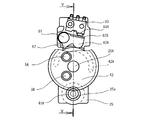
以下、本発明の実施の形態による打込機について、図1乃至図8に基づき説明する。図1に示される打込機である釘打機1は電動式であり、止具であるステープル1Aを被打込材である木材や石膏ボードなどの被打込材Wに打ち込んでいる。釘打機1は、ハウジング2と、モータ3と、減速機構4と、圧縮機構5と、コイルバネ部6と、マガジン7と、角度位置検出機構8とから主に構成されている。尚、後述のプランジャ63が移動する方向を上下方向と定義すると共にプランジャ63がコイルバネ部6を構成する後述のコイルバネ62により付勢されてステープル1Aを打撃する方向を下方向と定義し、後述のハンドル22が延出される方向を後方向、反対を前方向と定義して以下説明する。   Hereinafter, a driving machine according to an embodiment of the present invention will be described with reference to FIGS. 1 to 8. A nailing machine 1 which is a driving machine shown in FIG. 1 is an electric type, and staples 1A which are stoppers are driven into a material to be driven W such as wood or gypsum board which is a material to be driven. The nailing machine 1 mainly includes a housing 2, a motor 3, a speed reduction mechanism 4, a compression mechanism 5, a coil spring portion 6, a magazine 7, and an angular position detection mechanism 8. A direction in which a plunger 63 to be described later moves is defined as a vertical direction, and a direction in which the plunger 63 is urged by a coil spring 62 that constitutes the coil spring portion 6 to strike the staple 1A is defined as a downward direction. The direction in which the handle 22 extends is defined as a rear direction, and the opposite direction is defined as a front direction.

ハウジング2は、ナイロンまたはポリカーボネイト等の樹脂から構成されている。ハウジング2は、圧縮機構5、コイルバネ部6、ブレードガイド7が主に内蔵されるメインボディ21と、メインボディ21の上側部分から上下方向と略直交する方向へ延出されるハンドル22と、主にモータ3、減速機構4が主に内蔵され、メインボディ21の下側部分からハンドル22と略平行に延出されるサブボディ23とから主に構成されている。   The housing 2 is made of a resin such as nylon or polycarbonate. The housing 2 includes a main body 21 mainly including a compression mechanism 5, a coil spring portion 6, and a blade guide 7, a handle 22 extending from an upper portion of the main body 21 in a direction substantially perpendicular to the vertical direction, The motor 3 and the speed reduction mechanism 4 are mainly built in, and are mainly composed of a sub-body 23 that extends from the lower part of the main body 21 substantially parallel to the handle 22.

メインボディ21の最下端部分には、後述のドライバブレード6Aを保持するブレードガイド26が埋設され、下方に向けて突出するノーズ21Aが設けられている。ノーズ21Aにおいて、ブレードガイド26の後面側には、ブレードガイド26を画成する壁の一部とする射出孔21aが形成されている。この射出孔21aはメインボディ21において後述のプランジャ63位置まで貫通している。またブレードガイド26の上方には、後述のドライバブレード6A前面に位置する図示せぬカバープレートが配置されている。ノーズ21A近傍のメインボディ21内下側部分には、コイルバネ部6を受ける受部21Bが形成されている。受部21B内において略中央部分には上方に開口しコイルバネ部6が嵌合する下部穿孔21bが形成されている。   A blade guide 26 that holds a later-described driver blade 6A is embedded in the lowermost end portion of the main body 21, and a nose 21A that protrudes downward is provided. In the nose 21 </ b> A, an injection hole 21 a that is a part of a wall that defines the blade guide 26 is formed on the rear surface side of the blade guide 26. The injection hole 21a passes through the main body 21 to a position of a plunger 63 described later. Above the blade guide 26, a cover plate (not shown) located in front of the driver blade 6A described later is disposed. A receiving portion 21 </ b> B that receives the coil spring portion 6 is formed in the lower part of the main body 21 near the nose 21 </ b> A. A lower perforation 21b that opens upward and fits the coil spring portion 6 is formed in a substantially central portion in the receiving portion 21B.

またメインボディ21内においてコイルバネ部6の上方には、コイルバネ部6と嵌合する上部穿孔21cが形成されている。   Further, an upper perforation 21 c that fits with the coil spring portion 6 is formed in the main body 21 above the coil spring portion 6.

メインボディ21において側壁部分かつ受部21B近傍上方位置に、図3に示されるように後述のアジャスタ66の外周部分が露出する開口21dが形成されている。メインボディ21の内面であって開口21dの上方に位置する部分には、図4(A)に示されるように、上下方向に延びる一対のレール21C、21Cが両側壁に設けられている。また開口21dの近傍には、金属板から構成されてアジャスタ66の溝加工された外周と係合する凸状部21Dが設けられている。   As shown in FIG. 3, an opening 21 d is formed in the main body 21 at a side wall portion and in an upper position in the vicinity of the receiving portion 21 </ b> B, as shown in FIG. 3. As shown in FIG. 4A, a pair of rails 21C and 21C extending in the vertical direction is provided on both side walls on the inner surface of the main body 21 and above the opening 21d. Further, in the vicinity of the opening 21d, a convex portion 21D made of a metal plate and engaged with the outer periphery of the adjuster 66 which is grooved is provided.

メインボディ21においてコイルバネ部6の前側には、下端がノーズ21A先端より突出し、メインボディ21に対して上下動可能なプッシュレバー24が設けられている。プッシュレバー24は、ノーズ21Aを被加工材と当接させることによりノーズ21A先端から縮退し、メインボディ21内を上方に移動するように構成されている。プッシュレバー24の後端には、プッシュレバー24をメインボディ21に対して下側に付勢する付勢部材24Aが配置されている。よってプッシュレバー24は、上側に付勢されない限り常時ノーズ21Aから突出した状態を採っている。   In the main body 21, a push lever 24 that protrudes from the tip of the nose 21 </ b> A and can move up and down with respect to the main body 21 is provided on the front side of the coil spring portion 6. The push lever 24 is configured to retract from the tip of the nose 21 </ b> A by bringing the nose 21 </ b> A into contact with the workpiece and move upward in the main body 21. At the rear end of the push lever 24, an urging member 24A for urging the push lever 24 downward with respect to the main body 21 is disposed. Therefore, the push lever 24 is always in a state of protruding from the nose 21A unless urged upward.

またプッシュレバー24には、コイルバネ部6を跨いで後側に延出されるアーム部24Bを有している。メインボディ21において、アーム部24Bの上方にはプッシュスイッチ24Cが配置されており、プッシュレバー24が上方に移動したことを感知している。   Further, the push lever 24 has an arm portion 24 </ b> B that extends to the rear side across the coil spring portion 6. In the main body 21, a push switch 24C is disposed above the arm portion 24B, and senses that the push lever 24 has moved upward.

メインボディ21内において、コイルバネ部6の後方には、後述の遊星ギア機構41、ファイナルギア42を保持するギアホルダ25が配置されている。ギアホルダ25には、上下方向においてハンドル22とサブボディ23との間の位置に、ファイナルギア42を軸支する支持軸部25Aが前後方向を軸方向とし前方に向けて突出して設けられ、上下方向においてサブボディ23が配置される位置に、遊星ギア機構41が挿入される貫通孔25aが前後方向を貫通方向として形成されている。   In the main body 21, a gear holder 25 that holds a planetary gear mechanism 41 and a final gear 42 described later is disposed behind the coil spring portion 6. The gear holder 25 is provided with a support shaft portion 25A that pivotally supports the final gear 42 at a position between the handle 22 and the sub-body 23 in the vertical direction and projects forward with the front-rear direction as the axial direction. A through hole 25a into which the planetary gear mechanism 41 is inserted is formed at the position where the sub body 23 is disposed, with the front-rear direction as the through direction.

ハンドル22には、メインボディ21との接続部分にモータ3の制御を行うトリガ22A及びトリガスイッチ22Bが設けられている。ハンドル22の後端には、着脱式の電池2Aが設けられている。またハンドル22の内部において電池2A近傍位置には、プッシュスイッチ24C、トリガスイッチ22B、及び後述の検知スイッチ73、マイクロスイッチ83からの検出結果に基づいて、電池2Aから供給される電力をモータ3に制御・供給する電源制御部2Bが設けられている。   The handle 22 is provided with a trigger 22 </ b> A and a trigger switch 22 </ b> B for controlling the motor 3 at a connection portion with the main body 21. A detachable battery 2 </ b> A is provided at the rear end of the handle 22. Further, in the vicinity of the battery 2A inside the handle 22, the electric power supplied from the battery 2A is supplied to the motor 3 based on the detection results from the push switch 24C, the trigger switch 22B, the detection switch 73 and the micro switch 83 described later. A power supply control unit 2B for controlling and supplying is provided.

サブボディ23には、その下側にマガジン7が前後方向に延出される形で配置されている。   The magazine 7 is arranged on the lower side of the sub body 23 so as to extend in the front-rear direction.

モータ3は回転軸部31を有しており、回転軸部31の軸方向が前後方向と平行になるように配置されている。   The motor 3 has a rotating shaft portion 31 and is arranged so that the axial direction of the rotating shaft portion 31 is parallel to the front-rear direction.

減速機構4は、モータ3の前方にモータ3と同軸的に配置されており、遊星ギア機構41とファイナルギア42から主に構成されている。遊星ギア機構41は、回転軸部31の端部位置に設けられており、貫通孔25a内に装着されてギアホルダ25に保持され、回転軸部31に装着される太陽ギア、公転ギア、及び出力ギア41A等を含む公知のギア機構である。遊星ギア機構41の出力ギア41Aは回転軸部31と同軸上に配置されている。ファイナルギア42は、出力ギア41Aと噛合し、支持軸部25Aに回転可能に支持されると共に、ファイナルギア42の後端面とギアホルダ25の前面との間の距離が、後述のスイッチレバー82の板厚より僅かに大きくなるように構成されている。またファイナルギア42の後側端面には、後述のスイッチレバー82が当接する突起部42Aが設けられている。突起部42Aは、ファイナルギア42の円周方向に約180度に渡って配置される円弧形状を成しており、後端側面からの突出量が、後述のスイッチレバー82の板厚より僅かに大きくなるように構成されている。   The speed reduction mechanism 4 is disposed coaxially with the motor 3 in front of the motor 3, and mainly includes a planetary gear mechanism 41 and a final gear 42. The planetary gear mechanism 41 is provided at the end position of the rotary shaft portion 31, is mounted in the through hole 25 a and is held by the gear holder 25, and is attached to the rotary shaft portion 31, a sun gear, a revolving gear, and an output This is a known gear mechanism including the gear 41A and the like. The output gear 41 </ b> A of the planetary gear mechanism 41 is arranged coaxially with the rotary shaft portion 31. The final gear 42 meshes with the output gear 41A, is rotatably supported by the support shaft portion 25A, and the distance between the rear end surface of the final gear 42 and the front surface of the gear holder 25 is a plate of the switch lever 82 described later. It is configured to be slightly larger than the thickness. In addition, a projection 42A with which a switch lever 82 described later abuts is provided on the rear end face of the final gear 42. The projecting portion 42A has an arc shape that is arranged over about 180 degrees in the circumferential direction of the final gear 42, and the amount of protrusion from the rear end side surface is slightly smaller than the plate thickness of the switch lever 82 described later. It is configured to be large.

圧縮機構5は、回転体であるファイナルギア42の前側端面から前側に向けて突出される第一掛止部5Aと第二掛止部5Bとから構成されており、図2に示されるように、前側前面において、支持軸部25Aの軸心を中心とした同心円上に約120度の間隔をおいて時計回りの先端側に第一掛止部5A、後端側に第二掛止部5Bが配置されている。   The compression mechanism 5 includes a first hooking portion 5A and a second hooking portion 5B that protrude from the front end face of the final gear 42, which is a rotating body, toward the front side. As shown in FIG. On the front side of the front side, the first hooking portion 5A is located on the concentric circle centered on the axis of the support shaft portion 25A at an interval of about 120 degrees, and the second hooking portion 5B is located on the rear end side. Is arranged.

第一掛止部5A、第二掛止部5Bは、図5に示されるように、それぞれ略同径の第一ピン51及び第一ローラ53、第二ピン52及び第二ローラ54から構成されており、第一ピン51及び第一ローラ53に比べて第二ピン52及び第二ローラ54の方が前後方向における長さが大きくなるように構成されている。また第一ローラ53及び第二ローラ54がプランジャ63との係合箇所になる。   As shown in FIG. 5, the first latching portion 5 </ b> A and the second latching portion 5 </ b> B are each composed of a first pin 51 and a first roller 53, a second pin 52 and a second roller 54 having substantially the same diameter. The second pin 52 and the second roller 54 are configured such that the length in the front-rear direction is larger than that of the first pin 51 and the first roller 53. Further, the first roller 53 and the second roller 54 are engaged with the plunger 63.

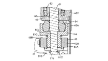
第一ピン51は、ファイナルギア42の前側端面から延出される略円柱状の第一基部51Aと、第一基部51Aの前側に配置されて第一基部51Aより大径であって略円柱状であり第一ローラ53を回転可能に支持する第一フランジ51Bとを備えて構成されている。第一基部51Aにおいて第一フランジ51Bと接続される箇所には、加工上の都合(直交形状を形成することが容易ではない)により、第一基部51Aの周方向に亘って前後方向の幅dの溝51a(図6(a))が形成されている。第一ローラ53は、前後方向に連通する第一孔53a、第二孔53bから環状に構成され、第一ピン51に回転可能に装着されている。第一孔53aは、第一フランジ51Bと略同形状に形成されており、第一孔53a内の内周が第一フランジ51Bの外周と摺動するように構成されている。第二孔53bは、第一フランジ51Bより小径で、第一基部51Aより大径に構成され、第一基部51Aが挿通している。第一フランジ51Bの外周が第二孔53bより大径なため、第一ローラ53が第一ピン51より脱落することが抑制されている。また第一ローラ53において、第一孔53aの穿設深さは、第一フランジ51Bの前後方向長さと略同じになるように構成されている。よって第一フランジ51Bと第一ローラ53とのそれぞれの前端は同一平面上に配置される。   The first pin 51 has a substantially cylindrical first base portion 51A extending from the front end face of the final gear 42, and is disposed on the front side of the first base portion 51A and has a larger diameter than the first base portion 51A and is substantially cylindrical. And a first flange 51 </ b> B that rotatably supports the first roller 53. A width d in the front-rear direction over the circumferential direction of the first base portion 51A is provided at a location connected to the first flange 51B in the first base portion 51A for convenience of processing (it is not easy to form an orthogonal shape). The groove 51a (FIG. 6A) is formed. The first roller 53 is formed in an annular shape from a first hole 53 a and a second hole 53 b that communicate with each other in the front-rear direction, and is rotatably attached to the first pin 51. The first hole 53a is formed in substantially the same shape as the first flange 51B, and is configured such that the inner periphery in the first hole 53a slides with the outer periphery of the first flange 51B. The second hole 53b has a smaller diameter than the first flange 51B and a larger diameter than the first base 51A, and the first base 51A is inserted therethrough. Since the outer periphery of the first flange 51B has a larger diameter than the second hole 53b, the first roller 53 is prevented from falling off from the first pin 51. In the first roller 53, the depth of the first hole 53a is configured to be substantially the same as the length in the front-rear direction of the first flange 51B. Therefore, the front ends of the first flange 51B and the first roller 53 are arranged on the same plane.

第二ピン52及び第二ローラ54も第一ピン51及び第一ローラ53と同様に第二基部52A第二フランジ52B、及び溝52a(図6(a))と、第一孔54A及び第二孔54bを備えて構成され、第二ローラ54が第二フランジ52Bに摺動・回転可能に支持されている。尚、第二掛止部5Bは第一掛止部5Aより突出しているため、第一フランジ51Bに比べて第二フランジ52Bの方が前後方向における距離が大きく構成されている。これに合わせて第一ローラ53の第一孔53aより第二ローラ54の第一孔54Aの方の穿設深さが大きく形成されている。故に、第一ローラ53と第一フランジ51Bとが接触する面積より、第二ローラ54と第二フランジ53Bとが接触する面積の方が大きくなる。   Similarly to the first pin 51 and the first roller 53, the second pin 52 and the second roller 54 also have a second base 52A, a second flange 52B, a groove 52a (FIG. 6A), a first hole 54A, and a second roller. The second roller 54 is supported by the second flange 52B so as to be slidable and rotatable. Since the second hooking portion 5B protrudes from the first hooking portion 5A, the second flange 52B has a greater distance in the front-rear direction than the first flange 51B. Accordingly, the drilling depth of the first hole 54A of the second roller 54 is larger than that of the first hole 53a of the first roller 53. Therefore, the area where the second roller 54 and the second flange 53B contact each other is larger than the area where the first roller 53 and the first flange 51B contact each other.

図1に示されるように、コイルバネ部6は、シャフト61と、コイルバネ62とプランジャ63と、バンパ64と、バンパホルダ65と、アジャスタ66とを主に備え、これら構成部材からユニット状に構成されている。シャフト61は円柱状に構成され、最上端に鍔部61Aが設けられ、最下端に位置規定部61Bが規定されている。この位置規定部61Bが下部穿孔21bに挿入されて固定され、鍔部61Aが上部穿孔21cに挿入されて固定されることにより、コイルバネ部6のハウジング2内における位置が正確に規定され、かつ使用時にシャフト61がハウジング2に対してずれることが抑制される。またシャフト61の下端において位置規定部61B近傍には、シャフト61の周回りに溝が形成され、この溝にCリング状のトメワ61Cが装着されている。シャフト61においては、このトメワ61Cより上方にコイルバネ62、プランジャ63、バンパ64、アジャスタ66が装着されている。   As shown in FIG. 1, the coil spring portion 6 mainly includes a shaft 61, a coil spring 62, a plunger 63, a bumper 64, a bumper holder 65, and an adjuster 66, and is configured as a unit from these constituent members. Yes. The shaft 61 is formed in a columnar shape, and a flange portion 61A is provided at the uppermost end, and a position defining portion 61B is defined at the lowermost end. The position defining portion 61B is inserted and fixed in the lower perforation 21b, and the collar portion 61A is inserted and fixed in the upper perforation 21c, whereby the position of the coil spring portion 6 in the housing 2 is accurately defined and used. Occasionally, the shaft 61 is prevented from being displaced with respect to the housing 2. Further, a groove is formed around the circumference of the shaft 61 in the vicinity of the position defining portion 61B at the lower end of the shaft 61, and a C-ring shaped tow 61C is mounted in this groove. In the shaft 61, a coil spring 62, a plunger 63, a bumper 64, and an adjuster 66 are mounted above the tome 61 </ b> C.

コイルバネ62は、鋼線が螺旋状に巻回されて構成され、内部にシャフト61が貫通するようにシャフト61に配置されている。またコイルバネ62の上側には、一対のワッシャ62B、62Bがシャフト61に装着されて配置され、一対のワッシャ62B、62Bの間には、リング状を成す樹脂等の弾性体62Aが挟まれている。ワッシャ62Bは内径が鍔部61Aの外径より小径に構成されている。よってコイルバネ62の上端は、一対のワッシャ62B、62Bと弾性体62Aとよって上方への移動が規制されている。   The coil spring 62 is configured by winding a steel wire in a spiral shape, and is disposed on the shaft 61 so that the shaft 61 passes through the coil spring 62. A pair of washers 62B and 62B is mounted on the shaft 61 on the upper side of the coil spring 62, and a ring-shaped elastic body 62A such as a resin is sandwiched between the pair of washers 62B and 62B. . The washer 62B has an inner diameter smaller than the outer diameter of the flange 61A. Therefore, the upper end of the coil spring 62 is restricted from moving upward by the pair of washers 62B and 62B and the elastic body 62A.

コイルバネ62の下側にも同様の構成の一対のワッシャ62B、62Bと弾性体62Aとが配置されている。これら上下に配置された一対のワッシャ62B、62Bと弾性体62Aとにより、コイルバネ62に発生したサージングを吸収している。   A pair of washers 62B and 62B having the same configuration and an elastic body 62A are also arranged below the coil spring 62. The surging generated in the coil spring 62 is absorbed by the pair of washers 62B and 62B and the elastic body 62A arranged above and below.

プランジャ63は、貫通孔63aが上下方向に形成され、貫通孔63aをシャフト61が貫通してシャフト61に対して上下動可能に装着されると共にコイルバネ62の下側に配置されている。コイルバネ62の下端には一対のワッシャ62B、62Bと弾性体62Aとが配置されているため、これらワッシャ62B等を介してコイルバネ62と接している。またプランジャ63には、図6(a)、(b)に示されるように、後面側に被掛止部である第一引上突起部63Aと第二引上突起部63Bとが上下方向に整列して設けられ、前面側に突起部63Cが設けられている。   The plunger 63 has a through hole 63 a formed in the vertical direction, the shaft 61 passes through the through hole 63 a and is mounted to be movable up and down with respect to the shaft 61, and is disposed below the coil spring 62. Since a pair of washers 62B, 62B and an elastic body 62A are disposed at the lower end of the coil spring 62, the coil spring 62 is in contact with the coil spring 62 via these washers 62B. In addition, as shown in FIGS. 6A and 6B, the plunger 63 includes a first pulling protrusion 63A and a second pulling protrusion 63B that are hooked portions on the rear surface side in the vertical direction. The protrusions 63 </ b> C are provided on the front side.

第一引上突起部63Aは、プランジャ63の上端位置から後方へ向けて、第一掛止部5Aと係合可能な突出量を採るように突出している。第二引上突起部63Bは、プランジャ63の下端位置から後方へ向けて、第一掛止部5Aと係合不能かつ第二掛止部5Bと係合可能な突出量を採るように突出している。   63 A of 1st raising protrusion parts protrude toward the back from the upper end position of the plunger 63 so that the protrusion amount which can be engaged with 5 A of 1st latching parts is taken. The second pull-up protrusion 63B protrudes rearward from the lower end position of the plunger 63 so as to take an amount of protrusion that cannot be engaged with the first hook 5A and can be engaged with the second hook 5B. Yes.

また突起部63Cにはドライバブレード6Aが装着されている。ドライバブレード6Aは、細長い板状に構成されて上端部分に孔6aが形成され、孔6a内に突起部63Cが挿入されてプランジャ63に連結され、図1に示されるように射出孔21a内に上下動可能に配置されている。また射出孔21a内においてドライバブレード6A前側には、図示せぬカバープレートがあるため、ドライバブレード6Aが前方へ移動することが抑制され、故に、ドライバブレード6Aが突起部63Cから脱落することが抑制される。   A driver blade 6A is attached to the protrusion 63C. The driver blade 6A is formed in a long and narrow plate shape, and a hole 6a is formed at the upper end portion. A projection 63C is inserted into the hole 6a and connected to the plunger 63. As shown in FIG. 1, the driver blade 6A is inserted into the injection hole 21a. It is arranged to move up and down. In addition, since there is a cover plate (not shown) on the front side of the driver blade 6A in the injection hole 21a, the driver blade 6A is prevented from moving forward, and therefore the driver blade 6A is prevented from dropping from the protrusion 63C. Is done.

バンパ64は軟質ゴム、又はウレタン等の樹脂製であり、プランジャ63の下方に配置されて、プランジャ63の下端面と当接可能に構成されている。   The bumper 64 is made of a soft rubber or a resin such as urethane, and is disposed below the plunger 63 so as to be in contact with the lower end surface of the plunger 63.

図7に示されるように、バンパホルダ65はバンパ64を受ける受面を備えるバンパ受部65Aと、受面に対して反バンパ64側に位置するバンパ受部65A下面から下方に延出され上下方向を螺進退方向とする雄ネジ部65Bと、バンパ受部65A部の下面に規定され、上下方向と直交する平面であるホルダ側座面65Cとを備えて構成されている。またバンパホルダ65にはバンパ受部65Aと雄ネジ部65Bとを貫通する貫通孔65aが上下方向に形成されている。よってバンパホルダ65は、貫通孔65aをシャフト61が貫通してシャフト61に対して上下動可能に装着される。   As shown in FIG. 7, the bumper holder 65 extends downward from a bumper receiving portion 65A having a receiving surface for receiving the bumper 64, and a lower surface of the bumper receiving portion 65A located on the side opposite to the bumper 64 with respect to the receiving surface. Is provided with a male thread portion 65B having a screw advance / retreat direction and a holder side seating surface 65C that is defined on the lower surface of the bumper receiving portion 65A and is a plane orthogonal to the vertical direction. The bumper holder 65 is formed with a through-hole 65a extending vertically through the bumper receiving portion 65A and the male screw portion 65B. Therefore, the bumper holder 65 is mounted so that the shaft 61 passes through the through-hole 65 a and can move up and down with respect to the shaft 61.

図4(a)に示されるように、バンパ受部65Aには、外周部分が二面加工されて面65D、65Dが形成されており、この面65D、65Dがメインボディ21の両側壁内に形成されたレール21C、21Cに挟まれる様に、バンパホルダ65がメインボディ21内に配置される。一の面65Dから他の面65Dまでの距離は、メインボディ21の一の側壁内のレール21Cから他の側壁内のレール21Cまでの距離より僅かに短くなるように構成されている。よってバンパホルダ65はメインボディ21内で僅かなガタを有しスムーズに上下動することができる。尚、メインボディ21とバンパホルダ65との間にはガタがあるので、メインボディ21に対してバンパホルダ65が例えば180°回転することはないが、図4(b)、(c)に示されるように、10°程度の僅かな角度で回転することは許容されている。   As shown in FIG. 4A, the outer peripheral portion of the bumper receiving portion 65A is processed into two surfaces 65D and 65D, and these surfaces 65D and 65D are formed in both side walls of the main body 21. A bumper holder 65 is arranged in the main body 21 so as to be sandwiched between the formed rails 21C and 21C. The distance from one surface 65D to the other surface 65D is configured to be slightly shorter than the distance from the rail 21C in one side wall of the main body 21 to the rail 21C in the other side wall. Therefore, the bumper holder 65 has a slight backlash in the main body 21 and can move up and down smoothly. Since there is a backlash between the main body 21 and the bumper holder 65, the bumper holder 65 does not rotate, for example, 180 ° with respect to the main body 21, but as shown in FIGS. 4B and 4C. Further, it is allowed to rotate at a slight angle of about 10 °.

図7に示されるように雄ネジ部65BはM12のネジと同様の規格で形成されている。また貫通孔65aの孔径は、シャフト61に装着されたトメワ61Cの外径より小さくなるように形成されている。   As shown in FIG. 7, the male screw portion 65B is formed according to the same standard as the M12 screw. Further, the through hole 65a is formed so that the hole diameter is smaller than the outer diameter of the tome 61C attached to the shaft 61.

アジャスタ66は環状に構成されており、内周部分に雄ネジ部65Bと螺合する雌ネジ部66Aが設けられ、上面にホルダ側座面65Cと対峙するネジ部側座面66Bが規定され、外周部分に溝加工が施され、この外周部分が開口21d(図3)から露出するように下面がメインボディ21の受部21Bと当接している。またアジャスタ66は雌ネジ部66Aによりバンパホルダ65の雄ネジ部65Bと螺合しているため、アジャスタ66をバンパホルダ65に対して時計回り・反時計回りに回転させることにより、バンパホルダ65がアジャスタ66に対して上下方向に移動することができる。尚、図3に示されるように、アジャスタ66は、ハウジング2内に装着された状態で、外周が凸状部21Dと係合する。よって意図しないアジャスタ66の回転は抑制されている。   The adjuster 66 is formed in an annular shape, and is provided with a female screw portion 66A that is screwed to the male screw portion 65B on the inner peripheral portion, and a screw portion side seating surface 66B that faces the holder side seating surface 65C is defined on the upper surface. Groove processing is performed on the outer peripheral portion, and the lower surface is in contact with the receiving portion 21B of the main body 21 so that the outer peripheral portion is exposed from the opening 21d (FIG. 3). Further, since the adjuster 66 is screwed with the male screw portion 65B of the bumper holder 65 by the female screw portion 66A, the bumper holder 65 is moved to the adjuster 66 by rotating the adjuster 66 clockwise or counterclockwise with respect to the bumper holder 65. On the other hand, it can move up and down. As shown in FIG. 3, the adjuster 66 is fitted in the housing 2, and the outer periphery engages with the convex portion 21 </ b> D. Therefore, unintended rotation of the adjuster 66 is suppressed.

上述のように、アジャスタ66がハウジング2の受部21Bと当接しているため、アジャスタ66と螺合しているバンパホルダ65は、アジャスタ66に対して上方に移動することにより、ハウジング2に対して上方向に移動することになる。また上述のように、シャフト61はハウジング2に両端が固定されているため、ハウジング2に対して上方向に移動するバンパホルダ65は、シャフト61に対して上方向に移動する。バンパホルダ65の上にはバンパ64があり、バンパ64はプランジャ63が当接する箇所であってプランジャ63の下死点を規定している。またプランジャ63にはドライバブレード6Aが装着されているため、アジャスタ66の回転操作により、ドライバブレード6Aの下死点位置、即ちドライバブレード6Aの被打込材Wへの打込深さを変更することができる。   As described above, since the adjuster 66 is in contact with the receiving portion 21 </ b> B of the housing 2, the bumper holder 65 screwed with the adjuster 66 moves upward with respect to the adjuster 66, thereby It will move upward. As described above, since both ends of the shaft 61 are fixed to the housing 2, the bumper holder 65 that moves upward relative to the housing 2 moves upward relative to the shaft 61. A bumper 64 is provided on the bumper holder 65, and the bumper 64 is a place where the plunger 63 abuts and defines the bottom dead center of the plunger 63. Further, since the driver blade 6A is mounted on the plunger 63, the bottom dead center position of the driver blade 6A, that is, the driving depth of the driver blade 6A into the workpiece W is changed by the rotation operation of the adjuster 66. be able to.

また図7に示されるように、ホルダ側座面65Cとネジ部側座面66Bとの間には、シャフト61が貫通するOリング67が配置されている。Oリング67はゴム等の弾性体から構成されており、その表面には、摩耗防止のためのグリスが塗布されている。   Further, as shown in FIG. 7, an O-ring 67 through which the shaft 61 passes is disposed between the holder side seating surface 65C and the screw portion side seating surface 66B. The O-ring 67 is made of an elastic body such as rubber, and its surface is coated with grease for preventing wear.

尚、上述のように、コイルバネ62、プランジャ63、バンパ64、バンパホルダ65、アジャスタ66、及びOリング67がシャフト61に装着された状態でトメワ61Cを嵌めることにより、コイルバネ62〜Oリング67がシャフト61から脱落することが防がれる。よってシャフト61〜Oリング67はユニット化され、上述のようにシャフト61を下側穿孔21b、上側穿孔21cに挿入してハウジング2に固定・装着することにより、コイルバネ62〜Oリング67も同様にハウジング2に装着される。   As described above, when the coil spring 62, the plunger 63, the bumper 64, the bumper holder 65, the adjuster 66, and the O-ring 67 are attached to the shaft 61 and the tomewa 61C is fitted, the coil spring 62 to the O-ring 67 are connected to the shaft. It is prevented from dropping from 61. Therefore, the shaft 61 to the O-ring 67 are unitized. As described above, the shaft 61 is inserted into the lower perforation 21b and the upper perforation 21c, and fixed to the housing 2 so that the coil spring 62 to the O-ring 67 are similarly installed. Mounted on the housing 2.

図1に示される様に、マガジン7は、ホルダ71とプッシャ72と検知スイッチ73とから主に構成されており、後述のプッシャ72がステープル1Aを付勢する方向が前後方向と平行になるように、サブボディ23の下側に配置されている。ホルダ71は、整列された複数のステープル1Aを保持しており、ホルダ71の前側端部が射出孔21a内においてブレードガイド26後側に位置に位置している。よってステープル1Aは、射出孔21a内においてブレードガイド26後側位置に供給される。   As shown in FIG. 1, the magazine 7 is mainly composed of a holder 71, a pusher 72, and a detection switch 73, and the direction in which the pusher 72 described later urges the staple 1A is parallel to the front-rear direction. Further, it is disposed below the sub body 23. The holder 71 holds a plurality of aligned staples 1A, and the front end of the holder 71 is positioned at the rear side of the blade guide 26 in the ejection hole 21a. Therefore, the staple 1A is supplied to the rear position of the blade guide 26 in the ejection hole 21a.

プッシャ72は、ホルダ71に装着され、図示せぬバネにより前側に付勢されており、複数のステープル1Aの後方に配置されている。よって複数のステープル1Aは、順次射出孔21a内に供給される。またプッシャ72の後端部分には、検知スイッチ73と接触可能な、片部72Aが設けられている。   The pusher 72 is attached to the holder 71 and biased forward by a spring (not shown), and is disposed behind the plurality of staples 1A. Therefore, the plurality of staples 1A are sequentially supplied into the ejection holes 21a. Further, at the rear end portion of the pusher 72, a piece portion 72A that can come into contact with the detection switch 73 is provided.

検知スイッチ73は、ホルダ71の上方に位置するサブボディ23に配置され、プッシャ72が所定の位置(例えば残りのステープル1Aの数が一本となる位置)に移動した時に、片部72Aと当接するように構成されている。   The detection switch 73 is disposed on the sub body 23 located above the holder 71, and abuts against the one portion 72A when the pusher 72 moves to a predetermined position (for example, a position where the number of remaining staples 1A becomes one). It is configured as follows.

図2に示されるように、角度位置検出機構8は、レバーピン81とスイッチレバー82と、マイクロスイッチ83とから構成されている。レバーピン81は、ギアホルダ25の前面であってファイナルギア42上方に、前後方向を軸方向として装着されている。スイッチレバー82は、レバーピン81に回動可能に軸支され、突起部42Aと当接する当接位置と突起部42Aと非当接の初期位置との間で移動可能であり、図5に示されるように、突起部42Aの突出量より薄い板厚の金属板が折り曲げられて略L字状を成すように構成されている。スイッチレバー82の断面略L字状を成す一片であって前後方向と直交する板部分に突起部当接部82Aが規定され、略L字状を成す他片であって前後方向と平行な板部分に検出部当接部82Bが規定されている。   As shown in FIG. 2, the angular position detection mechanism 8 includes a lever pin 81, a switch lever 82, and a micro switch 83. The lever pin 81 is mounted on the front surface of the gear holder 25 and above the final gear 42 with the front-rear direction as the axial direction. The switch lever 82 is pivotally supported by the lever pin 81 and is movable between a contact position where the switch lever 82 comes into contact with the protrusion 42A and a non-contact initial position with the protrusion 42A, as shown in FIG. As described above, the metal plate having a thickness smaller than the protruding amount of the protruding portion 42A is bent to form a substantially L shape. The switch lever 82 is a piece having a substantially L-shaped cross-section, and a protrusion abutting portion 82A is defined on a plate portion orthogonal to the front-rear direction, and a plate that is substantially L-shaped and parallel to the front-rear direction. The detection part contact part 82B is prescribed | regulated to the part.

突起部当接部82Aは、ギアホルダ25とファイナルギア42との間の隙間に突起部42Aと当接可能に配置されている。ギアホルダ25とファイナルギア42との間の隙間は、突起部当接部82Aの板厚より僅かに大きい程度であるため、突起部当接部82Aが突起部42Aからずれて外れることは抑制される。また突起部当接部82Aは、図2に示されるように外形が曲線形状に構成されており、曲線形状が突起部42Aと当接するように構成されている。   The projecting portion abutting portion 82A is disposed in the gap between the gear holder 25 and the final gear 42 so as to be able to abut on the projecting portion 42A. Since the gap between the gear holder 25 and the final gear 42 is slightly larger than the thickness of the protruding portion abutting portion 82A, the protruding portion abutting portion 82A is prevented from being displaced from the protruding portion 42A. . Further, as shown in FIG. 2, the protruding portion abutting portion 82A has a curved outer shape, and the curved shape is configured to contact the protruding portion 42A.

検出部当接部82Bは、図5に示されるようにファイナルギア42の半径方向においてファイナルギア42外周と対向するように配置されている。   As shown in FIG. 5, the detector contact portion 82 </ b> B is disposed so as to face the outer periphery of the final gear 42 in the radial direction of the final gear 42.

マイクロスイッチ83は、検出部当接部82Bの上方に位置し、スイッチレバー82が当接位置に移動した時に、付勢されるスイッチ83Aを備えている。スイッチ83Aは図示せぬバネで付勢されているため、スイッチレバー82と突起部42Aとの当接状態が解かれた時に、スイッチレバー82を突起部42Aと当接可能な位置(初期位置)に押し戻すことができる。この様な構成によると、スイッチレバー82が突起部42に付勢される力が最小限ですむため、スイッチレバー82と突起部42との磨耗が抑えられ、高寿命化を図ることができる。また部品点数を増やさずに、スイッチレバー82を確実に初期位置に戻すことができる。尚、スイッチ82Aの反力の他にも、例えばスイッチレバー82とギアホルダ25との間にスイッチレバー82を初期位置側に付勢するバネ等を介在させてもよい。   The micro switch 83 is provided above the detection unit abutting portion 82B and includes a switch 83A that is biased when the switch lever 82 moves to the abutting position. Since the switch 83A is biased by a spring (not shown), when the contact state between the switch lever 82 and the projection 42A is released, the switch lever 82 can be brought into contact with the projection 42A (initial position). Can be pushed back to. According to such a configuration, since the force with which the switch lever 82 is urged by the protrusion 42 is minimized, wear of the switch lever 82 and the protrusion 42 can be suppressed, and the life can be extended. Further, the switch lever 82 can be reliably returned to the initial position without increasing the number of parts. In addition to the reaction force of the switch 82A, for example, a spring or the like that biases the switch lever 82 toward the initial position may be interposed between the switch lever 82 and the gear holder 25.

上記構成の釘打機1で作業を行う際には、まずステープル1Aを打ち込む被打込部材Wに合わせて、アジャスタ66を回転させ、ステープル1Aの打込深さを調整する。その後に、ノーズ21A先端を被打込部材Wに接触させて、プッシュレバー24をハウジング2に対して後退させ、プッシュスイッチ24Cをオンにする。この動作と前後して、トリガ22Aを引き、トリガスイッチ22Bをオンにする。電源制御部2Bにおいては、プッシュスイッチ24Cからのオン信号及びトリガスイッチ22Bからのオン信号を検出することにより、モータ3に電力を供給して駆動させる。   When working with the nailing machine 1 having the above-described configuration, first, the adjuster 66 is rotated in accordance with the driven member W into which the staple 1A is driven, and the driving depth of the staple 1A is adjusted. Thereafter, the tip of the nose 21A is brought into contact with the driven member W, the push lever 24 is moved backward with respect to the housing 2, and the push switch 24C is turned on. Before and after this operation, the trigger 22A is pulled and the trigger switch 22B is turned on. The power supply control unit 2B supplies power to the motor 3 to drive it by detecting an on signal from the push switch 24C and an on signal from the trigger switch 22B.

モータ3が回転することにより、ファイナルギア42が回転し、先ず、第一掛止部5Aと第一引上突起部63Aとが係合してプランジャ63が上方へと移動される。ファイナルギア42が更に回転し、プランジャ63が上方へと移動した状態で、次に第二掛止部5Aと第二引上突起部63Bとが係合し、第二掛止部5Bがプランジャ63を更に上方へと移動させる。第二係止部5Bと第二引上突起部63Bとの係合が発生してプランジャ63が上方に移動することにより、第一係止部5Aと第一引上突起部63Aとの係合は解かれる。   As the motor 3 rotates, the final gear 42 rotates. First, the first latching portion 5A and the first pulling protrusion 63A are engaged, and the plunger 63 is moved upward. In a state where the final gear 42 further rotates and the plunger 63 has moved upward, the second hooking portion 5A and the second pulling protrusion 63B are next engaged, and the second hooking portion 5B is moved to the plunger 63. Is moved further upward. Engagement between the first locking part 5A and the first lifting protrusion 63A occurs when the engagement between the second locking part 5B and the second lifting protrusion 63B occurs and the plunger 63 moves upward. Is solved.

この状態からファイナルギア42が更に回転すると、第二掛止部5Bの円運動に起因して、第二係止部5Bが第二引上突起部63Bから離間する。プランジャ63が上方に移動することにより、コイルバネ62に弾性エネルギーが蓄積されコイルバネ62によりプランジャ63が付勢される。この状態で、第二係止部5Bが第二引上突起部63Bから離間することにより、プランジャ63が急激に下方へと移動し、これに伴い、ドライバブレード6Aによりステープル1Aが打撃され、被打込材Wにステープル1Aが打ち込まれる。   When the final gear 42 further rotates from this state, the second locking portion 5B is separated from the second pulling protrusion 63B due to the circular motion of the second hooking portion 5B. When the plunger 63 moves upward, elastic energy is accumulated in the coil spring 62 and the plunger 63 is urged by the coil spring 62. In this state, when the second locking portion 5B is separated from the second pulling protrusion 63B, the plunger 63 suddenly moves downward, and accordingly, the staple 1A is hit by the driver blade 6A, and the covered portion is covered. The staple 1A is driven into the driving material W.

ファイナルギア42の回転状態は、スイッチレバー82とマイクロスイッチ83との当接に基づくマイクロスイッチ83のからの検出信号により、電源制御部2Bで判断している。具体的には、第二係止部5Bが第二引上突起部63Bから離間すると同時に、スイッチレバー82と突起部42Aとの当接状態が解消されるように、突起部42Aを配置する。これにより、同時にスイッチレバー82は当接位置から初期位置に移動し、マイクロスイッチ83からオフ信号が出力される。スイッチレバー82と突起部42Aとが当接している状態では、マイクロスイッチ83からオン信号が出力されるため、このオン信号からオフ信号への切替に応じて、電源制御部2Bによりモータ3に供給する電力を停止することにより、ファイナルギア42が過度に回転することが抑制される。   The rotation state of the final gear 42 is determined by the power control unit 2B based on a detection signal from the micro switch 83 based on the contact between the switch lever 82 and the micro switch 83. Specifically, the protrusion 42A is arranged so that the contact state between the switch lever 82 and the protrusion 42A is eliminated at the same time as the second locking portion 5B is separated from the second pulling protrusion 63B. Accordingly, the switch lever 82 simultaneously moves from the contact position to the initial position, and an off signal is output from the micro switch 83. In a state where the switch lever 82 and the protrusion 42A are in contact with each other, an on signal is output from the micro switch 83, so that the power control unit 2B supplies the motor 3 with the switching from the on signal to the off signal. By stopping the power to be used, the final gear 42 is prevented from excessively rotating.

またステープル1Aが打撃され続け、残りが少なくなった場合は、プッシャ72の片部72Aが検知スイッチ73と当接し、検知スイッチ73からオン信号が出力される。電源制御部2Bが検知スイッチ73からの信号を検出した場合には、トリガスイッチ22B及びプッシュスイッチ24CからのON信号を検出したとしても、モータ3への電力供給は行わない。これにより、ステープル1Aが無い状態での空打ちを抑制している。   Further, when the staple 1A continues to be struck and the remaining amount is reduced, the piece 72A of the pusher 72 comes into contact with the detection switch 73, and an ON signal is output from the detection switch 73. When the power control unit 2B detects a signal from the detection switch 73, even if the ON signal from the trigger switch 22B and the push switch 24C is detected, power supply to the motor 3 is not performed. As a result, idling in the absence of the staple 1A is suppressed.

またステープル1Aの打込深さを最も深くした状態、即ちアジャスタ66を回転させてバンパホルダ65のバンパ受部65Aを最もアジャスタ66に近接させた状態については、ホルダ側座面65Dとネジ部側座面66Bとの間にOリング67が介在するため、図8に示されるようにホルダ側座面65Dとネジ部側座面66Bとが直接接触することはない。   Further, in the state where the driving depth of the staple 1A is the deepest, that is, in the state where the bumper receiving portion 65A of the bumper holder 65 is moved closest to the adjuster 66 by rotating the adjuster 66, the holder side seating surface 65D and the screw side seat. Since the O-ring 67 is interposed between the surface 66B, the holder side seating surface 65D and the screw portion side seating surface 66B do not directly contact each other as shown in FIG.

第一係止部5A、第二係止部5Bがそれぞれ第一引上突起部63A、第二引上突起部63Bを上方へと移動させる際には、第一係止部5A、第二係止部5Bが円運動するファイナルギア42に設けられていることから、第一係止部5A、第二係止部5Bから第一引上突起部63A、第二引上突起部63Bに、上下方向及び前後方向と直交する方向へと移動する力が作用する。第一係止部5A、第二係止部5Bでは、第一ローラ53、第二ローラ54がそれぞれ第一引上突起部63A、第二引上突起部63Bと当接しているため、第一係止部5A、第二係止部5Bがそれぞれ第一引上突起部63A、第二引上突起部63Bを上方へと移動させる際には、第一ローラ53、第二ローラ54が第一ピン51、第二ピン52に対して回転することにより、第一引上突起部63A、第二引上突起部63Bに対する第一係止部5A、第二係止部5Bの上下方向及び前後方向と直交する方向への移動が許容される。   When the first locking portion 5A and the second locking portion 5B move the first pulling protrusion 63A and the second pulling protrusion 63B upward, respectively, the first locking portion 5A and the second locking portion Since the stop portion 5B is provided on the final gear 42 that moves in a circular motion, the first pulling projection portion 63A and the second pulling projection portion 63B are moved up and down from the first locking portion 5A and the second locking portion 5B. The force which moves to the direction orthogonal to a direction and the front-back direction acts. In the first locking portion 5A and the second locking portion 5B, the first roller 53 and the second roller 54 are in contact with the first lifting protrusion 63A and the second lifting protrusion 63B, respectively. When the locking portion 5A and the second locking portion 5B move the first pulling projection 63A and the second pulling projection 63B upward, the first roller 53 and the second roller 54 are the first By rotating with respect to the pin 51 and the second pin 52, the first and second protrusions 63A and 63B, and the first and second engaging portions 5A and 5B with respect to the first and second protrusions 63A and 63B. Is allowed to move in a direction perpendicular to.

上記のようにコイルバネ62を圧縮した場合、コイルバネ62に蓄積される弾性エネルギーは、第一係止部5Aと第二引上突起部63Aとが係合した時に比べて、第二係止部5Bと第二引上突起部63Bとが係合した時の方が大きくなる。よってプランジャ63から受ける付勢力は、第一係止部5Aより第二係止部5Bの方が大きくなる。   When the coil spring 62 is compressed as described above, the elastic energy accumulated in the coil spring 62 is larger than that when the first locking portion 5A and the second pulling protrusion 63A are engaged with each other. And the second pulling protrusion 63B are larger when engaged. Therefore, the biasing force received from the plunger 63 is greater in the second locking portion 5B than in the first locking portion 5A.

第一ローラ53、第二ローラ54が上述のように第一ピン51、第二ピン52に対して回転する際には、第一孔53b、54bそれぞれの内周と、第一フランジ51B、第二フランジ52B外周とが摺動する。上述のように、第一係止部5Aより第二係止部5Bの方が受ける付勢力が大きいため、第一孔53b内面と第一フランジ51B外周との間に生じる負荷より、第一孔54b内面と第二フランジ52B外周との間に生じる負荷の方が大きくなる。しかし、上述のように、第一孔53b及び第一フランジ51Bより、第一孔54b及び第二フランジ52Bの方が前後方向の距離が大きいため、前後方向における単位長さに生じる負荷は、第一孔53b内面及び第一フランジ51B外周と第一孔54b内面及び第二フランジ52B外周とにおいて略同じにすることができる。   When the first roller 53 and the second roller 54 rotate with respect to the first pin 51 and the second pin 52 as described above, the inner circumferences of the first holes 53b and 54b, the first flange 51B, The outer periphery of the two flanges 52B slides. As described above, since the urging force received by the second locking portion 5B is larger than that of the first locking portion 5A, the first hole is larger than the load generated between the inner surface of the first hole 53b and the outer periphery of the first flange 51B. The load generated between the inner surface of 54b and the outer periphery of the second flange 52B becomes larger. However, as described above, the first hole 54b and the second flange 52B have a greater distance in the front-rear direction than the first hole 53b and the first flange 51B. The inner surface of the first hole 53b and the outer periphery of the first flange 51B and the inner surface of the first hole 54b and the outer periphery of the second flange 52B can be made substantially the same.

また本実施の形態に対する比較例として、従来の構成に係る第一、第二係止部と第一、第2引上突起部掛とを図9(a)(b)に示す。図9(a)の第一係止部105A及び第二係止部105Bでは、第一ピン151及び第二ピン152において、第一基部151A及び152Aにそれぞれ第一ローラ153及び第二ローラ154が摺動回転可能に装着され、第一基部151A及び152Aの先端に設けられた第一フランジ151B及び第二フランジ152Bにより、第一ローラ153及び第二ローラ154の抜けが防止されている。よって第一ローラ153及び第二ローラ154の前端に対して第一ピン151及び第二ピン152の前端の方が前側に位置することになる。また第一基部151Aの第一フランジ151Bとの境界部分には、本実施の形態と同様の加工上の都合による幅dの溝151aが形成され、第二基部152Aにも同様の溝152aが形成されている。また第一フランジ151Bの前後方向の距離をtと定義し、第二フランジ152Bの前後方向の距離をtと定義する。 Moreover, as a comparative example with respect to the present embodiment, the first and second locking portions and the first and second pull-up projection hooks according to the conventional configuration are shown in FIGS. In the first locking portion 105A and the second locking portion 105B in FIG. 9A, in the first pin 151 and the second pin 152, the first roller 153 and the second roller 154 are provided on the first base portions 151A and 152A, respectively. The first roller 153 and the second roller 154 are prevented from coming off by the first flange 151B and the second flange 152B that are mounted so as to be slidably rotatable and provided at the tips of the first bases 151A and 152A. Therefore, the front ends of the first pin 151 and the second pin 152 are located on the front side with respect to the front ends of the first roller 153 and the second roller 154. In addition, a groove 151a having a width d is formed at the boundary between the first base portion 151A and the first flange 151B for the same processing convenience as in the present embodiment, and a similar groove 152a is also formed in the second base portion 152A. Has been. The distance the front-rear direction of the first flange 151B is defined as t 1, the longitudinal length of the second flange 152B is defined as t 2.

この比較例においては、第一係止部105A及び第二係止部105Bと、第一引上突起部163A及び第二引上突起部163Bとに係る構成以外は、本実施の形態と略同じ構成を採っている。また比較例において第一ローラ153及び第二ローラ154は、本実施の形態に係る第一ローラ53及び第二ローラ54と外形及び前後方向長さが等しくなるように構成されている。   This comparative example is substantially the same as the present embodiment except for the configuration relating to the first locking portion 105A and the second locking portion 105B, and the first pulling protrusion portion 163A and the second pulling protrusion portion 163B. The composition is taken. In the comparative example, the first roller 153 and the second roller 154 are configured to have the same outer shape and longitudinal length as the first roller 53 and the second roller 54 according to the present embodiment.

この比較例と本実施の形態とにおいて、シャフトからファイナルギアまでの距離について比較する。尚、比較例と本実施の形態とにおいて、それぞれ前後方向における第一、第二ローラと第一、第二引上突起部との係合している箇所の距離は等しくなるように構成されている。   In this comparative example and this embodiment, the distance from the shaft to the final gear is compared. In the comparative example and the present embodiment, the distances between the engaging positions of the first and second rollers and the first and second lifting protrusions in the front-rear direction are equal. Yes.

図6(b)に示されるように、本実施の形態において、シャフト61からファイナルギア42の前側端面までの距離をLと定義し、シャフト61から圧縮機構5の前端面である第二ローラ54前端までの距離をLと定義し、第二ローラ54前端から第二引上突起部63B後端までの距離をLと定義し、第二引上突起部63B後端から第一係止部5Aの前端面である第一ローラ53前端までの距離をLと定義し、第一ローラ53前端から第一引上突起部63A後端までの距離をLと定義し、第一引上突起部63A後端からファイナルギア42の前端面までの距離をLと定義する。故にL〜Lまでの和がLになる。 As shown in FIG. 6B, in the present embodiment, the distance from the shaft 61 to the front end surface of the final gear 42 is defined as L, and the second roller 54 that is the front end surface of the compression mechanism 5 from the shaft 61. the distance to the front end is defined as L 1, the distance from the second roller 54 forward to the second lifting protrusion 63B rear end is defined as L 2, the first locking from the second lifting protrusion 63B rear end the distance to the first roller 53 the front end is a front end surface of the part 5A is defined as L 3, the distance from the first roller 53 forward to the first lifting projection portions 63A rear is defined as L 4, the first argument the distance from the upper projections 63A rear to the front end face of the final gear 42 is defined as L 5. Therefore, the sum of L 1 to L 5 is L.

同様に、比較例において図9(b)に示されるように、シャフト161からファイナルギア142の前側端面までの距離をL’と定義し、シャフト161から圧縮機構5の前端面である第二フランジ152B前端までの距離をL’と定義し、第二フランジ152B前端から第二引上突起部163B後端までの距離をL’と定義し、第二引上突起部163B後端から第一係止部105Aの前端面である第一フランジ151B前端までの距離をL’と定義し、第一フランジ151B前端から第一引上突起部163A後端までの距離をL’と定義し、第一引上突起部163A後端からファイナルギア42の前端面までの距離をL’と定義する。故にL’〜L’までの和がL’になる。 Similarly, as shown in FIG. 9B in the comparative example, the distance from the shaft 161 to the front end surface of the final gear 142 is defined as L ′, and the second flange that is the front end surface of the compression mechanism 5 is defined from the shaft 161. The distance from the front end of 152B is defined as L′ 1 , the distance from the front end of the second flange 152B to the rear end of the second pulling protrusion 163B is defined as L′ 2, and the distance from the rear end of the second pulling protrusion 163B to the first The distance from the front end of the first flange 151B, which is the front end face of the one locking portion 105A, is defined as L' 3, and the distance from the front end of the first flange 151B to the rear end of the first pulling projection 163A is defined as L' 4. The distance from the rear end of the first pulling protrusion 163A to the front end surface of the final gear 42 is defined as L′ 5 . Therefore, the sum of L ′ 1 to L ′ 5 becomes L ′.

距離Lについては、シャフト61と圧縮機構5との間に必要な隙間であり、この値は、距離L’と等しい値である(L=L’)。 The distance L 1 is a necessary gap between the shaft 61 and the compression mechanism 5, and this value is equal to the distance L ′ 1 (L 1 = L ′ 1 ).

距離Lについては、第二引上突起部63Bと第二係止部5Bとが重なる距離であり、第二係止部5Bの前端は第二ローラ54の前端と等しいため、距離Lは、前後方向において第二引上突起部63Bと第二ローラ54とが係合する距離になる。これに対して距離L’は、第二引上突起部163Bと第二係止部105Bとの重なる距離であり、第二引上突起部163Bと第二ローラ154とが係合する距離と第二フランジ152Bの前後方向の距離tとの和で表されている。ここで本実施の形態と比較例とでは、第二ローラと第二引上突起部との係合している箇所の距離が等しいため、距離L’=L+tとなる。 The distance L 2, the distance of the second lifting protrusion 63B and the second locking portion 5B overlap the front end of the second locking portion 5B is for equal front end of the second roller 54, the distance L 2 is The distance between the second pulling projection 63B and the second roller 54 in the front-rear direction is a distance. On the other hand, the distance L ′ 2 is a distance where the second pulling protrusion 163B and the second locking part 105B overlap, and the distance at which the second pulling protrusion 163B and the second roller 154 are engaged with each other. It is represented by the sum of the longitudinal direction of the distance t 2 of the second flange 152B. Here, in the present embodiment and the comparative example, the distance between the portions where the second roller and the second lifting protrusion are engaged is equal, and therefore, the distance L ′ 2 = L 2 + t 2 .

距離Lについては、第二引上突起部63Bと第一係止部5Aとが接触しないように必要な隙間であり、この値は、距離L’と等しい値である(L=L’)。 The distance L 3 is a gap necessary so that the second pull-up protrusion 63B and the first locking portion 5A do not come into contact with each other, and this value is equal to the distance L ′ 3 (L 3 = L ' 3 ).

距離Lについては、第一引上突起部63Aと第一係止部5Aとが重なる距離であり、第一係止部5Aの前端は第一ローラ53の前端と等しいため、距離Lは、前後方向において第一引上突起部63Aと第一係止部5Aとが係合する距離になる。これに対して距離L’は、第一引上突起部163Aと第一係止部105Aとの重なる距離であり、第一引上突起部163Aと第一ローラ153とが係合する距離と第一フランジ151Bの前後方向の距離tとの和で表されている。ここで本実施の形態と比較例とでは、第一ローラと第一引上突起部との係合している箇所の距離が等しいため、距離L’=L+tとなる。 The distance L 4, the distance of the first lifting projection portion 63A and the first locking portion 5A overlaps the front end of the first locking portion 5A is for equal front end of the first roller 53, the distance L 4 is a The distance is such that the first pulling projection 63A and the first locking portion 5A are engaged in the front-rear direction. On the other hand, the distance L ′ 4 is a distance where the first pulling protrusion 163A and the first locking part 105A overlap, and the distance between the first pulling protrusion 163A and the first roller 153 is engaged. It is represented by the sum of the longitudinal direction of the distance t 1 of the first flange 151B. Here, in the present embodiment and the comparative example, the distance between the portions where the first roller and the first pulling protrusion are engaged is equal, so the distance L ′ 4 = L 4 + t 1 .

距離Lについては、第一引上突起部63Aとファイナルギア42とが接触しないように必要な隙間であり、この値は距離L’と等しい値である(L=L’)。 The distance L 5 represents a necessary clearance to the first lifting projection portion 63A and the final gear 42 are not in contact, the value 'a value equal to 5 (L 5 = L' distance L 5).

これらの関係からL=L’―(t+t)の関係式が導き出され、故に本実施の形態は、比較例に対してシャフト61からファイナルギア42までの距離(ファイナルギア前面距離)を、t+tほど短くすることができる。 From these relationships, a relational expression of L = L ′ − (t 1 + t 2 ) is derived. Therefore, in the present embodiment, the distance from the shaft 61 to the final gear 42 (final gear front surface distance) is compared with the comparative example. , T 1 + t 2 can be shortened.

また角度位置検出機構8がファイナルギア42上方に配置されているため、ファイナルギア42とギアホルダ25との間には、上述のように、スイッチレバー82の突起部当接部82Aが入る隙間があればよく、故にファイナルギア42からギアホルダ25までの距離を短くすることができる。よってこれらの距離を短くすることによりメインボディ21を小さく構成することができる。   In addition, since the angular position detection mechanism 8 is disposed above the final gear 42, there is a gap between the final gear 42 and the gear holder 25, as described above, in which the protrusion contact portion 82A of the switch lever 82 enters. Therefore, the distance from the final gear 42 to the gear holder 25 can be shortened. Therefore, the main body 21 can be made smaller by shortening these distances.

また図6(b)において、第一、第二引上突起部63A、63Bの基端部分の突出量l、lはそれぞれ
=L−l+L+L+L
=L−l+L
で与えられる。ここで距離lは、シャフト61から、第一、第二引上突起部63A、63Bの基端部分までの距離である。
In FIG. 6B, the protrusion amounts l 1 and l 2 of the base end portions of the first and second pull-up protrusions 63A and 63B are l 1 = L 1 −l 0 + L 2 + L 3 + L 4, respectively.
l 2 = L 1 −l 0 + L 2
Given in. Here, the distance 10 is a distance from the shaft 61 to the base end portions of the first and second pulling protrusions 63A and 63B.

同様に図9(b)において、第一、第二引上突起部163A、163Bの基端部分の突出量l’、l’はそれぞれ
l’=L’−l’+L’+L’+L’
l’=L’−l’+L’
で与えられる。
Similarly, in FIG. 9B, the protrusion amounts l ′ 1 and l ′ 2 of the base end portions of the first and second pulling protrusions 163A and 163B are l ′ 1 = L ′ 1 −l ′ 0 + L ′, respectively. 2 + L ′ 3 + L ′ 4
l ′ 2 = L ′ 1 −l ′ 0 + L ′ 2
Given in.

本実施の形態及び比較例において、シャフトから第一、第二引上突起部の基端位置までの距離l、l'は、プランジャ等の構成が同様の構成であるため、l=l'となる等しい値である。 In the present embodiment and the comparative example, the distances l 0 and l ′ 0 from the shaft to the base end positions of the first and second lifting protrusions are the same in the configuration of the plunger and the like, so that l 0 = l 'is equal to 0 .

この関係式において、突出量l'と突出量lとの差、及び突出量l'と突出量lとの差を採ると、l’−l=t+t、l’−l=tの関係式が得られる。故に、本実施の形態に係る第一、第二引上突起部63A、63Bは、比較例に係る第一、第二引上突起部163A、163Bより、その突出量を短くすることができる。 In this relational expression, if the difference between the protrusion amount l ′ 1 and the protrusion amount l 1 and the difference between the protrusion amount l ′ 2 and the protrusion amount l 2 are taken, l ′ 1 −l 1 = t 1 + t 2 , l A relational expression of ' 2 -l 2 = t 2 is obtained. Therefore, the first and second lifting projections 63A and 63B according to the present embodiment can be made shorter in projection amount than the first and second lifting projections 163A and 163B according to the comparative example.

第一、第二引上突起部63A、63Bは、プランジャ63の後面から延出されて片持形状を成しており、その片持形状の最端部を第一係止部5A、第二係止部5Bが持ち上げる様に上方に付勢される。この様な力が加えられることにより、プランジャ63にシャフト61の軸と直交する軸周りのモーメントが発生し、貫通孔63a内面とシャフト61外周面との間に摩擦が発生する。これに対して、本実施の形態では、第一、第二引上突起部63A、63Bの突出量を小さくしたため、上述のモーメントを小さくすることができる。故に貫通孔63a内面とシャフト61外周面との間に発生する摩擦を小さくすることができ、シャフト61に対してプランジャ63をスムーズに上下動させることができる。   The first and second pull-up protrusions 63A and 63B are extended from the rear surface of the plunger 63 to form a cantilever shape, and the end portions of the cantilever shape are the first locking portions 5A and the second. The locking portion 5B is biased upward so as to lift. When such a force is applied, a moment around the axis orthogonal to the axis of the shaft 61 is generated in the plunger 63, and friction is generated between the inner surface of the through hole 63a and the outer peripheral surface of the shaft 61. On the other hand, in the present embodiment, since the protrusion amounts of the first and second pulling protrusions 63A and 63B are reduced, the above-described moment can be reduced. Therefore, the friction generated between the inner surface of the through hole 63a and the outer peripheral surface of the shaft 61 can be reduced, and the plunger 63 can be smoothly moved up and down with respect to the shaft 61.

また本実施の形態では、図6(a)において、例えば第一ローラ53の第一引上突起部63Aと当接する箇所の下方には、第一フランジ51Bが位置し、溝51aが位置することはない。これに対して比較例では、図9(a)において、第一ローラ153の第一引上突起部163A当接する箇所の下方には、溝151aが位置する。故に本実施の形態によれば、ローラとピンとの間に発生する摺動箇所を前後方向に長く採ることができ、ピン及びローラの高寿命化を図ることができる。   Further, in the present embodiment, in FIG. 6A, for example, the first flange 51B and the groove 51a are positioned below the portion of the first roller 53 that contacts the first pulling protrusion 63A. There is no. On the other hand, in the comparative example, in FIG. 9A, the groove 151a is located below the portion of the first roller 153 that contacts the first pulling protrusion 163A. Therefore, according to this Embodiment, the sliding location which generate | occur | produces between a roller and a pin can be taken long in the front-back direction, and the lifetime improvement of a pin and a roller can be achieved.

また打込機1おいては、ハンドル22がシャフト61の軸上に位置していないため、打込時の反動によりハンドル22にメインボディ21が上方へと移動するようなモーメントが発生する。しかし上述のように小型化を図り、ハンドル22をシャフト61に近づけているので、発生するモーメントを小さくすることができる。よってハンドル22に発生する反力を小さくすることができ、打込機1の作業性を増すことができる。   Further, in the driving machine 1, since the handle 22 is not positioned on the shaft 61, a moment is generated in the handle 22 so that the main body 21 moves upward due to the reaction during driving. However, as described above, since the size is reduced and the handle 22 is brought close to the shaft 61, the generated moment can be reduced. Therefore, the reaction force generated in the handle 22 can be reduced, and the workability of the driving machine 1 can be increased.

1・・釘打機 1A・・ステープル 2・・ハウジング 2A・・電池
2B・・電源制御部 3・・モータ 4・・減速機構 5・・圧縮機構
5A・・第一掛止部 5B・・第二掛止部 6・・コイルバネ部
6A・・ドライバブレード 6a・・孔 7・・マガジン 8・・角度位置検出機構
21・・メインボディ 21A・・ノーズ 21B・・受部 21C・・レール
21D・・凸状部 21a・・射出孔 21b・・下部穿孔 21c・・上部穿孔
21d・・開口 22・・ハンドル 22A・・トリガ 22B・・トリガスイッチ
23・・サブボディ 24・・プッシュレバー 24A・・付勢部材
24B・・アーム部 24C・・プッシュスイッチ 25・・ギアホルダ
25A・・支持軸部 25a・・貫通孔 26・・ブレードガイド 31・・回転軸部
41・・遊星ギア機構
41A・・出力ギア 42・・ファイナルギア 42A・・突起部 51・・第一ピン
51A・・第一基部 51B・・第一フランジ 52・・第二ピン
52A・・第二基部 52B・・第二フランジ 53・・第一ローラ
53A・・第一孔 53b・・第二孔 54・・第二ローラ 54A・・第一孔
54b・・第二孔 61・・シャフト 61A・・鍔部 61B・・位置規定部
61C・・トメワ 62・・コイルバネ 62A・・弾性体 62B・・ワッシャ
63・・プランジャ 63A・・第一引上突起部 63B・・第二引上突起部
63C・・突起部 63a・・貫通孔 64・・バンパ 65・・バンパホルダ
65A・・バンパ受部 65B・・雄ネジ部 65C・・ホルダ側座面65D・・面
65a・・貫通孔 66・・アジャスタ 66A・・雌ネジ部
66B・・ネジ部側座面 67・・Oリング 71・・ホルダ 72・・プッシャ
72A・・片部 73・・検知スイッチ 81・・レバーピン
82A・・突起部当接部 82B・・検出部当接部 82・・スイッチレバー
83・・マイクロスイッチ
1 .. Nailing machine 1A .. Staple 2. Housing 2A.. Battery 2B.. Power source control unit 3. Motor 4. Reduction mechanism 5 ... Compression mechanism 5A ... 1st latching part 5B ... Double latching part 6 .. Coil spring part 6 A... Driver blade 6 a... Hole 7... Magazine 8 .. Angular position detection mechanism 21 .. Main body 21 A ・ Nose 21 B ・ Receiving part 21 C ・ Rail 21 </ b> D Convex part 21a ... Injection hole 21b ... Lower drilling 21c ... Upper drilling 21d ... Opening 22 ... Handle 22A ... Trigger 22B ... Trigger switch 23 ... Subbody 24 ... Push lever 24A ... 24B ·· Arm portion 24C · · Push switch 25 · · Gear holder 25A · · Support shaft portion 25a · · Through hole 26 · · Blade guide 31 · · Rotary shaft portion 41 · · Planetary A mechanism 41A .... output gear 42..final gear 42A..projection 51..first pin 51A..first base 51B..first flange 52..second pin 52A..second base 52B .. Second flange 53 ·· First roller 53A · · First hole 53b · · Second hole 54 · · Second roller 54A · · First hole 54b · · Second hole 61 · · Shaft 61A · · · flange 61B · · Position defining portion 61C · · Tomewa 62 · · Coil spring 62A · · Elastic body 62B · · Washer 63 · · Plunger 63A · · first pulling protrusion 63B · · second pulling protrusion 63C · · protrusion 63a · -Through hole 64-Bumper 65-Bumper holder 65A-Bumper receiving part 65B-Male screw part 65C-Holder side seating surface 65D-Face 65a-Through hole 66-Adjuster 66A-Female screw part 6B ... Screw side seating surface 67 ... O-ring 71 ... Holder 72 ... Pusher 72A ... Single piece 73 ... Detection switch 81 ... Lever pin 82A ... Projection part contact 82B ... Detection part contact 82 ・ ・ Switch lever 83 ・ ・ Micro switch

Claims (2)

ハウジングと、
止具を打撃するブレードと、
該ブレードが装着されると共に、該ハウジング内に配置されて移動軸上を往復動可能なプランジャと、
該プランジャを該移動軸方向一方側に付勢するバネと、
該ハウジングに保持されたモータと、
該モータの回転によって回転し、回転軸方向に突出した掛止部を有する回転体と、
該プランジャに設けられ、該移動軸と交差する方向に延び、該掛止部に掛止される被掛止部を有し、該回転体が回転することで該プランジャを該移動軸方向他方側へ移動させ、該バネを圧縮させるバネ式打込機において、
該掛止部は、該端面から延出され該回転軸から離間した位置に配置される基部と該基部の先端に位置するフランジ部とを備えるピンと、該ピンに装着され該ピンの軸を回転軸として回転するローラとを有し、該ローラには、内周が該フランジ部外周と摺動する第一孔部と、該第一孔部と連通し該基部が挿通されると共に該フランジ部外周より小径で且つ該基部より大径の第二孔部とが形成されており、
該掛止部は該回転体の同心円上に複数設けられ、
該複数の掛止部は、該回転体の回転方向において、徐々に該端面からの突出量が大きくなると共に該フランジ部の該回転軸方向における長さが長くなるように構成され、
該被掛止部は、該複数の掛止部の個数と同数が該移動軸と略平行に配列されて設けられると共に、該移動軸方向において一方側に位置するほど該移動軸からの突出量が小さくなるように構成されていることを特徴とするバネ式打込機。
A housing;
A blade that strikes the stop;
A plunger that is mounted on the blade and is reciprocated on a moving shaft disposed in the housing;
A spring that biases the plunger toward one side in the movement axis direction;
A motor held in the housing;
A rotating body that has a latching portion that is rotated by the rotation of the motor and protrudes in the direction of the rotation axis;
The plunger is provided with a hooked portion that extends in a direction intersecting the moving shaft and is hooked by the hooking portion, and the rotating body rotates to move the plunger to the other side in the moving axis direction. In a spring-type driving machine that moves to and compresses the spring,
The latching portion includes a pin that includes a base portion that extends from the end surface and is spaced apart from the rotation shaft, and a flange portion that is positioned at the tip of the base portion, and is attached to the pin and rotates the shaft of the pin A roller that rotates as a shaft, and the roller has a first hole portion whose inner periphery slides on the outer periphery of the flange portion, a base portion that is communicated with the first hole portion and the flange portion. A second hole having a smaller diameter than the outer periphery and a larger diameter than the base is formed ,
A plurality of the latching portions are provided on a concentric circle of the rotating body,
The plurality of latching portions are configured such that, in the rotation direction of the rotating body, the amount of protrusion from the end surface gradually increases and the length of the flange portion in the rotation axis direction is increased.
The hooked portion is provided so that the same number as the number of the plurality of hooking portions is arranged substantially in parallel with the moving shaft, and the amount of protrusion from the moving shaft becomes closer to one side in the moving shaft direction. A spring-type driving machine characterized in that it is configured to be small .
該掛止部は、該回転体から突出する方向において該フランジの端部と該ローラの端部とが同一位置に配置されていることを特徴とする請求項1に記載のバネ式打込機。 The spring-type driving machine according to claim 1 , wherein the end of the flange and the end of the roller are arranged at the same position in the direction in which the latching part protrudes from the rotating body. .
JP2009223499A 2009-09-28 2009-09-28 Spring type driving machine Active JP5455153B2 (en)

Priority Applications (1)

Application Number Priority Date Filing Date Title
JP2009223499A JP5455153B2 (en) 2009-09-28 2009-09-28 Spring type driving machine

Applications Claiming Priority (1)

Application Number Priority Date Filing Date Title
JP2009223499A JP5455153B2 (en) 2009-09-28 2009-09-28 Spring type driving machine

Publications (3)

Publication Number Publication Date
JP2011067927A JP2011067927A (en) 2011-04-07
JP2011067927A5 JP2011067927A5 (en) 2012-04-26
JP5455153B2 true JP5455153B2 (en) 2014-03-26

Family

ID=44013731

Family Applications (1)

Application Number Title Priority Date Filing Date
JP2009223499A Active JP5455153B2 (en) 2009-09-28 2009-09-28 Spring type driving machine

Country Status (1)

Country Link
JP (1) JP5455153B2 (en)

Cited By (1)

* Cited by examiner, † Cited by third party
Publication number Priority date Publication date Assignee Title
CN105382765A (en) * 2014-08-28 2016-03-09 日立工机株式会社 Nailing machine

Family Cites Families (1)

* Cited by examiner, † Cited by third party
Publication number Priority date Publication date Assignee Title
JP4664240B2 (en) * 2006-06-12 2011-04-06 株式会社マキタ Driving tool

Cited By (3)

* Cited by examiner, † Cited by third party
Publication number Priority date Publication date Assignee Title
CN105382765A (en) * 2014-08-28 2016-03-09 日立工机株式会社 Nailing machine
TWI670150B (en) * 2014-08-28 2019-09-01 日商工機控股股份有限公司 Driving machine
CN105382765B (en) * 2014-08-28 2019-11-26 工机控股株式会社 Nailing machine

Also Published As

Publication number Publication date
JP2011067927A (en) 2011-04-07

Similar Documents

Publication Publication Date Title
US8840002B2 (en) Fastener-driving tool
JP4664240B2 (en) Driving tool
JP4986033B2 (en) Driving machine
US20140097223A1 (en) Activation system having multi-angled arm and stall release mechanism
WO2018198672A1 (en) Driver
JP2006326734A (en) Safety device for driving-in tool
AU2017204205B2 (en) Gas spring fastener driver
US20190366527A1 (en) Driving tool
JP2007237351A (en) Portable hammering machine
US11498195B2 (en) Driving tool
JP7452624B2 (en) driving machine
US11654540B2 (en) Powered fastener driver
JP5397129B2 (en) Spring type driving machine
JP2020082302A (en) Driving tool
JP4708954B2 (en) Driving tool
JP2008238290A (en) Driving machine
JP5455153B2 (en) Spring type driving machine
JP2014108468A (en) Driving machine
JP2019081228A (en) Hammering tool
JP5344245B2 (en) Driving machine
JP2008238289A (en) Driving machine
JP4588599B2 (en) Driving tool
JP5055817B2 (en) Contact mechanism in driving tools
JP2019014010A (en) Placing tool
JP2008238293A (en) Driving machine

Legal Events

Date Code Title Description
A521 Written amendment

Free format text: JAPANESE INTERMEDIATE CODE: A523

Effective date: 20120313

A621 Written request for application examination

Free format text: JAPANESE INTERMEDIATE CODE: A621

Effective date: 20120313

A131 Notification of reasons for refusal

Free format text: JAPANESE INTERMEDIATE CODE: A131

Effective date: 20130701

A521 Written amendment

Free format text: JAPANESE INTERMEDIATE CODE: A523

Effective date: 20130819

A131 Notification of reasons for refusal

Free format text: JAPANESE INTERMEDIATE CODE: A131

Effective date: 20130924

A521 Written amendment

Free format text: JAPANESE INTERMEDIATE CODE: A523

Effective date: 20131119

TRDD Decision of grant or rejection written
A01 Written decision to grant a patent or to grant a registration (utility model)

Free format text: JAPANESE INTERMEDIATE CODE: A01

Effective date: 20131216

R150 Certificate of patent or registration of utility model

Ref document number: 5455153

Country of ref document: JP

Free format text: JAPANESE INTERMEDIATE CODE: R150

Free format text: JAPANESE INTERMEDIATE CODE: R150

A61 First payment of annual fees (during grant procedure)

Free format text: JAPANESE INTERMEDIATE CODE: A61

Effective date: 20131229

S533 Written request for registration of change of name

Free format text: JAPANESE INTERMEDIATE CODE: R313533

R350 Written notification of registration of transfer

Free format text: JAPANESE INTERMEDIATE CODE: R350