JP5453668B2 - Patterned media with spacing adjusted by skew function - Google Patents
Patterned media with spacing adjusted by skew function Download PDFInfo
- Publication number
- JP5453668B2 JP5453668B2 JP2008263414A JP2008263414A JP5453668B2 JP 5453668 B2 JP5453668 B2 JP 5453668B2 JP 2008263414 A JP2008263414 A JP 2008263414A JP 2008263414 A JP2008263414 A JP 2008263414A JP 5453668 B2 JP5453668 B2 JP 5453668B2
- Authority
- JP
- Japan
- Prior art keywords
- track
- recording
- islands
- media
- island
- Prior art date
- Legal status (The legal status is an assumption and is not a legal conclusion. Google has not performed a legal analysis and makes no representation as to the accuracy of the status listed.)
- Expired - Fee Related
Links
Images


Classifications
-
- G—PHYSICS
- G11—INFORMATION STORAGE
- G11B—INFORMATION STORAGE BASED ON RELATIVE MOVEMENT BETWEEN RECORD CARRIER AND TRANSDUCER
- G11B5/00—Recording by magnetisation or demagnetisation of a record carrier; Reproducing by magnetic means; Record carriers therefor
- G11B5/74—Record carriers characterised by the form, e.g. sheet shaped to wrap around a drum
- G11B5/82—Disk carriers
-
- G—PHYSICS
- G11—INFORMATION STORAGE
- G11B—INFORMATION STORAGE BASED ON RELATIVE MOVEMENT BETWEEN RECORD CARRIER AND TRANSDUCER
- G11B5/00—Recording by magnetisation or demagnetisation of a record carrier; Reproducing by magnetic means; Record carriers therefor
- G11B5/84—Processes or apparatus specially adapted for manufacturing record carriers
- G11B5/855—Coating only part of a support with a magnetic layer
Description
本発明は一般に、データ記録に関し、より詳細には、限定としてではないが、パターンド・データ(patterned data)記録メディアに関する。 The present invention relates generally to data recording, and more particularly, but not exclusively, to patterned data recording media.
スキュー角は、ヘッドの移動方向と書込み部の後縁を、ヘッド位置がディスク内径(ID)からディスク外径(OD)に変化する際に一定の角度に維持する(理想的には90度に位置合わせする)ことができないパターンド磁気記録にとって、固有の問題である。位置合せのこうしたばらつきは、信号対雑音比(SNR)及びビット誤り率(BER)の悪化を招くだけでなく、潜在的な消去の問題も招く。この問題に対処するために、いくつかの電子的方法が試行されてきているが、それらの電子的方法にも関わらず、パターンド記録メディアでBERの悪化が依然として観測されている。 The skew angle is maintained at a fixed angle when the head position changes from the disk inner diameter (ID) to the disk outer diameter (OD) (ideally 90 degrees). This is an inherent problem for patterned magnetic recording that cannot be aligned. Such alignment variations not only degrade signal-to-noise ratio (SNR) and bit error rate (BER), but also introduce potential erasure problems. Several electronic methods have been tried to address this problem, but despite these electronic methods, BER degradation is still observed in patterned recording media.
本諸実施例の諸態様は、これらの問題及び他の問題の解決策を提供し、従来技術に勝る他の利点を提供することである。 An aspect of the present embodiments is to provide solutions to these and other problems and provide other advantages over the prior art.
記録メディアが開示される。記録メディアは、記録トラックの長さに沿った異なる第1及び第2の半径のところに連続して配置された、複数の第1及び第2のパターンド・メディア・アイランド(island)を備える。記録ヘッドが、記録トラックの長さに沿って移動する際に、第1及び第2のアイランドに連続してアクセスする。トラックの長さに沿った、連続する第1のアイランドと第2のアイランドとの間の円周方向間隔が、トラック半径のスキュー関数として変化する。 A recording medium is disclosed. The recording media comprises a plurality of first and second patterned media islands arranged sequentially at different first and second radii along the length of the recording track. As the recording head moves along the length of the recording track, it sequentially accesses the first and second islands. The circumferential spacing between successive first and second islands along the length of the track varies as a skew function of the track radius.
一態様によれば、スキュー関数は、ヘッドのスキュー角の変化を補償する。この補償が、第1及び第2のアイランドにデータを読み取り、且つ書き込む際のタイミングばらつきを低減させる。別の態様によれば、連続する第1のアイランドと第2のアイランドとの間の間隔が、より短い間隔とより長い間隔を交互に繰り返す。 According to one aspect, the skew function compensates for changes in the skew angle of the head. This compensation reduces timing variations when reading and writing data to the first and second islands. According to another aspect, the interval between successive first islands and second islands alternates between shorter and longer intervals.
本発明の諸態様を特徴付ける他の特徴及び利点は、以下の詳細な説明を読み、関連する図面を精査すればすぐに明らかとなるであろう。 Other features and advantages that characterize aspects of the present invention will be readily apparent upon reading the following detailed description and review of the associated drawings.
以下に図1、4〜5において説明する態様では、パターンド記録メディアの記録トラックが、記録トラックの長さに沿った異なる第1及び第2の半径のところに連続して配置された、複数の第1及び第2のパターンド・メディア・アイランドを備える。トラックの長さに沿った、連続する第1のアイランドと第2のアイランドとの間の円周方向間隔が、トラック半径のスキュー関数として変化する。間隔は、円周方向経路に沿って、あるアイランドの中心から別のアイランドの中心まで測定される。機械的間隔が変化することにより、タイミングばらつきが低減され、スキュー角に対するビット誤り率の影響されやすさが低減される。 In the embodiment described below with reference to FIGS. 1 and 4 to 5, a plurality of recording tracks of the patterned recording medium are continuously arranged at different first and second radii along the length of the recording track. First and second patterned media islands. The circumferential spacing between successive first and second islands along the length of the track varies as a skew function of the track radius. Spacing is measured from the center of one island to the center of another island along a circumferential path. By changing the mechanical interval, timing variations are reduced, and the sensitivity of the bit error rate to the skew angle is reduced.
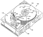
図1は、本発明の諸態様が有用なディスク・ドライブ100の斜視図である。ディスク・ドライブ100は、基部102及び上部カバー(図示せず)を備えたハウジングを含む。ディスク・ドライブ100は、ディスク・クランプ108によってスピンドル・モータ(図示せず)上に取り付けられたディスク・パック106を更に含む。ディスク・パック106は、複数の個々のディスクを含み、それらは、中心(スピン)軸109の周りで方向107に共回転することができるように取り付けられている。各ディスク表面には、関連するディスク・ヘッド・スライダ110があり、ディスク・ヘッド・スライダ110は、ディスク表面と情報のやりとりをすることができるようにディスク・ドライブ100に取り付けられている。図1に示す実施例では、スライダ110がサスペンション112によって支持され、サスペンション112は、アクチュエータ116のトラック・アクセス・アーム114に取り付けられている。図1に示すアクチュエータは、回転可動コイル・アクチュエータとして知られるタイプのものであり、全体的に符号118で示すボイス・コイル・モータ(VCM)を含む。ボイス・コイル・モータ118は、アクチュエータ116とその取り付けられたヘッド110を旋回軸120の周りで、ヘッド110をディスク内径124とディスク外径126の間の弓形経路122に沿って所望のデータ・トラックの上に位置決めするように、回転させる。ボイス・コイル・モータ118は、ヘッド110及びホスト・コンピュータ(図示せず)によって生成される信号に基づいて、サーボ電子回路130により駆動される。
FIG. 1 is a perspective view of a
図2は、千鳥配置(stagger)モード垂直記録メディアで使用する、一例示的読取り/書込みヘッド200を示す。「千鳥配置モード垂直記録メディア」という用語は、本願では、記録メディア・アイランドが、記録トラック内の複数の半径のところで千鳥状位置に配置されるパターンド・メディアを意味する。例えば、2つの半径のところにメディア・アイランドを有する記録トラックでは、メディア・アイランドが円形又はうずまき形のトラック上の2つの半径のところに、交互に配置される。
FIG. 2 shows an exemplary read / write
読取り/書込みヘッド200は、スライダ(図2には図示せず)のより大きなエア・ベアリング面の一部分であるエア・ベアリング面202を備える。読取り/書込みヘッド200の書込み部分が、読取り/書込みヘッド200の前側にシールド204を備える。シールド204は、エア・ベアリング面202の一部分であるシールド面206を備える。シールド面206は、エア・ベアリング層を隔てて磁気メディア(図2には図示せず)と対面する。
The read / write
書込み磁極208が、エア・ベアリング面202の一部分である書込み磁極面210を備える。書込み磁極面210は、エア・ベアリング層を隔てて磁気メディアと対面する。書込み磁極面210は、広い方の後縁212から狭い方の前縁214まで延在する、ほぼ四辺形のテーパ形状を有する。
The
読取り/書込みヘッド200の書込み部分は、ギャップ層216を備える。書込みコイル218が、ギャップ層216に埋め込まれる。書込みコイル218中を流れる電流が書込み磁界を誘起させ、それが書込み磁極208を通過し、シールド204を通過し、磁気メディアを通過する外部経路を通過する。書込み磁極面210は、シールド面206よりもかなり狭い表面積を有する。書込み磁極208が磁気メディア上にデータを書き込むことができるように、磁束密度がより狭い書込み磁極面210において十分に集束される。磁束密度は、シールド204が磁気メディア上にデータを書き込むことができないように、より広いシールド面206において十分に拡散される。書込み磁極面210のテーパ状四辺形形状が、書込み磁界220の類似のテーパ状四辺形書込み磁界形状218を画定し、それが、エア・ベアリング層を横切って磁気メディアに印加される。書込み磁界形状218は、磁気メディア上のトラック幅にほぼ対応する書込み幅226を有する。書込み幅226は、千鳥配置モード記録メディア上の異なるディスク半径のところにある複数の千鳥状アイランドを交互に読み取るのに十分なほど広い。書込み幅226は、ヘッド200の長手方向書込み磁界軸228に対して、ほぼ直角である。長手方向書込み磁界軸228は、書込み磁界220に隣接する磁気メディアのスピン運動軸230と、可変な鋭角232で位置合わせされる。しかし、軸228と軸230の位置関係は、ヘッド200が(図1のボイス・コイル・モータ118などの)ボイス・コイル・モータの制御下でメディア表面を横切って移動する際に変化する。軸228と軸230の間の可変な鋭角232をここで、スキュー角232と呼ぶ。スキュー角232は、長手方向書込み軸228と、メディア表面上のトラックとの位置ずれの尺度である。スキュー角232は、メディア表面に平行な平面内で測定される。
The write portion of the read / write
読取り/書込みヘッド200は、シールド204、205間に、磁気抵抗読取り素子222を備える。読取り素子222は、エア・ベアリング面202の一部分である読取り素子面224を備える。読取り素子面224は、エア・ベアリング層202を隔てて磁気メディアと対面する。読取り素子222は、磁気メディアからデータを読み取る。読取り素子222は、千鳥配置モード記録メディア上の異なる半径のところにある複数の千鳥状アイランドを交互に読み取るのに十分なほど広い。
Read / write
パターンド記録メディアは、メディア表面上で互いに離隔された磁性アイランドのアレイを備える。パターンド・アイランド間の間隔は、読取り/書込みヘッドが飛び越える平滑な表面をもたらすように、非メディア材料で埋められる。非メディア材料は、磁性アイランドを互いに離隔する。アイランド間の円周方向間隔は、トラックの長さに沿って円周方向に測定される。磁性アイランドは、円形でも、楕円形でも、別の形状でもよい。1ビットのデータが、アイランドのうち1つ又は複数上に記録される。千鳥配置モード・メディアでは、アイランドが、トラック内の単一の半径に沿って位置合わせされるのではなく、トラック内の異なる半径のところに交互に千鳥配置される。トラック内のアイランドは、メディア・スピン軸(例えば図1の軸109)から互いに異なる半径のところにあり、千鳥配置間隔によって、円周方向にも千鳥配置される。各トラックは、それ自体の千鳥配置間隔を有する。トラック内では、千鳥配置間隔が小さい方の半径上にあるアイランドから大きい方の半径上にある連続するアイランドに向かうのか、それとも大きい方の半径上にあるアイランドから小さい方の半径上にある連続するアイランドに向かうのかに関わらず、千鳥配置間隔をトラック一周にわたってずっと固定値とすることができる。しかし、そのような固定の千鳥配置間隔にすると、スキュー角がメディア表面の内径又は外径に向かって増大するにつれて、位置ずれの増大が生じることが分かっている。
Patterned recording media comprises an array of magnetic islands spaced apart from each other on the media surface. The spacing between the patterned islands is filled with non-media material to provide a smooth surface that the read / write head jumps over. Non-media material separates the magnetic islands from each other. The circumferential spacing between islands is measured circumferentially along the length of the track. The magnetic island may be circular, elliptical, or another shape. One bit of data is recorded on one or more of the islands. In staggered mode media, islands are staggered alternately at different radii in the track, rather than aligned along a single radius in the track. The islands in the track are at different radii from the media spin axis (eg,
一態様では、同心データ・トラックが、円形トラックを備える(図7)。別の態様では、同心データ・トラックが、うずまきトラック(図8)の同心部分を備える。高密度メディア表面上には、非常に多数の複数の同心データ・トラックがあることが理解されよう。複数の記録トラックは、下にあるディスク基板表面上に配設される。各トラックは、(図2の書込み幅228などの)ヘッドの書込み幅によって定義されるトラック幅を有する。各トラックは、トラックの円周方向の長さに沿った複数の半径のところに連続して又は交互に配列された、パターンド・メディア・アイランドを含む。
In one aspect, the concentric data track comprises a circular track (FIG. 7). In another aspect, the concentric data track comprises a concentric portion of the spiral track (FIG. 8). It will be appreciated that there are a large number of multiple concentric data tracks on a high density media surface. A plurality of recording tracks are disposed on the underlying disk substrate surface. Each track has a track width defined by the write width of the head (such as
書込み時間間隔中、(図2の読取り/書込みヘッド200などの)読取り/書込みヘッドが、(図2の書込み磁界形状218などの)書込み磁界形状を有する(図2の書込み磁界220などの)書込み磁界を、書込みのために選択されたトラックに供給する。(図1のボイス・コイル・モータ118などの)ボイス・コイル・モータが、書込み磁界形状を、選択されたトラック上に位置決めする。書込み磁界形状は、ボイス・コイル・モータによって、円(又はうずまき)弧形状を有するヘッド経路に沿って位置決めされる。ヘッド経路は、ボイス・コイル・モータがその回転軸の周りで回転することにより定義される。
During a write time interval, a read / write head (such as read /
トラック軸にヘッド経路との交点で接する接線が、(図2のスピン運動軸230などの)スピン運動軸を有する。(図2のスキュー角232などの)スキュー角は、トラック上の中間径付近でほぼゼロである。スキュー角は、内径付近及び外径付近で、最大スキュー角に増大する。スキュー角は一般に、メディア・ディスクの内径から外径までで、約+18度から−18度の範囲にわたって変化する。
A tangent tangent to the track axis at the intersection with the head path has a spin motion axis (such as the
アイランドを連続して又は交互に千鳥配置すると、読取り/書込みヘッドは、中間径付近でのみ、ほぼ等しく離隔された時間間隔で、千鳥状アイランドに対してデータを連続して書き込み、且つ読み取ることが可能になる。中間径のところでスキュー角がほぼゼロなので、アイランドの千鳥配置は、書込み部の後縁と対称に位置合わせされる。アイランドからの読取り信号のタイミングは、図3Aに示すように一様である。 When the islands are staggered sequentially or alternately, the read / write head can continuously write and read data to and from the staggered islands at approximately equally spaced time intervals only near the intermediate diameter. It becomes possible. Since the skew angle is almost zero at the intermediate diameter, the staggered arrangement of islands is aligned symmetrically with the trailing edge of the writing section. The timing of the read signal from the island is uniform as shown in FIG. 3A.
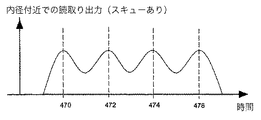
アイランドを千鳥配置すると、読取り/書込みヘッドは、内径(又は外径)付近で、著しく非一様に離隔された時間間隔で、連続して千鳥配置されたアイランドに対してデータを書き込み、且つ読み取ることが可能になる。内径(又は外径)付近でスキュー角がほぼ最大になるので、アイランドの千鳥配置は、書込み部の後縁と非対称に位置合わせされる。内径又は外径付近のアイランドからの読取り信号のタイミングは、図3Bに示すように一様ではない。 When the islands are staggered, the read / write head writes and reads data to the staggered islands in a substantially non-uniformly spaced time interval near the inner diameter (or outer diameter). It becomes possible. Since the skew angle is almost maximized near the inner diameter (or outer diameter), the staggered arrangement of islands is asymmetrically aligned with the trailing edge of the writing section. The timing of read signals from islands near the inner or outer diameter is not uniform as shown in FIG. 3B.
スキュー関数で修正されないアイランド位置を有するパターンド「千鳥配置モード」ビット・パターン・メディアの場合、ディスク半径の関数としてスキュー角が変化すると、大きい方のスキュー角において、望ましくない読取り及び書込みの変調が生じる。スキュー角は、書込み中の誤りと読取り中の誤りのどちらも生じさせる。この誤りにより、大きい方のスキュー角において、チャネル・ビット誤り率(BER)が悪化する。 For patterned “staggered mode” bit pattern media with island positions that are not corrected by the skew function, changing the skew angle as a function of disk radius will result in undesirable read and write modulation at the larger skew angle. Arise. The skew angle causes both an error during writing and an error during reading. This error degrades the channel bit error rate (BER) at the larger skew angle.
図3Aは、中間径のところのトラック内の、連続する円周方向部分340、342、344、346にあるアイランドを読み取ることによって発生するパルスのタイミングを表す。パルスは、一様に離隔され、一様なパルス幅を有する。図3Aのパルスには、変調歪みがない。
FIG. 3A represents the timing of the pulses generated by reading the islands in successive
図3Bは、メディア・ディスクの内径又は外径のところのトラック内の、連続する円周方向部分350、352、354、356にあるアイランドを読み取ることによって発生するパルスのタイミングを表す。図3Bのパルスは、不規則に離隔され、非一様なパルス幅を有する。図3Bのパルスは、変調歪みを有する。変調歪みに伴う問題は、中間径のところで最小であり、スキュー角が増大するにつれて悪化し、内径及び外径のところで最悪になる。スキューによる変調歪みに伴う問題は、図4A及び5に示す実施例において説明するように、トラックの長さに沿った円周方向間隔を、トラック半径のスキュー関数として調整することによって、実質的に解決される。
FIG. 3B represents the timing of pulses generated by reading islands in successive
したがって、スキュー角に伴って変化しないアイランド間の間隔を有する、千鳥状パターンド・メディアに伴う問題がある。スキュー角の関数としての読取り及び書込みタイミングのばらつきがあると、読取り及び書込みチャネルに更なる負荷がかかり、スキュー角が増大すると、ビット誤り率が悪化する。これらの問題は、図4A、4B、4C、5に関連して以下に説明する態様において克服される。 Thus, there is a problem with staggered patterned media having an inter-island spacing that does not change with skew angle. Variations in read and write timing as a function of skew angle place additional loads on the read and write channels, and bit error rates worsen as the skew angle increases. These problems are overcome in the manner described below in connection with FIGS. 4A, 4B, 4C, and 5.
図4Aは、パターンド記録メディア400を示す。パターンド記録メディア400は、メディア・スピン軸496の周りでスピンする。パターンド記録メディア400は、うずまきトラック(図8)又は同心トラック(図7)を備えることができる。ボイス・コイル・モータ(図4Aには図示せず)が、読取り/書込みヘッドをパターンド記録メディア400上に位置決めするように、ボイス・コイル・モータ旋回軸498の周りで旋回する。パターンド記録メディア400は、メディア・ディスクの中間半径付近にトラック402を備え、そこでは、書込み磁界形状404及び読取り部表面形状406が、スピン運動軸408にほぼ垂直に位置合わせされる。スピン運動軸408は、図示のように、トラック軸に接して位置合わせされる。パターンド記録メディア400は、トラック402内に、記録アイランド460、462、464、466を備え、それらは、異なる半径418、419のところに交互に配置される。ゼロ・スキュー角にあるトラック402では、連続するアイランド間の円周方向間隔が、実質的に固定される。
FIG. 4A shows a
パターンド記録メディア400は、メディア・ディスクの内側半径付近にトラック432を備え、そこでは、書込み磁界形状434及び読取り部表面形状436が、スピン運動軸438に垂直に位置合わせされない。スピン運動軸438は、図示のように、トラック軸に接して位置合わせされる。パターンド記録メディア400は、トラック432内に、複数の記録アイランド470、472、474、476、478を備え、それらは、異なる半径448、449上に位置する。アイランド472、474間の円周方向間隔492(太線)は、アイランド474、476間の円周方向間隔490(太線)とは実質的に異なる。
The patterned
円周方向間隔は、(スキュー角がゼロであり、円周方向間隔が固定されている)トラック402と、(スキュー角が大きく、円周方向間隔490、492が大幅に異なる)トラック432との間で変化する。円周方向間隔は、スキュー角の関数として変化する。
Circumferential spacing is between track 402 (with zero skew angle and fixed circumferential spacing) and track 432 (with large skew angle and significantly different
スキュー関数は、複数の記録メディア・アイランドからなるグループにアクセスするヘッドのスキュー角の変化を補償する。アイランドの各グループの位置合せは、アイランドのグループと読取り/書込みパターンとの固定のタイミング関係を維持するように補償される。補償は、中間径において最小であり、トラックごとに、そのトラックが中間径からどれだけ遠く離れているかに応じて、より大きな補償量に増大する。 The skew function compensates for a change in the skew angle of a head that accesses a group of recording media islands. The alignment of each group of islands is compensated to maintain a fixed timing relationship between the group of islands and the read / write pattern. Compensation is minimal at the intermediate diameter and increases from track to track with a larger amount of compensation depending on how far the track is from the intermediate diameter.
アイランドを千鳥配置すると、読取り/書込みヘッドが、図4Aに示す中間径のところでのみ、ほぼ等しく離隔された時間間隔で、千鳥状アイランド460、462、464、466に対してデータを書き込み、且つ読み取ることが可能になる。中間径のところではスキュー角がほぼゼロなので、アイランド460、462、464、466の千鳥配置は、書込み部の後縁に対称に位置合わせされる。アイランド460、462、464、466からの読取り信号のタイミングは、図4Bに示すように一様である。
When the islands are staggered, the read / write head writes and reads data to and from the staggered
アイランドを千鳥配置すると、読取り/書込みヘッドが、内径付近で、著しく非一様な距離間隔ではあるが、図4Cに示すように、固定の離隔された時間間隔で、千鳥状アイランド470、472、474、476に対してデータを書き込み、且つ読み取ることが可能になる。スキュー角が内径付近でほぼ最大になるので、アイランド470、472、474、476の千鳥配置は、書込み部の後縁と非対称に位置合わせされる。アイランド470、472、474、476からの読取り信号のタイミングは、図4Cに示すように一様である。
When the islands are staggered, the read / write heads are at a substantially non-uniform distance interval near the inner diameter, but at fixed spaced time intervals, as shown in FIG. 4C, the staggered
記録ヘッドが記録トラックの長さに沿って移動する際にヘッドが第1及び第2のアイランドに連続してアクセスするように、記録トラックの長さに沿った異なる第1及び第2の半径のところに、複数の第1及び第2のパターンド・メディア・アイランドは交互に配置される。トラックの長さに沿った、連続する第1のアイランドと第2のアイランドとの間の間隔は、メディア・スピン軸からのトラック半径のスキュー関数として変化する。読取り出力のタイミングは、図4B、4Cのどちらにおいても、時間の面で一様である。スキュー角の関数としてアイランドを千鳥配置すると、読取り及び書込みタイミングのばらつきが回避され、スキュー角に実質的に無関係な一様に低いビット誤り率がもたらされる。「スキュー関数」という用語は、本願では、メディア・アイランドの円周方向位置を変化させる関数を意味し、変化する円周方向位置が連続してアクセスされるメディア・アイランド間の時間間隔のばらつきを低減する。スキュー関数は、スキュー角の変化を補償するように、メディア・アイランドの円周方向位置を調整する。 With different first and second radii along the length of the recording track so that the head continuously accesses the first and second islands as the recording head moves along the length of the recording track. However, the plurality of first and second patterned media islands are alternately arranged. The spacing between successive first and second islands along the length of the track varies as a skew function of the track radius from the media spin axis. The read output timing is uniform in terms of time in both FIGS. 4B and 4C. Staggering islands as a function of skew angle avoids read and write timing variability and results in a uniformly low bit error rate that is substantially independent of skew angle. The term “skew function” as used herein refers to a function that changes the circumferential position of a media island, and the variation in time interval between media islands in which the changing circumferential position is continuously accessed. To reduce. The skew function adjusts the circumferential position of the media island to compensate for changes in the skew angle.
磁性アイランドが図5においては各トラック内で3つの異なる半径のところに配置されていることを除き、パターンド・メディア400に類似する、パターンド・メディア500を図5は示す。パターンド記録メディア500は、うずまきトラック(図8)又は同心トラック(図7)を備えることができる。ヘッドの読取り幅及び書込み幅は、3つの異なる半径のところでアイランドに連続してアクセスするのに十分なほど広い。トラックの長さに沿った、連続する第1、第2及び第3のアイランド間の間隔は、メディア・スピン軸596からのトラック半径のスキュー関数として変化する。読取り出力のタイミングは、時間の面で一様である。パターンド記録メディア500は、メディア・スピン軸596の周りでスピンする。ボイス・コイル・モータ(図5には図示せず)が、読取り/書込みヘッドをパターンド記録メディア500上に位置決めするように、ボイス・コイル・モータ旋回軸598の周りで旋回する。
FIG. 5 shows a patterned
スキュー角がほぼゼロになる中間径付近で、複数のパターンド・メディア・アイランド502、504、506、508、510、512が第1の記録トラック501の長さに沿った第1の半径514、第2の半径516、及び第3の半径518のところに連続して配置され、記録ヘッドが記録トラックの長さに沿って移動する際にヘッドがアイランド502、504、506、508、510、512に連続してアクセスする。トラック501上でスキュー角がほぼゼロなので、これらのアイランドは、固定の円周方向間隔で離隔される。例えば、アイランド502、504間の円周方向間隔は、アイランド506と508の間の円周方向間隔と同じである。中間径のところでスキュー角がほぼゼロなので、中間径における円周方向間隔は、一様にすることができる。書込み磁界形状の後縁503が、中間径のところで、(軸596から広がる)スピン半径ライン599と実質的に平行である。メディア・アイランドを連続して読み取る、又は書き込むタイミングは、アイランド間に一様な円周方向時間間隔を有する。中間径のところでスキュー角はほぼゼロであり、中間アイランドの連続する読取り又は書込み間の時間間隔は、同様に一様である。
A plurality of patterned
記録ヘッドが記録トラック521の長さに沿って移動する際にヘッドがアイランド522、523、524、526、528、530、532に連続してアクセスするように、スキュー角がほぼその最大になる内径付近で、複数のパターンド・メディア・アイランド522、523、524、526、528、530、532が第2の記録トラック521の長さに沿った第1の半径540、第2の半径542、及び第3の半径544のところに、連続して配置される。トラック521上でスキュー角がほぼ最大なので、これらのアイランドは、変化する円周方向間隔で離隔される。例えば、アイランド522、523間の円周方向間隔594は、アイランド523と524の間の円周方向間隔592と同じである。しかし、アイランド524、526間の円周方向間隔590は、間隔592、594とは異なる。
As the recording head moves along the length of the
内径のところでスキュー角がほぼ最大になるので、内径(及び外径)における円周方向間隔は、一様にすることができない。内径のところで、書込み磁界形状の後縁546が、スピン半径ライン597に対して実質的にスキュー又は斜めにされる。しかし、メディア・アイランドを連続して読み取る、又は書き込むタイミングは、アイランド間に一様な時間間隔を有する。変化する円周方向間隔により、トラック521上に一様なタイミング間隔をもたらすように、スキューが補償される。トラックの長さに沿った、連続する第1、第2、及び第3のアイランド間の間隔は、メディア・スピン軸からのトラック半径のスキュー関数として変化する。読取り出力のタイミングは、時間の面で一様である。
Since the skew angle is almost maximized at the inner diameter, the circumferential interval at the inner diameter (and the outer diameter) cannot be made uniform. At the inner diameter, the trailing
図6は、スキュー関数によって調整されていないビット・パターンド・メディアの場合の、スキュー角の関数としてのビット誤り率(BER)のグラフを示す。図6から分かるように、(図6において丸で表される)ビット誤り率は、ゼロ・スキュー角における最小値から、スキュー角の絶対値が増大するにつれてますます増大する誤り率は増大する。スキュー角の増大に伴ってますます悪化するビット誤り率のパターンは、スキュー関数に従って間隔が変化する、説明したビット・パターンド・メディアを使用することにより回避される。間隔がスキュー関数によって調整されたビット・パターンド・メディアの場合のビット誤り率は、ほぼ平坦である(図6において点線で表されている)。 FIG. 6 shows a graph of bit error rate (BER) as a function of skew angle for bit patterned media not adjusted by a skew function. As can be seen from FIG. 6, the bit error rate (represented by a circle in FIG. 6) increases from the minimum value at the zero skew angle to an increasing error rate as the absolute value of the skew angle increases. Increasing bit error rate patterns with increasing skew angle are avoided by using the described bit patterned media whose spacing varies according to the skew function. The bit error rate in the case of bit patterned media whose spacing is adjusted by a skew function is substantially flat (represented by a dotted line in FIG. 6).
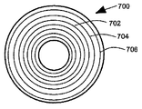
図7は、同心トラック702、704、706など、複数の同心トラックを含む、メディア・ディスク700を示す。
FIG. 7 shows a
図8は、うずまきトラック802を含むメディア・ディスク800を示す。
FIG. 8 shows a
トラック内の異なる半径のところのアイランドを、スキュー角の絶対値が増大するにつれてそれらの半径がますます互いにより近くなるように、トラックに対して直角に移動させることもできる。例えば、連続するアイランドがトラック軸に対して45度の角度の軸にほぼ沿って配列された、2トラック千鳥配置モードの場合、下方のトラック方向への相対位置移動量は、約δL=l0sin(θ)であり、相対クロス・トラック縮小(cross track contraction)は、約δW=l0(1−cos2(θ))である。ただしl0は、標準ピッチのアイランド・サイズであり、これはゼロ・スキューにおけるアイランド間隔の約1/√2であり、θはスキュー角である。 It is also possible to move islands at different radii in the track at right angles to the track so that their radii become increasingly closer to each other as the absolute value of the skew angle increases. For example, in the two-track staggered arrangement mode in which consecutive islands are arranged substantially along an axis at an angle of 45 degrees with respect to the track axis, the relative position movement amount in the lower track direction is about δL = l 0. sin (θ) and the relative cross-track reduction is approximately δW = l 0 (1-cos 2 (θ)). Where l 0 is the standard pitch island size, which is approximately 1 / √2 of the island spacing at zero skew, and θ is the skew angle.
一態様によれば、アイランドの1つが、記憶メディアの単一粒子(single grain)を備える。別の態様によれば、記録メディアが、CoPt、CoPtB、FePt、CoPtP、又は他の適切な磁気メディア材料を含む。更に別の態様によれば、アイランドが、25ナノメートル以下の主径を有する。更に別の態様によれば、アイランド間の間隔を埋める非磁性材料が、Al2O3、SiO、SiN、HfO2、WOx、NbO、C、又は他の適切な非磁性材料を含んでよい。更に別の態様によれば、アイランド間の分離(すなわち非磁性材料の幅)が、1〜30ナノメートルの範囲でよい。更に別の態様によれば、隣接するアイランド間の中心間距離が、10〜50ナノメートルの範囲内でよい。 According to one aspect, one of the islands comprises a single grain of storage media. According to another aspect, the recording media comprises CoPt, CoPtB, FePt, CoPtP, or other suitable magnetic media material. According to yet another aspect, the island has a major diameter of 25 nanometers or less. According to yet another aspect, the non-magnetic material that fills the spacing between islands may include Al 2 O 3 , SiO, SiN, HfO 2 , WO x , NbO, C, or other suitable non-magnetic material. . According to yet another aspect, the separation between islands (ie, the width of the non-magnetic material) may be in the range of 1-30 nanometers. According to yet another aspect, the center-to-center distance between adjacent islands may be in the range of 10-50 nanometers.
一態様では、パターンド記録メディアが磁気記録メディアを備える。別の態様では、パターンド記録メディアが光メディアを備える。更に別の態様では、パターンド記録メディアが光磁気メディアを備える。これらの各態様では、トラックの長さに沿った、連続する第1のアイランドと第2のアイランドとの間の間隔が、トラック半径のスキュー関数として変化する。 In one aspect, the patterned recording medium comprises a magnetic recording medium. In another aspect, the patterned recording medium comprises an optical medium. In yet another aspect, the patterned recording medium comprises a magneto-optical medium. In each of these aspects, the spacing between successive first islands and second islands along the length of the track varies as a skew function of the track radius.
以上、本発明のさまざまな態様の多数の特性及び利点を、本発明のさまざまな態様の構造及び機能の詳細と共に、先の説明において述べてきたが、本開示は例示的なものにすぎず、本発明の原理内で、添付の特許請求の範囲がそれを用いて表現された用語のもつ、幅広い一般的な意味によって示される全範囲まで、特に各部分の構造及び配列の事柄に詳細に変更を加えることができることを理解されたい。例えば、特定の要素は、本発明の範囲及び精神から逸脱することなく、実質的に同じ機能性を維持しながら、パターンド・メディア・システムの特定の適用分野に応じて異なってよい。更に、本明細書で述べた好ましい態様は、回転パターンを備えたディスク・ドライブ・システムを対象としているが、本発明の教示は、本発明の範囲及び精神から逸脱することなく、スキューがビット誤り率に影響を及ぼす他のディスク走査パターンに適用できることが、当業者には理解されよう。それらの態様は、デカルト座標系に対してスキューするヘッド又はプローブを用いて、デカルト座標系方向に向けられたメディア・パターンの場合に、有用である。 While numerous features and advantages of various aspects of the invention have been described in the foregoing description, together with details of the structure and function of the various aspects of the invention, the disclosure is illustrative only, Within the principles of the present invention, the appended claims are modified in detail to the full extent indicated by the broad general meaning of the terms expressed therewith, in particular to the structure and arrangement of the parts. It should be understood that can be added. For example, the particular elements may vary depending on the particular application area of the patterned media system while maintaining substantially the same functionality without departing from the scope and spirit of the invention. Further, while the preferred embodiment described herein is directed to a disk drive system with a rotational pattern, the teachings of the present invention are subject to bit errors without departing from the scope and spirit of the present invention. One skilled in the art will appreciate that it can be applied to other disk scan patterns that affect rate. These aspects are useful for media patterns that are oriented in the Cartesian coordinate system direction using a head or probe that skews relative to the Cartesian coordinate system.
100 ディスク・ドライブ
106 ディスク・パック
109 中心(スピン)軸
110 ディスク・ヘッド・スライダ、ヘッド
116 アクチュエータ
118 ボイス・コイル・モータ
120 旋回軸
124 ディスク内径
126 ディスク外径
200 読取り/書込みヘッド
202 エア・ベアリング面、エア・ベアリング層
204 シールド
205 シールド
206 シールド面
208 書込み磁極
210 書込み磁極面
212 後縁
214 前縁
218 書込みコイル、書込み磁界形状
220 書込み磁界
222 磁気抵抗読取り素子
224 読取り素子面
226 書込み幅
228 長手方向書込み磁界軸
230 スピン運動軸
232 可変な鋭角、スキュー角
400 パターンド記録メディア
402 トラック
404 書込み磁界形状
406 読取り部表面形状
408 スピン運動軸
418 半径
419 半径
432 トラック
434 書込み磁界形状
436 読取り部表面形状
438 スピン運動軸
448 半径
449 半径
460 記録アイランド、千鳥状アイランド
462 記録アイランド、千鳥状アイランド
464 記録アイランド、千鳥状アイランド
466 記録アイランド、千鳥状アイランド
470 記録アイランド、千鳥状アイランド
472 記録アイランド、千鳥状アイランド
474 記録アイランド、千鳥状アイランド
476 記録アイランド、千鳥状アイランド
490 円周方向間隔
492 円周方向間隔
496 メディア・スピン軸
500 パターンド・メディア、パターンド記録メディア
501 第1の記録トラック
502 パターンド・メディア・アイランド
503 後縁
504 パターンド・メディア・アイランド
506 パターンド・メディア・アイランド
508 パターンド・メディア・アイランド
510 パターンド・メディア・アイランド
512 パターンド・メディア・アイランド
514 第1の半径
516 第2の半径
518 第3の半径
521 第2の記録トラック
522 パターンド・メディア・アイランド
523 パターンド・メディア・アイランド
524 パターンド・メディア・アイランド
526 パターンド・メディア・アイランド
528 パターンド・メディア・アイランド
530 パターンド・メディア・アイランド
532 パターンド・メディア・アイランド
540 第1の半径
542 第2の半径
544 第3の半径
546 後縁
590 円周方向間隔
592 円周方向間隔
594 円周方向間隔
596 メディア・スピン軸
597 スピン半径ライン
598 ボイス・コイル・モータ旋回軸
599 スピン半径ライン
700 メディア・ディスク
800 メディア・ディスク
100 disk drive 106 disk pack 109 central (spin) shaft 110 disk head slider, head 116 actuator 118 voice coil motor 120 pivot axis 124 disk inner diameter 126 disk outer diameter 200 read / write head 202 air bearing surface , Air bearing layer 204 shield 205 shield 206 shield surface 208 write magnetic pole 210 write magnetic pole surface 212 trailing edge 214 front edge 218 write coil, write magnetic field shape 220 write magnetic field 222 magnetoresistive read element 224 read element surface 226 write width 228 longitudinal direction Write magnetic field axis 230 Spin motion axis 232 Variable acute angle, skew angle 400 Patterned recording medium 402 Track 404 Write magnetic field shape 406 Reading unit Surface shape 408 Spin motion axis 418 Radius 419 Radius 432 Track 434 Write magnetic field shape 436 Reading unit surface shape 438 Spin motion axis 448 Radius 449 Radius 460 Recording island, staggered island 462 Recording island, staggered island 464 Recording island, staggered island 466 Recording Island, Staggered Island 470 Recording Island, Staggered Island 472 Recording Island, Staggered Island 474 Recording Island, Staggered Island 476 Recording Island, Staggered Island 490 Circumferential Interval 492 Circumferential Interval 496 Media Spin Axis 500 Patterned media, Patterned recording media 501 First recording track 502 Patterned media island 503 Trailing edge 504 Pa Routed media island 506 Patterned media island 508 Patterned media island 510 Patterned media island 512 Patterned media island 514 First radius 516 Second radius 518 Third radius 521 First 2 recording tracks 522 Patterned Media Island 523 Patterned Media Island 524 Patterned Media Island 526 Patterned Media Island 528 Patterned Media Island 530 Patterned Media Island 532 Patterned Media Island Media Island 540 First Radius 542 Second Radius 544 Third Radius 546 Trailing Edge 590 Circumferential Spacing 592 Circumferential Spacing 594 Circumferential Spacing 59 Media spin shaft 597 spin radius line 598 voice coil motor pivot 599 spin radius line 700 Media disk 800 media disks
Claims (11)
記録ヘッドが記録トラックの長さに沿って移動する際に前記記録ヘッドが連続して個別にアクセスするように、前記記録トラックの長さに沿った異なる第1及び第2の半径のところに連続して配置された複数の第1及び第2のパターンド・メディア・アイランドを備え、
前記記録トラックの長さに沿った、前記連続する第1のアイランドと第2のアイランドとの間の前記記録トラックを横切る方向の間隔が、トラック半径のスキュー関数として変化し、
連続する第1のアイランドと第2のアイランドとの間の前記記録トラックの長さに沿った間隔が、より短い間隔とより長い間隔を交互に繰り返す、記録メディア。 A recording medium,
To access individually the recording head when the recording head moves along the length of the recording track is continuously communicated at the along the length different from the first and second radii of said recording track comprising first and second patterned media islands of several disposed continue to,
The spacing across the recording track between the successive first and second islands along the length of the recording track varies as a skew function of the track radius;
A recording medium in which a distance along the length of the recording track between a continuous first island and a second island alternately repeats a shorter distance and a longer distance.
記録ヘッドが記録トラックの長さに沿って移動する際に前記記録ヘッドが第1及び第2のアイランドに連続して個別にアクセスするように、複数の第1及び第2のパターンド・メディア・アイランドを前記記録トラックの長さに沿った異なる第1及び第2の半径のところに連続して配置すること、並びに
前記記録トラックの長さに沿った、連続する第1のアイランドと第2のアイランドとの間の前記記録トラックを横切る方向の間隔を、トラック半径のスキュー関数として変化させることを含み、
連続する第1のアイランドと第2のアイランドとの間の前記記録トラックの長さに沿った間隔が、より短い間隔とより長い間隔を交互に繰り返す、方法。 A method for formalizing patterned recording media,
A plurality of first and second patterned media such that the recording head sequentially and individually accesses the first and second islands as the recording head moves along the length of the recording track. placing consecutive to the islands at a radius along a length different from the first and second of said recording track, and along the length of the recording track, the first island and the second continuous Varying the distance across the recording track between the island and the island as a skew function of the track radius,
A method wherein the spacing along the length of the recording track between successive first and second islands alternates between shorter and longer intervals.
記録トラックの長さに沿った異なる第1及び第2の半径のところに、個別アクセスのために連続して配置された、複数の第1及び第2のパターンド・メディア・アイランドを備え、前記記録トラックの長さに沿う連続する第1のアイランドと第2のアイランドとの間の前記記録トラックを横切る方向の間隔が、トラック半径のスキュー関数として変化し、
連続する第1のアイランドと第2のアイランドとの間の前記記録トラックの長さに沿った間隔が、より短い間隔とより長い間隔を交互に繰り返す、パターンド記録メディア。 A patterned recording medium,
A plurality of first and second patterned media islands arranged sequentially for separate access at different first and second radii along the length of the recording track; The spacing across the recording track between successive first and second islands along the length of the recording track varies as a skew function of the track radius;
A patterned recording medium, wherein an interval along a length of the recording track between a continuous first island and a second island alternately repeats a shorter interval and a longer interval.
Applications Claiming Priority (2)
| Application Number | Priority Date | Filing Date | Title |
|---|---|---|---|
| US11/870,858 | 2007-10-11 | ||
| US11/870,858 US7864470B2 (en) | 2007-10-11 | 2007-10-11 | Patterned media with spacings adjusted by a skew function |
Publications (3)
| Publication Number | Publication Date |
|---|---|
| JP2009110642A JP2009110642A (en) | 2009-05-21 |
| JP2009110642A5 JP2009110642A5 (en) | 2011-08-18 |
| JP5453668B2 true JP5453668B2 (en) | 2014-03-26 |
Family
ID=40533945
Family Applications (1)
| Application Number | Title | Priority Date | Filing Date |
|---|---|---|---|
| JP2008263414A Expired - Fee Related JP5453668B2 (en) | 2007-10-11 | 2008-10-10 | Patterned media with spacing adjusted by skew function |
Country Status (3)
| Country | Link |
|---|---|
| US (1) | US7864470B2 (en) |
| JP (1) | JP5453668B2 (en) |
| SG (1) | SG152144A1 (en) |
Families Citing this family (11)
| Publication number | Priority date | Publication date | Assignee | Title |
|---|---|---|---|---|
| JP4728892B2 (en) * | 2006-06-30 | 2011-07-20 | 株式会社東芝 | Magnetic recording medium and method for manufacturing the same |
| JP4724060B2 (en) * | 2006-06-30 | 2011-07-13 | 株式会社東芝 | Magnetic disk unit |
| US9495996B2 (en) * | 2007-06-29 | 2016-11-15 | Seagate Technology, Llc | Writer with increased write field |
| JP2010044833A (en) * | 2008-08-14 | 2010-02-25 | Toshiba Storage Device Corp | Method of detecting head position and recording medium drive unit |
| US8455117B2 (en) * | 2009-03-04 | 2013-06-04 | Seagate Technology Llc | Bit-patterned stack with antiferromagnetic shell |
| JP5182275B2 (en) * | 2009-11-18 | 2013-04-17 | 富士電機株式会社 | Method for manufacturing magnetic recording medium |
| US8824092B2 (en) * | 2010-11-08 | 2014-09-02 | Seagate Technology Llc | Skew compensation signal |
| JP5335983B2 (en) * | 2011-10-05 | 2013-11-06 | Hoya株式会社 | Glass substrate for magnetic disk and magnetic recording medium |
| US8824101B2 (en) | 2012-10-08 | 2014-09-02 | Seagate Technology Llc | Write pole tip with trailing edge recess |
| US9666212B2 (en) | 2012-12-05 | 2017-05-30 | Seagate Technology Llc | Writer with protruded section at trailing edge |
| US8995073B1 (en) | 2013-03-14 | 2015-03-31 | Seagate Technology Llc | Data storage mediums and devices having bit patterned media |
Family Cites Families (19)
| Publication number | Priority date | Publication date | Assignee | Title |
|---|---|---|---|---|
| JPH0554302A (en) * | 1991-08-26 | 1993-03-05 | Fuji Electric Co Ltd | Magnetic recorder |
| JPH0845189A (en) * | 1994-07-29 | 1996-02-16 | Fujitsu Ltd | Disk device and format preparing method for disk medium |
| US6778343B2 (en) * | 1998-03-25 | 2004-08-17 | Hitachi Global Storage Technologies Netherlands Bv | Method, apparatus and storage system having storage media with different track pitch based upon a width of a write element associated therewith |
| US6738207B1 (en) | 1999-08-18 | 2004-05-18 | Seagate Technology Llc | Method for synchronizing the write current for magnetic recording with the bit islands on discrete bit patterned media |
| US6751060B2 (en) | 2000-12-05 | 2004-06-15 | Imation Corp. | Magnetic media with readable topographical features |
| US7019924B2 (en) | 2001-02-16 | 2006-03-28 | Komag, Incorporated | Patterned medium and recording head |
| JP3861197B2 (en) | 2001-03-22 | 2006-12-20 | 株式会社東芝 | Manufacturing method of recording medium |
| US6937421B2 (en) | 2002-01-11 | 2005-08-30 | International Business Machines Corporation | Patterned media having offset tracks |
| US6838195B2 (en) | 2002-06-28 | 2005-01-04 | Seagate Technology Llc | Increased packing density in self-organized magnetic tray |
| JP2004118956A (en) | 2002-09-27 | 2004-04-15 | Toshiba Corp | Magnetic recording medium |
| US6999279B2 (en) | 2002-10-29 | 2006-02-14 | Imation Corp. | Perpendicular patterned magnetic media |
| US20050157597A1 (en) | 2003-05-29 | 2005-07-21 | Seagate Technology Llc | Optimized media grain packing fraction for bit patterned magnetic recording media |
| JP2005190624A (en) | 2003-12-26 | 2005-07-14 | Fujitsu Ltd | Patterned media, its manufacturing method, and its evaluating method |
| US7378028B2 (en) | 2004-06-03 | 2008-05-27 | Seagate Technology Llc | Method for fabricating patterned magnetic recording media |
| JP2006073137A (en) * | 2004-09-03 | 2006-03-16 | Fujitsu Ltd | Magnetic recording medium, magnetic storage, and its manufacturing method |
| US7667929B2 (en) | 2005-04-04 | 2010-02-23 | Hitachi Global Storage Technologies Netherlands B.V. | Apparatus, method and system for fabricating a patterned media imprint master |
| US7317596B2 (en) | 2005-06-21 | 2008-01-08 | Hitachi Global Storage Technologies Netherlands B.V. | Magnetic recording disk drive having read head with high cross-track resolution and disk with low bit-aspect-ratio |
| US20070258161A1 (en) | 2006-05-08 | 2007-11-08 | Seagate Technology Llc | Data storage device with bit patterned media with staggered islands |
| JP4724060B2 (en) * | 2006-06-30 | 2011-07-13 | 株式会社東芝 | Magnetic disk unit |
-
2007
- 2007-10-11 US US11/870,858 patent/US7864470B2/en not_active Expired - Fee Related
-
2008
- 2008-10-02 SG SG200807350-4A patent/SG152144A1/en unknown
- 2008-10-10 JP JP2008263414A patent/JP5453668B2/en not_active Expired - Fee Related
Also Published As
| Publication number | Publication date |
|---|---|
| US20090097152A1 (en) | 2009-04-16 |
| US7864470B2 (en) | 2011-01-04 |
| JP2009110642A (en) | 2009-05-21 |
| SG152144A1 (en) | 2009-05-29 |
Similar Documents
| Publication | Publication Date | Title |
|---|---|---|
| JP5453668B2 (en) | Patterned media with spacing adjusted by skew function | |
| US5257149A (en) | Disc drive with offset address field | |
| US6445521B1 (en) | Write current optimization in a disc drive system | |
| US6798592B1 (en) | Method for reducing position error signal in a disk drive | |
| US7215514B1 (en) | Method of operating a disk drive including rotating a perpendicular write head to reduce a difference between skew and taper angles, and a disk drive | |
| US9666212B2 (en) | Writer with protruded section at trailing edge | |
| US7675699B2 (en) | Patterned-media magnetic recording disk and disk drive with data zones having nondata regions near the zone boundaries | |
| US8031429B2 (en) | Multi-directional self servo-writing for a disk drive | |
| US7265922B2 (en) | Asperity data storage system, method and medium | |
| US7193807B1 (en) | Method and apparatus for reducing effective track width through highly skewed head angles | |
| US7012775B2 (en) | Writer for head positioning information over recording medium | |
| US8625223B2 (en) | Multi-directional self servo-writing for a disk drive | |
| US5444589A (en) | Rotary actuator disk drive with identical dual-element read/write transducers | |
| KR100604880B1 (en) | Method and apparatus reducing off-track head motion due to disk vibration in a hard disk drive through the head gimbal assembly | |
| JP5002685B2 (en) | Magnetic recording medium and disk device | |
| US7227727B2 (en) | Method and apparatus for a side-by-side thin film head with minimal separation between the read and write structures | |
| US20060215310A1 (en) | Systems and methods for encoding identifying information on a surface of a rotatable medium | |
| EP2012308B1 (en) | Magnetic recording medium, hard disk drive employing the same, and method of measuring write read offset of the hard disk drive | |
| US20100039728A1 (en) | Method of detecting position of head and storage apparatus | |
| US7092213B1 (en) | Multiple level surface configuration for a sub-ambient pressure air bearing slider | |
| JP3541033B2 (en) | Method of manufacturing magnetic recording / reproducing device | |
| JP2004265486A (en) | Recording medium and recording/reproducing device | |
| US7012786B2 (en) | Magnetic head | |
| US7535667B2 (en) | Erase band compensated offset servo trimming | |
| US6545841B1 (en) | Strategy for read/write spacing requirement |
Legal Events
| Date | Code | Title | Description |
|---|---|---|---|
| RD05 | Notification of revocation of power of attorney |
Free format text: JAPANESE INTERMEDIATE CODE: A7425 Effective date: 20090716 |
|
| RD03 | Notification of appointment of power of attorney |
Free format text: JAPANESE INTERMEDIATE CODE: A7423 Effective date: 20100526 |
|
| A521 | Request for written amendment filed |
Free format text: JAPANESE INTERMEDIATE CODE: A523 Effective date: 20110705 |
|
| A621 | Written request for application examination |
Free format text: JAPANESE INTERMEDIATE CODE: A621 Effective date: 20110705 |
|
| A977 | Report on retrieval |
Free format text: JAPANESE INTERMEDIATE CODE: A971007 Effective date: 20120802 |
|
| A131 | Notification of reasons for refusal |
Free format text: JAPANESE INTERMEDIATE CODE: A131 Effective date: 20120807 |
|
| A521 | Request for written amendment filed |
Free format text: JAPANESE INTERMEDIATE CODE: A523 Effective date: 20121102 |
|
| A131 | Notification of reasons for refusal |
Free format text: JAPANESE INTERMEDIATE CODE: A131 Effective date: 20130416 |
|
| A521 | Request for written amendment filed |
Free format text: JAPANESE INTERMEDIATE CODE: A523 Effective date: 20130712 |
|
| A131 | Notification of reasons for refusal |
Free format text: JAPANESE INTERMEDIATE CODE: A131 Effective date: 20130820 |
|
| A521 | Request for written amendment filed |
Free format text: JAPANESE INTERMEDIATE CODE: A523 Effective date: 20131113 |
|
| TRDD | Decision of grant or rejection written | ||
| A01 | Written decision to grant a patent or to grant a registration (utility model) |
Free format text: JAPANESE INTERMEDIATE CODE: A01 Effective date: 20131210 |
|
| A61 | First payment of annual fees (during grant procedure) |
Free format text: JAPANESE INTERMEDIATE CODE: A61 Effective date: 20131218 |
|
| R150 | Certificate of patent or registration of utility model |
Free format text: JAPANESE INTERMEDIATE CODE: R150 |
|
| LAPS | Cancellation because of no payment of annual fees |