JP5453146B2 - Display device - Google Patents
Display device Download PDFInfo
- Publication number
- JP5453146B2 JP5453146B2 JP2010059260A JP2010059260A JP5453146B2 JP 5453146 B2 JP5453146 B2 JP 5453146B2 JP 2010059260 A JP2010059260 A JP 2010059260A JP 2010059260 A JP2010059260 A JP 2010059260A JP 5453146 B2 JP5453146 B2 JP 5453146B2
- Authority
- JP
- Japan
- Prior art keywords
- electrode
- touch panel
- display panel
- substrate
- panel
- Prior art date
- Legal status (The legal status is an assumption and is not a legal conclusion. Google has not performed a legal analysis and makes no representation as to the accuracy of the status listed.)
- Active
Links
- 239000000758 substrate Substances 0.000 claims description 91
- 239000004973 liquid crystal related substance Substances 0.000 claims description 57
- 239000004065 semiconductor Substances 0.000 claims description 30
- 239000010410 layer Substances 0.000 claims description 23
- 229910052751 metal Inorganic materials 0.000 claims description 14
- 239000002184 metal Substances 0.000 claims description 14
- 239000011229 interlayer Substances 0.000 claims description 8
- 239000010408 film Substances 0.000 description 46
- 238000000034 method Methods 0.000 description 11
- 230000005855 radiation Effects 0.000 description 10
- 238000010586 diagram Methods 0.000 description 6
- 239000000463 material Substances 0.000 description 6
- 230000035945 sensitivity Effects 0.000 description 6
- 239000000853 adhesive Substances 0.000 description 4
- 230000001070 adhesive effect Effects 0.000 description 4
- 239000004020 conductor Substances 0.000 description 4
- AMGQUBHHOARCQH-UHFFFAOYSA-N indium;oxotin Chemical compound [In].[Sn]=O AMGQUBHHOARCQH-UHFFFAOYSA-N 0.000 description 4
- 230000001681 protective effect Effects 0.000 description 4
- 230000008878 coupling Effects 0.000 description 3
- 238000010168 coupling process Methods 0.000 description 3
- 238000005859 coupling reaction Methods 0.000 description 3
- 238000005516 engineering process Methods 0.000 description 3
- 230000003287 optical effect Effects 0.000 description 3
- 230000002093 peripheral effect Effects 0.000 description 3
- 229910001316 Ag alloy Inorganic materials 0.000 description 2
- 208000032365 Electromagnetic interference Diseases 0.000 description 2
- 239000002313 adhesive film Substances 0.000 description 2
- 239000000956 alloy Substances 0.000 description 2
- 230000005684 electric field Effects 0.000 description 2
- 239000011521 glass Substances 0.000 description 2
- 239000011347 resin Substances 0.000 description 2
- 229920005989 resin Polymers 0.000 description 2
- 239000003566 sealing material Substances 0.000 description 2
- 239000004925 Acrylic resin Substances 0.000 description 1
- 229920000178 Acrylic resin Polymers 0.000 description 1
- 238000005336 cracking Methods 0.000 description 1
- 230000000694 effects Effects 0.000 description 1
- 239000007788 liquid Substances 0.000 description 1
- 239000000203 mixture Substances 0.000 description 1
- 238000012986 modification Methods 0.000 description 1
- 230000004048 modification Effects 0.000 description 1
- 239000010409 thin film Substances 0.000 description 1
Images


Description
本発明は、表示装置に係わり、特に、タッチパネルを有する表示装置の不要放射(EMI;Electro Magnetic Interference)を低減する技術に関する。 The present invention relates to a display device, and more particularly to a technique for reducing unnecessary radiation (EMI; Electro Magnetic Interference) of a display device having a touch panel.
近年、モバイル機器の普及において、“人にやさしい”グラフィカルユーザインターフェースを支えるタッチパネル技術が重要となってきている。
このタッチパネル技術として、静電容量結合方式のタッチパネルが知られており、この静電容量結合方式のタッチパネルとして、観察者がタッチしたタッチ位置を検出するものが知られている。(下記、特許文献1参照)
下記特許文献1に記載されているタッチパネルは、X方向の電極線とY方向の電極線との結合容量を検出して、観察者がタッチした位置座標を検出している。
In recent years, touch screen technology supporting a “human friendly” graphical user interface has become important in the spread of mobile devices.
As this touch panel technology, a capacitive coupling type touch panel is known, and as this capacitive coupling type touch panel, one that detects a touch position touched by an observer is known. (See
The touch panel described in
なお、本願発明に関連する先行技術文献としては以下のものがある。
液晶表示装置は、各画素を駆動するための半導体チップ(液晶駆動回路)を有するが、例えば、携帯電話機用の液晶表示装置の場合、半導体チップから放射される不要輻射(EMI;Electro Magnetic Interference)により、アンテナの無線感度が低下してしまうことが判っている。そのため、半導体チップから放射される不要放射を低減することが求められている。
本発明は、前記従来技術の問題点を解決するためになされたものであり、本発明の目的は、液晶表示装置を駆動するための半導体チップから放射される不要輻射を低減することが可能となる技術を提供することにある。
本発明の前記ならびにその他の目的と新規な特徴は、本明細書の記述及び添付図面によって明らかにする。
The liquid crystal display device has a semiconductor chip (liquid crystal drive circuit) for driving each pixel. For example, in the case of a liquid crystal display device for a mobile phone, unnecessary radiation (EMI; Electro Magnetic Interference) emitted from the semiconductor chip. It has been found that the wireless sensitivity of the antenna is reduced. Therefore, it is required to reduce unnecessary radiation radiated from the semiconductor chip.
The present invention has been made to solve the problems of the prior art, and an object of the present invention is to reduce unnecessary radiation emitted from a semiconductor chip for driving a liquid crystal display device. Is to provide a technology.
The above and other objects and novel features of the present invention will become apparent from the description of this specification and the accompanying drawings.
本願において開示される発明のうち、代表的なものの概要を簡単に説明すれば、下記の通りである。
(1)表示パネルと、表示パネル上に配置されたタッチパネルとを備える表示装置であって、前記表示パネルは、半導体チップを有し、前記タッチパネルは、タッチパネル基板と、前記タッチパネル基板上で、前記表示パネルの前記半導体チップ上の領域に形成されるシールド電極と、前記タッチパネル基板上で、前記シールド電極が形成される辺と直交する2辺の少なくとも1辺の周辺部に形成されるシールド電極用配線とを有し、前記タッチパネル基板の前記シールド電極が形成される側と反対側には、タッチパネル用のフレキシブル配線基板が接続され、前記シールド電極には、前記シールド電極用配線を介して、前記タッチパネル用のフレキシブル配線基板から所定の電圧が供給されている。
(2)(1)において、前記表示パネルは、前記半導体チップが搭載される側の辺に表示パネル用のフレキシブル配線基板を有する。
(3)(1)において、前記タッチパネルは、X電極およびY電極を有するとともに、前記タッチパネル基板上で、前記シールド電極が形成される辺と直交する2辺の周辺部には、前記X電極と前記Y電極に接続されるタッチ電極用配線を有し、前記シールド電極用配線は、前記タッチ電極用配線の外側に形成されている。
Of the inventions disclosed in this application, the outline of typical ones will be briefly described as follows.
(1) A display device comprising a display panel and a touch panel disposed on the display panel, wherein the display panel includes a semiconductor chip, and the touch panel is provided on the touch panel substrate and the touch panel substrate. A shield electrode formed in a region on the semiconductor chip of the display panel, and a shield electrode formed on a peripheral part of at least one of two sides orthogonal to the side on which the shield electrode is formed on the touch panel substrate A flexible wiring board for a touch panel is connected to a side opposite to the side where the shield electrode is formed of the touch panel substrate, and the shield electrode is connected to the shield electrode via the shield electrode wiring. A predetermined voltage is supplied from the flexible wiring board for the touch panel.
(2) In (1), the display panel has a flexible wiring substrate for a display panel on a side on which the semiconductor chip is mounted.
(3) In (1), the touch panel has an X electrode and a Y electrode, and on the touch panel substrate, the X electrode and the peripheral portion of two sides orthogonal to the side on which the shield electrode is formed The touch electrode wiring is connected to the Y electrode, and the shield electrode wiring is formed outside the touch electrode wiring.
(4)(1)において、前記タッチパネルは、X電極およびY電極と、前記X電極および前記Y電極上に形成された層間絶縁膜と、前記層間絶縁膜上に形成された少なくとも1本のシールド電極用透明配線とを有し、前記シールド電極には、前記少なくとも1本のシールド電極用透明配線を介して、前記タッチパネル用のフレキシブル配線基板から所定の電圧が供給されている。
(5)(1)において、前記タッチパネルは、前記タッチパネル基板上に形成された少なくとも1本のシールド電極用透明配線を有し、前記シールド電極には、前記少なくとも1本のシールド電極用透明配線を介して、前記タッチパネル用のフレキシブル配線基板から所定の電圧が供給されている。
(6)(1)において、前記タッチパネルは、前記タッチパネル基板上に形成されたX電極およびY電極と、X電極あるいはY電極の隙間に形成された少なくとも1本のシールド電極用透明配線を有し、前記シールド電極には、前記少なくとも1本のシールド電極用透明配線を介して、前記タッチパネル用のフレキシブル配線基板から所定の電圧が供給されている。
(4) In (1), the touch panel includes an X electrode and a Y electrode, an interlayer insulating film formed on the X electrode and the Y electrode, and at least one shield formed on the interlayer insulating film. The transparent electrode wiring is provided, and a predetermined voltage is supplied to the shield electrode from the flexible wiring substrate for the touch panel via the at least one transparent wiring for the shield electrode.
(5) In (1), the touch panel includes at least one shield electrode transparent wiring formed on the touch panel substrate, and the shield electrode includes the at least one shield electrode transparent wiring. A predetermined voltage is supplied from the flexible wiring board for the touch panel.
(6) In (1), the touch panel has an X electrode and a Y electrode formed on the touch panel substrate and at least one transparent wiring for a shield electrode formed in a gap between the X electrode or the Y electrode. The shield electrode is supplied with a predetermined voltage from the flexible wiring substrate for the touch panel through the at least one transparent wiring for the shield electrode.
(7)(1)において、前記表示パネルは、前記所定の電圧が供給されている導電部を有し、前記シールド電極には、導電部材を介して、前記表示パネルの前記導電部から所定の電圧が供給されている。
(8)(7)において、前記表示パネルは、IPS方式の液晶表示パネルであり、前記導電部は、前記液晶表示パネルの裏面透明導電膜に電気的に接続される。
(9)(1)において、前記表示パネルは、前記半導体チップが搭載される側の辺に表示パネル用のフレキシブル配線基板を有し、前記シールド電極には、導電部材を介して、前記表示パネル用のフレキシブル配線基板から所定の電圧が供給されている。
(10)(1)において、前記表示パネルは、所定の電圧が供給される金属フレームを有し、前記シールド電極には、導電部材を介して、前記表示パネルの前記金属フレームから所定の電圧が供給されている。
(7) In (1), the display panel has a conductive portion to which the predetermined voltage is supplied, and the shield electrode has a predetermined portion from the conductive portion of the display panel via a conductive member. Voltage is being supplied.
(8) In (7), the display panel is an IPS liquid crystal display panel, and the conductive portion is electrically connected to a back transparent conductive film of the liquid crystal display panel.
(9) In (1), the display panel includes a flexible wiring substrate for a display panel on a side on which the semiconductor chip is mounted, and the shield electrode includes the display panel via a conductive member. A predetermined voltage is supplied from the flexible wiring board for use.
(10) In (1), the display panel has a metal frame to which a predetermined voltage is supplied, and a predetermined voltage is applied to the shield electrode from the metal frame of the display panel via a conductive member. Have been supplied.
本願において開示される発明のうち代表的なものによって得られる効果を簡単に説明すれば、下記の通りである。
本発明によれば、液晶表示装置を駆動するための半導体チップから放射される不要輻射を低減することが可能となる。
The effects obtained by the representative ones of the inventions disclosed in the present application will be briefly described as follows.
According to the present invention, it is possible to reduce unnecessary radiation emitted from a semiconductor chip for driving a liquid crystal display device.
以下、図面を参照して本発明の実施例を詳細に説明する。
なお、実施例を説明するための全図において、同一機能を有するものは同一符号を付け、その繰り返しの説明は省略する。また、以下の実施例は、本発明の特許請求の範囲の解釈を限定するためのものではない。
[実施例1]
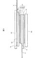
図1は、本発明の実施例1のタッチパネル付き表示装置300を示す概略断面図である。図1に示すように、本実施例の表示装置300は、液晶表示パネル600と、液晶液示パネル600の観察者側の面上に配置された静電容量方式のタッチパネル400と、液晶表示パネル600の観察者側とは反対側の面下に配置されたバックライト700とを備えている。液晶表示パネル600としては、例えばIPS方式、TN方式、VA方式等の液晶表示パネルが用いられている。
液晶表示パネル600は、対向して配置された2枚の基板620と630とが貼り合わされて形成されており、2枚の基板の外側には偏光板(601,602)が設けられている。また、液晶表示パネル600とタッチパネル400とは樹脂・粘着フィルム等からなる第1の接着材501により接合されている。さらに、タッチパネル400の外側にはアクリル樹脂からなる前面保護板(フロントパネル、前面パネルとも呼ぶ)120が樹脂・粘着フィルム等からなる第2の接着材502により貼り合わされている。なお、表示パネルとしては、タッチパネルを用いることができるものであれば良く、液晶表示パネルに限らず、有機発光ダイオード素子や表面伝導型電子放出素子を用いることも可能である。
Hereinafter, embodiments of the present invention will be described in detail with reference to the drawings.
In all the drawings for explaining the embodiments, parts having the same functions are given the same reference numerals, and repeated explanation thereof is omitted. Also, the following examples are not intended to limit the interpretation of the scope of the claims of the present invention.
[Example 1]
FIG. 1 is a schematic cross-sectional view illustrating a
The liquid
タッチパネル400の液晶表示パネル側には、透明導電層603が設けられている。この透明導電層603は液晶表示パネル600で発生する信号をシールドする目的で形成されている。
液晶表示パネル600には、多数の電極が設けられており、様々なタイミングで電極上に電圧が信号として印加されている。これらの液晶表示パネル600での電圧の変化は静電容量方式のタッチパネル400に設けられた電極に対してはノイズとなる。
そのため、タッチパネル400を液晶表示パネル600から電気的にシールドする必要があり透明導電層603がシールド電極として設けられている。シールド電極として機能するように、透明導電層603には定電圧がフレキシブルプリント基板70の所定の端子等から供給されており、例えば接地電位とされている。
なお、透明導電層603はノイズの影響を防止するために設けられるものであり、ノイズの影響が無い場合には、この透明導電層603を設ける必要はない。
A transparent
The liquid
Therefore, it is necessary to electrically shield the
Note that the transparent
液晶表示装置は、液晶表示パネル600と、液晶駆動回路(半導体チップ)50と、フレキシブルプリント基板72と、バックライト700から構成される。
液晶表示パネル600の基板620の一辺には、液晶駆動回路50が設けられており、この液晶駆動回路50により液晶表示パネル600に各種信号が供給される。液晶駆動回路50には外部からの信号を供給するためにフレキシブルプリント基板72が電気的に接続されている。
液晶表示パネル600は、薄膜トランジスタ、画素電極、対向電極(コモン電極)等が形成される基板620(以下、TFT基板とも呼ぶ)と、カラーフィルタ等が形成される基板630(以下、フィルタ基板とも呼ぶ)とを、所定の間隙を隔てて重ね合わせ、該両基板間の周縁部近傍に枠状に設けたシール材(図示せず)により、両基板を貼り合わせると共に、シール材の内側に液晶組成物を封入、封止し、さらに、両基板の外側に偏光板601、602を貼り付け、TFT基板620にフレキシブルプリント基板72を接続して構成される。図1では、液晶表示パネル600は、基板620が、液晶駆動回路(半導体チップ)50を搭載する領域が他方の基板630より突出しており1枚板の形状となっている。
なお、本発明は、対向電極がTFT基板620に設けられる所謂横電界方式の液晶表示パネルにも、対向電極がフィルタ基板630に設けられる所謂縦電界方式の液晶表示パネルにも同様に適用される。
The liquid crystal display device includes a liquid
A liquid
The liquid
The present invention is similarly applied to a so-called vertical electric field type liquid crystal display panel in which the counter electrode is provided on the
図2は、本発明の前提となる静電容量方式のタッチパネルの電極パターンを示す平面図である。
本発明の前提となる静電容量方式のタッチパネル20は、基板11の観察者側の面上において、第2の方向(例えばY方向)に延在し、第2の方向と交差する第1の方向(例えばX方向)に所定の配列ピッチで並設される複数のY電極と、この複数のX電極と交差して第1の方向に延在し、第2の方向に所定の配列ピッチで並設される複数のX電極とを有する。基板11としては、例えばガラス等の透明な絶縁性基板が用いられている。
複数のX電極の各々は、第1部分1aと、この第1部分1aの幅よりも広い幅の第2部分1bとが、第1の方向に交互に複数配置された電極パターンで形成されている。
複数のY電極の各々は、第1部分2aと、この第1部分2aの幅よりも広い幅の第2部分2bとが、第2の方向に交互に複数配置された電極パターンで形成されている。
複数のY電極2及びX電極1が配置された領域が入力領域であり、この入力領域の周囲には、図2に示すように、複数のY電極の各々と、複数のX電極の各々と電気的に接続される複数の配線MLが配置されている。
FIG. 2 is a plan view showing an electrode pattern of a capacitive touch panel which is a premise of the present invention.
The
Each of the plurality of X electrodes is formed by an electrode pattern in which a
Each of the plurality of Y electrodes is formed by an electrode pattern in which a
An area where the plurality of
図3、図4は、本発明の前提となる静電容量方式のタッチパネルの一例の断面構造を示す断面図であり、図3は、図2のA−A’線に沿った断面構造を示す断面図、図4は、図2のB−B’線に沿った断面構造を示す断面図である。
図3、図4に示す静電容量方式のタッチパネルでは、複数のY電極は、基板11の観察者側の面上に配置される。複数のX電極の第2部分2bは、基板11の観察者側の面上に、
Y電極とは分離して形成されている。
複数のX電極の第1部分1aは、基板11の観察者側の面上に形成された絶縁膜12上に配置される。なお、複数のX電極の第1部分1aは、その上層に形成された保護膜13で覆われている。
Y電極の第1部分2aは、X電極の第1部分1aと平面的に見て交差している。
X電極の第1部分1aは、Y電極の第1部分2aと絶縁膜12を介して交差している。また、X電極の第1部分1aは、この第1部分1aを挟んで隣り合う2つの第2部分1bに、X電極の第1部分1aと、X電極の第2部分1bとの間の層間絶縁膜である絶縁膜12に形成されたコンタクトホール12aを介してそれぞれ電気的に接続されている。
平面的に見たとき、Y電極の第2部分2bは、隣り合う2つのX電極の第1部分1aの間に配置され、X電極の第2部分1bは、隣り合う2つのY電極の第1部分2aの間に配置されている。
複数のX電極及び複数のY電極は、高い透過性を有する材料、例えばITO(Indium Tin Oxide)等の透明性導電材料で形成される。また、配線MLは、例えばITO(Indium Tin Oxide)等の透明性導電材料で形成される下層の透明導電層と、例えば、銀合金材料等から成る上層の金属層とで構成される。
3 and 4 are cross-sectional views showing a cross-sectional structure of an example of a capacitive touch panel as a premise of the present invention, and FIG. 3 shows a cross-sectional structure taken along the line AA ′ of FIG. 4 is a cross-sectional view showing a cross-sectional structure along the line BB ′ in FIG.
In the capacitive touch panel shown in FIGS. 3 and 4, the plurality of Y electrodes are arranged on the surface of the
It is formed separately from the Y electrode.
The
The
The
When viewed in plan, the
The plurality of X electrodes and the plurality of Y electrodes are formed of a highly transmissive material, for example, a transparent conductive material such as ITO (Indium Tin Oxide). The wiring ML is composed of a lower transparent conductive layer made of a transparent conductive material such as ITO (Indium Tin Oxide), and an upper metal layer made of, for example, a silver alloy material.
図5、図6は、本発明の前提となる静電容量方式のタッチパネルの他の断面構造を示す断面図であり、図5は、図2のA−A’線に沿った断面構造を示す断面図、図6は、図2のB−B’線に沿った断面構造を示す断面図である。
図5、図6に示す静電容量方式のタッチパネルでは、複数のX電極の第1部分1aが、基板11の観察者側の面上に形成され、複数のX電極の第2部分1bと、複数のY電極の第1部分2a及び第2部分2bは、絶縁膜12上に形成される。なお、複数のX電極の第2部分1bと、複数のY電極の第1部分2a及び第2部分2bは、その上層に形成された保護膜13で覆われている。
X電極の第1部分1aは、Y電極の第1部分2aと平面的に交差し、この第1部分1aを挟んで隣り合う2つの第2部分1bに、Y電極の第1部分2aと、X電極の第1部分1aとの間の層間絶縁膜である絶縁膜12に形成されたコンタクトホール12aを介してそれぞれ電気的に接続されている。
平面的に見たとき、Y電極の第2部分2bは、隣り合う2つのX電極の第1部分1aの間に配置され、X電極1の第2部分1bは、隣り合う2つのY電極の第1部分2aの間に配置されている。
複数のX電極及び複数のY電極は、高い透過性を有する材料、例えばITO(Indium Tin Oxide)等の透明性導電材料で形成される。また、配線MLは、例えばITO(Indium Tin Oxide)等の透明性導電材料で形成される下層の透明導電層と、例えば、銀合金材料等から成る上層の金属層とで構成される。
5 and 6 are cross-sectional views showing another cross-sectional structure of the capacitive touch panel which is a premise of the present invention, and FIG. 5 shows a cross-sectional structure taken along the line AA ′ of FIG. 6 is a cross-sectional view showing a cross-sectional structure along the line BB ′ in FIG.
In the capacitive touch panel shown in FIGS. 5 and 6, the
The
When viewed in a plan view, the
The plurality of X electrodes and the plurality of Y electrodes are formed of a highly transmissive material, for example, a transparent conductive material such as ITO (Indium Tin Oxide). Further, the wiring ML is composed of a lower transparent conductive layer made of a transparent conductive material such as ITO (Indium Tin Oxide), and an upper metal layer made of, for example, a silver alloy material.
[本発明の特徴]
図1に示すように、本実施例では、タッチパネル400の基板(図2〜図6の基板11)の一辺に接続されるフレキシブルプリント基板70と、液晶表示パネル600の基板620の一辺に接続されるフレキシブルプリント基板72とが左右両側から取り出されている。そこで、本発明では、タッチパネル400の基板の観察者側の表面で、液晶表示パネル600の基板620に搭載される液晶駆動回路50上の領域に、シールド電極30を形成したことを特徴とする。
このシールド電極30には、定電圧(例えば、接地電位)がフレキシブルプリント基板70の所定の端子等から供給されている。
前述したように、例えば、携帯電話機用の液晶表示装置の場合、液晶駆動回路50から放射される不要輻射により、携帯電話実機に有するアンテナの無線感度が低下してしまうことが判っているが、本実施例では、タッチパネル400の基板の観察者側の表面で、液晶表示パネル600の基板620に搭載される液晶駆動回路50上の領域に、シールド電極30を形成し、液晶駆動回路50の上部を静電遮蔽することにより、不要輻射を低減させるようにしたものである。これにより、例えば、携帯電話機用の液晶表示装置の場合、液晶駆動回路50から放射される不要輻射により、携帯電話実機に有するアンテナの無線感度が低下するのを抑制することができる。
[Features of the present invention]
As shown in FIG. 1, in this embodiment, the flexible printed
A constant voltage (for example, ground potential) is supplied to the
As described above, for example, in the case of a liquid crystal display device for a mobile phone, it is known that the radio sensitivity of the antenna included in the actual mobile phone is reduced due to unnecessary radiation radiated from the liquid
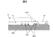
図7は、本実施例のシールド電極30の部分を説明するための図であり、図8は、本実施例のシールド電極30の部分の断面構造を示す要部断面図である。
本実施例では、図7に示すように、タッチ領域の外側に形成された配線MLの外側に設けたシールド電極用の配線31Mを介して、シールド電極30に、フレキシブルプリント基板70の所定の端子から定電圧(例えば、接地電位)が供給される。ここで、フレキシブルプリント基板70の所定の端子から、シールド電極30の両側に定電圧(例えば、接地電位)を供給している。そのため、シールド電極30と、シールド電極用の配線31Mとで、ループを形成し、ループアンテナとして機能する場合には、フレキシブルプリント基板70の所定の端子から、シールド電極30の片側にのみ、定電圧(例えば、接地電位)を供給するようにしてもよい。
また、図8に示すように、シールド電極30は、下層透明導電膜(ITO1)と、下層透明導電膜(ITO1)上に形成されたメタル層(MET)と、絶縁膜12に形成された凹部から露出する下層透明導電膜(ITO1)上に形成される上層側透明導電膜(ITO2)とで構成される。なお、シールド電極30は、下層透明導電膜(ITO1)と、メタル層(MET)と、上層透明導電膜(ITO2)の積層構造が望ましいが、場合によっては、シールド電極30は、下層透明導電膜(ITO1)と、メタル層(MET)と、上層透明導電膜(ITO2)の中の少なくとも1層であってもよい。
また、図8では、タッチ領域の外側に形成された配線MLも、下層透明導電膜(ITO1)と、下層透明導電膜(ITO1)上に形成されたメタル層(MET)とで構成される。
ここで、図3、図4に示すタイプのタッチパネルであれば、下層透明導電膜(ITO1)は、Y電極の第1部分(2a)および第2部分(2b)と、X電極の第2部分(1b)を構成する透明導電膜、上層透明導電膜(ITO2)は、X電極の第1部分(1a)を構成する透明導電膜と同一工程で作製される。
また、図5、図6に示すタイプのタッチパネルであれば、下層透明導電膜(ITO1)は、X電極の第1部分(1a)を構成する透明導電膜、上層透明導電膜(ITO2)は、Y電極の第1部分(2a)および第2部分(2b)と、X電極の第2部分(1b)を構成する透明導電膜と同一工程で作製される。
FIG. 7 is a diagram for explaining a portion of the
In the present embodiment, as shown in FIG. 7, predetermined terminals of the flexible printed
As shown in FIG. 8, the
In FIG. 8, the wiring ML formed outside the touch region is also composed of a lower transparent conductive film (ITO1) and a metal layer (MET) formed on the lower transparent conductive film (ITO1).
If the touch panel of the type shown in FIGS. 3 and 4 is used, the lower transparent conductive film (ITO1) includes the first part (2a) and the second part (2b) of the Y electrode and the second part of the X electrode. The transparent conductive film constituting the (1b) and the upper transparent conductive film (ITO2) are produced in the same process as the transparent conductive film constituting the first part (1a) of the X electrode.
If the touch panel is of the type shown in FIGS. 5 and 6, the lower transparent conductive film (ITO1) is the transparent conductive film constituting the first portion (1a) of the X electrode, and the upper transparent conductive film (ITO2) is The transparent conductive film which comprises the 1st part (2a) and 2nd part (2b) of a Y electrode, and the 2nd part (1b) of a X electrode is produced at the same process.
[実施例2]
図9は、本発明の実施例2のシールド電極30の部分を説明するための図であり、図10は、本発明の実施例2のフレキシブルプリント基板70の部分を説明するための図である。
本実施例のタッチパネル400は、図3、図4に示すタッチパネルで構成される。本実施例では、少なくとも1本のシールド電極用透明配線31を、絶縁膜12上に形成し、シールド電極30に、少なくとも1本のシールド電極用透明配線31を介して、フレキシブルプリント基板70の所定の端子から定電圧(例えば、接地電位)を供給するようにしたものである。
この場合、図10のAに示すように、少なくとも1本のシールド電極用透明配線31を直接フレキシブルプリント基板70の所定の端子に接続してもよく、あるいは、少なくとも1本のシールド電極用透明配線31を、フレキシブルプリント基板70付近まで延長し、基板11に形成された透明導電膜(ITO3)に接続し、透明導電膜(ITO3)でフレキシブルプリント基板70の所定の端子に接続するようにしてもよい。ここで、少なくとも1本のシールド電極用透明配線31は、図8に示す上層透明導電膜(ITO2)と同一工程で作製され、透明導電膜(ITO3)は、図8に示す下層透明導電膜(ITO1)と同一工程で作製される。
なお、本実施例では、図9に示すように、シールド電極用の配線31Mを介して、フレキシブルプリント基板70の所定の端子から、シールド電極30に定電圧(例えば、接地電位)を供給しているが、少なくとも1本のシールド電極用透明配線31のみで、フレキシブルプリント基板70の所定の端子から定電圧(例えば、接地電位)を供給するようにしてもよい。
[Example 2]
FIG. 9 is a diagram for explaining a portion of the
The
In this case, as shown in FIG. 10A, at least one shield electrode
In this embodiment, as shown in FIG. 9, a constant voltage (for example, ground potential) is supplied to the
[実施例3]
図11は、本発明の実施例3のシールド電極30の部分を説明するための図であり、図12は、本発明の実施例3のフレキシブルプリント基板70の部分を説明するための図である。
本実施例のタッチパネル400は、図5、図6に示すタッチパネルで構成される。本実施例は、少なくとも1本のシールド電極用透明配線31を、基板11上に形成し、シールド電極30に、少なくとも1本のシールド電極用透明配線31を介して、フレキシブルプリント基板70の所定の端子から定電圧(例えば、接地電位)を供給するようにしたものである。
この場合、図12に示すように、少なくとも1本のシールド電極用透明配線31は基板11に形成されるので、少なくとも1本のシールド電極用透明配線31を直接フレキシブルプリント基板70の所定の端子に接続することができる。
前述の実施例2では、少なくとも1本のシールド電極用透明配線31は、X電極の第2部分(1b)上に配置されるため、タッチパネル400の電極感度が低下する恐れがあるが、本実施例では、少なくとも1本のシールド電極用透明配線31は、X電極の第2部分(1b)の下に配置されるため、タッチパネル400の電極感度が低下する恐れがない。ここで、少なくとも1本のシールド電極用透明配線31は、図8に示す下層透明導電膜(ITO1)と同一工程で作製される。
なお、本実施例では、図11に示すように、シールド電極用の配線31Mを介して、フレキシブルプリント基板70の所定の端子から、シールド電極30に定電圧(例えば、接地電位)を供給しているが、少なくとも1本のシールド電極用透明配線31のみで、フレキシブルプリント基板70の所定の端子から定電圧(例えば、接地電位)を供給するようにしてもよい。
[Example 3]
FIG. 11 is a view for explaining a portion of the
The
In this case, as shown in FIG. 12, since at least one shield electrode
In Example 2 described above, at least one shield electrode
In this embodiment, as shown in FIG. 11, a constant voltage (for example, ground potential) is supplied to the
[実施例4]
図13は、本発明の実施例4のシールド電極30の部分を説明するための図である。
本実施例のタッチパネル400は、図3、図4に示すタッチパネルで構成される。本実施例は、少なくとも1本のシールド電極用透明配線31を、基板11上で、Y電極の間に形成するようにしたものである。本実施例でも、少なくとも1本のシールド電極用透明配線31は基板11に形成されるので、少なくとも1本のシールド電極用透明配線31を直接フレキシブルプリント基板70に接続することができる。
ここで、少なくとも1本のシールド電極用透明配線31は、図8に示す下層透明導電膜(ITO1)と同一工程で作製される。
なお、本実施例では、図13に示すように、シールド電極用の配線31Mを介して、フレキシブルプリント基板70の所定の端子から、シールド電極30に定電圧(例えば、接地電位)を供給しているが、少なくとも1本のシールド電極用透明配線31のみで、フレキシブルプリント基板70の所定の端子から定電圧(例えば、接地電位)を供給するようにしてもよい。
[Example 4]
FIG. 13 is a diagram for explaining a portion of the
The
Here, at least one shield electrode
In this embodiment, as shown in FIG. 13, a constant voltage (for example, ground potential) is supplied to the
[実施例5]
図14は、本発明の実施例5のシールド電極30の給電方法を説明するための図である。
本実施例では、タッチパネル400のシールド電極30に、フレキシブルプリント基板70の所定の端子から定電圧(例えば、接地電位)を供給する代わりに、表示パネル側から定電圧(例えば、接地電位)を供給するようにしたものである。
IPS方式の液晶表示パネルの場合、上偏光板601上、あるいは、上偏光板601と基板630との間に裏面導電膜を形成し、この裏面導電膜に、導電部(T−GND)を介してフレキシブルプリント基板72から定電圧(例えば、接地電位)を供給している。
そこで、本実施例では、シールド電極30(図14では、透明導電層603も)上に導電性テープ35を貼り付け、この導電性テープ35を、液晶表示パネルの導電部(T−GND)に接続し、シールド電極30に、表示パネルから定電圧(例えば、接地電位)を供給するようにしたものである。
なお、本実施例でも、シールド電極用の配線31Mを介して、フレキシブルプリント基板70の所定の端子から、シールド電極30に定電圧(例えば、接地電位)を供給しているが、表示パネルからのみ、定電圧(例えば、接地電位)を供給するようにしてもよい。
[Example 5]
FIG. 14 is a diagram for explaining a power feeding method for the
In this embodiment, instead of supplying a constant voltage (for example, ground potential) from a predetermined terminal of the flexible printed
In the case of an IPS liquid crystal display panel, a back conductive film is formed on the upper
Therefore, in this embodiment, the
Also in this embodiment, a constant voltage (for example, ground potential) is supplied to the
[実施例6]
図15は、本発明の実施例6のシールド電極30の給電方法を説明するための図である。なお、図15において、MFLは、バックライト700の一部を構成する下フレーム、61は、バックライト700の一部を構成する導光板、62は、バックライト700の一部を構成する反射シート、63は、バックライト700の一部を構成する光学シート群である。
本実施例でも、タッチパネル400のシールド電極30に、フレキシブルプリント基板70の所定の端子から定電圧(例えば、接地電位)を供給する代わりに、表示パネル側から定電圧(例えば、接地電位)を供給するようにしたものである。
液晶表示パネルのバックライト700の中には、下フレーム(MFL)を有するものがある。そこで、本実施例では、シールド電極30(図15では、透明導電層603も)上に導電性テープ35を貼り付け、この導電性テープ35を、液晶表示パネルのバックライト700の下フレーム(MFL)に接続し、シールド電極30に、表示パネルから定電圧(例えば、接地電位)を供給するようにしたものである。
また、本実施例において、シールド電極30(図15では、透明導電層603も)上に貼り付けた導電性テープ35を、液晶表示パネルのフレキシブルプリント基板72上の定電圧(例えば、接地電位)を供給されている端子に接続し、シールド電極30に、表示パネルから定電圧(例えば、接地電位)を供給するようにしてもよい。
なお、本実施例でも、シールド電極用の配線31Mを介して、フレキシブルプリント基板70の所定の端子から、シールド電極30に定電圧(例えば、接地電位)を供給しているが、表示パネルからのみ、定電圧(例えば、接地電位)を供給するようにしてもよい。
[Example 6]
FIG. 15 is a diagram for explaining a method of feeding the
Also in this embodiment, instead of supplying a constant voltage (for example, ground potential) from a predetermined terminal of the flexible printed
Some
In this embodiment, the
Also in this embodiment, a constant voltage (for example, ground potential) is supplied to the
以上説明したように、本実施例によれば、液晶駆動回路50から放射される不要輻射を抑制することができるので、例えば、携帯電話機のアンテナの無線感度低下を抑制すること可能となる。
また、液晶駆動回路50の上部にタッチパネル400の基板(例えば、ガラス基板)11を位置させ、該当部のクリアランスを狭めることにより、液晶表示パネルの基板620の基板割れに対する強度を向上させることができる。
さらに、前述の各実施例のシールド電極30およびその給電用の配線は、静電容量方式のタッチパネル400の各電極の形成に必要な材料で賄えるため、コストを上昇させることなく、液晶駆動回路50から放射される不要輻射を低減することができる。
以上、本発明者によってなされた発明を、前記実施例に基づき具体的に説明したが、本発明は、前記実施例に限定されるものではなく、その要旨を逸脱しない範囲において種々変更可能であることは勿論である。
As described above, according to the present embodiment, unnecessary radiation radiated from the liquid
Further, by positioning the substrate (for example, glass substrate) 11 of the
Further, since the
As mentioned above, the invention made by the present inventor has been specifically described based on the above embodiments. However, the present invention is not limited to the above embodiments, and various modifications can be made without departing from the scope of the invention. Of course.
1a,2a 第1部分
1b,2b 第2部分
11 基板
12 絶縁膜
12a コンタクトホール
13 保護膜
20 タッチパネル
30 シールド電極
31 シールド電極用透明配線
31M シールド電極用の配線
35 導電性テープ
50 液晶駆動回路
61 導光板
62 反射シート
63 光学シート群
70,72 フレキシブルプリント基板
120 フロントパネル
300 表示装置
400 タッチパネル
501 第1の接着材
502 第2の接着材
600 液晶表示パネル
601,602 偏光板
603 透明導電層
620,630 基板
700 バックライト
ML 配線
MET メタル層
MFL 下フレーム
ITO1 下層透明導電膜
ITO2 上層透明導電膜
ITO3 透明導電膜
LED 発光ダイオード
DESCRIPTION OF
Claims (19)
前記表示パネル上に配置されたタッチパネルとを備える表示装置であって、
前記表示パネルは、半導体チップを有し、
前記タッチパネルは、タッチパネル基板と、
前記タッチパネル基板上に形成され、且つ平面的に見て前記半導体チップと重畳する位置に配置された第1の電極を有し、
前記第1の電極には所定の電圧が供給されており、
前記タッチパネルは、タッチ位置を検出可能なタッチ領域と、前記タッチ領域に形成されたタッチ位置を検出する第2の電極とを有し、
前記第1の電極は、前記タッチ領域の外側に配置されていることを特徴とする表示装置。 A display panel;
A display device comprising a touch panel disposed on the display panel,
The display panel has a semiconductor chip,
The touch panel includes a touch panel substrate,
A first electrode formed on the touch panel substrate and disposed at a position overlapping the semiconductor chip in plan view;
A predetermined voltage is supplied to the first electrode,
The touch panel includes a touch area in which a touch position can be detected, and a second electrode that detects the touch position formed in the touch area,
The first electrode, the display device you characterized in that it is disposed outside of the touch region.
前記タッチパネル基板の前記第1の電極が形成される側と反対側には、タッチパネル用のフレキシブル配線基板が接続され、
前記タッチパネル基板上で、前記第1の電極が形成される辺と直交する2辺の少なくとも1辺の周辺部に形成される第1の電極用配線とを有し、
前記第1の電極には、前記第1の電極用配線を介して、前記タッチパネル用のフレキシブル配線基板から前記所定の電圧が供給されていることを特徴とする請求項1に記載の表示装置。 The display panel has a flexible wiring substrate for a display panel on a side on which the semiconductor chip is mounted,
A flexible wiring board for a touch panel is connected to the side opposite to the side on which the first electrode is formed of the touch panel substrate,
A first electrode wiring formed on a periphery of at least one of two sides orthogonal to a side on which the first electrode is formed on the touch panel substrate;
The display device according to claim 1 , wherein the predetermined voltage is supplied to the first electrode from the flexible wiring substrate for the touch panel through the first electrode wiring.
前記タッチパネル基板上の、前記第1の電極が形成される辺と直交する2辺の周辺部には、前記X電極と前記Y電極に接続される第2の電極用配線が形成され、
前記第1の電極用配線は、前記第2の電極用配線の外側に形成されていることを特徴とする請求項2に記載の表示装置。 The second electrode has an X electrode and a Y electrode,
A second electrode wiring connected to the X electrode and the Y electrode is formed on the periphery of the two sides orthogonal to the side on which the first electrode is formed on the touch panel substrate,
The display device according to claim 2 , wherein the first electrode wiring is formed outside the second electrode wiring.
前記タッチパネルは、前記X電極および前記Y電極上に形成された層間絶縁膜と、
前記層間絶縁膜上に形成された少なくとも1本の第1の電極用透明配線とを有し、
前記第1の電極には、前記少なくとも1本の第1の電極用透明配線を介して、前記タッチパネル用のフレキシブル配線基板から前記所定の電圧が供給されていることを特徴とする請求項2に記載の表示装置。 The second electrode has an X electrode and a Y electrode,
The touch panel includes an interlayer insulating film formed on the X electrode and the Y electrode,
And at least one first electrode transparent wiring formed on the interlayer insulating film,
Wherein the first electrode, the via at least one first transparent wiring electrode, to claim 2, wherein the predetermined voltage from the flexible wiring board for the touch panel is characterized in that it is supplied The display device described.
前記タッチパネルは、前記X電極あるいは前記Y電極の隙間に形成された少なくとも1本の第1の電極用透明配線を有し、
前記第1の電極には、前記少なくとも1本の第1の電極用透明配線を介して、前記タッチパネル用のフレキシブル配線基板から前記所定の電圧が供給されていることを特徴とする請求項2に記載の表示装置。 The second electrode has an X electrode and a Y electrode,
The touch panel has at least one first electrode transparent wiring formed in a gap between the X electrode or the Y electrode,
Wherein the first electrode, the via at least one first transparent wiring electrode, to claim 2, wherein the predetermined voltage from the flexible wiring board for the touch panel is characterized in that it is supplied The display device described.
前記第1の電極には、前記導電部を介して、前記所定の電圧が供給されていることを特徴とする請求項1に記載の表示装置。 The display panel has a conductive part to which the predetermined voltage is supplied,
Wherein the first electrode, via the conductive portion, a display device according to claim 1, wherein the predetermined voltage, characterized in that it is supplied.
前記表示パネルの前記タッチパネルと対向する側の基板には、裏面透明導電膜が形成され、
前記導電部は、前記裏面透明導電膜に電気的に接続されることを特徴とする請求項6に記載の表示装置。 The display panel is an IPS liquid crystal display panel;
A back transparent conductive film is formed on the substrate facing the touch panel of the display panel,
The display device according to claim 6 , wherein the conductive portion is electrically connected to the back transparent conductive film.
前記第1の電極には、導電部材を介して、前記表示パネル用のフレキシブル配線基板から前記所定の電圧が供給されていることを特徴とする請求項1に記載の表示装置。 The display panel has a flexible wiring substrate for a display panel on a side on which the semiconductor chip is mounted,
The display device according to claim 1, wherein the predetermined voltage is supplied to the first electrode from a flexible wiring substrate for the display panel via a conductive member.
前記第1の電極には、導電部材を介して、前記表示パネルの前記金属フレームから前記所定の電圧が供給されていることを特徴とする請求項1に記載の表示装置。 The display panel has a metal frame to which the predetermined voltage is supplied,
The display device according to claim 1, wherein the predetermined voltage is supplied to the first electrode from the metal frame of the display panel via a conductive member.
前記表示パネル上に配置され、X電極およびY電極を有するタッチパネルとを備える表示装置であって、
前記表示パネルは、半導体チップを有し、
前記タッチパネルは、前記X電極および前記Y電極が形成されるタッチパネル基板と、
前記X電極および前記Y電極上に形成された層間絶縁膜と、
前記層間絶縁膜上に形成された少なくとも1本のシールド電極用透明配線と、
前記タッチパネル基板上で、前記表示パネルの前記半導体チップ上の領域に形成されるシールド電極とを有し、
前記タッチパネル基板の前記シールド電極が形成される側と反対側には、タッチパネル用のフレキシブル配線基板が接続され、
前記シールド電極には、前記少なくとも1本のシールド電極用透明配線を介して、前記タッチパネル用のフレキシブル配線基板から所定の電圧が供給されていることを特徴とする表示装置。 A display panel;
A display device that is disposed on the display panel and includes a touch panel having an X electrode and a Y electrode,
The display panel has a semiconductor chip,
The touch panel includes a touch panel substrate on which the X electrode and the Y electrode are formed,
An interlayer insulating film formed on the X electrode and the Y electrode;
At least one shield electrode transparent wiring formed on the interlayer insulating film;
On the touch panel substrate, having a shield electrode formed in a region on the semiconductor chip of the display panel,
On the opposite side of the touch panel substrate where the shield electrode is formed, a flexible wiring substrate for the touch panel is connected,
A display device, wherein a predetermined voltage is supplied to the shield electrode from the flexible wiring substrate for the touch panel through the at least one transparent electrode for the shield electrode.
前記表示パネル上に配置され、X電極およびY電極を有するタッチパネルとを備える表示装置であって、
前記表示パネルは、半導体チップを有し、
前記タッチパネルは、タッチパネル基板と、
前記タッチパネル基板上に形成された少なくとも1本のシールド電極用透明配線と、
前記タッチパネル基板上で、前記表示パネルの前記半導体チップ上の領域に形成されるシールド電極とを有し、
前記タッチパネル基板の前記シールド電極が形成される側と反対側には、タッチパネル用のフレキシブル配線基板が接続され、
前記シールド電極には、前記少なくとも1本のシールド電極用透明配線を介して、前記タッチパネル用のフレキシブル配線基板から所定の電圧が供給されていることを特徴とする表示装置。 A display panel;
A display device that is disposed on the display panel and includes a touch panel having an X electrode and a Y electrode,
The display panel has a semiconductor chip,
The touch panel includes a touch panel substrate,
At least one shield electrode transparent wiring formed on the touch panel substrate;
On the touch panel substrate, having a shield electrode formed in a region on the semiconductor chip of the display panel,
On the opposite side of the touch panel substrate where the shield electrode is formed, a flexible wiring substrate for the touch panel is connected,
A display device, wherein a predetermined voltage is supplied to the shield electrode from the flexible wiring substrate for the touch panel through the at least one transparent electrode for the shield electrode.
前記表示パネル上に配置され、X電極およびY電極を有するタッチパネルとを備える表示装置であって、
前記表示パネルは、半導体チップを有し、
前記タッチパネルは、前記X電極および前記Y電極が形成されるタッチパネル基板と、
前記X電極あるいはY電極の隙間に形成された少なくとも1本のシールド電極用透明配線と、
前記タッチパネル基板上で、前記表示パネルの前記半導体チップ上の領域に形成されるシールド電極とを有し、
前記タッチパネル基板の前記シールド電極が形成される側と反対側には、タッチパネル用のフレキシブル配線基板が接続され、
前記シールド電極には、前記少なくとも1本のシールド電極用透明配線を介して、前記タッチパネル用のフレキシブル配線基板から所定の電圧が供給されていることを特徴とする表示装置。 A display panel;
A display device that is disposed on the display panel and includes a touch panel having an X electrode and a Y electrode,
The display panel has a semiconductor chip,
The touch panel includes a touch panel substrate on which the X electrode and the Y electrode are formed,
At least one shield electrode transparent wiring formed in a gap between the X electrode or the Y electrode;
On the touch panel substrate, having a shield electrode formed in a region on the semiconductor chip of the display panel,
On the opposite side of the touch panel substrate where the shield electrode is formed, a flexible wiring substrate for the touch panel is connected,
A display device, wherein a predetermined voltage is supplied to the shield electrode from the flexible wiring substrate for the touch panel through the at least one transparent electrode for the shield electrode.
前記表示パネル上に配置され、X電極およびY電極を有するタッチパネルとを備える表示装置であって、
前記表示パネルは、半導体チップと、
所定の電圧が供給されている導電部とを有し、
前記タッチパネルは、タッチパネル基板と、
前記タッチパネル基板上で、前記表示パネルの前記半導体チップ上の領域に形成されるシールド電極とを有し、
前記タッチパネル基板の前記シールド電極が形成される側と反対側には、タッチパネル用のフレキシブル配線基板が接続され、
前記シールド電極には、導電部材を介して、前記表示パネルの前記導電部から前記所定の電圧が供給されていることを特徴とする表示装置。 A display panel;
A display device that is disposed on the display panel and includes a touch panel having an X electrode and a Y electrode,
The display panel includes a semiconductor chip,
A conductive portion to which a predetermined voltage is supplied,
The touch panel includes a touch panel substrate,
On the touch panel substrate, having a shield electrode formed in a region on the semiconductor chip of the display panel,
On the opposite side of the touch panel substrate where the shield electrode is formed, a flexible wiring substrate for the touch panel is connected,
The display device, wherein the predetermined voltage is supplied to the shield electrode from the conductive portion of the display panel via a conductive member.
前記表示パネルの前記タッチパネルと対向する側の基板には、裏面透明導電膜が形成され、
前記導電部は、前記裏面透明導電膜に電気的に接続されることを特徴とする請求項14に記載の表示装置。 The display panel is an IPS liquid crystal display panel;
A back transparent conductive film is formed on the substrate facing the touch panel of the display panel,
The display device according to claim 14 , wherein the conductive portion is electrically connected to the back transparent conductive film.
前記表示パネル上に配置され、X電極およびY電極を有するタッチパネルとを備える表示装置であって、
前記表示パネルは、半導体チップを有し、
前記表示パネルの前記半導体チップが搭載される側の辺には、表示パネル用のフレキシブル配線基板が接続され、
前記タッチパネルは、タッチパネル基板と、
前記タッチパネル基板上で、前記表示パネルの前記半導体チップ上の領域に形成されるシールド電極とを有し、
前記タッチパネル基板の前記シールド電極が形成される側と反対側には、タッチパネル用のフレキシブル配線基板が接続され、
前記シールド電極には、導電部材を介して、前記表示パネル用のフレキシブル配線基板から所定の電圧が供給されていることを特徴とする表示装置。 A display panel;
A display device that is disposed on the display panel and includes a touch panel having an X electrode and a Y electrode,
The display panel has a semiconductor chip,
A flexible wiring board for the display panel is connected to the side of the display panel where the semiconductor chip is mounted,
The touch panel includes a touch panel substrate,
On the touch panel substrate, having a shield electrode formed in a region on the semiconductor chip of the display panel,
On the opposite side of the touch panel substrate where the shield electrode is formed, a flexible wiring substrate for the touch panel is connected,
The display device, wherein a predetermined voltage is supplied to the shield electrode from the flexible wiring substrate for the display panel via a conductive member.
前記表示パネル上に配置され、X電極およびY電極を有するタッチパネルとを備える表示装置であって、
前記表示パネルは、半導体チップと、
所定の電圧が供給される金属フレームとを有し、
前記タッチパネルは、タッチパネル基板と、
前記タッチパネル基板上で、前記表示パネルの前記半導体チップ上の領域に形成されるシールド電極とを有し、
前記タッチパネル基板の前記シールド電極が形成される側と反対側には、タッチパネル用のフレキシブル配線基板が接続され、
前記シールド電極には、導電部材を介して、前記表示パネルの前記金属フレームから前記所定の電圧が供給されていることを特徴とする表示装置。 A display panel;
A display device that is disposed on the display panel and includes a touch panel having an X electrode and a Y electrode,
The display panel includes a semiconductor chip,
A metal frame to which a predetermined voltage is supplied,
The touch panel includes a touch panel substrate,
On the touch panel substrate, having a shield electrode formed in a region on the semiconductor chip of the display panel,
On the opposite side of the touch panel substrate where the shield electrode is formed, a flexible wiring substrate for the touch panel is connected,
The display device, wherein the predetermined voltage is supplied to the shield electrode from the metal frame of the display panel via a conductive member.
前記表示パネル上に配置された第1の電極と第2の電極とを備える表示装置であって、
前記第1の電極は、平面的に見て前記半導体チップと重畳する位置に配置され、
前記第2の電極は、タッチ位置を検出する電極であり、
前記第1の電極には所定の電位が供給されており、
前記第1の電極と前記第2の電極とは同層に形成され、
前記第2の電極は、タッチ位置を検出可能なタッチ領域に位置し、
前記第1の電極は、前記タッチ領域の外側に位置していることを特徴とする表示装置。 A display panel having a semiconductor chip;
A display device comprising a first electrode and a second electrode disposed on the display panel,
The first electrode is disposed at a position overlapping with the semiconductor chip when seen in a plan view,
The second electrode is an electrode for detecting a touch position;
A predetermined potential is supplied to the first electrode,
The first electrode and the second electrode are formed in the same layer,
The second electrode is located in a touch area where a touch position can be detected,
The first electrode, the display device you characterized by being located outside of the touch region.
Priority Applications (1)
| Application Number | Priority Date | Filing Date | Title |
|---|---|---|---|
| JP2010059260A JP5453146B2 (en) | 2010-03-16 | 2010-03-16 | Display device |
Applications Claiming Priority (1)
| Application Number | Priority Date | Filing Date | Title |
|---|---|---|---|
| JP2010059260A JP5453146B2 (en) | 2010-03-16 | 2010-03-16 | Display device |
Related Child Applications (1)
| Application Number | Title | Priority Date | Filing Date |
|---|---|---|---|
| JP2014000096A Division JP5805797B2 (en) | 2014-01-06 | 2014-01-06 | Display device |
Publications (3)
| Publication Number | Publication Date |
|---|---|
| JP2011191639A JP2011191639A (en) | 2011-09-29 |
| JP2011191639A5 JP2011191639A5 (en) | 2013-03-14 |
| JP5453146B2 true JP5453146B2 (en) | 2014-03-26 |
Family
ID=44796598
Family Applications (1)
| Application Number | Title | Priority Date | Filing Date |
|---|---|---|---|
| JP2010059260A Active JP5453146B2 (en) | 2010-03-16 | 2010-03-16 | Display device |
Country Status (1)
| Country | Link |
|---|---|
| JP (1) | JP5453146B2 (en) |
Cited By (1)
| Publication number | Priority date | Publication date | Assignee | Title |
|---|---|---|---|---|
| CN104503121A (en) * | 2014-12-24 | 2015-04-08 | 深圳市华星光电技术有限公司 | Touch liquid crystal display panel and touch liquid crystal display device |
Families Citing this family (5)
| Publication number | Priority date | Publication date | Assignee | Title |
|---|---|---|---|---|
| KR20130115621A (en) | 2012-04-12 | 2013-10-22 | 삼성디스플레이 주식회사 | Display device and fabrication method of the same |
| KR101320525B1 (en) * | 2012-11-12 | 2013-10-23 | 일신전자 주식회사 | Touch panel and manufacturing method thereof |
| JP6315892B2 (en) * | 2013-05-15 | 2018-04-25 | 三菱電機株式会社 | LCD panel |
| JP6412810B2 (en) * | 2015-01-28 | 2018-10-24 | 株式会社ジャパンディスプレイ | Display module |
| CN111078050A (en) * | 2019-12-18 | 2020-04-28 | 京东方科技集团股份有限公司 | Touch display panel and display device |
Family Cites Families (3)
| Publication number | Priority date | Publication date | Assignee | Title |
|---|---|---|---|---|
| JP2009086184A (en) * | 2007-09-28 | 2009-04-23 | Casio Comput Co Ltd | Liquid crystal display device with touch panel |
| KR20090037547A (en) * | 2007-10-12 | 2009-04-16 | 삼성전자주식회사 | Display device |
| JP2009098834A (en) * | 2007-10-16 | 2009-05-07 | Epson Imaging Devices Corp | Capacitance type input device, display device with input function and electronic equipment |
-
2010
- 2010-03-16 JP JP2010059260A patent/JP5453146B2/en active Active
Cited By (2)
| Publication number | Priority date | Publication date | Assignee | Title |
|---|---|---|---|---|
| CN104503121A (en) * | 2014-12-24 | 2015-04-08 | 深圳市华星光电技术有限公司 | Touch liquid crystal display panel and touch liquid crystal display device |
| WO2016101292A1 (en) * | 2014-12-24 | 2016-06-30 | 深圳市华星光电技术有限公司 | Touch liquid crystal display panel and touch liquid crystal display device |
Also Published As
| Publication number | Publication date |
|---|---|
| JP2011191639A (en) | 2011-09-29 |
Similar Documents
| Publication | Publication Date | Title |
|---|---|---|
| US10635239B2 (en) | Electrostatic capacitance-type input device | |
| JP5805797B2 (en) | Display device | |
| US8698776B2 (en) | Electrostatic capacitance-type input device, method of manufacturing electrostatic capacitance-type input device, and electro-optical apparatus provided with input function | |
| TWI477851B (en) | Touch sensing display panel and touch sensing liquid crystal display panel | |
| US8780284B2 (en) | Capacitive input device and electro-optical apparatus with input function | |
| JP5033078B2 (en) | Display device | |
| JP5133204B2 (en) | Touch panel | |
| KR101682755B1 (en) | Electronic component, touch panel and liquid crystal display device using the same | |
| US9823502B2 (en) | Method and apparatus for color filter as touch pad | |
| WO2009125531A1 (en) | Touch panel and display equipped with the same | |
| TWI657362B (en) | Touch device | |
| JP5453146B2 (en) | Display device | |
| JP2012084025A (en) | Display device with touch panel | |
| JP5718889B2 (en) | Touch panel | |
| KR20200007110A (en) | Display device | |
| TW201504900A (en) | Touch display apparatus | |
| JP5981005B2 (en) | Display device | |
| KR20130116854A (en) | Touch window | |
| JP2011186623A (en) | Display device with touch panel | |
| KR101415585B1 (en) | Touch window and liquid crystal display comprised of the touch window | |
| JP2018205633A (en) | Display and method for manufacturing display |
Legal Events
| Date | Code | Title | Description |
|---|---|---|---|
| A521 | Request for written amendment filed |
Free format text: JAPANESE INTERMEDIATE CODE: A523 Effective date: 20130125 |
|
| A621 | Written request for application examination |
Free format text: JAPANESE INTERMEDIATE CODE: A621 Effective date: 20130125 |
|
| A977 | Report on retrieval |
Free format text: JAPANESE INTERMEDIATE CODE: A971007 Effective date: 20130731 |
|
| A131 | Notification of reasons for refusal |
Free format text: JAPANESE INTERMEDIATE CODE: A131 Effective date: 20130806 |
|
| A521 | Request for written amendment filed |
Free format text: JAPANESE INTERMEDIATE CODE: A523 Effective date: 20131004 |
|
| RD02 | Notification of acceptance of power of attorney |
Free format text: JAPANESE INTERMEDIATE CODE: A7422 Effective date: 20131023 |
|
| TRDD | Decision of grant or rejection written | ||
| A01 | Written decision to grant a patent or to grant a registration (utility model) |
Free format text: JAPANESE INTERMEDIATE CODE: A01 Effective date: 20131210 |
|
| A61 | First payment of annual fees (during grant procedure) |
Free format text: JAPANESE INTERMEDIATE CODE: A61 Effective date: 20140106 |
|
| R150 | Certificate of patent or registration of utility model |
Free format text: JAPANESE INTERMEDIATE CODE: R150 Ref document number: 5453146 Country of ref document: JP Free format text: JAPANESE INTERMEDIATE CODE: R150 |
|
| R250 | Receipt of annual fees |
Free format text: JAPANESE INTERMEDIATE CODE: R250 |
|
| R250 | Receipt of annual fees |
Free format text: JAPANESE INTERMEDIATE CODE: R250 |
|
| R250 | Receipt of annual fees |
Free format text: JAPANESE INTERMEDIATE CODE: R250 |
|
| R250 | Receipt of annual fees |
Free format text: JAPANESE INTERMEDIATE CODE: R250 |
|
| R250 | Receipt of annual fees |
Free format text: JAPANESE INTERMEDIATE CODE: R250 |
|
| R250 | Receipt of annual fees |
Free format text: JAPANESE INTERMEDIATE CODE: R250 |
|
| R250 | Receipt of annual fees |
Free format text: JAPANESE INTERMEDIATE CODE: R250 |
|
| S111 | Request for change of ownership or part of ownership |
Free format text: JAPANESE INTERMEDIATE CODE: R313117 |
|
| R350 | Written notification of registration of transfer |
Free format text: JAPANESE INTERMEDIATE CODE: R350 |
|
| R250 | Receipt of annual fees |
Free format text: JAPANESE INTERMEDIATE CODE: R250 |