JP5452298B2 - Large electronic component storage box and home appliances equipped with the same - Google Patents
Large electronic component storage box and home appliances equipped with the same Download PDFInfo
- Publication number
- JP5452298B2 JP5452298B2 JP2010059119A JP2010059119A JP5452298B2 JP 5452298 B2 JP5452298 B2 JP 5452298B2 JP 2010059119 A JP2010059119 A JP 2010059119A JP 2010059119 A JP2010059119 A JP 2010059119A JP 5452298 B2 JP5452298 B2 JP 5452298B2
- Authority
- JP
- Japan
- Prior art keywords
- electronic component
- storage box
- large electronic
- component storage
- holder
- Prior art date
- Legal status (The legal status is an assumption and is not a legal conclusion. Google has not performed a legal analysis and makes no representation as to the accuracy of the status listed.)
- Active
Links
- 239000003990 capacitor Substances 0.000 claims description 33
- 239000000758 substrate Substances 0.000 claims description 13
- 210000000078 claw Anatomy 0.000 claims description 4
- WABPQHHGFIMREM-UHFFFAOYSA-N lead(0) Chemical compound [Pb] WABPQHHGFIMREM-UHFFFAOYSA-N 0.000 claims description 4
- 239000002184 metal Substances 0.000 description 4
- 230000002265 prevention Effects 0.000 description 4
- 238000005406 washing Methods 0.000 description 3
- XLYOFNOQVPJJNP-UHFFFAOYSA-N water Substances O XLYOFNOQVPJJNP-UHFFFAOYSA-N 0.000 description 3
- 230000000694 effects Effects 0.000 description 2
- 229910001335 Galvanized steel Inorganic materials 0.000 description 1
- 229910000831 Steel Inorganic materials 0.000 description 1
- 229920000122 acrylonitrile butadiene styrene Polymers 0.000 description 1
- 239000008397 galvanized steel Substances 0.000 description 1
- 238000009434 installation Methods 0.000 description 1
- 239000004973 liquid crystal related substance Substances 0.000 description 1
- 239000000463 material Substances 0.000 description 1
- 238000005057 refrigeration Methods 0.000 description 1
- 238000005476 soldering Methods 0.000 description 1
- 239000010959 steel Substances 0.000 description 1
Images


Landscapes
- Air Filters, Heat-Exchange Apparatuses, And Housings Of Air-Conditioning Units (AREA)
Description
本発明は、コンデンサー等の大型電子部品の収納ボックス及びこの収納ボックスを備えた家電製品に関する。 The present invention relates to a storage box for large electronic components such as a capacitor, and a home electric appliance including the storage box.
従来、例えば除湿器において、ファンモーター駆動用のコンデンサー等のような大型電子部品は直接基板に設置するか、または、基板脇などに設けられたスペース部分に取り付ける構造であった。また、洗濯機に使用される電源基板の場合においても、ファンモーター駆動用のコンデンサーを電源基板に直接取り付けるユニットケースが開示されている(例えば、特許文献1参照)。 Conventionally, in a dehumidifier, for example, a large electronic component such as a condenser for driving a fan motor is installed directly on a substrate or attached to a space provided on the side of the substrate. Also in the case of a power supply board used in a washing machine, a unit case is disclosed in which a fan motor driving capacitor is directly attached to the power supply board (see, for example, Patent Document 1).
しかしながら、従来の大型電子部品収納ボックスの構造では、以下に示すような課題があった。
(1)ファンモーター駆動用のコンデンサー等の重量の重い大型電子部品を直接基板に搭載する構造では、製品に取り付ける際などに取り落としたり倒したりすることがあり、そのため落下や転倒等による衝撃によって、基板や半田付部等に損傷が生じるおそれがある。
(2)大型電子部品の取付部を基板脇に設けた場合にはその分、ボックスのスペースが大きくなる。そのため、省スペース化に反する上に、延焼防止として板金部品を使用する場合には、部品点数が多くなり、また被覆面積も増加するため、材料費、管理費等のコストが増加する。
(3)ボックスのスペースが大きくなると、基板とコンデンサー等を接続するケーブルハーネスを長くとる必要が生じる。
(4)また最近では、除湿機等の家電製品はますますコンパクト化の要求が強くなっており、そのような家電製品に設置される大型電子部品収納ボックスについても基板を小さくするなどのコンパクト化の要請に応える必要がある。
However, the structure of the conventional large electronic component storage box has the following problems.
(1) In a structure in which heavy electronic components such as a condenser for driving a fan motor are directly mounted on a board, they may be dropped or overturned when attached to a product. There is a risk of damage to the substrate, the soldered portion, and the like.
(2) When the mounting portion for the large electronic component is provided on the side of the board, the space for the box is increased accordingly. For this reason, in addition to saving space, when using sheet metal parts to prevent the spread of fire, the number of parts increases and the covering area also increases, which increases costs such as material costs and management costs.
(3) When the space of the box becomes large, it is necessary to take a long cable harness for connecting the substrate and the capacitor.
(4) In recent years, demand for more compact home appliances such as dehumidifiers has become stronger, and the size of large electronic component storage boxes installed in such home appliances has also been reduced, such as reducing the size of the board. It is necessary to respond to the request.
本発明は、上記のような課題に鑑み、コンデンサー等の大型電子部品を直接基板に設置することのない、コンパクトで省スペースを実現する、大型電子部品収納ボックス及びこれを備えた家電製品を提供することを目的とする。 In view of the above-described problems, the present invention provides a large-sized electronic component storage box and a home appliance provided with the same that do not directly place large-sized electronic components such as a capacitor on a substrate and realize compact and space-saving. The purpose is to do.
本発明に係る大型電子部品収納ボックスは、プリント基板が取り付けられる下ケースと、この下ケースの蓋である上ケースと、コンデンサー等の大型電子部品を保持する電子部品収納部を有するホルダーと、前記ホルダーに設けられ前記プリント基板を跨いで前記下ケース上に立設される支持脚と、前記ホルダーに設けられ前記ホルダーを前記下ケースに固定するネジ取付部と、を有することを特徴とするものである。 Large electronic component storing box according to the present invention includes a lower case which printed circuit board is mounted, an upper case this is a cover of the lower case, and a holder having an electronic component housing section for holding the large electronic components of the condenser or the like, the which the erected Ru supporting leg on the lower case across the printed circuit board provided in the holder, the screw mounting portions for fixing the holders provided in the holder on the lower case, characterized in that it has a It is.
このように構成することにより、コンデンサー等の大型電子部品の重量負荷がプリント基板に作用しないので、落下や転倒時の衝撃が加わった場合でもプリント基板や半田付け部の損傷を抑制することできる。また、コンデンサー等の大型電子部品はプリント基板を跨いで下ケース上に支持される支持脚を有するホルダーにより保持されるので、プリント基板を可能な限り小さくすることができ、コンパクトで省スペースを実現することができる。 By configuring in this way, the heavy load of a large electronic component such as a capacitor does not act on the printed circuit board, so that damage to the printed circuit board or the soldered portion can be suppressed even when an impact is applied when dropping or overturning. In addition, large electronic components such as capacitors are held by holders with support legs that are supported on the lower case across the printed circuit board, so the printed circuit board can be made as small as possible, and it is compact and saves space. can do.
実施の形態1.
図1は、本発明の実施の形態1における大型電子部品収納ボックス10を搭載した除湿機100の内部を示す斜視図で、除湿機本体101より前面パネル110を取り外した状態を示している。
図1に示すように、本実施の形態における大型電子部品収納ボックス10は、除湿機100の本体内の下部に設置されている。また、大型電子部品収納ボックス10は板金製の延焼防止用ケース50内に収納されている。なお図1において、102は送風ファン、103は吹き出しグリル、104は液晶パネル等からなる操作部兼表示部、105は引き出し式のドレン水タンクである。また、図示しない圧縮機、凝縮器、蒸発器等からなる冷凍サイクル装置は除湿機本体101内部の背面側部分に配設されている。
FIG. 1 is a perspective view showing the inside of a
As shown in FIG. 1, the large electronic
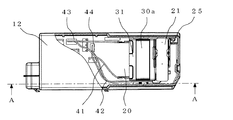
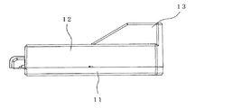
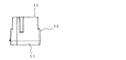
図2は大型電子部品収納ボックス10の斜視図、図3は大型電子部品収納ボックス10内部の一部分を示す平面図、図4は大型電子部品収納ボックス10の側面図、図5は図3のA−A断面側面図、図6は大型電子部品収納ボックス10の背面図である。また、図7はコンデンサー30を保持したホルダー31の斜視図、図8はホルダー31を後方側から見た斜視図、図9はプリント基板20の斜視図である。
2 is a perspective view of the large electronic
大型電子部品収納ボックス10は、下ケース11部分は全体的に略長方体形状で、上ケース12部分の中央部から後端部にかけて略直角台形状に隆起した凸部13を有する形状に形成されている。この略直角台形状の凸部13が、後述するコンデンサー等の大型電子部品を保持するホルダーが配置された部分を覆っている。この大型電子部品収納ボックス10の外形形状はそれが配置される除湿機本体101の下部隅部の設置スペースに合わせてある。
The large electronic
大型電子部品収納ボックス10は、ABS樹脂等により形成された、下ケース11と、下ケース11の蓋である上ケース12とを有する。下ケース11内には複数の支持リブ14が設けられており、この支持リブ14上にプリント基板20が取り付けられている。また、プリント基板20の外形に略合致するように下ケース11の内側面の輪郭形状が形成されている。つまり、下ケース11の内部スペースはほぼプリント基板20の大きさで占められる。
The large electronic
大型電子部品であるコンデンサー30は、ホルダー31に収納されている。ホルダー31は、コンデンサー30の収納部(電子部品収納部)32と、プリント基板20を跨いで下ケース11上に支持される2本の支持脚33、33とを有する。支持脚33、33は下ケース11とプリント基板20との間に差し込まれて支持されるようになっている。このため、コンデンサー30の重量負荷がプリント基板20にかからないので、落下や転倒時の衝撃を軽減することができる。
A
また、図3に示すように、1つのネジ25でプリント基板20を下ケース11に固定することにより、ホルダー31の支持脚33、33が固定される。すなわち、プリント基板20とホルダー31のネジ取付部34とを1つのネジ25の共締めで固定する構造となっている。このように構成することで、プリント基板20およびホルダー31の固定が容易かつ確実にできる。
Further, as shown in FIG. 3, the
ホルダー31の電子部品収納部32は、本例では2つ設けられているが、1つでもよいし、2つ以上でもよい。前側のコンデンサー30aは、先端裏側に設けられた爪35により前側コンデンサー30aの前面中央部を係止して抜けだしを防止している。後ろ側コンデンサー30bは別基板21の裏側に一体的に装着されており、後ろ側の電子部品収納部31に収納され、別基板21の上面部を前後2つの爪36で係止し抜け出しを防止している。前側コンデンサー30aと後ろ側コンデンサー30bは、それぞれリード線41、42が接続され、それぞれコネクター43、44を介してプリント基板20に接続されている。
また、ホルダー31はハーネス固定部37、38が形成されており、後ろ側コンデンサー30bのリード線42をハーネス固定部37、38に掛け回してバタツキを防ぐ構成となっている。
Two electronic
The
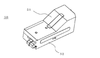
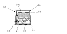
次に、延焼防止用カバー50について説明する。図10は延焼防止用カバー50で大型電子部品収納ボックス10を覆った状態を示す斜視図、図11は図10の側面図、図12は図11のB−B断面図、図13は図11のC−C断面図である。
Next, the fire
延焼防止用カバー50は、薄鋼板(例えば、溶融亜鉛メッキ鋼板)の板金加工により作られており、電子部品収納ボックス10を一方の側面開口部から挿入して全体をカバーするようになっている。したがって、延焼防止用カバー50は、一方の側面が開口されたカバー本体51と、その開口を塞ぐカバー側面板52とから構成されている。
この構成により、延焼を内部にとどめて他に及ぶことはないので安全である。
The fire spread
With this configuration, it is safe because the fire spread is not limited to the inside.
本実施の形態の大型電子部品収納ボックス10は、上記のように構成されているので、以下に示すような効果がある。
Since the large electronic
(1)大型電子部品のコンデンサー30はホルダー31に収納され、ホルダー31の支持脚33、33を下ケース11にて支えているので、コンデンサー30の重量負荷はプリント基板20にかからない。そのため、落下や転倒時の衝撃を軽減でき、プリント基板20や半田付部の損傷を抑制することができる。
(1) Since the
(2)ホルダー31は、プリント基板20と分離してコンデンサー30を保持するものであるため、プリント基板20を小さくすることができ、コンパクト化、省スペース化が可能である。また、省スペースのため、コンデンサー30のリード線41、42の長さを短くすることができる。
(2) Since the
(3)ホルダー31は、プリント基板20と共に下ケース11に少なくとも1つのネジ25で共締めすることにより固定されるので、プリント基板20およびホルダー31の固定が簡単かつ確実にできる。
(3) Since the
(4)ホルダー31にはハーネス固定部37、38が設けられ、ハーネス固定部37、38で後ろ側コンデンサー30bの比較的長い方のリード線42を固定しているので、リード線42のバタツキを抑制することができる。
(4) The
(5)大型電子部品収納ボックス10の全体を板金製の延焼防止用カバー50で覆っているため、延焼が他に及ぶことがない。
(5) Since the entire large-sized electronic
(6)後ろ側コンデンサー30bのようにプリント基板20とは別の基板21が取り付けられる場合は、ホルダー31はコンデンサー30bを収納し保持することにより、別基板21を押さえつけないようにしている。このように構成することにより、別基板21やその半田付部に余計な荷重が作用することがない。
(6) When a
(7)ホルダー31は、コンデンサー30aおよび別基板21付きコンデンサー30bを弾性的に係止する爪35、36を有するため、これらのコンデンサーを脱落することなく確実に保持することができる。
(7) Since the
(8)上ケース12を下ケース11の外側に被さるように嵌合することにより、水の侵入を防止することができる。
(8) By fitting the
(9)この大型電子部品収納ボックス10は、除湿機100の下部など低い位置に設置されているので、転倒時の衝撃を緩和することができる。
(9) Since the large electronic
実施の形態2.
本実施の形態では、上ケース12の凸部13内にコンデンサー30の保持部(不図示)を設けるものである。
このように構成することによっても、コンデンサー30の重量負荷がプリント基板20にかからないので、衝撃によるプリント基板20や半田付け部の損傷を抑制することができる。また、コンパクト化、省スペース化も実現できる。
Embodiment 2. FIG.
In the present embodiment, a holding portion (not shown) for the
With this configuration as well, since the weight load of the
実施の形態3.
図示は省略するが、本実施の形態では下ケース11の底部に凹部を形成し、この凹部をコンデンサー30の保持部とするものである。
この構成によっても、実施の形態2と同様な効果がある。
Embodiment 3 FIG.
Although illustration is omitted, in the present embodiment, a recess is formed in the bottom of the
This configuration also has the same effect as the second embodiment.
以上に説明した本発明の大型電子部品収納ボックスは、除湿機に限らず、洗濯機や冷蔵庫、洗濯乾燥機、空気清浄機、空調機などの家電製品に活用することができる。 The large electronic component storage box of the present invention described above can be used not only for a dehumidifier but also for home appliances such as a washing machine, a refrigerator, a washing dryer, an air purifier, and an air conditioner.
10 大型電子部品収納ボックス、11 下ケース、12 上ケース、13 凸部、14 支持リブ、20 プリント基板、21 別基板、25 ネジ、30 コンデンサー、31 ホルダー、32 電子部品収納部、33 支持脚、34 ネジ取付部、35、36 爪、37、38 ハーネス固定部、41、42 リード線、43、44 コネクター、50 延焼防止用カバー、51 カバー本体、52 カバー側面板、100 除湿機、101 除湿機本体、102 送風ファン、103 吹き出しグリル、104 操作部兼表示部、105 ドレン水タンク、110 前面パネル。 10 Large electronic component storage box, 11 Lower case, 12 Upper case, 13 Convex portion, 14 Support rib, 20 Printed circuit board, 21 Separate substrate, 25 Screw, 30 Capacitor, 31 Holder, 32 Electronic component storage portion, 33 Support leg, 34 Screw mounting part, 35, 36 Claw, 37, 38 Harness fixing part, 41, 42 Lead wire, 43, 44 Connector, 50 Cover for preventing fire spread, 51 Cover body, 52 Cover side plate, 100 Dehumidifier, 101 Dehumidifier Main body, 102 blower fan, 103 blowout grill, 104 operation unit / display unit, 105 drain water tank, 110 front panel.
Claims (11)
項1〜6のいずれかに記載の大型電子部品収納ボックス。 The large electronic component storage box according to claim 1, wherein the upper case is fitted so as to cover an outer side of the lower case.
Priority Applications (1)
| Application Number | Priority Date | Filing Date | Title |
|---|---|---|---|
| JP2010059119A JP5452298B2 (en) | 2010-03-16 | 2010-03-16 | Large electronic component storage box and home appliances equipped with the same |
Applications Claiming Priority (1)
| Application Number | Priority Date | Filing Date | Title |
|---|---|---|---|
| JP2010059119A JP5452298B2 (en) | 2010-03-16 | 2010-03-16 | Large electronic component storage box and home appliances equipped with the same |
Publications (3)
| Publication Number | Publication Date |
|---|---|
| JP2011191030A JP2011191030A (en) | 2011-09-29 |
| JP2011191030A5 JP2011191030A5 (en) | 2012-08-30 |
| JP5452298B2 true JP5452298B2 (en) | 2014-03-26 |
Family
ID=44796150
Family Applications (1)
| Application Number | Title | Priority Date | Filing Date |
|---|---|---|---|
| JP2010059119A Active JP5452298B2 (en) | 2010-03-16 | 2010-03-16 | Large electronic component storage box and home appliances equipped with the same |
Country Status (1)
| Country | Link |
|---|---|
| JP (1) | JP5452298B2 (en) |
Families Citing this family (2)
| Publication number | Priority date | Publication date | Assignee | Title |
|---|---|---|---|---|
| JP6315280B2 (en) * | 2015-01-30 | 2018-04-25 | 株式会社富士通ゼネラル | Control device |
| CN105163538B (en) * | 2015-10-15 | 2018-06-08 | 珠海格力电器股份有限公司 | Electric appliance case assembly and air purifier |
Family Cites Families (11)
| Publication number | Priority date | Publication date | Assignee | Title |
|---|---|---|---|---|
| JPS6125533Y2 (en) * | 1981-02-18 | 1986-08-01 | ||
| JPH04278596A (en) * | 1991-03-06 | 1992-10-05 | Mitsubishi Electric Corp | Mounting auxiliary device for chip-shaped electronic component |
| JPH06147550A (en) * | 1992-11-13 | 1994-05-27 | Sanyo Electric Co Ltd | Outdoor unit for air conditioner |
| JPH08261508A (en) * | 1995-03-20 | 1996-10-11 | Fujitsu General Ltd | Outdoor machine for air-conditioner |
| JP3455386B2 (en) * | 1997-01-22 | 2003-10-14 | 三菱電機株式会社 | Inverter control circuit device for air conditioner |
| JPH11211154A (en) * | 1998-01-20 | 1999-08-06 | Sanyo Electric Co Ltd | Outdoor machine of air conditioner |
| JPH11211155A (en) * | 1998-01-29 | 1999-08-06 | Daikin Ind Ltd | Electric equipment box and casing |
| JP3570880B2 (en) * | 1998-02-10 | 2004-09-29 | 株式会社荏原電産 | Power control module |
| JP4410496B2 (en) * | 2003-06-13 | 2010-02-03 | 富士通株式会社 | Speaker support device and electronic apparatus |
| JP2005133996A (en) * | 2003-10-29 | 2005-05-26 | Hitachi Home & Life Solutions Inc | Electric component for air conditioner |
| JP2008071854A (en) * | 2006-09-13 | 2008-03-27 | Daikin Ind Ltd | Electrical component case structure |
-
2010
- 2010-03-16 JP JP2010059119A patent/JP5452298B2/en active Active
Also Published As
| Publication number | Publication date |
|---|---|
| JP2011191030A (en) | 2011-09-29 |
Similar Documents
| Publication | Publication Date | Title |
|---|---|---|
| US9444157B2 (en) | Connector and refrigerator including the same | |
| WO2016067897A1 (en) | Electricity storage unit | |
| JP5452298B2 (en) | Large electronic component storage box and home appliances equipped with the same | |
| JPWO2006068147A1 (en) | Air conditioner outdoor unit | |
| US6378320B1 (en) | Condenser unit for air conditioner or heat pump | |
| KR102131255B1 (en) | A controlbox of out-door unit for air conditioner | |
| JP2009021315A (en) | Structure of power cord pull-out section in electrical machinery and apparatus | |
| JP5293567B2 (en) | Duct type air conditioner | |
| JP2011191030A5 (en) | ||
| JP6377952B2 (en) | Alarm | |
| JP2018115797A (en) | refrigerator | |
| JP2012154565A (en) | Outdoor unit of air conditioner | |
| US10962276B2 (en) | Household appliance cabinet ground connection | |
| JP5015212B2 (en) | Noise filter | |
| JP4175170B2 (en) | Electrical component and outdoor unit using it | |
| KR102100659B1 (en) | Control box of air conditioner | |
| JP6664202B2 (en) | Harmonic suppression device and air conditioner using the same | |
| JP6902638B2 (en) | Harmonic suppressor and air conditioner using it | |
| US20150077925A1 (en) | Set top box having removable hard drive | |
| KR100568212B1 (en) | Refrigerator | |
| KR20170003148U (en) | Assembly Shelf with Wall-Hanging Body | |
| JP2002162158A (en) | Refrigerator | |
| KR200146085Y1 (en) | Out-door machine of airconditioner | |
| WO2020075243A1 (en) | Outdoor unit for air conditioner | |
| JPH02110221A (en) | Air conditioner |
Legal Events
| Date | Code | Title | Description |
|---|---|---|---|
| A521 | Request for written amendment filed |
Free format text: JAPANESE INTERMEDIATE CODE: A523 Effective date: 20120717 |
|
| A621 | Written request for application examination |
Free format text: JAPANESE INTERMEDIATE CODE: A621 Effective date: 20120717 |
|
| A977 | Report on retrieval |
Free format text: JAPANESE INTERMEDIATE CODE: A971007 Effective date: 20130712 |
|
| A131 | Notification of reasons for refusal |
Free format text: JAPANESE INTERMEDIATE CODE: A131 Effective date: 20130723 |
|
| A521 | Request for written amendment filed |
Free format text: JAPANESE INTERMEDIATE CODE: A523 Effective date: 20130905 |
|
| TRDD | Decision of grant or rejection written | ||
| A01 | Written decision to grant a patent or to grant a registration (utility model) |
Free format text: JAPANESE INTERMEDIATE CODE: A01 Effective date: 20131203 |
|
| A61 | First payment of annual fees (during grant procedure) |
Free format text: JAPANESE INTERMEDIATE CODE: A61 Effective date: 20131227 |
|
| R150 | Certificate of patent or registration of utility model |
Ref document number: 5452298 Country of ref document: JP Free format text: JAPANESE INTERMEDIATE CODE: R150 Free format text: JAPANESE INTERMEDIATE CODE: R150 |
|
| R250 | Receipt of annual fees |
Free format text: JAPANESE INTERMEDIATE CODE: R250 |
|
| R250 | Receipt of annual fees |
Free format text: JAPANESE INTERMEDIATE CODE: R250 |
|
| R250 | Receipt of annual fees |
Free format text: JAPANESE INTERMEDIATE CODE: R250 |
|
| R250 | Receipt of annual fees |
Free format text: JAPANESE INTERMEDIATE CODE: R250 |
|
| R250 | Receipt of annual fees |
Free format text: JAPANESE INTERMEDIATE CODE: R250 |
|
| R250 | Receipt of annual fees |
Free format text: JAPANESE INTERMEDIATE CODE: R250 |
|
| R250 | Receipt of annual fees |
Free format text: JAPANESE INTERMEDIATE CODE: R250 |
|
| R250 | Receipt of annual fees |
Free format text: JAPANESE INTERMEDIATE CODE: R250 |