JP5452000B2 - Image forming apparatus - Google Patents
Image forming apparatus Download PDFInfo
- Publication number
- JP5452000B2 JP5452000B2 JP2008218799A JP2008218799A JP5452000B2 JP 5452000 B2 JP5452000 B2 JP 5452000B2 JP 2008218799 A JP2008218799 A JP 2008218799A JP 2008218799 A JP2008218799 A JP 2008218799A JP 5452000 B2 JP5452000 B2 JP 5452000B2
- Authority
- JP
- Japan
- Prior art keywords
- voltage
- image forming
- adjustment
- developing roller
- unit
- Prior art date
- Legal status (The legal status is an assumption and is not a legal conclusion. Google has not performed a legal analysis and makes no representation as to the accuracy of the status listed.)
- Expired - Fee Related
Links
Images

Landscapes
- Developing For Electrophotography (AREA)
- Control Or Security For Electrophotography (AREA)
- Color Electrophotography (AREA)
Description
本発明は、複写機、プリンタ、ファクシミリ等の画像形成装置に関する。 The present invention relates to an image forming apparatus such as a copying machine, a printer, and a facsimile.
従来から、複写機、プリンタ、ファクシミリ等のトナーを用いる画像形成装置では、感光体ドラムとこれに対向する現像ローラとが設けられることがある。そして、現像ローラには、直流と交流が重畳された、いわゆる現像バイアスが印加される。これにより、帯電したトナーが現像ローラから感光体ドラムに飛翔し、静電潜像が現像される。 Conventionally, in an image forming apparatus using toner such as a copying machine, a printer, and a facsimile machine, a photosensitive drum and a developing roller facing the photosensitive drum may be provided. A so-called developing bias in which direct current and alternating current are superimposed is applied to the developing roller. As a result, the charged toner flies from the developing roller to the photosensitive drum, and the electrostatic latent image is developed.
ここで、十分にトナーを感光体ドラムに供給し、形成される画像の濃度を確保し、現像効率を高めるには、現像ローラに印加する交流電圧のピーク間電圧(ピークトゥピーク)を大きくすればよいが、大きくしすぎると感光体ドラムと現像ローラ間のギャップで放電が発生する。放電が発生すると、感光体ドラム表面の電位変化により静電潜像が乱れ、形成される画像の品質が劣化する。又、感光体ドラムの特性によって、放電電流の流れる方向により、大電流が流れ、感光体ドラムの損傷を引き起こす場合がある。従って、放電の生ずるような交流電圧を、画像形成時に現像ローラに印加すべきではない。 Here, in order to sufficiently supply the toner to the photosensitive drum, to ensure the density of the formed image and to improve the development efficiency, the peak-to-peak voltage of the AC voltage applied to the developing roller should be increased. However, if it is too large, discharge occurs in the gap between the photosensitive drum and the developing roller. When the discharge occurs, the electrostatic latent image is disturbed due to the potential change on the surface of the photosensitive drum, and the quality of the formed image is deteriorated. Further, depending on the characteristics of the photosensitive drum, a large current may flow depending on the direction in which the discharge current flows, causing damage to the photosensitive drum. Accordingly, an AC voltage that causes discharge should not be applied to the developing roller during image formation.
そこで、例えば、特許文献1には、像担持体と現像領域において所要間隔を介して対向するトナー担持体を設け、このトナー担持体と像担持体との間に直流電圧と交流電圧とが重畳された現像バイアス電圧を印加させて、トナーを像担持体に供給して静電潜像を現像する現像装置において、像担持体とトナー担持体との間に印加させるリーク検知電圧を変化させるリーク発生手段と、リークを検知するリーク検知手段とを設け、リーク検知電圧と像担持体の表面電位との最大の電位差ΔVmaxを徐々に増加させて、像担持体とトナー担持体との間に流れる電流が連続して増加した場合、リーク検知手段によってリークと判断する現像装置が記載されている(例えば、特許文献1:請求項1等参照)。
上述したように、放電による弊害を生じさせず、トナーを十分飛翔させて現像効率を高めるには、感光体ドラムと現像ローラ間での放電が発生せず、かつ、できる限り大きい交流電圧を現像ローラに印加することになる。ここで、放電発生の有無には、現像ローラと感光体ドラムとのギャップ(隙間)の長さが、大きく関係する。しかし、このギャップ長は、感光体ドラムや現像ローラの取付、支持における誤差のため、各画像形成装置で異なる。又、放電が生ずる電位差は、気圧などの影響を受け変動する。従って、放電が生ずる電位差は、各画像形成装置や設置環境等で異なる。そのため、例えば、工場での製品検査時や、製品の設置時等に放電が発生せず、かつ、できる限り(ピーク間が)大きい交流電圧の初期設定がなされる。特許文献1は、この設定の1形態を示すと認められる。
As described above, in order to increase the development efficiency by causing toner to fly sufficiently without causing adverse effects due to discharge, no discharge occurs between the photosensitive drum and the developing roller, and an AC voltage as large as possible is developed. It will be applied to the roller. Here, the length of the gap between the developing roller and the photosensitive drum is largely related to whether or not discharge is generated. However, this gap length differs in each image forming apparatus due to an error in mounting and supporting the photosensitive drum and the developing roller. In addition, the potential difference at which discharge occurs varies under the influence of atmospheric pressure and the like. Therefore, the potential difference at which discharge occurs varies depending on each image forming apparatus, installation environment, and the like. For this reason, for example, when a product is inspected at a factory or when a product is installed, an AC voltage is initially set as large as possible (between peaks) without discharge.
しかし、感光体ドラムや現像ローラの使用による経時変化のため、放電が発生する交流電圧の大きさが変化する場合がある。例えば、設置環境等での画像形成装置への衝撃や、ジャム処理やメンテナンスで感光体ドラム等に力が加えられることや、感光体ドラムや現像ローラの表面の摩耗等で、ギャップ長が微妙に変わる場合がある。又、感光体ドラムの感光層劣化や、現像ローラへの交流電圧印加回路の劣化や、感光体ドラムを帯電させる帯電装置の帯電能力の低下等の経年劣化も要因となり得る。又、設置環境での気圧、気温、湿度の大きな変化等も放電が発生する交流電圧の大きさを変化させる場合もある。即ち、製品検査時等の時点で、画像形成時に印加する交流電圧が最適となるように設定しても、これらの経時変化的な要因のため、現状では、放電が発生し、又は、現像効率が低くなっている場合があるという問題がある。 However, due to changes over time due to the use of the photosensitive drum and the developing roller, the magnitude of the alternating voltage at which discharge occurs may change. For example, the gap length is subtle due to the impact on the image forming apparatus in the installation environment, the application of force to the photosensitive drum during jamming and maintenance, and the wear on the surface of the photosensitive drum and developing roller. May change. In addition, deterioration of the photosensitive layer of the photosensitive drum, deterioration of an AC voltage application circuit to the developing roller, and deterioration of the charging ability of the charging device for charging the photosensitive drum may be factors. In addition, large changes in atmospheric pressure, temperature, and humidity in the installation environment may change the magnitude of the alternating voltage at which discharge occurs. In other words, even if the AC voltage applied at the time of image formation is set to be optimal at the time of product inspection or the like, at present, discharge occurs or development efficiency due to these time-dependent factors. There is a problem that may be low.
従って、画像形成時に印加する交流電圧の設定を、経時変化に応じて調整していく必要があるが、特許文献1記載の発明のように、最大の電位差ΔVmaxを徐々に増加させ、電流が連続して増加した場合、リーク検知手段によってリークと判断すると(特許文献1:請求項1等参照)、リーク発生と判断するまで非常に長い時間がかかる問題がある(例えば、リーク発生電圧が、設定可能な上限値に近い場合等)。特に、カラー機で感光体ドラムと現像ローラの組み合わせを複数有する場合(例えば、タンデム式)、各色について調整を行うと非常に長い時間がかかる。そして、この間、使用者は、画像形成装置を使用できず、使用者の利便性及び画像形成装置の生産性を損なうという問題がある。
Therefore, it is necessary to adjust the setting of the AC voltage applied at the time of image formation according to the change over time. However, as in the invention described in
本発明は、上記問題点を鑑み、経時変化により、画像形成時に印加する現像ローラに印加する交流電圧の調整が必要な場合、簡易かつ高効率に、使用者の利便性、画像形成装置の生産性を損わず、画像形成時に印加する交流電圧の調整を行うことを課題とする。 In view of the above problems, the present invention is simple and highly efficient for the convenience of the user and the production of the image forming apparatus when it is necessary to adjust the AC voltage applied to the developing roller applied during image formation due to changes over time. It is an object to adjust the AC voltage applied during image formation without impairing the properties.
上記目的を達成するために請求項1に係る画像形成装置は、周面にトナー像を担持する感光体ドラムと、前記感光体ドラムにギャップが設けられつつ対向し、画像形成時にトナーを担持し、前記感光体ドラムへのトナーの供給のため、交流電圧印加部が接続される現像ローラとを含み、それぞれ色の異なるトナー像を形成する複数の画像形成部と、データを記憶する記憶部と、前記現像ローラと前記感光体ドラム間での放電発生を検出する検出部と、装置の各部を制御するとともに、前記検出部の出力が入力され放電発生を認識する制御部と、を有し、前記制御部は、前記現像ローラに印加する交流電圧を変化させつつ放電の発生の有無を確認して、前記現像ローラに印加する交流電圧の調整を所定のタイミングで実行し、1回の前記調整では、1つの前記画像形成部に対してのみ前記調整を行うように制御することとした。 In order to achieve the above object, an image forming apparatus according to a first aspect of the present invention opposes a photosensitive drum carrying a toner image on a peripheral surface thereof while providing a gap in the photosensitive drum, and carries the toner during image formation. A plurality of image forming units for forming toner images of different colors, and a storage unit for storing data, including a developing roller connected to an AC voltage application unit for supplying toner to the photosensitive drum. A detection unit that detects the occurrence of discharge between the developing roller and the photosensitive drum; and a control unit that controls each unit of the apparatus and that receives the output of the detection unit and recognizes the occurrence of discharge. The controller checks whether or not discharge has occurred while changing the AC voltage applied to the developing roller, executes adjustment of the AC voltage applied to the developing roller at a predetermined timing, and performs the adjustment once. so , It was decided to control to perform the adjustment for only one of the image forming unit.
この構成によれば、1回の調整では、1つの画像形成部に対してのみ調整を行うので、全色の画像形成部に対して調整を行う場合に比べ、迅速に調整が終了する。従って、使用者の利便性や画像形成装置の生産性を大きく損なうことがない。又、経時変化では、現像ローラに印加する最適な交流電圧が変化しても劇的な変化は通常なく、1回の調整で1つの画像形成部に対してのみ調整を行うとしても、十分に、現像効率は、高い状態で維持され、画像の濃度が維持された高画質の画像形成装置を提供することができる。 According to this configuration, since the adjustment is performed only for one image forming unit in one adjustment, the adjustment is completed more quickly than in the case where the adjustment is performed for the image forming units of all colors. Therefore, user convenience and productivity of the image forming apparatus are not greatly impaired. In addition, even if the optimum AC voltage applied to the developing roller changes, there is usually no dramatic change with time, and even if only one image forming unit is adjusted by one adjustment, it is sufficient. Further, it is possible to provide a high-quality image forming apparatus in which the development efficiency is maintained in a high state and the image density is maintained.
又、前記制御部は、調整を行う前記画像形成部の順番の1周分の回数を前記画像形成部の総数とし、前記1周分の回数の間に各画像形成部に対し1回ずつ前記調整が実行されるように、前記調整を行う前記画像形成部の順番を決定し、かつ、前記1周内での前記調整を行う前記画像形成部の順番を固定しないこととした。更に、各前記画像形成部を使用履歴を示す履歴データが、前記記憶部に記憶され、2周目以降の前記調整時、前記制御部は、前記履歴データに基づき、前周での前記調整から現在までの使用時間の長い前記画像形成部から、前記調整を行うこととした。
Further, the prior SL controller, the number of one round of the order of the image forming unit for adjusting a total number of said image forming unit, once for each image forming unit during the number of the one rotation The order of the image forming units that perform the adjustment is determined so that the adjustment is performed, and the order of the image forming units that perform the adjustment within the one round is not fixed. Further, history data indicating a use history of each of the image forming units is stored in the storage unit, and at the time of the adjustment after the second round, the control unit starts from the adjustment in the previous cycle based on the history data. The adjustment is performed from the image forming unit that has been used for a long time.
この構成では、1周分の回数の間に、各画像形成部に対し1回ずつ調整が実行されるので、全ての画像形成部は、万遍なく調整の対象となる。又、1周分の間での調整を行う画像形成部の順番を固定しないので、例えば、使用頻度の高い画像形成部等の各種事情を考慮して、調整を行う画像形成部の順番を決定することができる。更に、この構成では、履歴データに基づき、前周での調整時から現在までの使用時間の長い画像形成部から、調整を行うので、前回の調整からの使用時間が長く(例えば、白黒画像を頻繁に印刷する場合など)、経時変化の影響が大きく現れやすい画像形成部に対し優先的に調整を行うことができる。言い換えると、経時変化の影響が現れ難く、あまり使用されない画像形成部を後回しにすることができる。従って、画像形成時に印加する交流電圧について、効率よく経時変化に対する調整を行うができ、画像形成装置の状況に応じた交流電圧の設定を行うことができる。
In this configuration, since the adjustment is performed once for each image forming unit during the number of times of one round, all the image forming units are uniformly subject to adjustment. In addition, since the order of the image forming units to be adjusted for one round is not fixed, for example, the order of the image forming units to be adjusted is determined in consideration of various circumstances such as frequently used image forming units. can do. Furthermore, in this configuration, since the adjustment is performed from the image forming unit having a long use time from the adjustment on the previous circumference to the present based on the history data, the use time from the previous adjustment is long (for example, a black and white image is For example, when printing is frequently performed), it is possible to preferentially adjust an image forming unit that is likely to be greatly affected by changes over time. In other words, it is possible to postpone an image forming unit that is less likely to be affected by changes over time and is not often used. Therefore, the AC voltage applied during image formation can be efficiently adjusted for changes over time, and the AC voltage can be set according to the status of the image forming apparatus.
又、請求項2に係る発明は、請求項1記載の発明において、前記記憶部には、前記調整時、現在、画像形成時に前記現像ローラに印加する交流電圧の大きさに応じ、最初に前記現像ローラに印加すべき交流電圧に関する設定データが記憶され、前記調整時、前記制御部は、前記設定データに基づき、前記交流電圧印加部に前記現像ローラに交流電圧を印加させ、放電の発生を認識した場合、前記制御部は、画像形成時に前記現像ローラに印加する交流電圧を小さくさせるとともに、前記設定データを更新し、放電の発生の認識しない場合、前記制御部は、画像形成時に前記現像ローラに印加する交流電圧を大きく又は現状維持させるとともに、画像形成時の交流電圧を大きくする場合のみ前記設定データを更新することとした。
According to a second aspect of the present invention, in the first aspect of the present invention, the storage unit first includes the storage unit according to a magnitude of an AC voltage applied to the developing roller at the time of the adjustment and at the time of image formation. Setting data relating to an AC voltage to be applied to the developing roller is stored, and at the time of the adjustment, the control unit causes the AC voltage applying unit to apply an AC voltage to the developing roller based on the setting data to generate a discharge. If recognized, the control unit reduces the AC voltage applied to the developing roller during image formation and updates the setting data. If the generation of discharge is not recognized, the control unit performs the development during image formation. The setting data is updated only when the AC voltage applied to the roller is increased or maintained as it is and the AC voltage during image formation is increased.
この構成によれば、画像形成時に現像ローラに印加すべき交流電圧を、放電が生じず、かつ、現像効率が高い状態で維持でき、濃度等の変動が少なく、形成される画像の品質画像形成装置を提供することができる。 According to this configuration, the AC voltage to be applied to the developing roller at the time of image formation can be maintained in a state where no discharge occurs and the development efficiency is high, and there is little variation in density and the like. An apparatus can be provided.
又、請求項3に係る画像形成装置は、周面にトナー像を担持する感光体ドラムと、前記感光体ドラムにギャップが設けられつつ対向し、画像形成時にトナーを担持し、前記感光体ドラムへのトナーの供給のため、交流電圧印加部が接続される現像ローラとを含み、それぞれ色の異なるトナー像を形成する複数の画像形成部と、データを記憶する記憶部と、前記現像ローラと前記感光体ドラム間での放電発生を検出する検出部と、装置の各部を制御するとともに、前記検出部の出力が入力され放電発生を認識する制御部と、を有し、前記交流電圧印加部及び前記検出部は前記画像形成部ごとに設けられ、前記記憶部には、前記調整時、現在、画像形成時に前記現像ローラに印加する交流電圧の大きさに応じ、最初に前記現像ローラに印加すべき交流電圧に関する設定データが記憶され、前記制御部は、前記現像ローラに印加する交流電圧を変化させつつ放電の発生の有無を確認して画像形成時に前記現像ローラに印加すべき交流電圧を決定する調整を所定のタイミングで実行し、1回の前記調整では、1つの前記画像形成部に対してのみ前記調整を行うように制御し、調整を行う前記画像形成部の順番の1周分の回数を前記画像形成部の総数とし、前記1周分の回数の間に各画像形成部に対し1回ずつ前記調整が実行されるように、前記調整を行う前記画像形成部の順番を決定し、かつ、前記1周内での前記調整を行う前記画像形成部の順番を固定せず、前記調整時、前記設定データに基づき、前記交流電圧印加部に前記現像ローラに交流電圧を印加させ、放電の発生を認識した場合、前記制御部は、画像形成時に前記現像ローラに印加する交流電圧を小さくさせるとともに、前記設定データを更新し、放電の発生の認識しない場合、前記制御部は、画像形成時に前記現像ローラに印加する交流電圧を大きく又は現状維持させるとともに、画像形成時の交流電圧を大きくする場合のみ前記設定データを更新し、2周目以降の前記調整時、前周の前記調整で画像形成時に前記現像ローラに印加する交流電圧の大きさの変更があった場合、前記制御部は、画像形成時に印加する交流電圧の変更があった前記画像形成部から、前記調整を行うこととした。
According to a third aspect of the present invention, there is provided an image forming apparatus comprising: a photosensitive drum carrying a toner image on a peripheral surface thereof; the photosensitive drum is opposed to the photosensitive drum while providing a gap; A plurality of image forming units that form toner images of different colors, a storage unit that stores data, and the developing roller. A detection unit that detects the occurrence of discharge between the photosensitive drums; and a control unit that controls each unit of the apparatus and that receives the output of the detection unit and recognizes the occurrence of discharge. And the detection unit is provided for each image forming unit, and the storage unit is first applied to the developing roller according to the magnitude of the AC voltage applied to the developing roller at the time of the adjustment and at the time of image formation. should Setting data relating to the flow voltage is stored, and the control unit determines whether or not discharge has occurred while changing the AC voltage applied to the developing roller, and determines the AC voltage to be applied to the developing roller during image formation. Adjustment is executed at a predetermined timing, and in one adjustment, control is performed so that the adjustment is performed only on one image forming unit, and the number of times of one turn in the order of the image forming units to be adjusted The order of the image forming units to perform the adjustment is determined so that the adjustment is performed once for each image forming unit during the number of times of the one round. Further, the order of the image forming units that perform the adjustment within the one circumference is not fixed, and during the adjustment, the AC voltage application unit applies an AC voltage to the developing roller based on the setting data, and discharge is performed. When recognizing the occurrence of The control unit reduces the AC voltage applied to the developing roller during image formation and updates the setting data. When the controller does not recognize the occurrence of discharge, the control unit applies to the developing roller during image formation. The setting data is updated only when the AC voltage is increased or maintained as it is, and the AC voltage is increased during image formation. When there is a change in the magnitude of the AC voltage to be applied, the control unit performs the adjustment from the image forming unit in which the AC voltage applied during image formation has been changed.
この構成によれば、1回の調整では、1つの画像形成部に対してのみ調整を行うので、全色の画像形成部に対して調整を行う場合に比べ、迅速に調整が終了する。従って、使用者の利便性や画像形成装置の生産性を大きく損なうことがない。又、経時変化では、現像ローラに印加する最適な交流電圧が変化しても劇的な変化は通常なく、1回の調整で1つの画像形成部に対してのみ調整を行うとしても、十分に、現像効率は、高い状態で維持され、画像の濃度が維持された高画質の画像形成装置を提供することができる。又、この構成では、1周分の回数の間に、各画像形成部に対し1回ずつ調整が実行されるので、全ての画像形成部は、万遍なく調整の対象となる。又、1周分の間での調整を行う画像形成部の順番を固定しないので、例えば、使用頻度の高い画像形成部等の各種事情を考慮して、調整を行う画像形成部の順番を決定することができる。又、この構成によれば、画像形成時に現像ローラに印加すべき交流電圧を、放電が生じず、かつ、現像効率が高い状態で維持でき、濃度等の変動が少なく、形成される画像の品質画像形成装置を提供することができる。更に、この構成では、制御部は、画像形成時に印加する交流電圧の変更があった画像形成部から調整を行うので、前回の交流電圧の調整(変更)が正しいか、早い段階で確認することができる。従って、もし、前回の交流電圧の調整が誤りであれば速やかに再調整されることになる。
According to this configuration, since the adjustment is performed only for one image forming unit in one adjustment, the adjustment is completed more quickly than in the case where the adjustment is performed for the image forming units of all colors. Therefore, user convenience and productivity of the image forming apparatus are not greatly impaired. In addition, even if the optimum AC voltage applied to the developing roller changes, there is usually no dramatic change with time, and even if only one image forming unit is adjusted by one adjustment, it is sufficient. Further, it is possible to provide a high-quality image forming apparatus in which the development efficiency is maintained in a high state and the image density is maintained. Further, in this configuration, since the adjustment is performed once for each image forming unit during the number of times of one round, all the image forming units are uniformly subject to adjustment. In addition, since the order of the image forming units to be adjusted for one round is not fixed, for example, the order of the image forming units to be adjusted is determined in consideration of various circumstances such as frequently used image forming units. can do. In addition, according to this configuration, the AC voltage to be applied to the developing roller during image formation can be maintained in a state in which no discharge occurs and development efficiency is high, and there is little variation in density and the quality of the formed image. An image forming apparatus can be provided. Further, in this configuration, since the control unit performs adjustment from the image forming unit in which the AC voltage applied during image formation has been changed, it is confirmed at an early stage whether the previous adjustment (change) of the AC voltage is correct. Can do. Therefore, if the previous adjustment of the AC voltage is incorrect, it will be readjusted promptly.
又、請求項4に係る画像形成装置は、周面にトナー像を担持する感光体ドラムと、前記感光体ドラムにギャップが設けられつつ対向し、画像形成時にトナーを担持し、前記感光体ドラムへのトナーの供給のため、交流電圧印加部が接続される現像ローラとを含み、それぞれ色の異なるトナー像を形成する複数の画像形成部と、データを記憶する記憶部と、前記現像ローラと前記感光体ドラム間での放電発生を検出する検出部と、装置の各部を制御するとともに、前記検出部の出力が入力され放電発生を認識する制御部と、を有し、前記交流電圧印加部及び前記検出部は前記画像形成部ごとに設けられ、前記記憶部には、前記調整時、現在、画像形成時に前記現像ローラに印加する交流電圧の大きさに応じ、最初に前記現像ローラに印加すべき交流電圧に関する設定データが記憶され、前記制御部は、前記現像ローラに印加する交流電圧を変化させつつ放電の発生の有無を確認して画像形成時に前記現像ローラに印加すべき交流電圧を決定する調整を所定のタイミングで実行し、1回の前記調整では、1つの前記画像形成部に対してのみ前記調整を行うように制御し、調整を行う前記画像形成部の順番の1周分の回数を前記画像形成部の総数とし、前記1周分の回数の間に各画像形成部に対し1回ずつ前記調整が実行されるように、前記調整を行う前記画像形成部の順番を決定し、かつ、前記1周内での前記調整を行う前記画像形成部の順番を固定せず、前記調整時、前記設定データに基づき、前記交流電圧印加部に前記現像ローラに交流電圧を印加させ、放電の発生を認識した場合、前記制御部は、画像形成時に前記現像ローラに印加する交流電圧を小さくさせるとともに、前記設定データを更新し、放電の発生の認識しない場合、前記制御部は、画像形成時に前記現像ローラに印加する交流電圧を大きく又は現状維持させるとともに、画像形成時の交流電圧を大きくする場合のみ前記設定データを更新し、2周目以降の前記調整時、前記制御部は、所定回数にわたって、前記調整を行っても画像形成時に印加する交流電圧の変更のない前記画像形成部の前記調整を1又は複数周とばすこととした。
According to a fourth aspect of the present invention, there is provided an image forming apparatus comprising: a photosensitive drum carrying a toner image on a peripheral surface thereof; the photosensitive drum is opposed to the photosensitive drum while providing a gap; A plurality of image forming units that form toner images of different colors, a storage unit that stores data, and the developing roller. A detection unit that detects the occurrence of discharge between the photosensitive drums; and a control unit that controls each unit of the apparatus and that receives the output of the detection unit and recognizes the occurrence of discharge. And the detection unit is provided for each image forming unit, and the storage unit is first applied to the developing roller according to the magnitude of the AC voltage applied to the developing roller at the time of the adjustment and at the time of image formation. should Setting data relating to the flow voltage is stored, and the control unit determines whether or not discharge has occurred while changing the AC voltage applied to the developing roller, and determines the AC voltage to be applied to the developing roller during image formation. Adjustment is executed at a predetermined timing, and in one adjustment, control is performed so that the adjustment is performed only on one image forming unit, and the number of times of one turn in the order of the image forming units to be adjusted The order of the image forming units to perform the adjustment is determined so that the adjustment is performed once for each image forming unit during the number of times of the one round. Further, the order of the image forming units that perform the adjustment within the one circumference is not fixed, and during the adjustment, the AC voltage application unit applies an AC voltage to the developing roller based on the setting data, and discharge is performed. When recognizing the occurrence of The control unit reduces the AC voltage applied to the developing roller during image formation and updates the setting data. When the controller does not recognize the occurrence of discharge, the control unit applies to the developing roller during image formation. The setting data is updated only when the AC voltage is increased or maintained at the same time and the AC voltage at the time of image formation is increased. During the adjustment after the second round, the control unit performs the adjustment for a predetermined number of times. However, the adjustment of the image forming unit without changing the AC voltage applied at the time of image formation is skipped over one or more rounds.
この構成によれば、1回の調整では、1つの画像形成部に対してのみ調整を行うので、全色の画像形成部に対して調整を行う場合に比べ、迅速に調整が終了する。従って、使用者の利便性や画像形成装置の生産性を大きく損なうことがない。又、経時変化では、現像ローラに印加する最適な交流電圧が変化しても劇的な変化は通常なく、1回の調整で1つの画像形成部に対してのみ調整を行うとしても、十分に、現像効率は、高い状態で維持され、画像の濃度が維持された高画質の画像形成装置を提供することができる。又、この構成では、1周分の回数の間に、各画像形成部に対し1回ずつ調整が実行されるので、全ての画像形成部は、万遍なく調整の対象となる。又、1周分の間での調整を行う画像形成部の順番を固定しないので、例えば、使用頻度の高い画像形成部等の各種事情を考慮して、調整を行う画像形成部の順番を決定することができる。又、この構成によれば、画像形成時に現像ローラに印加すべき交流電圧を、放電が生じず、かつ、現像効率が高い状態で維持でき、濃度等の変動が少なく、形成される画像の品質画像形成装置を提供することができる。更に、この構成では、所定回数にわたって、前記調整後に、画像形成時に印加する交流電圧の変更がない場合、調整の必要性が少なく、しばらく調整を行わなくても画質の劣化が現れ難いと予測できるので、その色の調整を1又は複数周とばし、例えば、使用頻度が高い画像形成部等、調整の必要性が高い画像形成部での調整の頻度を増やすことができる。
According to this configuration, since the adjustment is performed only for one image forming unit in one adjustment, the adjustment is completed more quickly than in the case where the adjustment is performed for the image forming units of all colors. Therefore, user convenience and productivity of the image forming apparatus are not greatly impaired. In addition, even if the optimum AC voltage applied to the developing roller changes, there is usually no dramatic change with time, and even if only one image forming unit is adjusted by one adjustment, it is sufficient. Further, it is possible to provide a high-quality image forming apparatus in which the development efficiency is maintained in a high state and the image density is maintained. Further, in this configuration, since the adjustment is performed once for each image forming unit during the number of times of one round, all the image forming units are uniformly subject to adjustment. In addition, since the order of the image forming units to be adjusted for one round is not fixed, for example, the order of the image forming units to be adjusted is determined in consideration of various circumstances such as frequently used image forming units. can do. In addition, according to this configuration, the AC voltage to be applied to the developing roller during image formation can be maintained in a state in which no discharge occurs and development efficiency is high, and there is little variation in density and the quality of the formed image. An image forming apparatus can be provided. Further, in this configuration, if there is no change in the AC voltage applied at the time of image formation after the adjustment for a predetermined number of times, the necessity for adjustment is small, and it can be predicted that deterioration in image quality does not easily occur without adjustment for a while. Therefore, the adjustment of the color can be skipped one or more times, and the frequency of adjustment in an image forming unit having a high necessity for adjustment, such as an image forming unit having a high use frequency, can be increased.
又、請求項5に係る発明は、請求項1乃至4の発明において、主電源投入後の立上時、前回の調整から所定枚数印刷を行った時、画像形成開始時、画像形成が終了してから画像形成の指示がない状態が所定時間継続した時のいずれか、若しくは、これらの時の複数の組み合わせを実行タイミングとして、前記制御部は、前記調整を行うこととした。 According to a fifth aspect of the present invention, in the first to fourth aspects of the invention, at the start-up after the main power supply is turned on, when a predetermined number of sheets have been printed since the previous adjustment, the image formation is completed at the start of image formation. Then, the control unit performs the adjustment by using any one of the cases where no image forming instruction has continued for a predetermined time or a plurality of combinations at these times as the execution timing.
この構成では、主電源投入後の立ち上げ時、前回の調整から所定枚数印刷を行った時、画像形成開始時、画像形成が終了してから画像形成の指示がない状態が所定時間継続した時など、大きな経時変化が生じうる場合や、使用者が使用していない、或いは、できない状態に、調整を行うので、画質は維持され、又、使用者の利便性、画像形成装置の生産性の低下がない。 In this configuration, when the main power is turned on, when a predetermined number of sheets have been printed since the previous adjustment, when image formation is started, and when there is no image formation instruction after image formation has been completed for a predetermined time For example, the image quality is maintained because the adjustment is performed when a large change with time may occur, or when the user does not use or cannot use the image, and the convenience of the user and the productivity of the image forming apparatus are improved. There is no decline.
上述の通り、本発明によれば、簡易かつ高効率に、使用者の利便性、画像形成装置の生産性を損わず、画像形成時に印加する交流電圧の調整を行うことができる。 As described above, according to the present invention, it is possible to easily and efficiently adjust the AC voltage applied during image formation without impairing the convenience of the user and the productivity of the image forming apparatus.
以下、本発明の実施形態を図1乃至9に基づき説明する。本実施形態では、電子写真方式でタンデム型のカラーのプリンタ1(画像形成装置に相当)を例に挙げ説明する。但し、本実施形態に記載されている構成、配置等の各要素は、発明の範囲を限定するものではなく単なる説明例にすぎない。 Hereinafter, embodiments of the present invention will be described with reference to FIGS. In this embodiment, an electrophotographic tandem color printer 1 (corresponding to an image forming apparatus) will be described as an example. However, each element such as the configuration and arrangement described in the present embodiment does not limit the scope of the invention and is merely an illustrative example.
(画像形成装置の概略構成)
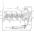
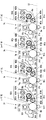
まず、図1及び2を用いて、本発明の実施形態に係るプリンタ1の概略を説明する。図1は、本発明の実施形態に係るプリンタ1の概略構成を示す断面図である。図2は、本発明の実施形態に係る各画像形成部3の拡大断面図である。そして、本実施形態にかかるプリンタ1は、図1に示すように、本体内に、シート供給部2a、搬送路2b、画像形成部3、露光装置4、中間転写部5、定着部6等が設けられる。
(Schematic configuration of image forming apparatus)
First, the outline of the
シート供給部2aは、中間転写部5等に向け、例えば、コピー用紙、OHPシート、ラベル用紙等の各種シートを収容し、モータ等の駆動機構(不図示)により回転する給紙ローラ21でシートを搬送路2bに送り出す。そして、搬送路2bは、プリンタ1内でシートを搬送し、供給されたシートを、中間転写部5、定着部6を経て排出トレイ22まで導く。搬送路2bは、搬送ローラ対23やガイド24及び搬送されるシートを中間転写部5の手前で待機させ、タイミングをあわせて送り出すレジストローラ対25等を有する。
The
そして、図1及び図2に示すように、プリンタ1は、画像データに基づき、それぞれ色の異なるトナー像を形成する部分として、4色分の画像形成部3を備える。具体的に、プリンタ1は、ブラックの画像を形成する画像形成部3a(帯電装置7a、現像装置8a、除電装置31a、清掃装置32a等を具備)と、イエローの画像を形成する画像形成部3b(帯電装置7b、現像装置8b、除電装置31b、清掃装置32b等を具備)と、シアンの画像を形成する画像形成部3c(帯電装置7c、現像装置8c、除電装置31c、清掃装置32c等を具備)と、マゼンタの画像を形成する画像形成部3d(帯電装置7d、現像装置8d、除電装置31d、清掃装置32d等を具備)と、を備える。
As shown in FIGS. 1 and 2, the
ここで、図2に基づき、各画像形成部3a〜3dを詳述する。尚、各画像形成部3a〜3dは、形成するトナー像の色が異なるだけで、いずれも基本的に同様の構成である。そこで、下の説明では、各画像形成部3内のa、b、c、dの符号は、特に説明する場合を除き省略する(尚、図2では、画像形成部3a、3b、3c、3d内の各部材に、識別的にa、b、c、dの符号を付すこととする。)
Here, based on FIG. 2, each
各感光体ドラム9は、周面にトナー像を担持し、例えば、アルミニウム製のドラムの基体の外周面上に正帯電のアモルファスシリコンの感光層を有し、駆動装置(不図示)によって所定のプロセススピードで紙面反時計方向に回転駆動される。
Each
各帯電装置7(帯電部に相当)は、帯電ローラ71を有し、感光体ドラム9を一定の電位で帯電させる。各帯電ローラ71は、各感光体ドラム9に接し、感光体ドラム9に合わせ回転する。又、各帯電ローラ71には、帯電電圧印加部72(図5参照)により直流と交流が重畳された電圧が印加され、感光体ドラム9は、所定の正極性の電位(例えば、200V〜300V、暗電位)に均一に帯電される。尚、各帯電ローラ71の表面の清掃用の清掃ブラシ73(例えば、軸に樹脂製ブラシ等を巻き付けたもの)が設けられる。又、帯電装置7は、コロナ放電や帯電ブラシ等を用いるものでも良い。
Each charging device 7 (corresponding to a charging unit) has a charging roller 71 and charges the
各現像装置8は、トナーと磁性体のキャリアを含む現像剤(いわゆる2成分現像剤)を収納する(現像装置8aはブラック、現像装置8bはイエロー、現像装置8cはシアン、現像装置8dはマゼンタの現像剤を収納)。各現像装置8は、現像ローラ81と、磁気ローラ82と、搬送部材83とを有する。各現像ローラ81は、それぞれ感光体ドラム9に対向し、所定のギャップ(例えば、1mm以下)を設けて配される。そして、各磁気ローラ82は、各現像ローラ81の右斜め上方に対向し、隙間を設けて配される。そして、各搬送部材83は、各磁気ローラ82の上方に設けられる。
Each developing
各現像ローラ81と各磁気ローラ82のローラ軸811、821は固定される。又、現像ローラ81と磁気ローラ82の内部のローラ軸811、821には、軸線方向にのびる磁石813、823が取り付けられる。そして、各現像ローラ81と各磁気ローラ82は、それぞれ磁石813、823を覆う円筒状のスリーブ812、822を有し、画像形成時、後述の調整時、このスリーブ812、822が回転する(図3参照)。又、磁石813と磁石823は、各スリーブ812、822の最接近位置で異極が向かい合う。
The
これにより、各現像ローラ81と、各磁気ローラ82間には、磁性体キャリアで磁気ブラシが形成される。磁気ブラシと磁気ローラ82のスリーブ822の回転や磁気ローラ82への電圧印加(磁気ローラバイアス印加部84:図5参照)等で、現像ローラ81に、トナーが供給され、現像ローラ81にトナーの薄層が形成される。又、現像後に残留したトナーは、磁気ブラシで現像ローラ81から引き剥がされる。各搬送部材83は、例えば、軸に対しスクリューが螺旋状に設けられ、現像剤を各現像装置8内で搬送、撹拌し、トナーを所定のレベルに帯電させる(本実施形態では、トナーは正帯電)。
Thereby, a magnetic brush is formed by the magnetic carrier between each developing
各清掃装置32は、感光体ドラム9の清掃を行い、例えば、外周部分に弾性を有する円筒状の素材の清掃部材33を有し、清掃部材33は、各感光体ドラム9に当接し、ドラム表面の転写残トナーを除去、回収する。又、各清掃装置32の下方に、感光体ドラム9に対し光を照射して除電を行う除電装置31(例えば、アレイ状のLED)が設けられる。
Each
各画像形成部3の上方の露光装置4(露光部に相当)は、入力されるカラー色分解された画像信号をレーザ出力部(不図示)にて光信号にそれぞれ変換し、変換された光信号であるレーザ光(破線で図示)を出力し、帯電後の感光体ドラム9の走査露光を行って、静電潜像を形成する。尚、露光装置4は、多数のLEDからなるもの等を用いてもよい。露光装置4は、半導体レーザ装置(レーザダイオード)、ポリゴンミラー(ポリゴンモータにより回転)、fθレンズ、ミラー等の光学系部材(不図示)を備え、レーザ光を各感光体ドラム9に照射し、画像データに併せた静電潜像を感光体ドラム9上に形成する。具体的に、本実施形態の各感光体ドラム9は正帯電し、光の照射部分は電位が下がり(例えば、ほぼ0V)、電位の低下部分に正帯電トナーが付着する(例えば、ベタ塗り画像の場合、全ライン、全画素にレーザ光を照射)
An exposure device 4 (corresponding to an exposure unit) above each
図1に戻り、中間転写部5は、感光体ドラム9からトナー像の1次転写を受けて、シートに2次転写を行い、各1次転写ローラ51a〜51d、中間転写ベルト52、駆動ローラ53、従動ローラ54、55、56、2次転写ローラ57、ベルト清掃装置58等で構成される。各1次転写ローラ51a〜51dは、無端状の中間転写ベルト52を介して各感光体ドラム9に当接し、転写用の電圧を印加する転写電圧印加部59(不図示)に接続され、トナー像を中間転写ベルト52に転写する。
Returning to FIG. 1, the
中間転写ベルト52は、駆動ローラ53、従動ローラ54、55、56に張架され、モータ等の駆動機構(不図示)に接続される駆動ローラ53の回転駆動により図1では反時計方向に周回する。又、駆動ローラ53は、中間転写ベルト52を介して2次転写ローラ57と当接し、2次転写部を形成する。シートへのトナー像転写を説明すると、各画像形成部3で形成されたトナー像(ブラック、イエロー、シアン、マゼンタの各色)は、各1次転写ローラ51への所定の電圧を印加により、順次、中間転写ベルト52に1次転写される。この時、各色のトナー像は、ずれなく重畳されるように、タイミングを取られつつ1次転写される。そして、各色重ね合わされたトナー像は、所定の電圧を印加された2次転写ローラ57により、シートに転写される。尚、2次転写後に中間転写ベルト52上に残った残トナー等は、ベルト清掃装置58で除去されて回収される(図1参照)。
The
前記定着部6は、2次転写部の転写材搬送方向の下流側に配され、シートに2次転写されたトナー像を加熱・加圧して定着させる。そして、定着部6は主として、発熱源を内蔵する定着ローラ61と、これに圧接される加圧ローラ62とで構成され、ニップが形成される。そして、トナー像の転写されたシートは、ニップを通過すると加熱・加圧され、その結果、トナー像がシートに定着する。尚、定着後のシートは、排出トレイ22に排出され画像形成処理が完了する。
The fixing
(放電検出用の構成)
次に、本発明の特徴となる各現像ローラ81への現像バイアス印加と各感光体ドラム9間の放電検出に関する構成を説明する。
(Configuration for discharge detection)
Next, the configuration relating to the application of the developing bias to each developing
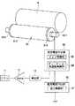
図3は、本発明の実施形態に係る現像ローラ81への現像バイアス印加と感光体ドラム9間の放電発生検出に関する現像ローラ81周辺の構成図である。ただし、図3は1つの画像形成部3についてのみ示し、画像形成部3ごとに直流電圧印加部85、交流電圧印加部86、検出部14、アンプ15が設けられ、各アンプ15の出力が、後述する制御部10のCPU11に入力される。ここで、直流電圧印加部85、交流電圧印加部86、検出部14、アンプ15のそれぞれについて、画像形成部3の区別を示すa、b、c、dの符号を付しても良いが、各画像形成部3では同様のものが設けられるので、記載の煩雑さを回避するため、以下では、a、b、c、dの符号は省略して説明する。
FIG. 3 is a configuration diagram around the developing
図3に示すように、感光体ドラム9にギャップが設けられつつ対向する現像ローラ81は、ローラ軸811、画像形成時にトナーを担持するスリーブ812、キャップ814を有する。ローラ軸811はスリーブ812を挿通され、スリーブ812の両端に円形のキャップ814が嵌入される。又、現像ローラ81のローラ軸811には、感光体ドラム9へのトナーの供給のため、直流電圧印加部85と、交流電圧印加部86が接続される。
As shown in FIG. 3, the developing
直流電圧印加部85は、現像ローラ81に印加する直流成分を発生させる回路であり、その出力は交流電圧印加部86に入力される。そして、直流電圧印加部85は、出力制御部87を有し、出力制御部87は、直流電圧印加部85が出力するバイアスの値をCPU11の指示に応じて制御する。
The DC
直流電圧印加部85は、プリンタ1内の電源装置16(図4参照)からの直流電力の供給を受け、CPU11の指示に応じ、出力制御部87の制御により、出力電圧が可変な回路である(例えば、出力電圧が異なる出力端までの経路を複数有し、画像形成時と放電検出時で、その経路の選択を変える等)。これにより、現像ローラ81に印加する交流電圧をバイアスさせることができる。
The DC
又、交流電圧印加部86は、例えば、矩形波状(パルス状)であり、直流電圧印加部85の印加する直流電圧を平均値とする交流電圧を出力する回路である。そして、交流電圧印加部86は、Vpp制御部88およびデューティ比/周波数制御部89を有する。Vpp制御部88は、交流電圧のピーク間電圧(ピークトゥピーク)をCPU11の指示に応じて制御する。また、デューティ比/周波数制御部89は、交流電圧のデューティ比及び周波数をCPU11の指示に応じて制御する。
The AC
例えば、交流電圧印加部86は、スイッチング素子等を備え、出力の正負をスイッチングにより反転させ、交流電圧を出力する。そして、デューティ比/周波数制御部89は、例えば、交流電圧印加部86の出力の正負のスイッチングのタイミングを制御して、交流電圧のデューティ比や周波数を制御することができる。又、Vpp制御部88は、現像ローラ81に印加すべき交流電圧のピーク間電圧とデューティ比とに基づき、電源装置16から入力される直流電圧の昇降圧等により、交流電圧における正側のピーク値と負側のピーク値を、CPU11の指示に応じ、可変させる。尚、交流電圧印加部86の構成や、交流電圧のピーク間電圧、デューティ比、周波数を可変させる構成は、ピーク間電圧、デューティ比、周波数を変化できればよい。
For example, the AC
そして、交流電圧印加部86内には、例えば、昇圧用トランス等による昇圧回路を出力段に備えることができ、昇圧後の直流と交流の重畳された現像バイアスが、例えば、現像ローラ81のローラ軸811に印加される。これにより、スリーブ812にも現像バイアスが印加され、スリーブ812に担持される帯電トナーが飛翔する。
In the AC
検出部14は、現像ローラ81と感光体ドラム9間での放電発生時に流れる電流を電圧信号に変換し、現像ローラ81と感光体ドラム9間での放電の発生を検出する回路であり、変換した電圧信号をアンプ15に出力する。アンプ15は、検出部14からの電圧信号を増幅しCPU11に出力する。CPU11は、アンプ15からの電圧信号をA/D変換する。このA/D変換されたアンプ15の出力から、CPU11は、放電の発生や放電の大きさ(流れた電流の大きさ)を認識することができる。
The
(プリンタ1のハードウェア構成)
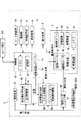
次に、図4に基づき、本発明の実施形態に係るプリンタ1のハードウェア構成を説明する。図4は、本発明の実施形態に係るプリンタ1のハードウェア構成の一例を示すブロック図である。
(Hardware configuration of printer 1)
Next, the hardware configuration of the
図4に示すように、本実施形態に係るプリンタ1は、内部に制御部10を有する。制御部10は、プリンタ1の各部を制御し、検出部14の出力が入力され放電発生を認識する。例えば、制御部10は、CPU11、記憶部12等から構成される。CPU11は、中央演算処理装置であり、記憶部12に格納され、展開される制御プログラムに基づきプリンタ1の各部の制御や演算を行う。記憶部12は、ROM、RAM、フラッシュROM等の不揮発性と揮発性の記憶装置の組み合わせで構成される。例えば、記憶部12は、プリンタ1の制御プログラム、制御データ等を記憶する。尚、本発明に関し、放電検出や現像ローラ81に印加する交流電圧の設定、調整用プログラムも記憶部12に記憶される。
As shown in FIG. 4, the
そして、制御部10は、シート供給部2a、搬送路2b、画像形成部3、露光装置4、中間転写部5、定着部6等と接続され、記憶部12の制御プログラムやデータに基づき、適切に画像形成が行われるように各部の動作を制御する。
The
又、制御部10には、印刷を行う画像データの送信元となるユーザ端末100(パーソナルコンピュータ等)等が接続され、制御部10は、受信した画像データを画像処理し、露光装置4に送信し、露光装置4はその画像データに基づき、感光体ドラム9に静電潜像を形成する。又、図4に示す、磁気ローラバイアス印加部84は、磁気ローラ82に、交流と直流を重畳した電圧を印加する回路である。又、帯電電圧印加部72は、帯電ローラ71に帯電用の電圧を印加する回路である。
The
又、本発明に関し、制御部10(CPU11)は、検出部14(アンプ15)が接続される。又、本発明の実施時、CPU11は、現像ローラ81に印加する交流電圧のピーク間電圧等を変える指示を交流電圧印加部86に与えつつ、検出部14(アンプ15)の出力から放電発生の有無の検出や、放電の大きさを判断する。そして、放電発生を検出した場合、制御部10は、その時の直流電圧や交流電圧のピーク間電圧等の値に基づき、放電発生時の現像ローラ81の感光体ドラム9の電位差の把握し、画像形成時に放電が生じないように、画像形成動作時に印加すべき現像バイアスの設定を決定する。尚、現像バイアスの設定値は記憶部12に記憶できる。
Further, with respect to the present invention, the control unit 10 (CPU 11) is connected to the detection unit 14 (amplifier 15). Further, during the implementation of the present invention, the
又、本発明に関し、各画像形成部3には、例えば、履歴データを記憶するチップ状のメモリ34(記憶部に相当)が搭載される。ここで、履歴データとは、画像形成部3の寿命管理の観点から累計印刷枚数や、印刷実行日時とその枚数や、使用時間(稼働時間)を示すデータなどを含むことができる。又、履歴データには、後述する現像ローラ81に印加する交流電圧の調整を行った日時のデータを含むこともできる。又、先の交流電圧の調整からの現在までの各画像形成部3の使用時間をデータとして記憶しても良いし、調整後に印刷された枚数に、1枚あたりに要する時間を乗じて換算(例えば、CPU11が演算)して、先の調整からの使用時間が記憶されても良い。この画像形成部3に関する使用や調整の履歴に関する履歴データは、制御部10の記憶部12に記憶しても良い。
In the present invention, each
(現像ローラ81に印加する交流電圧の初期設定)
次に、図5及び図6に基づき、現像ローラ81に印加する交流電圧の初期設定方法の一例を説明する。図5は、本発明の実施形態に係る現像ローラ81に印加する交流電圧の初期設定方法の一例を示すフローチャートである。図6は、本発明の実施形態に係る現像ローラ81に印加する交流電圧の詳細を説明するタイミングチャートである。尚、この初期設定動作は、各画像形成部3について、1つずつ順に行われ、計4回行われる。
(Initial setting of AC voltage applied to developing roller 81)
Next, an example of an initial setting method of the AC voltage applied to the developing
尚、この初期設定は、例えば、初期不良発見や初期設定として製造時や、プリンタ1の設置時、現像装置8や感光体ドラム9の交換時に行える。又、プリンタ1の設置時に行うのは、設置環境の標高によって気圧が変化し(例えば、日本国内とメキシコの高地との差)、放電が発生する電圧に差があるためである。現像装置8等の交換時に行うのは、感光体ドラム9と現像ローラ81とのギャップが交換前と変わるためである。尚、上記の例に限られず、実施タイミングは、適宜設定することは可能である。
This initial setting can be performed, for example, at the time of manufacturing as initial defect detection or initial setting, when the
まず、操作部(不図示)において所定の操作がされ、初期設定制御が開始されると(スタート)、CPU11の指示で、不図示の駆動機構により、感光体ドラム9、現像ローラ81、中間転写ベルト52等の画像形成部3と中間転写部5での各種回転体の回転が開始される(ステップS1)。この各回転体の駆動は初期設定が終了するまで継続する。
First, when a predetermined operation is performed in an operation unit (not shown) and the initial setting control is started (start), the
次に、初期設定を行うにあたり、予備的動作としての初期動作が行われる(ステップS2)。例えば、初期動作では、現像ローラ81と磁気ローラ82にそれぞれ、交流と直流の電圧が印加される。この初期動作での磁気ローラ82への電圧印加により、少量のトナーが磁気ローラ82から現像ローラ81に供給される。放電発生検出では、基本的に、現像ローラ81にトナーを担持させないが、全くトナーを担持させないと、感光体ドラム9とこれに接する回転部材(中間転写ベルト52等)との摩擦が大きくなりすぎる等、弊害が生じうるので、若干量、感光体ドラム9にトナーが供給される。
Next, when performing the initial setting, an initial operation as a preliminary operation is performed (step S2). For example, in the initial operation, AC and DC voltages are applied to the developing
次に、放電の発生を検出するための準備状態に移行する(ステップS3)、例えば、準備状態では、CPU11の指示により、帯電電圧印加部72が、帯電装置7に電圧印加を開始する。尚、初期設定動作が終了するまで、帯電装置7に印加される電圧はONとすることができる。又、現像ローラ81に印加する交流電圧のピーク間電圧が、予め定められた最初の値となるように高められる(例えば、設定可能な最低値)。
Next, the process proceeds to a preparation state for detecting the occurrence of discharge (step S3). For example, in the preparation state, the charging
放電検出状態に移行し、CPU11はアンプ15の出力電圧が所定の閾値を越えた回数をカウントする(ステップ♯4)。具体的には、制御部10は、準備状態で設定された交流電圧、又は、後述する条件変更状態で設定された交流電圧を印加させ、検出部14の出力から放電の発生を検出、認識する。又、この時、CPU11の指示により、露光装置4が露光を継続して行う(感光体ドラム9全面を露光して、表面電位をほぼゼロVまで落とし、安定させるため)。尚、本実施形態のプリンタ1では、トナーと感光体ドラム9の帯電極性が正極性であり、露光部分にトナーがのるので、継続した露光は、ベタ塗り画像の静電潜像形成と同じである。従って、放電検出状態では、例えば、制御部10から露光装置4に、ベタ塗りの画像データ(例えば、記憶部12が記憶)が送り込まれる。
In the discharge detection state, the
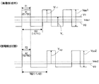
ここで、図6に基づき、放電検出状態で現像ローラ81に印加される電圧について説明しておく。画像形成時のタイミングチャートにおける矩形波は、現像ローラ81に印加される現像バイアス(交流+直流)の波形の一例である。そして、「Vdc1」は、直流電圧印加部85のバイアスの電位を示す。「V0」は、感光体ドラム9の露光装置4による露光後の電位(ほぼ0V=明電位)を示す。「V1」は、感光体ドラム9の帯電後の電位(露光しない部分の電位。例えば、200〜300V程度)を示す。「V+1」は、V0と、画像形成時の現像バイアスの正のピーク値との電位差を示す。「V-」は、V1と現像バイアスの負のピーク値との電位差を示す。「Vpp1」は、画像形成時の現像ローラ81に印加する交流電圧のピーク間電圧を示す。又、「T1」は、矩形波におけるHigh状態(正極性状態)の時間である。「T01」は、矩形波の周期を示す。
Here, the voltage applied to the developing
一方、放電検出状態のタイミングチャートにおける矩形波は、で、現像ローラ81に印加される現像バイアスの波形を示す。「Vdc2」は、検出時の直流電圧印加部85のバイアスの電位を示す。又、「V0」は、図6上段と同様、感光体ドラム9の露光装置4による露光後の電位(ほぼ0V)を示す。「V+2」は、検出時の現像バイアスの正のピーク値とV0との電位差を示す。「Vpp2」は、検出時の現像ローラ81に印加する交流電圧のピーク間電圧を示す。「T2」は、矩形波におけるHigh状態(正極性状態)の時間である。「T02」は、矩形波の周期である。
On the other hand, the rectangular wave in the timing chart of the discharge detection state indicates the waveform of the developing bias applied to the developing
まず、放電検出状態では、CPU11の指示により、出力制御部87は直流電圧印加部85の出力を、放電検出状態用の設定値Vdc2(例えば、100V〜200V)に設定する。又、CPU11の指示で、Vpp制御部88は交流電圧印加部86の出力する交流電圧のVpp2を設定する。又、CPU11の指示で、デューティ比/周波数制御部89は、交流電圧印加部86の出力する交流電圧のデューティ比D2(周期T02に対するHighの時間T2の比、T2/T02)を放電発生検出用の設定値に設定し、交流電圧印加部86の出力する交流電圧の周波数f2(=1/T02)を放電発生検出用の設定値に設定する(図6下段)。
First, in the discharge detection state, the
ここで、デューティ比D2(条件:50%未満)は、画像形成時のデューティ比D1(周期T01に対するHighの時間T1の比、T1/T01)より小さく設定される(例えば、D1=40%、D2=30%)。そして、周波数f2は、交流電圧のプラス側時間が画像形成時と放電発生検出時で同じとなるよう設定される(即ち、T1=T2。例えば、D1=40%、D2=30%の場合、画像形成時の周波数f1=4kHzであれば、f2=3kHz)。これにより、画像形成時と同じ時間だけ、正極性の電圧が現像ローラ818に印加される。 Here, the duty ratio D2 (condition: less than 50%) is set smaller than the duty ratio D1 (the ratio of the high time T1 to the period T01, T1 / T01) (for example, D1 = 40%, D2 = 30%). The frequency f2 is set so that the positive time of the AC voltage is the same when the image is formed and when the discharge is detected (ie, T1 = T2, for example, when D1 = 40% and D2 = 30%, If the frequency f1 = 4 kHz during image formation, f2 = 3 kHz). As a result, a positive voltage is applied to the developing roller 818 for the same time as the image formation.
放電検出状態で、デューティ比D2を画像形成時よりも小さくすることで、交流電圧の平均値(Vdc2)との関係で、現像ローラ81での正側のピーク値とVdc2の電位差の方が、負側よりも大きくなる。本実施形態の感光体ドラム9の感光層は、正帯電のアモルファスシリコンであり、現像ローラ81の電位が感光体ドラム9よりも低い状態では、理由は多々考えられるが、放電時に大電流が流れやすい特性があることが経験的に得られている。しかし、本実施形態の放電検出状態では、現像ローラ81の電位を感光体ドラム9よりも大きくし、放電時に大電流が流れ難くして、感光体ドラム9の損傷(例えば、放電で感光体ドラム9に微少な穴が開く等)が防がれる。
In the discharge detection state, the duty ratio D2 is made smaller than that at the time of image formation, so that the potential difference between the positive peak value at the developing
図5に戻り、説明を続ける。ステップ♯4の後、制御部10は、カウント数が0回でないかを確認し(ステップS5)、0回で無ければ(ステップS5のNo)、放電発生ありとして、ステップ♯8に移行する(詳細は後述)。尚、この時、放電発生時の交流電圧のピーク間電圧から所定の刻み幅ΔV1だけ減少させた後、ΔV1よりも小さい所定の刻み幅ΔV2だけ増加させ、放電検出状態と条件変更状態(後述のステップ♯7)を繰り返し、放電が発生するピーク間電圧をより細かく探し当ててもよい。
Returning to FIG. 5, the description will be continued. After
一方、0回であれば(ステップS5のNo)、放電発生なしとして、現状のピーク間電圧が設定可能な最大値(例えば、1500〜3000V)に達しているかをCPU11が確認し(ステップS6)、達していれば(ステップS6のYes)、ステップS8に移行する(詳細は後述)。一方、達していなければ(ステップS6のNo)、条件変更状態に移行する。この条件変更状態では、CPU11の指示で、Vpp制御部88が、交流電圧印加部86の出力する交流電圧のピーク間電圧を現状より所定の刻み幅ΔV1(例えば、30〜100Vなど)だけ増加させる設定が行われる(ステップS7)。その後、放電検出状態に戻る(ステップ♯3へ)。これにより、放電発生が認められるまで、条件変更状態と放電検出状態が繰り返され、繰り返しの間、基本的に、段階的に一定の刻み幅で現像ローラ81に印加する交流電圧のピーク間電圧が高められる。
On the other hand, if it is 0 times (No in step S5), the
次に、ステップS8について、詳述する。放電発生検出時(ステップS5のNo)や、設定可能な最大ピーク間電圧でも検出できなかった場合(ステップS6のYes)、CPU11は、最大ピーク間電圧、又は、放電が発生すると認めたピーク間電圧Vpp2、周波数f2、デューティ比D2、バイアス設定値Vdc2から、図6に示す電位差V+2(放電検出時又は設定可能な最大値でのVpp2印加時の感光体ドラム9と現像ローラ81の電位差)を求める(ステップS8)。
Next, step S8 will be described in detail. When discharge is detected (No in step S5) or when the maximum peak-to-peak voltage that can be set cannot be detected (Yes in step S6), the
ここで、V+2は容易に求めることができる。CPU11は、ピーク間電圧の大きさを指定してVpp制御部88に指示を出す。従って、制御部10は、放電発生を検出した場合、その時のVpp2を把握している。又、設定値としてのデューティ比D2と、Vdc2を基準とし、正側と負側の面積を等しくすることに基づき、Vpp2の正側のピーク値とVdc2の電位差が求められる。この電位差に、Vdc2とV0との電位差(V0は、ほぼ0Vなので、Vdc2と扱える)を加えれば、V+2が求められる(図6参照)。
Here, V +2 can be easily obtained.
具体的に、放電発生検出動作時のVpp2は、段階的に変更され、デューティ比D2、バイアス設定値Vdc2を一定とすれば、各Vpp2の大きさ応じ、予めV+2を算出しておき、ルックアップテーブルとしてデータ化し、CPU11がそのテーブルを参照し、V+2が求められても良い。尚、このテーブルは、例えば、記憶部12に記憶しておけばよい。
Specifically, Vpp2 at the time of discharge occurrence detection operation is changed in stages. If the duty ratio D2 and the bias setting value Vdc2 are constant, V + 2 is calculated in advance according to the magnitude of each Vpp2, The data may be converted into a lookup table, and the
次に、求められたV+2に基づき、CPU11は、図5に示したV+1と、V-がいずれも求められたV+2よりも、小さくなるように、画像形成時に現像ローラ81に印加する交流電圧のピーク間電圧Vpp1を設定し、制御部10は記憶部12のフラッシュROM等に不揮発的に記憶させる(ステップS9)。具体的に、Vpp1の決定方法は多様であるが。例えば、V+1とV-をV+2よりも、どれほど小さくすれば放電が発生しないか(マージンをどれほどとるべきか)は、使用トナーにより異なる等の事情から、開発時の実験に基づき、例えば、求められたV+2に対し、画像形成時に放電が発生しないと認められるVpp1の値をテーブル化し、CPU11がそのテーブルを参照し、Vpp1が定められても良い。尚、このテーブルも記憶部12に記憶しておけばよい。これにより、画像形成時、放電が発生しないできるだけ大きな交流電圧を印加できる。そして、このVpp1の設定が完了すれば、画像形成時の現像ローラ81に印加する交流電圧Vpp1の設定は終了する(エンド)。そして、プリンタ1は、制御完了後、画像形成可能な状態に復帰する。
Next, based on the obtained V +2 , the
(現像ローラ81に印加する交流電圧の調整)
次に、図7及び図8に基づき、経時変化に対応する現像ローラ81に印加する交流電圧の調整の一例を説明する。図7は、本発明の実施形態に係る現像ローラ81に印加する交流電圧の調整の制御の一例を示すフローチャートである。図8は、本発明の実施形態に係る現像ローラ81に印加する交流電圧の調整におけるタイミングチャートである。
(Adjustment of AC voltage applied to developing roller 81)
Next, an example of adjustment of the AC voltage applied to the developing
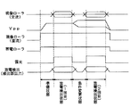
尚、図8での「現像ローラ(交流)」は、交流電圧印加部86が現像ローラ81に交流電圧を印加するタイミングを示す。「Vpp」は、現像ローラ81への交流電圧のピーク間電圧の大きさの変化を示す。「現像ローラ(直流)」は、直流電圧印加部85が現像ローラ81に直流電圧を印加するタイミングを示す。又、「帯電ローラ」は、帯電装置7が感光体ドラム9を帯電させるタイミングを示す。「露光」は、露光装置4での感光体ドラム9の露光(レーザ光照射)タイミングを示す。「放電検出(検出部14出力)」は、検出部14による放電発生検出タイミングを示す。
Note that “developing roller (AC)” in FIG. 8 indicates the timing at which the AC
ここで、経時変化と現像ローラ81に印加する交流電圧の調整の必要性を説明する。感光体ドラム9や現像ローラ81の使用で、感光体ドラム9や現像ローラ81のギャップ長が変化する場合がある。例えば、各部材(例えば、帯電ローラ71)との摩擦で、感光体ドラム9等の感光層の層厚が変化した場合や、ジャム処理やメンテナンスで感光体ドラム9等に力が加わったため、ギャップ長が微妙に変わった場合や、感光体ドラム9と現像ローラ81のギャップの維持部材(例えば、感光体ドラム9等の回転軸を支える支軸部材等)が摩耗した場合や、落下等のプリンタ1に衝撃があった場合などが考えられる。
Here, the change with time and the necessity of adjusting the AC voltage applied to the developing
そして、ギャップ長は、感光体ドラム9と現像ローラ81間で、放電が生ずる交流電圧の大きさに影響を与える。従って、ギャップ長が変化すれば、放電の生ずる交流電圧の大きさが変化する。尚、設置環境での気圧、気温、湿度等の環境や、現像ローラ81に交流電圧を印加する回路の劣化等も、放電開始電圧が変化する要因となり得る。
The gap length affects the magnitude of the AC voltage that generates a discharge between the
従って、図5や図6を用いて説明したように、初期設定として、放電が発生せず、かつ現像効率が高くなるように、現像ローラ81に印加する交流電圧を精度良く定めても、経時変化の影響により、初期設定が、将来にわたり、現像ローラ81に印加すべき交流電圧として最適であるとは限らない。従って、経年変化に対応して、画像形成時に印加すべき交流電圧を調整(キャリブレーション)する必要がある。
Therefore, as described with reference to FIGS. 5 and 6, as an initial setting, even if the AC voltage applied to the developing
そこで、制御部10が、所定のタイミングで、現像ローラ81に印加する交流電圧を変化させつつ放電の発生の有無を確認して、画像形成時に現像ローラ81に印加する交流電圧の調整の一例を説明する。尚、この調整は所定のタイミングで行われるが、そのタイミングとしては、主電源投入後の立ち上げ時、前回の放電発生検出動作から所定枚数(例えば、数十枚〜数百枚)印刷を行った時、画像形成開始時、画像形成が終了してから画像形成の指示がない状態が所定時間継続した時(例えば、スリープモードに入る直前等)のいずれか、若しくは、これらの時の複数の組み合わせを実行タイミングとして、調整を実行することができる。
Therefore, the
そして、図7のスタートは、交流電圧の調整を実行する所定のタイミングに至り、制御部10が、交流電圧の調整制御を開始した時点である(スタート)。そして、制御部10は画像形成部3や中間転写部5等の各種回転体の回転を開始させる(ステップ♯21)。
Then, the start of FIG. 7 is the time when the
次に、制御部10は、交流電圧の調整時に最初に現像ローラ81に印加すべき交流電圧を決定する(ステップ♯22)。ここで、本実施形態では、感光体ドラム9の損傷回避のため、調整時も、現像ローラ81の電位が高い状態で放電させ、放電電流が一方向でのみ流れるようにする。そこで、本実施形態では、交流電圧の調整時に最初に現像ローラ81に印加する交流電圧は、現在の画像形成時に印加する交流電圧(図6におけるVpp1)から、テーブル等やVpp1を求めた際の逆演算を例えばCPU11が行って、交流電圧の調整時用(初期設定と同様)の交流電圧Vpp2を決定する(図6参照)。
Next, the
言い換えると、制御部10の記憶部12には、現在の画像形成時に現像ローラ81に印加する交流電圧の情報が、設定データ(例えば、ピーク間電圧、直流バイアス値、デューティ比、周波数等の各パラメータ)として記憶されており、その設定データに基づき、テーブル等を参照し、調整時の放電検出において、最初に現像ローラ81に印加すべき交流電圧が決定される。例えば、上述の初期設定後では、設定データの内容は、初期設定によって決定された画像形成時に現像ローラ81に印加する交流電圧に関してのデータとなる。又、後述するように、交流電圧の調整により、画像形成時に現像ローラ81に印加すべき交流電圧の変更があれば、設定データは、変更後の交流電圧に関してのデータとなる。尚、設定データには、現在の画像形成時に現像ローラ81に印加する交流電圧の情報だけでなく、交流電圧の調整時に最初に現像ローラに印加すべき交流電圧の情報そのものが含まれていても良い。
In other words, the
そして、帯電装置7の動作開始や、交流電圧印加部86の出力電圧を、調整時に現像ローラに最初に印加する交流電圧値(設定データにより定められる)にまで高める準備状態に移行する(ステップ♯23、図8参照)。本制御での準備状態は、初期設定時の準備状態と基本的に同様である(図5参照)。その後、露光装置4が露光を継続して行う等の、放電検出状態に移行し(図8参照)、CPU11はアンプ15の出力電圧が所定の閾値を越えた回数をカウントする(ステップS24)。尚、本制御での放電検出状態は、デューティ比、直流バイアス値等、初期設定時の放電検出状態と基本的に同様である(図5、図6参照)。そして、制御部10は、カウント数が0回かを確認する(ステップS25)。
Then, the operation of the
もし、放電を検出しなければ(ステップ25のYes)、準備状態に移行し、制御部10は、最初に印加する交流電圧よりもピーク間電圧が大きい交流電圧(例えば+10〜+50V等)を現像ローラ81に印加するようにVpp制御部10に指示する(ステップS26、図8参照)。そして、放電検出状態に移行し(図8参照)、CPU11はアンプ15の出力電圧が所定の閾値を越えた回数をカウントし(ステップ♯27)、制御部10は、カウント数が0回でないかを確認する(ステップS28)。
If no discharge is detected (Yes in step 25), the process proceeds to the preparation state, and the
もし、放電を検出すれば(ステップ28のNo)、設定データに変更を加えず終了する(エンド)。一方、放電を検出しなければ(ステップ♯28のYes)、制御部10は、初期設定の場合と同様に、直前の放電検出状態での交流電圧に基づき、電位差V+2(放電検出時でのVpp2印加時の感光体ドラム9と現像ローラ81の電位差)を求め、画像形成時に現像ローラ81に印加すべき交流電圧Vpp1を決定する(ステップ♯29)。
If a discharge is detected (No in step 28), the setting data is not changed and the process ends (END). On the other hand, if the discharge is not detected (Yes in step # 28), the
もし、ステップ♯25において、放電を検出すれば(ステップS25のNo)、このままでは、画質の低下や感光体ドラム9の損傷が懸念されるので、準備状態に移行し、制御部10は、最初に印加する交流電圧よりもピーク間電圧が小さい交流電圧(例えば−10〜−50V等)を現像ローラ81に印加するようにVpp制御部10に指示する(ステップS30)。そして、放電検出状態に移行し、CPU11はアンプ15の出力電圧が所定の閾値を越えた回数をカウントし(ステップ♯31)、制御部10は、カウント数が0回でないかを確認する(ステップS32)。
If a discharge is detected in step # 25 (No in step S25), there is a concern that the image quality is deteriorated or the
もし、カウント数が0回でなく放電を検出すれば(ステップ32のYes)、まだ交流電圧が大きすぎると判断できるので、直前の放電検出状態での交流電圧よりも、更にピーク間電圧が小さい交流電圧(例えば−10〜−50V)を基準として電位差V+2(放電検出時でのVpp2印加時の感光体ドラム9と現像ローラ81の電位差)を求め、画像形成時に現像ローラ81に印加すべき交流電圧Vpp1を決定する(ステップ♯33)。
If the number of counts is not 0 and discharge is detected (Yes in step 32), it can be determined that the AC voltage is still too large, so the peak-to-peak voltage is smaller than the AC voltage in the previous discharge detection state. A potential difference V +2 (potential difference between the
一方、ステップ♯32において、カウント数が0回で、放電を検出しなければ(ステップ♯32のYes)、直前の放電検出状態での交流電圧を基準とし、画像形成時に現像ローラ81に印加すべき交流電圧Vpp1を決定する(ステップ♯29)。そして、ステップ♯29、33で決定された画像形成時に印加すべき交流電圧を、設定データとして更新・記憶する(ステップ♯34)。そして、交流電圧の調整制御は、終了する(エンド)。
On the other hand, in
まとめると、記憶部12は、調整時、現在、画像形成時に現像ローラ81に印加する交流電圧の大きさに応じ、最初に現像ローラ81に印加すべき交流電圧に関する設定データを記憶する。そして、調整時、制御部10は、設定データに基づき、交流電圧印加部86に現像ローラ81に交流電圧を印加させ、放電の発生を認識した場合、制御部10は、画像形成時に現像ローラ81に印加する交流電圧を小さくさせるとともに、設定データを更新し、放電の発生の認識しない場合、制御部10は、画像形成時に現像ローラ81に印加する交流電圧を大きく又は現状維持させるとともに、画像形成時の交流電圧を大きくする場合のみ設定データを更新する。
In summary, the
(交流電圧の調整を行う画像形成部3の順番決定)
次に、図9に基づき、本実施形態の交流電圧の調整を行う画像形成部3の順番決定の一例を説明する。図9は、本実施形態の交流電圧の調整を行う画像形成部3の順番決定の一例を示すフローチャートである。
(Determining the order of the
Next, an example of determining the order of the
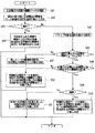
本実施形態のプリンタ1では、現像ローラ81に印加する交流電圧の調整を行うが、1回の交流電圧の調整では、1つの画像形成部3に対してのみ交流電圧の調整を行う。これにより、1回の交流電圧の調整に要する時間は、全ての画像形成部3に対して調整を行う場合に比べ、調整動作に要する時間は、はるかに短くなる(1/4)。これにより、交流電圧の調整が終了するまで、使用者を長時間待たせることがない。
In the
そこで、現像ローラ81に印加する交流電圧の調整を行う画像形成部3の順番、選択が問題となるので、本実施形態のプリンタ1での画像形成部3の順番、選択の決定における制御を図9に基づき説明する。
Therefore, since the order and selection of the
まず、図9におけるスタートは、交流電圧の調整のタイミングに至って直後の状態である。次に、制御部10は、交流電圧の調整の履歴データ(上述したように、記憶部12やメモリ34に記憶されている)を確認し(ステップ♯41)、制御部10は履歴データを確認しつつ、現在の周で既に交流電圧の調整を行った画像形成部3を選択対象から除外し(ステップ♯42)、制御部10は、現在の交流電圧調整か1周目であるかを確認する(ステップ♯43)。ここで、画像形成部3の総数分の交流電圧の調整回数分で1周が構成される(本例では4回で1周)である。又、1周につき、基本的に、各画像形成部3に対し1回ずつ現像ローラ81に印加する交流電圧の調整が実行される(周単位)。
First, the start in FIG. 9 is a state immediately after the timing of adjusting the AC voltage. Next, the
もし、1週目であれば(ステップ♯43のYes)、制御部10は、履歴データを確認しつつ、予め定められた順番(例えば、ブラック→シアン→マゼンタ→イエロー)に基づき、未だ交流電圧の調整を行っておらず、順番が上位の色の画像形成部3について、交流電圧の調整を実行する画像形成部3を決定する(ステップ♯44)。
If it is the first week (Yes in step # 43), the
一方、1週目でなければ(2週目以降であれば)(ステップ♯43のNo)、スキップ対象を選択対象から除外する(ステップ♯45)。ここで、本実施形態のプリンタ1では、過去の交流電圧の調整において、n回(所定回数に相当)、画像形成時に現像ローラ81に印加する交流電圧に変更が無かった場合、以後も画像形成時に現像ローラ81に印加する交流電圧に変更はないと予測できるので、m周のあいだにわたり、交流電圧の調整をとばす(スキップする)設定がなされている(n及びmは任意の整数)。即ち、2周目以降の調整時、制御部10は、所定回数にわたって、調整を行っても画像形成時に印加する交流電圧の変更のない画像形成部3の調整を1又は複数周とばす。従って、スキップ対象とは、現在の周では交流電圧の調整がとばされる画像形成部3である。尚、n及びmは、任意に設定できるが、例えば、n=3ならばm=1のように設定でき、スキップが完了すれば、その画像形成部3については、nはリセットされる。
On the other hand, if it is not the first week (if it is after the second week) (No in step # 43), the skip target is excluded from the selection target (step # 45). Here, in the
このように、交流電圧の調整の選択対象を絞り込んだ上で、次に、制御部10は、選択対象となる画像形成部3が2つ以上存在するか確認する(ステップ♯46)。もし存在しなければ(ステップ♯46のNo)、残った1つの画像形成部3を、交流電圧の調整を行う対象に決定する(ステップ♯47)。一方、選択対象となる画像形成部3が2つ以上存在すれば(ステップ♯46のNo)、制御部10は、履歴データを確認しつつ、前周で交流電圧の変更のあった画像形成部3が存在するかを確認する(ステップ♯48)。即ち、2周目以降の調整時、前周の調整で画像形成時に現像ローラ81に印加する交流電圧の大きさの変更があった場合、制御部10は、画像形成時に印加する交流電圧の変更があった画像形成部3から、調整を行うのである。
In this way, after narrowing down the selection targets for the adjustment of the AC voltage, the
もし、存在すれば(ステップ♯48のYes)、前周で交流電圧の変更のあった画像形成部3が複数存在するかを確認する(ステップ♯49)。もし、複数存在すれば(ステップ♯49のYes)、制御部10は、履歴データを確認して、前周で交流電圧の調整動作の対象となってから、現在までの使用時間が長い方の画像形成部3を交流電圧の調整を行う対象に決定する(ステップ♯50)。即ち、記憶部12等に記憶され、各画像形成部3を使用履歴を示す履歴データを参照して、2周目以降の調整時、制御部10は、履歴データに基づき、前周での調整から現在までの使用時間の長い画像形成部3から、調整を行う。もし、複数存在しなければ(ステップ♯49のNo)、前周で交流電圧の変更のあった、その画像形成部3を交流電圧の調整を行う対象に決定する(ステップ♯51)。
If present (Yes in step # 48), it is confirmed whether or not there are a plurality of
ステップ♯48で、前周で交流電圧の変更のあった画像形成部3が存在しなければ(ステップ♯48のNo)、制御部10は、履歴データを確認して、前周で交流電圧の調整動作の対象となってから、現在までの使用時間が長い方の画像形成部3を交流電圧の調整を行う対象に決定する(ステップ♯52)
In
調整の順番決定では、制御部10は、画像形成部3の総数を1周分の回数とし、1周分の回数の間に、各画像形成部3に対し1回ずつ調整が実行されるように、調整を行う画像形成部3の順番を決定し、かつ、1周内での調整を行う画像形成部3の順番を固定しない。
In the adjustment order determination, the
このようにして、本実施形態によれば、1回の調整では、1つの画像形成部3に対してのみ調整を行うので、全色の画像形成部3に対して調整を行う場合に比べ、迅速に調整が終了する。従って、使用者の利便性や画像形成装置の生産性を大きく損なうことがない。又、経時変化では、現像ローラ81に印加する最適な交流電圧が変化しても劇的な変化は通常なく、1回の調整で1つの画像形成部3に対してのみ調整を行うとしても、十分に、現像効率は、高い状態で維持され、濃度が維持された高画質の画像形成装置(例えば、プリンタ1)が提供される。又、1周分の回数の間に、各画像形成部3に対し1回ずつ調整が実行されるので、全ての画像形成部3は、万遍なく調整の対象となる。又、1周分の間での調整を行う画像形成部3の順番を固定しないので、例えば、使用頻度の高い画像形成部3等の各種事情を考慮して、調整を行う画像形成部3の順番を決定することができる。
In this way, according to the present embodiment, only one
又、画像形成時に現像ローラ81に印加すべき交流電圧を、放電が生じず、かつ、現像効率が高い状態で維持でき、濃度等の変動が少なく、形成される画像の品質画像形成装置を提供することができる。又、履歴データに基づき、前周での調整時から現在までの使用時間の長い画像形成部3から、調整を行うので、前回の調整からの使用時間が長く(例えば、白黒画像を頻繁に印刷する場合など)、経時変化の影響が大きく現れやすい画像形成部3に対し優先的に調整を行うことができる。言い換えると、経時変化の影響が現れ難く、あまり使用されない画像形成部3を後回しにすることができる。従って、画像形成時に印加する交流電圧について、効率よく経時変化に対する調整を行うができ、画像形成装置の状況に応じた交流電圧の設定を行うことができる。
In addition, an AC voltage to be applied to the developing
又、制御部10は、画像形成時に印加する交流電圧の変更があった画像形成部3から調整を行うので、前回の交流電圧の調整(変更)が正しいか、早い段階で確認することができる。従って、もし、前回の交流電圧の調整が誤りであれば速やかに再調整されることになる。又、所定回数にわたって、調整後に、画像形成時に印加する交流電圧の変更がない場合、調整の必要性が少なく、しばらく調整を行わなくても画質の劣化が現れ難いと予測できるので、その色の調整を1又は複数周とばし、例えば、使用頻度が高い画像形成部3等、調整の必要性が高い画像形成部3での調整の頻度を増やすことができる。又、主電源投入後の立ち上げ時、前回の調整から所定枚数印刷を行った時、画像形成開始時、画像形成が終了してから画像形成の指示がない状態が所定時間継続した時など、大きな経時変化が生じうる場合や、使用者が使用していない、或いは、できない状態に、調整を行うので、使用者の利便性、画像形成装置の生産性の低下がない。
Further, since the
次に、他の実施形態を説明する。上記の実施形態では、放電電流の流れる方向によっては大電流となり、損傷が生じるという感光体ドラム9の特性から、交流電圧の調整時(及び初期設定時)と、画像形成時では、現像ローラ81に印加する交流電圧の大きさは、同じではない場合を例に挙げて説明した。しかし、画像形成時に印加する交流電圧を初期設定値として、調整時にも印加し、放電が生ずるか検出し、その検出の有無によって、交流電圧の調整を行っても良い。この場合、テーブル等を用いた変換作業は不要にできる。
Next, another embodiment will be described. In the above-described embodiment, the developing
又、上記の実施形態では、正帯電の感光体ドラム9やトナーを例に挙げて説明したが、本発明は負帯電の感光体ドラム9やトナーを用いた場合にも適用することができる。又、上記の実施形態では、交流電圧の調整を行う画像形成部3の順番決定では、使用時間の長さと、前周での交流電圧の変更の両方を基準とする場合を示したが、その優先順位は適宜設定できる(上記の実施形態では、前周での交流電圧の変更のあった画像形成時に対し優先的に交流電圧の調整が実施される)。いずれか一方のみを基準としても良い。又、調整タイミングの到達ごとに、調整を行う画像形成部3を決定する例を示したが、一周分が完了した時、次の周での交流電圧の調整の順番を決定してしまっても良い。
In the above embodiment, the positively charged
以上、本発明の実施形態について説明したが、本発明の範囲はこれに限定されるものではなく、発明の主旨を逸脱しない範囲で種々の変更を加えて実施することができる。 The embodiment of the present invention has been described above, but the scope of the present invention is not limited to this, and various modifications can be made without departing from the spirit of the invention.
本発明は、感光体ドラムと現像ローラを有し、現像ローラに交流電圧を印加する画像形成装置に利用可能である。 The present invention is applicable to an image forming apparatus that includes a photosensitive drum and a developing roller and applies an AC voltage to the developing roller.
1 プリンタ(画像形成装置) 3(3a、3b、3c、3d) 画像形成部
34 メモリ(記憶部の一種)
81(81a、81b、81c、81d) 現像ローラ
86 交流電圧印加部 9(9a、9b、9c、9d) 感光体ドラム
10 制御部 12 記憶部
14 検出部
DESCRIPTION OF
81 (81a, 81b, 81c, 81d) Developing
Claims (5)
データを記憶する記憶部と、
前記現像ローラと前記感光体ドラム間での放電発生を検出する検出部と、
装置の各部を制御するとともに、前記検出部の出力が入力され放電発生を認識する制御部と、を有し、
前記交流電圧印加部及び前記検出部は前記画像形成部ごとに設けられ、
各前記画像形成部の使用履歴を示す履歴データが、前記記憶部に記憶され、
前記制御部は、前記現像ローラに印加する交流電圧を変化させつつ放電の発生の有無を確認して画像形成時に前記現像ローラに印加すべき交流電圧を決定する調整を所定のタイミングで実行し、
1回の前記調整では、1つの前記画像形成部に対してのみ前記調整を行うように制御し、調整を行う前記画像形成部の順番の1周分の回数を前記画像形成部の総数とし、前記1周分の回数の間に各画像形成部に対し1回ずつ前記調整が実行されるように、前記調整を行う前記画像形成部の順番を決定し、かつ、前記1周内での前記調整を行う前記画像形成部の順番を固定せず、2周目以降の前記調整時、前記履歴データに基づき、前周での前記調整から現在までの使用時間の長い前記画像形成部から、前記調整を行うことを特徴とする画像形成装置。 An AC voltage application unit for carrying a toner image on a peripheral surface of the photoconductive drum, facing the photoconductive drum with a gap provided therebetween, carrying the toner during image formation, and supplying the toner to the photoconductive drum A plurality of image forming units that form toner images of different colors, respectively,
A storage unit for storing data;
A detector for detecting the occurrence of discharge between the developing roller and the photosensitive drum;
A control unit that controls each part of the device and recognizes the occurrence of discharge when the output of the detection unit is input;
The AC voltage application unit and the detection unit are provided for each of the image forming units,
History data indicating usage history of each of the image forming units is stored in the storage unit,
The control unit performs adjustment for determining an AC voltage to be applied to the developing roller at the time of image formation by changing the AC voltage applied to the developing roller and confirming the occurrence of discharge at a predetermined timing,
In one adjustment, control is performed so that the adjustment is performed only on one image forming unit, and the number of one turn in the order of the image forming units to be adjusted is the total number of the image forming units. The order of the image forming units to perform the adjustment is determined so that the adjustment is performed once for each image forming unit during the number of times of the one round, and the order within the one cycle is determined. The order of the image forming units to be adjusted is not fixed.At the time of the second and subsequent adjustments, based on the history data, the image forming unit having a long use time from the previous adjustment to the present time, An image forming apparatus that performs adjustment.
前記調整時、
前記制御部は、前記設定データに基づき、前記交流電圧印加部に前記現像ローラに交流電圧を印加させ、
放電の発生を認識した場合、前記制御部は、画像形成時に前記現像ローラに印加する交流電圧を小さくさせるとともに、前記設定データを更新し、
放電の発生の認識しない場合、前記制御部は、画像形成時に前記現像ローラに印加する交流電圧を大きく又は現状維持させるとともに、画像形成時の交流電圧を大きくする場合のみ前記設定データを更新することを特徴とする請求項1記載の画像形成装置。 The storage unit stores setting data relating to an AC voltage to be first applied to the developing roller according to the magnitude of the AC voltage applied to the developing roller at the time of the adjustment and at the time of image formation.
During the adjustment,
The control unit causes the AC voltage application unit to apply an AC voltage to the developing roller based on the setting data,
When recognizing the occurrence of discharge, the control unit reduces the AC voltage applied to the developing roller during image formation and updates the setting data.
When the occurrence of discharge is not recognized, the control unit increases or maintains the AC voltage applied to the developing roller during image formation, and updates the setting data only when increasing the AC voltage during image formation. The image forming apparatus according to claim 1 .
データを記憶する記憶部と、
前記現像ローラと前記感光体ドラム間での放電発生を検出する検出部と、
装置の各部を制御するとともに、前記検出部の出力が入力され放電発生を認識する制御部と、を有し、
前記交流電圧印加部及び前記検出部は前記画像形成部ごとに設けられ、
前記記憶部には、前記調整時、現在、画像形成時に前記現像ローラに印加する交流電圧の大きさに応じ、最初に前記現像ローラに印加すべき交流電圧に関する設定データが記憶され、
前記制御部は、前記現像ローラに印加する交流電圧を変化させつつ放電の発生の有無を確認して画像形成時に前記現像ローラに印加すべき交流電圧を決定する調整を所定のタイミングで実行し、1回の前記調整では、1つの前記画像形成部に対してのみ前記調整を行うように制御し、調整を行う前記画像形成部の順番の1周分の回数を前記画像形成部の総数とし、前記1周分の回数の間に各画像形成部に対し1回ずつ前記調整が実行されるように、前記調整を行う前記画像形成部の順番を決定し、かつ、前記1周内での前記調整を行う前記画像形成部の順番を固定せず、前記調整時、前記設定データに基づき、前記交流電圧印加部に前記現像ローラに交流電圧を印加させ、放電の発生を認識した場合、前記制御部は、画像形成時に前記現像ローラに印加する交流電圧を小さくさせるとともに、前記設定データを更新し、放電の発生の認識しない場合、前記制御部は、画像形成時に前記現像ローラに印加する交流電圧を大きく又は現状維持させるとともに、画像形成時の交流電圧を大きくする場合のみ前記設定データを更新し、2周目以降の前記調整時、前周の前記調整で画像形成時に前記現像ローラに印加する交流電圧の大きさの変更があった場合、前記制御部は、画像形成時に印加する交流電圧の変更があった前記画像形成部から、前記調整を行うことを特徴とする画像形成装置。 An AC voltage application unit for carrying a toner image on a peripheral surface of the photoconductive drum, facing the photoconductive drum with a gap provided therebetween, carrying the toner during image formation, and supplying the toner to the photoconductive drum A plurality of image forming units that form toner images of different colors, respectively,
A storage unit for storing data;
A detector for detecting the occurrence of discharge between the developing roller and the photosensitive drum;
A control unit that controls each part of the device and recognizes the occurrence of discharge when the output of the detection unit is input;
The AC voltage application unit and the detection unit are provided for each of the image forming units,
The storage unit stores setting data relating to an AC voltage to be first applied to the developing roller according to the magnitude of the AC voltage applied to the developing roller at the time of the adjustment and at the time of image formation.
The control unit performs adjustment for determining an AC voltage to be applied to the developing roller at the time of image formation by changing the AC voltage applied to the developing roller and confirming the occurrence of discharge at a predetermined timing, In one adjustment, control is performed so that the adjustment is performed only on one image forming unit, and the number of one turn in the order of the image forming units to be adjusted is the total number of the image forming units. The order of the image forming units to perform the adjustment is determined so that the adjustment is performed once for each image forming unit during the number of times of the one round, and the order within the one cycle is determined. The order of the image forming units to be adjusted is not fixed, and when the adjustment is performed, the AC voltage application unit applies an AC voltage to the developing roller based on the setting data, and the occurrence of discharge is recognized. The development roller In the case where the setting data is updated and the occurrence of discharge is not recognized, the control unit increases or maintains the AC voltage applied to the developing roller at the time of image formation. The setting data is updated only when the AC voltage at the time of image formation is increased , and the magnitude of the AC voltage applied to the developing roller at the time of image formation is changed by the adjustment at the previous circumference during the adjustment after the second round. If there is, the control unit performs the adjustment from the image forming unit in which the AC voltage applied at the time of image formation is changed.
データを記憶する記憶部と、
前記現像ローラと前記感光体ドラム間での放電発生を検出する検出部と、
装置の各部を制御するとともに、前記検出部の出力が入力され放電発生を認識する制御部と、を有し、
前記交流電圧印加部及び前記検出部は前記画像形成部ごとに設けられ、
前記記憶部には、前記調整時、現在、画像形成時に前記現像ローラに印加する交流電圧の大きさに応じ、最初に前記現像ローラに印加すべき交流電圧に関する設定データが記憶され、
前記制御部は、前記現像ローラに印加する交流電圧を変化させつつ放電の発生の有無を確認して画像形成時に前記現像ローラに印加すべき交流電圧を決定する調整を所定のタイミングで実行し、1回の前記調整では、1つの前記画像形成部に対してのみ前記調整を行うように制御し、調整を行う前記画像形成部の順番の1周分の回数を前記画像形成部の総数とし、前記1周分の回数の間に各画像形成部に対し1回ずつ前記調整が実行されるように、前記調整を行う前記画像形成部の順番を決定し、かつ、前記1周内での前記調整を行う前記画像形成部の順番を固定せず、前記調整時、前記設定データに基づき、前記交流電圧印加部に前記現像ローラに交流電圧を印加させ、放電の発生を認識した場合、前記制御部は、画像形成時に前記現像ローラに印加する交流電圧を小さくさせるとともに、前記設定データを更新し、放電の発生の認識しない場合、前記制御部は、画像形成時に前記現像ローラに印加する交流電圧を大きく又は現状維持させるとともに、画像形成時の交流電圧を大きくする場合のみ前記設定データを更新し、2周目以降の前記調整時、前記制御部は、所定回数にわたって、前記調整を行っても画像形成時に印加する交流電圧の変更のない前記画像形成部の前記調整を1又は複数周とばすことを特徴とする画像形成装置。 An AC voltage application unit for carrying a toner image on a peripheral surface of the photoconductive drum, facing the photoconductive drum with a gap provided therebetween, carrying the toner during image formation, and supplying the toner to the photoconductive drum A plurality of image forming units that form toner images of different colors, respectively,
A storage unit for storing data;
A detector for detecting the occurrence of discharge between the developing roller and the photosensitive drum;
A control unit that controls each part of the device and recognizes the occurrence of discharge when the output of the detection unit is input;
The AC voltage application unit and the detection unit are provided for each of the image forming units,
The storage unit stores setting data relating to an AC voltage to be first applied to the developing roller according to the magnitude of the AC voltage applied to the developing roller at the time of the adjustment and at the time of image formation.
The control unit performs adjustment for determining an AC voltage to be applied to the developing roller at the time of image formation by changing the AC voltage applied to the developing roller and confirming the occurrence of discharge at a predetermined timing, In one adjustment, control is performed so that the adjustment is performed only on one image forming unit, and the number of one turn in the order of the image forming units to be adjusted is the total number of the image forming units. The order of the image forming units to perform the adjustment is determined so that the adjustment is performed once for each image forming unit during the number of times of the one round, and the order within the one cycle is determined. The order of the image forming units to be adjusted is not fixed, and when the adjustment is performed, the AC voltage application unit applies an AC voltage to the developing roller based on the setting data, and the occurrence of discharge is recognized. The development roller In the case where the setting data is updated and the occurrence of discharge is not recognized, the control unit increases or maintains the AC voltage applied to the developing roller at the time of image formation. The setting data is updated only when the AC voltage at the time of image formation is increased, and at the time of the second and subsequent adjustments, the control unit determines the AC voltage applied at the time of image formation even if the adjustment is performed a predetermined number of times. An image forming apparatus characterized in that the adjustment of the image forming section without change is skipped over one or more rounds.
Priority Applications (1)
| Application Number | Priority Date | Filing Date | Title |
|---|---|---|---|
| JP2008218799A JP5452000B2 (en) | 2008-08-27 | 2008-08-27 | Image forming apparatus |
Applications Claiming Priority (1)
| Application Number | Priority Date | Filing Date | Title |
|---|---|---|---|
| JP2008218799A JP5452000B2 (en) | 2008-08-27 | 2008-08-27 | Image forming apparatus |
Publications (2)
| Publication Number | Publication Date |
|---|---|
| JP2010054745A JP2010054745A (en) | 2010-03-11 |
| JP5452000B2 true JP5452000B2 (en) | 2014-03-26 |
Family
ID=42070748
Family Applications (1)
| Application Number | Title | Priority Date | Filing Date |
|---|---|---|---|
| JP2008218799A Expired - Fee Related JP5452000B2 (en) | 2008-08-27 | 2008-08-27 | Image forming apparatus |
Country Status (1)
| Country | Link |
|---|---|
| JP (1) | JP5452000B2 (en) |
Families Citing this family (1)
| Publication number | Priority date | Publication date | Assignee | Title |
|---|---|---|---|---|
| JP6394994B2 (en) * | 2015-12-04 | 2018-09-26 | 京セラドキュメントソリューションズ株式会社 | Image forming apparatus |
Family Cites Families (4)
| Publication number | Priority date | Publication date | Assignee | Title |
|---|---|---|---|---|
| JP2003167394A (en) * | 2001-11-29 | 2003-06-13 | Canon Inc | Image forming apparatus |
| JP4333288B2 (en) * | 2003-09-03 | 2009-09-16 | コニカミノルタビジネステクノロジーズ株式会社 | Image forming apparatus |
| JP2005249990A (en) * | 2004-03-03 | 2005-09-15 | Seiko Epson Corp | Image forming apparatus and method for forming image |
| JP2007279277A (en) * | 2006-04-05 | 2007-10-25 | Seiko Epson Corp | Image forming apparatus and image forming method |
-
2008
- 2008-08-27 JP JP2008218799A patent/JP5452000B2/en not_active Expired - Fee Related
Also Published As
| Publication number | Publication date |
|---|---|
| JP2010054745A (en) | 2010-03-11 |
Similar Documents
| Publication | Publication Date | Title |
|---|---|---|
| JP5264436B2 (en) | Image forming apparatus | |
| US7979011B2 (en) | Image forming apparatus having a photoconductive drum | |
| US7844200B2 (en) | Image forming apparatus with a pre-exposure light control feature | |
| JP5175687B2 (en) | Image forming apparatus | |
| JP5919176B2 (en) | Developing device and image forming apparatus | |
| US10656580B2 (en) | Image forming apparatus controlling charging bias and transfer bias | |
| JP5812538B2 (en) | Developing device and image forming apparatus | |
| JP5611267B2 (en) | Developing device and image forming apparatus | |
| JP5193749B2 (en) | Image forming apparatus | |
| JP5452000B2 (en) | Image forming apparatus | |
| US9037019B2 (en) | Developing device, image forming apparatus, and method for controlling developing device | |
| US11048192B1 (en) | Image forming apparatus capable of suppressing occurrence of image defects in response to difference in carrier resistance and obtaining high image quality | |
| JP5193748B2 (en) | Image forming apparatus | |
| JP5081769B2 (en) | Image forming apparatus | |
| JP5081768B2 (en) | Image forming apparatus | |
| JP5396069B2 (en) | Image forming apparatus | |
| JP2010151981A (en) | Image forming apparatus | |
| JP5193747B2 (en) | Image forming apparatus | |
| JP5255952B2 (en) | Image forming apparatus | |
| US11500311B2 (en) | Image forming apparatus including techniques and mechanisms to suppress occurrence of an image defect caused by a transfer step | |
| JP6159694B2 (en) | Image forming apparatus | |
| JP2010224071A (en) | Image forming apparatus | |
| JP7188014B2 (en) | IMAGE FORMING APPARATUS AND IMAGE FORMING APPARATUS CONTROL PROGRAM | |
| JP5337466B2 (en) | Power supply device and image forming apparatus provided with the same | |
| JP6724555B2 (en) | Image forming device |
Legal Events
| Date | Code | Title | Description |
|---|---|---|---|
| A621 | Written request for application examination |
Free format text: JAPANESE INTERMEDIATE CODE: A621 Effective date: 20110222 |
|
| A131 | Notification of reasons for refusal |
Free format text: JAPANESE INTERMEDIATE CODE: A131 Effective date: 20120807 |
|
| A977 | Report on retrieval |
Free format text: JAPANESE INTERMEDIATE CODE: A971007 Effective date: 20120808 |
|
| A521 | Request for written amendment filed |
Free format text: JAPANESE INTERMEDIATE CODE: A523 Effective date: 20121004 |
|
| A131 | Notification of reasons for refusal |
Free format text: JAPANESE INTERMEDIATE CODE: A131 Effective date: 20130416 |
|
| A521 | Request for written amendment filed |
Free format text: JAPANESE INTERMEDIATE CODE: A523 Effective date: 20130614 |
|
| TRDD | Decision of grant or rejection written | ||
| A01 | Written decision to grant a patent or to grant a registration (utility model) |
Free format text: JAPANESE INTERMEDIATE CODE: A01 Effective date: 20131203 |
|
| A61 | First payment of annual fees (during grant procedure) |
Free format text: JAPANESE INTERMEDIATE CODE: A61 Effective date: 20131227 |
|
| R150 | Certificate of patent or registration of utility model |
Free format text: JAPANESE INTERMEDIATE CODE: R150 |
|
| LAPS | Cancellation because of no payment of annual fees |