JP5451704B2 - Image processing apparatus, image processing method, program, and image processing system - Google Patents
Image processing apparatus, image processing method, program, and image processing system Download PDFInfo
- Publication number
- JP5451704B2 JP5451704B2 JP2011201820A JP2011201820A JP5451704B2 JP 5451704 B2 JP5451704 B2 JP 5451704B2 JP 2011201820 A JP2011201820 A JP 2011201820A JP 2011201820 A JP2011201820 A JP 2011201820A JP 5451704 B2 JP5451704 B2 JP 5451704B2
- Authority
- JP
- Japan
- Prior art keywords
- image
- imaging
- recovery
- image processing
- imaging system
- Prior art date
- Legal status (The legal status is an assumption and is not a legal conclusion. Google has not performed a legal analysis and makes no representation as to the accuracy of the status listed.)
- Expired - Fee Related
Links
- 238000012545 processing Methods 0.000 title claims description 139
- 238000003672 processing method Methods 0.000 title claims description 11
- 238000011084 recovery Methods 0.000 claims description 172
- 238000003384 imaging method Methods 0.000 claims description 165
- 230000003287 optical effect Effects 0.000 claims description 84
- 238000012546 transfer Methods 0.000 claims description 44
- 230000004075 alteration Effects 0.000 claims description 37
- 238000003860 storage Methods 0.000 claims description 13
- 230000010365 information processing Effects 0.000 claims description 5
- 230000006870 function Effects 0.000 description 47
- 238000004519 manufacturing process Methods 0.000 description 42
- 238000000034 method Methods 0.000 description 33
- 238000011156 evaluation Methods 0.000 description 10
- 230000008569 process Effects 0.000 description 8
- 230000006866 deterioration Effects 0.000 description 7
- 230000009467 reduction Effects 0.000 description 7
- 238000006731 degradation reaction Methods 0.000 description 6
- 230000015556 catabolic process Effects 0.000 description 5
- 238000012937 correction Methods 0.000 description 5
- 238000004891 communication Methods 0.000 description 4
- 238000013461 design Methods 0.000 description 3
- 238000010586 diagram Methods 0.000 description 3
- 230000000694 effects Effects 0.000 description 3
- 230000006872 improvement Effects 0.000 description 3
- 206010010071 Coma Diseases 0.000 description 2
- 230000002411 adverse Effects 0.000 description 2
- 230000003321 amplification Effects 0.000 description 2
- 230000008859 change Effects 0.000 description 2
- 238000003199 nucleic acid amplification method Methods 0.000 description 2
- 230000003595 spectral effect Effects 0.000 description 2
- 241000255969 Pieris brassicae Species 0.000 description 1
- 230000003044 adaptive effect Effects 0.000 description 1
- 238000003705 background correction Methods 0.000 description 1
- 230000006835 compression Effects 0.000 description 1
- 238000007906 compression Methods 0.000 description 1
- 238000010276 construction Methods 0.000 description 1
- 238000007796 conventional method Methods 0.000 description 1
- 238000009826 distribution Methods 0.000 description 1
- 230000010354 integration Effects 0.000 description 1
- 230000001678 irradiating effect Effects 0.000 description 1
- 239000004973 liquid crystal related substance Substances 0.000 description 1
- 238000005070 sampling Methods 0.000 description 1
- 238000000926 separation method Methods 0.000 description 1
- 230000006641 stabilisation Effects 0.000 description 1
- 238000011105 stabilization Methods 0.000 description 1
- 230000008685 targeting Effects 0.000 description 1
- 238000013519 translation Methods 0.000 description 1
Images


Classifications
-
- G06T5/80—
-
- H—ELECTRICITY
- H04—ELECTRIC COMMUNICATION TECHNIQUE
- H04N—PICTORIAL COMMUNICATION, e.g. TELEVISION
- H04N1/00—Scanning, transmission or reproduction of documents or the like, e.g. facsimile transmission; Details thereof
- H04N1/40—Picture signal circuits
- H04N1/409—Edge or detail enhancement; Noise or error suppression
- H04N1/4092—Edge or detail enhancement
-
- H—ELECTRICITY
- H04—ELECTRIC COMMUNICATION TECHNIQUE
- H04N—PICTORIAL COMMUNICATION, e.g. TELEVISION
- H04N23/00—Cameras or camera modules comprising electronic image sensors; Control thereof
- H04N23/80—Camera processing pipelines; Components thereof
- H04N23/81—Camera processing pipelines; Components thereof for suppressing or minimising disturbance in the image signal generation
Landscapes
- Engineering & Computer Science (AREA)
- Multimedia (AREA)
- Signal Processing (AREA)
- Image Processing (AREA)
- Studio Devices (AREA)
- Facsimile Image Signal Circuits (AREA)
Description
本発明は、画像回復処理を用いて撮影画像の補正を行う画像処理装置、画像処理方法、プログラム、および画像処理システムに関するものである。 The present invention relates to an image processing apparatus, an image processing method, a program, and an image processing system that correct a captured image using image restoration processing.
情報のデジタル化に伴い、画像を信号値として扱えることで撮影画像に対する様々な補正処理方法が提案されている。デジタルカメラで被写体を撮像して画像化するとき、得られた画像は撮像光学系の収差によって少なからず劣化している。従来、光学系の収差によるぼけ画像を、光学伝達関数(OTF)の情報を用いてデジタル処理により補正する方法が知られている。この方法は画像回復や画像復元という言葉で呼ばれており、以降この撮像光学系の光学伝達関数の情報を用いて画像の劣化を補正する処理を回復処理と記すことにする。 Along with the digitization of information, various correction processing methods have been proposed for captured images by handling images as signal values. When a subject is imaged with a digital camera and imaged, the obtained image is deteriorated to some extent due to the aberration of the imaging optical system. Conventionally, a method for correcting a blurred image due to aberration of an optical system by digital processing using information of an optical transfer function (OTF) is known. This method is called “image restoration” or “image restoration”. Hereinafter, processing for correcting image degradation using information on the optical transfer function of the imaging optical system will be referred to as recovery processing.
また、実際の製造現場においては、レンズの製造誤差、レンズを保持する鏡筒の製造誤差等により光学系の性能にはばらつきが生じており、従来は、この製造ばらつきの影響を低減するために光学系の一部や撮像素子を偏心させていた。しかしながら、偏心調整をしたとしても、製造ばらつきの影響が無くなることは無い。このため、実際に撮影された状態で発生している収差特性と回復処理で想定している収差特性に相違が生じ、回復画像にアーティファクトとしてリンギング等の弊害が発生することがある。このように製造ばらつきは回復画像に弊害を与える懸念がある。 Also, in actual manufacturing sites, there are variations in the performance of the optical system due to manufacturing errors of the lens, manufacturing errors of the lens barrel that holds the lens, etc. In the past, in order to reduce the effects of this manufacturing variation A part of the optical system and the image sensor are decentered. However, even if the eccentricity adjustment is performed, the influence of manufacturing variation is not lost. For this reason, there is a difference between the aberration characteristic that is actually captured and the aberration characteristic that is assumed in the recovery process, and the recovery image may have an adverse effect such as ringing as an artifact. Thus, there is a concern that the manufacturing variation adversely affects the recovered image.
これに対し、特許文献1には撮像装置の光学系の調整時の評価基準に回復処理を含めることで、回復処理まで含めたトータル性能をみて光学系の調整を行う手法が開示されている。また、特許文献2には、記憶手段に予め回復画像が所定の評価値を満足する複数の回復フィルタを記憶させることが開示されている。
On the other hand,
しかし、特許文献1に開示されている方法では、撮像装置に製造ばらつきが生じた際に最終的に残存する性能ばらつきが、回復処理によって強調されてしまうため、高画質な画像を安定して出力できないという課題があった。これを回避するためには、回復フィルタ生成時のパラメータを変更して回復度合を低下させながら弊害量とのバランスを調整する必要がある。
However, in the method disclosed in
また、撮像装置で使用する回復フィルタは、撮像装置の像高、焦点距離、物体距離、Fno、防振状態の少なくとも1つ以上のパラメータにより決定される。よって、特許文献2に開示されている方法では、製造ばらつきまで含んだ回復フィルタを記憶手段に記憶させると膨大なメモリ容量を必要とするという課題があった。 The recovery filter used in the imaging apparatus is determined by at least one or more parameters of the image height, focal length, object distance, Fno, and image stabilization state of the imaging apparatus. Therefore, the method disclosed in Patent Document 2 has a problem that a huge memory capacity is required when a recovery filter including manufacturing variations is stored in a storage unit.
そこで、本発明の目的は、回復処理によって製造が原因の性能ばらつきが生じても、高画質な画像を安定して出力できる画像処理装置、画像処理方法、プログラム、および画像処理システムを提供することである。また、フィルタのメモリ容量を抑えた画像処理装置、画像処理方法、プログラム、および画像処理システムを提供することである。 Accordingly, an object of the present invention is to provide an image processing apparatus, an image processing method, a program, and an image processing system that can stably output a high-quality image even if performance variations caused by manufacturing occur due to recovery processing. It is. Another object of the present invention is to provide an image processing apparatus, an image processing method, a program, and an image processing system in which the memory capacity of the filter is suppressed.
本発明の画像処理装置は、撮像系を介して画像を撮像する撮像装置の光学性能のばらつきを、前記撮像系の収差のパターンに応じて分類した分類情報と、前記撮像装置を用いて撮像された画像の画像データとを取得し、前記分類情報に対応する回復フィルタを用いて、前記撮像装置を用いて撮像された画像の回復画像を生成する画像回復手段を有することを特徴とする。また、本発明の他の一側面を構成する画像処理装置は、撮像系を介して画像を撮像する撮像装置の光学性能のばらつきを、前記撮像系の収差のパターンに応じて分類した分類情報を含む画像データを取得し、前記分類情報に対応する回復フィルタを用いて、前記撮像装置を用いて撮像された画像の回復画像を生成する画像回復手段を有することを特徴とする。 The image processing apparatus of the present invention, the variation of the optical performance of an imaging device for capturing an image via the imaging system, the classification was classified information in accordance with the pattern of aberrations of the imaging system, using the imaging device imaging Image recovery means for acquiring image data of the captured image and generating a recovery image of the image captured using the imaging device using a recovery filter corresponding to the classification information. Further, an image processing apparatus constituting another aspect of the present invention provides classification information obtained by classifying variation in optical performance of an imaging apparatus that captures an image via an imaging system according to an aberration pattern of the imaging system. Image recovery means for acquiring image data including the image data and generating a recovery image of an image captured using the imaging device using a recovery filter corresponding to the classification information is provided.
また、本発明の他の一側面を構成する画像処理方法は、撮像系を介して画像を撮像する撮像装置の光学性能のばらつきを、前記撮像系の収差のパターンに応じて分類した分類情報と、前記撮像装置を用いて撮像された画像の画像データとを取得し、前記分類情報に対応する回復フィルタを用いて、前記撮像装置を用いて撮像された画像の回復画像を生成することを特徴とする。また、本発明の他の一側面を構成する画像処理方法は、撮像系を介して画像を撮像する撮像装置の光学性能のばらつきを、前記撮像系の収差のパターンに応じて分類した分類情報を含む画像データを取得し、前記分類情報に対応する回復フィルタを用いて、前記撮像装置を用いて撮像された画像の回復画像を生成することを特徴とする。 In the image processing method constituting another aspect of the present invention, the classification information of the variations in the optical performance of an imaging device for capturing an image through the imaging system, and classification according to the pattern of aberrations of the imaging system And image data of an image captured using the imaging device, and generating a recovery image of the image captured using the imaging device using a recovery filter corresponding to the classification information. Features. According to another aspect of the present invention, there is provided an image processing method comprising: classifying information obtained by classifying variations in optical performance of an imaging apparatus that captures an image through an imaging system according to an aberration pattern of the imaging system. Image data including the acquired image data is acquired, and a recovery image of an image captured using the imaging device is generated using a recovery filter corresponding to the classification information.
また、本発明の他の一側面を構成するプログラムは、撮像系を介して画像を撮像する撮像装置の光学性能のばらつきを、前記撮像系の収差のパターンに応じて分類した分類情報と、前記撮像装置を用いて撮像された画像の画像データとを取得するステップと、前記分類情報に対応する回復フィルタを用いて、前記撮像装置を用いて撮像された画像の回復画像を生成するステップを情報処理装置に実行させることを特徴とする。また、本発明の他の一側面を構成するプログラムは、撮像系を介して画像を撮像する撮像装置の光学性能のばらつきを、前記撮像系の収差のパターンに応じて分類した分類情報を含む画像データを取得するステップと、前記分類情報に対応する回復フィルタを用いて、前記撮像装置を用いて撮像された画像の回復画像を生成するステップを情報処理装置に実行させることを特徴とする。 The program constitutes another aspect of the present invention, the classification information of the variations in the optical performance of an imaging device for capturing an image through the imaging system, and classification according to the pattern of aberrations of the imaging system, Acquiring image data of an image captured using the imaging device, and generating a recovery image of an image captured using the imaging device using a recovery filter corresponding to the classification information. The information processing apparatus is executed. Further, a program constituting another aspect of the present invention is an image including classification information in which variation in optical performance of an imaging apparatus that captures an image via an imaging system is classified according to an aberration pattern of the imaging system. The information processing device is caused to execute a step of acquiring data and a step of generating a recovery image of an image captured using the imaging device using a recovery filter corresponding to the classification information.
また、上記画像処理装置を有する画像処理システムも本発明の他の一側面を構成する。 An image processing system having the image processing apparatus also constitutes another aspect of the present invention.
本発明によれば、製造が原因の性能ばらつきが生じても、回復処理によって高画質な画像を安定して出力でき、必要となるメモリ容量を抑えた画像処理装置、画像処理方法、プログラム、および画像処理システムを提供することができる。 According to the present invention, an image processing apparatus, an image processing method, a program, and an image processing apparatus capable of stably outputting a high-quality image by a recovery process and suppressing a necessary memory capacity even if performance variation due to manufacturing occurs. An image processing system can be provided.
以下に、本発明の好ましい実施の形態を、添付の図面に基づいて詳細に説明する。 Hereinafter, preferred embodiments of the present invention will be described in detail with reference to the accompanying drawings.
(実施形態1)
図1は、本発明の第1の実施形態の画像処理装置を有する画像処理システムの構成を示すブロック図である。従来の方式では、撮像装置に製造ばらつきが生じた際に最終的に残存する性能ばらつきが、回復処理によって強調されてしまうため、高画質な画像を安定して出力できない。また、これを回避しようとすると膨大なフィルタ容量が必要となり、フィルタの製造コストが膨大になる。本発明では、画像を撮像した撮像装置の製造ばらつきによる性能ばらつきの分類情報に基づいて特定された回復フィルタを用いて回復処理を行うことで、高画質とメモリ容量を抑える方法を見出した。また、本発明の他の効果として、製造コストを低減させることができるという点が挙げられる。
(Embodiment 1)
FIG. 1 is a block diagram showing a configuration of an image processing system having an image processing apparatus according to a first embodiment of the present invention. In the conventional method, when the manufacturing variation occurs in the imaging apparatus, the performance variation that finally remains is emphasized by the recovery process, and thus a high-quality image cannot be output stably. Moreover, if it is going to avoid this, a huge filter capacity | capacitance will be needed and the manufacturing cost of a filter will become huge. The present invention has found a method of suppressing high image quality and memory capacity by performing recovery processing using a recovery filter specified based on classification information of performance variations due to manufacturing variations of imaging devices that have captured images. Another effect of the present invention is that the manufacturing cost can be reduced.
本実施形態では、撮像装置10を画像処理システム20に接続した際に、撮像装置10の製造ばらつきによって生じた性能ばらつきの分類情報21と、RAWデータの画像データ22が、撮像装置10から画像処理システム20に送られる。分類情報21は、回復フィルタ24あるいは光学伝達関数を特定するための情報であり、具体的には、回復フィルタの識別番号、光学伝達関数の識別番号、撮像装置の識別番号などである。
In the present embodiment, when the
画像処理システム20では、回復処理部23において分類情報21を元に回復フィルタ24を特定する。2次元畳み込み演算部25では、この回復フィルタ24と画像データ22とを用いて2次元畳み込み演算を実行することで、回復処理を行っている。回復された画像は、カメラ信号処理部26で、デモザイキング処理、ホワイトバランス調整、エッジ強調、ノイズリダクション処理等のカメラ信号処理が実行され、出力画像27が出力される。なお、カメラ信号処理を2次元畳み込み演算の後に行っても、カメラ信号処理の一部を2次元畳み込み演算の前に行っても、いずれでも良い。画像処理システム20は、回復された出力画像27を不図示の表示部に表示する。
In the
画像処理システムの記憶部(不図示)には、予め分類された性能ばらつきの分類情報に対応する回復フィルタあるいは光学伝達関数が記憶されている。例えば、製造ばらつきによって生じる収差の1パターンとして偏心コマ収差が挙げられるが、記憶部には、その偏心コマ収差を回復する回復フィルタや光学伝達関数が記憶されている。 A storage unit (not shown) of the image processing system stores a recovery filter or an optical transfer function corresponding to the performance variation classification information classified in advance. For example, decentration coma aberration can be cited as one pattern of aberrations caused by manufacturing variations, and the storage unit stores a recovery filter and an optical transfer function for recovering the decentration coma aberration.
以上のとおり、収差パターンに対応する回復フィルタを用いて回復処理が実行されるので、高画質な回復画像を提供できる。また、予め製造ばらつきによって生じる収差パターンに対応する回復フィルタを記憶部に記憶させておくことで、必要とされるメモリの容量を低減することができる。 As described above, since the recovery process is executed using the recovery filter corresponding to the aberration pattern, a high-quality recovered image can be provided. Further, by storing a recovery filter corresponding to an aberration pattern caused by manufacturing variations in advance in the storage unit, it is possible to reduce the required memory capacity.
図2に上記処理のフローチャートを示す。まずステップS001において、撮像装置10は、画像処理システム20に分類情報21を含む画像データ22を送信する。言い換えれば、画像処理システム20が、撮像装置10から画像データ22と分類情報21を取得する。ステップS002において、画像処理システムは、分類情報21に対応する回復フィルタ24を記憶部から取得する。ステップS003において、画像処理システムは、画像データ22と回復フィルタ24とを用いて2次元畳み込み演算を行うことにより、回復画像を生成する。ステップS004において、画像処理システムは、回復画像に対してカメラ信号処理を行うことにより、出力画像27を生成する。上記各ステップの処理は、プログラムの指示に従って制御手段が、画像処理ICやインターフェースなどを有する画像処理システムを制御することにより実行される。また、本発明をプログラムで実施する場合には、プログラムが製造誤差により画像に現れる収差を何パターンかに分類した分類情報を画像処理システム(例えば情報処理装置)に記憶させるステップを有していてもよい。
FIG. 2 shows a flowchart of the above processing. First, in step S001, the
この方法では、分類情報と画像データが別々に送られることが特徴である。分類情報は撮像装置固有の情報であるため、撮像装置の購入時に分類情報を画像処理システムに記憶させ、この情報と通常撮影を行った画像データを基に画像処理を行うことができる。従って毎回分類情報のやり取りをする必要がなく、効率的である。
なお、ここで使用する回復フィルタ24は、後述のばらつき調整における分類情報21による分類に基づき、光学伝達関数の情報を用いて作成されたものを使用する。
This method is characterized in that classification information and image data are sent separately. Since the classification information is information specific to the imaging apparatus, the classification information can be stored in the image processing system at the time of purchase of the imaging apparatus, and image processing can be performed based on this information and image data obtained by normal shooting. Therefore, it is not necessary to exchange classification information every time, which is efficient.
Note that the
本発明で用いる回復フィルタは、撮像系の光学伝達関数に基づいて作成される。光学伝達関数には撮像装置の撮像光学系のみならず、撮像の過程で光学伝達関数を劣化させる要因を含めることができる。例えば、複屈折を有する光学ローパスフィルタは光学伝達関数の周波数特性に対して高周波成分を抑制するものである。他にも光源の受光素子の開口形状、分光特性や各種波長フィルタの分光特性が挙げられる。これらを含めた広義の光学伝達関数に基づいて、回復処理を行うことが望ましい。本明細書では、以後、撮像光学系単体および撮像光学系と受光素子やフィルタを含む系を撮像系と称する。 The recovery filter used in the present invention is created based on the optical transfer function of the imaging system. The optical transfer function can include not only the imaging optical system of the imaging apparatus but also a factor that degrades the optical transfer function during the imaging process. For example, an optical low-pass filter having birefringence suppresses a high-frequency component with respect to the frequency characteristic of the optical transfer function. Other examples include the aperture shape of the light receiving element of the light source, spectral characteristics, and spectral characteristics of various wavelength filters. It is desirable to perform the recovery process based on a broad sense optical transfer function including these. In the present specification, hereinafter, an imaging optical system alone and a system including the imaging optical system, a light receiving element, and a filter are referred to as an imaging system.
また、本発明の画像処理方法は撮像光学系を持たない画像生成装置にも応用することができる。例えば、被写体面に撮像素子を密着させて撮像を行うスキャナ(読み取り装置)やX線撮像装置などである。これらの装置は、レンズ等の撮像光学系を持たないが、撮像素子による画像サンプリングなどにより出力画像は少なからず劣化する。この劣化特性は撮像光学系によるものではないが、撮像システムの伝達関数ではあるので、上記の光学伝達関数に相当するものである。したがって、撮像光学系を持たずとも、光学伝達関数に相当する撮像システムの伝達関数に基づいて回復フィルタを生成すれば、回復画像を生成することができる。本明細書では、システムの伝達関数も含めて光学伝達関数と称する。 The image processing method of the present invention can also be applied to an image generation apparatus that does not have an imaging optical system. For example, a scanner (reading device) or an X-ray imaging device that performs imaging by bringing an imaging element into close contact with a subject surface. These devices do not have an imaging optical system such as a lens, but the output image is deteriorated due to image sampling by an imaging element. Although this deterioration characteristic is not caused by the image pickup optical system, it is a transfer function of the image pickup system, and therefore corresponds to the optical transfer function described above. Therefore, even if the imaging optical system is not provided, a recovery image can be generated by generating a recovery filter based on the transfer function of the imaging system corresponding to the optical transfer function. In this specification, the transfer function of the system is also referred to as an optical transfer function.
実際の撮像装置では、製造誤差によるレンズの曲率、面間隔、屈折率、偏心、レンズ群の偏心や受光素子の偏心等により、光学伝達関数にもばらつきが生じている。本明細書では、この製造誤差により生じる個々の撮像装置の光学伝達関数のばらつきを光学性能のばらつきと称する。一般的に、撮像光学系に対して、レンズ(光学素子)またはレンズを保持した調整部を光学系の光軸と垂直な方向に偏心させることにより、製造ばらつきによる劣化特性を打ち消すような光学調整が行われる。 In an actual imaging apparatus, variations in the optical transfer function are also caused by lens curvature, surface separation, refractive index, decentration, decentering of a lens group, decentering of a light receiving element, and the like due to manufacturing errors. In this specification, the variation in the optical transfer function of each image pickup device caused by the manufacturing error is referred to as the variation in the optical performance. In general, optical adjustment that cancels deterioration characteristics due to manufacturing variations by decentering the lens (optical element) or the adjustment unit that holds the lens in the direction perpendicular to the optical axis of the optical system with respect to the imaging optical system Is done.
再び図1を用いて実施形態1の説明を行う。撮像装置10の撮像により生成された画像データには、撮像光学系の焦点距離、絞り、撮影距離などの撮影条件や、この画像データを補正するための各種の補正情報を付帯させることができる。
The first embodiment will be described with reference to FIG. 1 again. The image data generated by the imaging of the
分類情報21は、回復フィルタ24の識別番号等、回復フィルタを特定できる情報である。また、分類情報21はフーリエ変換を行うことによって回復フィルタを生成することが可能な光学伝達関数を特定する情報であってもよい。この場合、画像処理システム側の記憶部には、製造ばらつきによって生じる収差を補正することができる光学伝達特性が記憶される。
The
画像処理システム20は、画像データ22と分類情報21をケーブルなどを介して撮像装置10から取得しても良いし、無線で受信してもよい。また、画像データまたは分類情報21が記録されたメモリーカードなどの記録媒体からデータを受け取ってもよい。
The
以下に本発明の画像処理システム20において実行される回復処理の概要を示す。劣化した画像をg(x,y)、もとの画像をf(x,y)、光学伝達関数のフーリエペアである点像分布関数(PSF)をh(x,y)としたとき、以下の式が成り立つ。ただし、*は2次元畳み込み演算(畳み込み積分)を示し、(x,y)は画像上の座標を示す。
g(x,y)=h(x,y)*f(x,y)・・・(式1)
式1をフーリエ変換して周波数面での表示形式に変換すると、以下の式2のように周波数ごとの積の形式になる。Hは点像分布関数hをフーリエ変換した光学伝達関数であり、G,Fはそれぞれg,fをフーリエ変換したものである。(u,v)は2次元周波数面での座標、即ち周波数を示す。
G(u,v)=H(u,v)・F(u,v)・・・(式2)
撮影された劣化画像g(x,y)からもとの画像f(x,y)を得るためには、以下のように両辺をHで除算すればよい。
G(u,v)/H(u,v)=F(u,v)・・・(式3)
このF(u,v)、即ちG(u,v)/H(u,v)を逆フーリエ変換して実面(実空間)に戻すことによって、もとの画像f(x,y)が回復画像として得られる。ここで、1/Hを逆フーリエ変換したものをRとすると、以下の式4のように実面での画像に対する2次元畳み込み演算を行うことで同様にもとの画像を得ることができる。
g(x,y)*R(x,y)=f(x,y)・・・(式4)
このR(x,y)が回復フィルタである。画像が2次元のとき、一般的にこの回復フィルタも画像の各画素に対応したタップ(セル)を有する2次元フィルタとなる。また、回復フィルタのタップ数(セルの数)は一般的に多いほど回復精度が向上するため、要求画質、画像処理能力、収差の特性等に応じて実現可能なタップ数に設定して用いる。
The outline of the recovery process executed in the
g (x, y) = h (x, y) * f (x, y) (Formula 1)
When
G (u, v) = H (u, v) · F (u, v) (Expression 2)
In order to obtain the original image f (x, y) from the captured degraded image g (x, y), both sides may be divided by H as follows.
G (u, v) / H (u, v) = F (u, v) (Equation 3)
This F (u, v), that is, G (u, v) / H (u, v) is subjected to inverse Fourier transform and returned to the real surface (real space), whereby the original image f (x, y) is obtained. Obtained as a restored image. Here, assuming that 1 / H is subjected to inverse Fourier transform is R, the original image can be obtained in the same manner by performing a two-dimensional convolution operation on the actual image as in the following Expression 4.
g (x, y) * R (x, y) = f (x, y) (Formula 4)
This R (x, y) is a recovery filter. When the image is two-dimensional, generally this recovery filter is also a two-dimensional filter having taps (cells) corresponding to each pixel of the image. Further, since the recovery accuracy generally improves as the number of taps (number of cells) of the recovery filter increases, the number of taps that can be realized is set according to the required image quality, image processing capability, aberration characteristics, and the like.
この回復におけるフィルタは、収差の特性を反映している必要があるため、従来の収差の特性を反映していない水平垂直各3タップ程度のエッジ強調フィルタ(ハイパスフィルタ)などとは技術的な性質が異なる。 Since the filter in this restoration needs to reflect the characteristics of aberration, it is technically different from the conventional edge enhancement filter (high-pass filter) of about 3 taps each horizontal and vertical that does not reflect the characteristics of aberration. Is different.
図3に、回復フィルタの例として、11×11タップの2次元フィルタを示す。回復フィルタの各タップが、画像の各画素に対応している。2次元畳み込み演算は、ある画素の信号値を改善するために、その画素を回復フィルタの中心と一致させ、その画素の信号値と対応する各タップの回復フィルタの係数値の積をとり、その総和を中心画素の信号値として置き換える処理として知られている。 FIG. 3 shows an 11 × 11 tap two-dimensional filter as an example of the recovery filter. Each tap of the recovery filter corresponds to each pixel of the image. In order to improve the signal value of a certain pixel, the two-dimensional convolution operation makes the pixel coincide with the center of the recovery filter, takes the product of the signal value of the pixel and the coefficient value of the recovery filter of each corresponding tap, This is known as a process of replacing the sum as a signal value of the central pixel.
図3では各タップ内の値を省略しているが、この回復フィルタの1断面を図4に示す。回復フィルタの各タップのもつ値(係数値)の分布が、収差によって空間的に広がった信号値を理想的には元の1点に戻す役割を果たしている。この回復フィルタは、撮像光学系の光学伝達関数を計算若しくは計測し、その逆関数に基づいた関数を逆フーリエ変換して得ることができる。 In FIG. 3, values in each tap are omitted, but one section of this recovery filter is shown in FIG. The distribution of the values (coefficient values) of each tap of the recovery filter plays a role of ideally returning the signal value spatially spread by the aberration to the original one point. This recovery filter can be obtained by calculating or measuring an optical transfer function of the imaging optical system and performing inverse Fourier transform on a function based on the inverse function.
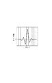
実際の画像にはノイズ成分があるため、上記のように光学伝達関数の完全な逆数をとって作成した回復フィルタを用いると、劣化画像の回復とともにノイズ成分が増幅されてしまう。したがって、一般には良好な画像は得られない。この改善方法の1つとして、図5に示すような画像データとノイズ信号の強度比(SNR)に応じて回復度合を制御する方法が知られている。この方法に使用される代表的な回復フィルタはウィナーフィルタと呼ばれている。この回復フィルタは、周波数ごとに、光学伝達関数の絶対値(MTF)が小さいほど増幅を抑制し、光学伝達関数の絶対値(MTF)が大きいほど増幅を強く行うものである。一般的に撮像光学系の光学伝達関数の絶対値(MTF)は、高周波側が低くなる(図5(a))ため、ウィナーフィルタは、画像の高周波側の回復度合を抑制する(図5(b))フィルタである。 Since an actual image has a noise component, using a recovery filter created by taking the complete reciprocal of the optical transfer function as described above will amplify the noise component as the degraded image is recovered. Therefore, generally a good image cannot be obtained. As one of the improvement methods, there is known a method for controlling the degree of recovery according to the intensity ratio (SNR) of image data and noise signal as shown in FIG. A typical recovery filter used in this method is called a Wiener filter. For each frequency, this recovery filter suppresses amplification as the absolute value (MTF) of the optical transfer function is smaller, and increases the amplification as the absolute value (MTF) of the optical transfer function is larger. In general, since the absolute value (MTF) of the optical transfer function of the imaging optical system is lower on the high frequency side (FIG. 5A), the Wiener filter suppresses the recovery degree on the high frequency side of the image (FIG. 5B). )) Filter.
回復フィルタは、画像が撮影された際の撮影条件に応じて最適なものを使用する必要がある。画像処理システム20では、図1に不図示の記憶部に撮像条件に応じた複数の回復フィルタ、あるいは複数の光学伝達関数を記憶させておく。図6は、記憶部に記憶された複数の回復フィルタ群の模式図を示している。記憶部には、焦点距離、絞り値(Fno)、撮影距離の3つの撮影条件を軸とした空間中に離散的に配置されるような回復フィルタが記憶されている。言い換えれば、空間中の各点(黒丸)の座標に対応する撮影条件によって撮影された画像を精度良く回復可能な回復フィルタが記憶されている。記憶部に記憶させる回復フィルタは、図6の黒丸で示したように各撮影条件に対して直交した格子点に対応するものに限られず、格子点から外れた点に対応する回復フィルタを記憶させてもよい。また、撮像条件のパラメータとして、図示するために3つの条件を用いて3次元図としたが、4つ以上の撮影条件のパラメータを対象とした4次元以上の空間であっても良い。
It is necessary to use an optimum recovery filter according to the shooting conditions when the image is shot. In the
回復フィルタの選択方法を説明する。図6において大きな白丸で示した撮影条件が、画像データの撮影条件であった場合、その極近傍の点に対応する回復フィルタが記憶されていた場合には、その回復フィルタを選択して回復処理に用いればよい。近傍の点に対応する回復フィルタが記憶されていなかった場合、一つの方法として、実際の撮像条件と記憶された撮影条件の空間中の距離を算出し、最も距離の短いものを選択する方法が挙げられる。例えば、図6では小さな白丸で示した位置の回復フィルタが選択される。また、別の方法として、回復フィルタを選択するにあたって、空間中の方向に応じて重み付けをすることができる。即ち、空間中の距離と重み付けの係数との積を評価関数として選択する方法が挙げられる。 A method for selecting a recovery filter will be described. If the shooting conditions indicated by the large white circles in FIG. 6 are the shooting conditions for image data, and if a recovery filter corresponding to a point in the immediate vicinity is stored, the recovery filter is selected and the recovery process is performed. Can be used. When a recovery filter corresponding to a nearby point is not stored, one method is to calculate the distance in the space between the actual imaging condition and the stored imaging condition and select the one with the shortest distance. Can be mentioned. For example, in FIG. 6, a recovery filter at a position indicated by a small white circle is selected. As another method, when selecting the recovery filter, weighting can be performed according to the direction in the space. That is, a method of selecting a product of a distance in space and a weighting coefficient as an evaluation function can be mentioned.
次に、カメラ信号処理部26が行うカメラ信号処理について説明する。カメラ信号処理とは、RAW画像データに対するデモザイキング処理、ホワイトバランス調整、エッジ強調、ノイズリダクション処理等の画像処理である。あるいは、光学伝達関数を使用する画像処理の中では、回復フィルタを使用せずに幾何学的な収差補正を行う、歪曲収差補正、倍率色収差補正、シェーディング補正等である。これらのカメラ信号処理は、2次元畳み込み演算の前後に必要に応じて挿入することができる。
Next, camera signal processing performed by the camera
ここで、回復処理は、画像の劣化過程が線形である方が劣化前の元画像に回復するための逆過程を高精度に処理できるため、入力画像は諸々の適応的な非線形処理を施されていないことが好ましい。したがって、回復処理はRAW画像データに対して行うことが好ましい。ただし、カメラ信号処理が実行された画像でも、色補間処理による劣化過程が線形であれば、回復フィルタの生成において、この劣化関数を考慮することで精度良く回復処理を行うことができる。また、回復の要求精度が低い場合や諸々の画像処理を施された画像しか入手できない場合には、カメラ信号処理が実行された画像や画像圧縮処理が行われた画像に対して回復処理を行っても構わない。 Here, the restoration process can process the inverse process for restoring the original image before degradation with higher accuracy when the degradation process of the image is linear. Therefore, the input image is subjected to various adaptive nonlinear processes. Preferably not. Therefore, it is preferable to perform the recovery process on the RAW image data. However, even in an image on which camera signal processing has been executed, if the deterioration process by color interpolation processing is linear, the recovery processing can be performed with high accuracy by taking this deterioration function into consideration when generating the recovery filter. If the required accuracy of recovery is low or only images that have undergone various image processing can be obtained, recovery processing is performed on images that have been subjected to camera signal processing or images that have been subjected to image compression processing. It doesn't matter.
次に撮像装置10の製造工程における製造ばらつきの調整について説明する。製造ばらつきは、撮像装置の光学伝達関数のばらつきを同時に引き起こしている。製造ばらつきのある撮像系に対して、例えば設計値に基づく特定の光学伝達関数を用いて、一定の回復度合いで回復処理を実行すると、撮像装置の性能ばらつきも回復度合いに応じて増幅される。図7は製造ばらつきのある撮像系に対して(図7(a))、設計値に基づいた光学伝達関数をもとに回復フィルタを作成して、回復処理を行った結果(図7(b))を表している。
Next, adjustment of manufacturing variation in the manufacturing process of the
この場合の回復フィルタはウィナーフィルタであるが、MTFの高周波の回復度合いが抑制されているため、中周波の回復度合いが最も大きく、この部分での性能ばらつきが大きくなっている。また、回復フィルタが光学伝達関数の逆数のフーリエ変換で与えられるので、撮像系の結像性能が低い、すなわちMTFが小さい場合には、回復フィルタの回復度合いが大きくなる。このような撮像装置では、製造ばらつきによる性能ばらつきが大きくなってしまう。 The recovery filter in this case is a Wiener filter. However, since the degree of recovery of the high frequency of the MTF is suppressed, the degree of recovery of the medium frequency is the largest, and the performance variation in this part is large. Further, since the recovery filter is given by the Fourier transform of the reciprocal of the optical transfer function, when the imaging performance of the imaging system is low, that is, when the MTF is small, the recovery degree of the recovery filter increases. In such an imaging apparatus, performance variations due to manufacturing variations become large.
この現象を解決するための方法としては、回復処理後の性能を評価しながら、回復フィルタにあった調整を行うことが考えられる。しかし、この方法では回復フィルタが特定のものである以上、根本的な性能ばらつきの改善は見込めない。根本的な解決のためには、製造される撮像装置の光学伝達関数を個別に測定し、それぞれの撮像装置にあった回復フィルタを作成することが考えられる。しかし、これを実現するためには、新しい製造ラインの構築と、製造コストの増大が予想され、現実的ではない。 As a method for solving this phenomenon, it is conceivable to adjust the recovery filter while evaluating the performance after the recovery process. However, in this method, since the recovery filter is specific, fundamental improvement in performance variation cannot be expected. As a fundamental solution, it is conceivable to individually measure the optical transfer function of the manufactured imaging device and create a recovery filter suitable for each imaging device. However, in order to realize this, construction of a new production line and an increase in production cost are expected, which is not realistic.
そこで本発明では、複数のパターン化された回復フィルタを使用することにより、性能ばらつきの改善を実現させた(図7(c))。従来の製造時における調整で残る性能ばらつきを見てみると、例えば画像の四隅で性能が異なる回転非対称な収差や画像の中心であるにもかかわらず発生する非対称な収差が目立つ。このように、調整で残る劣化特性は3〜10パターンの収差に分類することができることが分かった。本発明はこの点に着目し、数種類の回復フィルタを用いることで、製造ばらつきの増幅と製造コストの増大を抑制している。また、このとき使用する回復フィルタは上記のように画像中心に対して非対称な収差を補正するためのものであり、数種類の回復フィルタのうち少なくとも1つは画像中心に対して非対称なものを用意するのが望ましい。 Therefore, in the present invention, improvement in performance variation is realized by using a plurality of patterned recovery filters (FIG. 7C). When looking at the performance variations remaining after adjustment during conventional manufacturing, for example, rotationally asymmetrical aberrations that differ in performance at the four corners of the image and asymmetrical aberrations that occur despite the center of the image are conspicuous. Thus, it was found that the deterioration characteristics remaining after adjustment can be classified into 3 to 10 patterns of aberration. The present invention pays attention to this point and suppresses an increase in manufacturing variation and an increase in manufacturing cost by using several types of recovery filters. Also, the recovery filter used at this time is for correcting an asymmetrical aberration with respect to the image center as described above, and at least one of several types of recovery filters is asymmetric with respect to the image center. It is desirable to do.
具体的な調整方法としては、以下に詳述する評価手段、分類手段、回復手段、調整手段を実行する。なお、これらの手段は前記の順番に限定されるものではなく、必要に応じて順番を入れ替えて実行することができる。 As a specific adjustment method, an evaluation unit, a classification unit, a recovery unit, and an adjustment unit that are described in detail below are executed. Note that these means are not limited to the above order, and can be executed by changing the order as necessary.
評価手段は、調整における撮像系の性能劣化具合を評価する手段である。例えば、撮像装置の受光素子側に光学系の結像性能を評価するためのチャートを配置し、受光素子側から光を照射して被写体物体位置にセンサを置いて光学系を評価する方法がある。また、通常の撮影と同じように、被写体物体側にチャートを用意し、このチャートを実際の受光素子位置にセンサを置いて撮影することで、撮像系の性能を評価する方法がある。どちらの評価においても、使用されるセンサは評価に合わせて用意されればよく、結像性能の一断面を評価する場合にはラインセンサで構わないし、実際の撮影同様、全てのアジムス方向が評価したい場合には、2次元センサを使用すればよい。また、評価される結像性能は、製造誤差の生じた撮像系の結像性能そのものでもよいし、回復手段により回復された像の評価でもよい。さらに、調整手段により調整された像を逐次評価することも可能であり、上記の方法に限定されるものではない。 The evaluation means is a means for evaluating the performance deterioration degree of the imaging system in the adjustment. For example, there is a method in which a chart for evaluating the imaging performance of the optical system is arranged on the light receiving element side of the imaging apparatus, and the optical system is evaluated by irradiating light from the light receiving element side and placing the sensor at the object position . In addition, as in normal shooting, there is a method for evaluating the performance of the imaging system by preparing a chart on the object side and shooting the chart with a sensor placed at the actual light receiving element position. In either evaluation, the sensor to be used may be prepared according to the evaluation. When evaluating one section of the imaging performance, a line sensor may be used, and all azimuth directions are evaluated as in actual imaging. If this is desired, a two-dimensional sensor may be used. Further, the imaging performance to be evaluated may be the imaging performance itself of the imaging system in which a manufacturing error has occurred, or may be an evaluation of the image recovered by the recovery means. Furthermore, the images adjusted by the adjusting means can be sequentially evaluated, and the present invention is not limited to the above method.
分類手段は、調整における撮像装置の光学系の性能劣化具合を分類する手段である。上記の通り、撮像装置の劣化特性は最終的に数パターン(数種類)に分類することができる。分類手段では、光学系による性能劣化がどのパターンの劣化特性に最も近いのかを判断し、使用する回復フィルタに合わせた分類を行う。例えば、画像の四隅で性能が異なる回転非対称な収差が発生する場合には、四隅の結像スポットのサイズの最大値と最小値を比較することで分類の基準とすることができる。この分類手段は、評価手段により評価された結像性能に基づいて分類を行ってもよいし、調整手段により調整された像を元に分類を行ってもよく、これに限定されるものではない。撮像装置が最終的に出力する回復フィルタの分類情報は、この分類手段による分類に基づいて書き換えを行うことができる。これにより、撮像装置および画像処理システムで保持するフィルタ数を少なくすることができるので、撮像装置のメモリを効率的に使用することができる。 The classifying means is a means for classifying the degree of performance degradation of the optical system of the imaging apparatus in the adjustment. As described above, the deterioration characteristics of the imaging device can be finally classified into several patterns (several types). The classification means determines which pattern degradation characteristic is closest to the performance degradation due to the optical system, and performs classification according to the recovery filter to be used. For example, when rotationally asymmetric aberrations with different performance occur at the four corners of the image, the maximum and minimum values of the sizes of the imaging spots at the four corners can be compared to provide a classification criterion. The classification means may perform classification based on the imaging performance evaluated by the evaluation means, or may classify based on the image adjusted by the adjustment means, and is not limited to this. . The classification information of the recovery filter that is finally output by the imaging device can be rewritten based on the classification by the classification means. As a result, the number of filters held in the imaging apparatus and the image processing system can be reduced, so that the memory of the imaging apparatus can be used efficiently.
回復手段は、調整における撮像装置の撮像系の性能を回復する手段である。撮像系によるチャートの像は調整装置のセンサにより受光され電気的な信号に変換される。この信号を入力信号として、上述の回復処理と同様の画像処理を行うことができる。例えば被写体物体側におかれたチャートを受光素子面に配置されたセンサで受光する場合には、撮像装置に使用する回復フィルタが使用できる。また、受光素子側におかれたチャートを被写体物体面で受光する場合には、撮像装置に使用する回復フィルタに基づいて、調整用の回復フィルタを作成することで、回復処理を行うことができる。また、回復手段に使用される回復フィルタは、製造ばらつきの生じた撮像装置の光学伝達関数を平均したものを使用する。ただし、この場合には、平均の光学性能よりも高い性能のレンズに関しては、過剰な回復が行われることがある。このような場合には、製造ばらつきのある結像性能のうち最も性能の高い撮像系の光学伝達関数を基に回復フィルタを用いればよい。回復フィルタに関しては、製造ばらつきを調整した最終的な性能が最も高くなればよく、これらに限定されるものではない。この回復手段は、製造誤差の生じた撮像系の結像性能そのものを回復してもよいし、評価手段により評価された像に対して回復処理を行ってもよく、上記の方法に限定されるものではない。 The recovery means is means for recovering the performance of the imaging system of the imaging apparatus in adjustment. The chart image by the imaging system is received by a sensor of the adjusting device and converted into an electrical signal. By using this signal as an input signal, image processing similar to the above-described recovery processing can be performed. For example, when a chart placed on the object side is received by a sensor arranged on the light receiving element surface, a recovery filter used for the imaging apparatus can be used. Further, when the chart placed on the light receiving element side is received by the object surface, the recovery process can be performed by creating a recovery filter for adjustment based on the recovery filter used in the imaging device. . Further, the recovery filter used for the recovery means is an averaged optical transfer function of the imaging device in which the manufacturing variation has occurred. However, in this case, an excessive recovery may be performed for a lens having a performance higher than the average optical performance. In such a case, a recovery filter may be used based on the optical transfer function of the imaging system having the highest performance among the imaging performance with manufacturing variations. Regarding the recovery filter, it is only necessary that the final performance after adjusting the manufacturing variation is the highest, and the present invention is not limited to these. This recovery means may recover the imaging performance itself of the imaging system in which a manufacturing error has occurred, or may perform recovery processing on the image evaluated by the evaluation means, and is limited to the above method. It is not a thing.
調整手段は、撮像装置の撮像系の性能を調整する手段である。この調整手段によって撮像装置内の調整部を変化させることにより、光学伝達関数を連続的かつ微少に変化させることができる。設計値に対して製造誤差のある撮像装置との間の光学伝達関数のずれを打ち消す(低減する)ように調整部を変化させる。調整部とは、撮像装置の撮像系の一部、あるいは撮像系全体、あるいは受光素子である。具体的な調整部の変化方法としては、調整部のシフト(偏心、並進)、チルト(傾斜)を与えたり、調整部を光軸方向に段階的に移動させたりする方法がある。これらは機械的な変化により光学伝達関数を変化させているが、位相変調素子や液晶レンズのように電気的に光学伝達関数を変化させても構わない。 The adjusting means is means for adjusting the performance of the imaging system of the imaging apparatus. By changing the adjustment unit in the imaging apparatus by this adjustment means, the optical transfer function can be changed continuously and minutely. The adjustment unit is changed so as to cancel (reduce) the shift of the optical transfer function between the imaging device and the design value having a manufacturing error. The adjustment unit is a part of the imaging system of the imaging apparatus, the entire imaging system, or a light receiving element. As a specific method of changing the adjustment unit, there are a method of giving shift (eccentricity, translation) and tilt (tilting) of the adjustment unit, or moving the adjustment unit stepwise in the optical axis direction. These change the optical transfer function by mechanical change, but the optical transfer function may be changed electrically like a phase modulation element or a liquid crystal lens.
また、調整手段は、製造誤差の生じた撮像系の結像性能に基づいて調整を行っても良いし、回復手段により回復された像に基づいて(回復された像が所望の性能を得られるように)調整を行っても良い。 The adjustment unit may perform adjustment based on the imaging performance of the imaging system in which a manufacturing error has occurred, or based on the image recovered by the recovery unit (the recovered image can obtain desired performance). Adjustments may be made.
(実施形態2)
以下、図8を参照して、本発明の第2の実施形態による、画像処理システムについて説明する。実施形態1と異なる点は、分類情報21が画像データ22に付与されている点である。本実施形態では、撮像装置10を画像処理システム20に接続した際に、撮像装置10の製造ばらつきによる性能ばらつきの分類情報21が記録されたRAWデータの画像データ22が送られる。画像処理システム20では、回復処理部23において分類情報21を元に回復フィルタ24を特定する。2次元畳み込み演算部25において、この回復フィルタ24を画像データ22に対して2次元畳み込み演算をすることで、回復処理を行っている。回復画像は、カメラ信号処理部26によってデモザイキング処理、ホワイトバランス調整、エッジ強調、ノイズリダクション処理等のカメラ信号処理を実行し、出力画像27が出力される。
(Embodiment 2)
The image processing system according to the second embodiment of the present invention will be described below with reference to FIG. The difference from the first embodiment is that the
(実施形態3)
以下、図9を参照して、本発明の第3の実施形態による、画像処理システム20について説明する。本実施形態が実施形態1と異なる点は、外部から分類情報21が送られる点である。本実施形態では、撮像装置10を画像処理システム20に接続した際に、すでに撮像装置内の画像処理ICによってデモザイキング処理、ホワイトバランス調整、エッジ強調、ノイズリダクション処理等のカメラ信号処理が実行された画像データ22が送られる。一方で、分類情報21は、撮像装置10からの画像データ22とは別に、インターネット経由で取得される。あるいは、分類情報21を有する別の通信装置のとの間の赤外線通信や、ブルートゥース等による通信により、画像処理システム20に送られる。画像処理システム20では、回復処理部23において、分類情報21を元に不図示の記憶部に記憶された回復フィルタ24を特定する。回復処理部23において、この回復フィルタ24と画像データ22とを2次元畳み込み演算部25が2次元畳み込み演算を行うことで回復処理を行い、出力画像27を出力する。
(Embodiment 3)
Hereinafter, an
(実施形態4)
以下、図10を参照して、本発明の第4の実施形態による、画像処理システムについて説明する。実施形態1と異なる点は、画像処理システム20が、記録媒体101から分類情報を取得する点である。本実施形態では撮像装置10を画像処理システム20に接続した際に、RAWデータの画像データ22が送られる。一方で、USBメモリ等の記録媒体101により記憶された分類情報21が画像処理システム20に送られる。画像処理システム20では、回復処理部23において分類情報21を元に回復フィルタ24を特定し、回復フィルタ24を画像データ22に2次元畳み込み演算することで回復処理を行っている。カメラ信号処理部26において、回復画像は、デモザイキング処理、ホワイトバランス調整、エッジ強調、ノイズリダクション処理等のカメラ信号処理を実行し、出力画像が出力される。
(Embodiment 4)
Hereinafter, an image processing system according to a fourth embodiment of the present invention will be described with reference to FIG. The difference from the first embodiment is that the
(実施形態5)
以下、図11を参照して、本発明の第5の実施形態による、画像処理システムについて説明する。実施形態1と異なる点は、撮像装置10が分類情報21を持っており、撮像装置10の中で回復フィルタ24が作成される。撮像装置10を画像処理システム20に接続した際に、この回復フィルタ24と、デモザイキング処理、ホワイトバランス調整、エッジ強調、ノイズリダクション処理等のカメラ信号処理が実行された画像データ22が送られる。画像処理システム20では、回復処理部23において、回復フィルタ24を画像データ22に2次元畳み込み演算することで回復処理を行い、出力画像27を出力する。
(Embodiment 5)
Hereinafter, an image processing system according to the fifth embodiment of the present invention will be described with reference to FIG. The difference from the first embodiment is that the
この方法では、回復フィルタと画像データが別々に送られることが特徴である。分類情報により特定される回復フィルタは撮像装置固有の情報である。このため、撮像装置の購入時のような特定のタイミングで回復フィルタを画像処理システムに記憶させ、この回復フィルタと通常撮影を行った画像データを下に画像処理を行うことができる。従って毎回、回復フィルタのやり取りをする必要がなく、効率的である。 This method is characterized in that the recovery filter and the image data are sent separately. The recovery filter specified by the classification information is information specific to the imaging apparatus. For this reason, the recovery filter can be stored in the image processing system at a specific timing, such as when the imaging apparatus is purchased, and image processing can be performed on the recovery filter and image data that has been captured normally. Therefore, it is not necessary to exchange the recovery filter every time, which is efficient.
(実施形態6)
以下、図12を参照して、本発明の第6の実施形態による、画像処理システムについて説明する。実施形態1と異なる点は、撮像装置10が分類情報21を持っており、撮像装置10の中で回復フィルタ24が作成される。撮像装置10を画像処理システム20に接続した際に、回復フィルタ24が記録されたRAWデータの画像データ22が送られる。画像処理システム20では、回復フィルタ24を画像データ22に2次元畳み込み演算することで回復処理を行っている。回復された画像は、デモザイキング処理、ホワイトバランス調整、エッジ強調、ノイズリダクション処理等のカメラ信号処理が実行され、出力画像27が出力される。
(Embodiment 6)
Hereinafter, an image processing system according to a sixth embodiment of the present invention will be described with reference to FIG. The difference from the first embodiment is that the
この方法では、画像処理システムに送られる情報が1つにまとめられているため、データのやり取りが簡潔であることが特徴である。また、回復フィルタが記録されているので画像処理システムの演算が少なくすみ、画像処理に関する時間を短縮することができる。 This method is characterized in that the exchange of data is simple because the information sent to the image processing system is combined into one. Further, since the recovery filter is recorded, the calculation of the image processing system can be reduced, and the time relating to the image processing can be shortened.
(実施形態7)
以下、図13を参照して、本発明の第7の実施形態による、画像処理システムについて説明する。実施形態1と異なる点は、外部から回復フィルタを取得する点である。インターネット経由で複数の回復フィルタの中から特定の回復フィルタを選んでダウンロードしたり、あるいは別機器からの通信を利用して特定の回復フィルタを取得したりすることができる。
(Embodiment 7)
The image processing system according to the seventh embodiment of the present invention will be described below with reference to FIG. The difference from the first embodiment is that a recovery filter is acquired from the outside. A specific recovery filter can be selected and downloaded from a plurality of recovery filters via the Internet, or a specific recovery filter can be acquired using communication from another device.
(実施形態8)
以下、図14を参照して、本発明の第8の実施形態による、画像処理システムについて説明する。実施形態1と異なる点は、記録媒体101から回復フィルタ24を取得する点と、カメラ信号処理部26によるカメラ信号処理が2次元畳み込み演算よりも前に行われる点である。
(Embodiment 8)
The image processing system according to the eighth embodiment of the present invention will be described below with reference to FIG. The difference from the first embodiment is that the
10 撮像装置
20 画像処理システム
21 分類情報
22 画像データ
23 回復処理
24 回復フィルタ
25 2次元畳み込み演算
DESCRIPTION OF
Claims (10)
前記分類情報に対応する回復フィルタを用いて、前記撮像装置を用いて撮像された画像の回復画像を生成するステップを情報処理装置に実行させることを特徴とするプログラム。 Variations in the optical performance of an imaging device for capturing an image via the imaging system, the classification was classified information in accordance with the pattern of aberrations of the imaging system and the image data of the captured image using the imaging device A step to obtain,
A program that causes an information processing device to execute a step of generating a recovery image of an image captured using the imaging device using a recovery filter corresponding to the classification information.
前記分類情報に対応する回復フィルタを用いて、前記撮像装置を用いて撮像された画像の回復画像を生成するステップを情報処理装置に実行させることを特徴とするプログラム。A program that causes an information processing device to execute a step of generating a recovery image of an image captured using the imaging device using a recovery filter corresponding to the classification information.
前記画像処理装置により生成された前記回復画像を表示する表示部を有することを特徴とする画像処理システム。 The image processing apparatus according to any one of claims 1 to 5 ,
An image processing system comprising a display unit for displaying the restored image generated by the image processing apparatus.
Priority Applications (2)
| Application Number | Priority Date | Filing Date | Title |
|---|---|---|---|
| JP2011201820A JP5451704B2 (en) | 2010-12-22 | 2011-09-15 | Image processing apparatus, image processing method, program, and image processing system |
| US13/330,284 US20120162485A1 (en) | 2010-12-22 | 2011-12-19 | Image processing apapratus, image processing method, and program, and image processing system |
Applications Claiming Priority (3)
| Application Number | Priority Date | Filing Date | Title |
|---|---|---|---|
| JP2010286524 | 2010-12-22 | ||
| JP2010286524 | 2010-12-22 | ||
| JP2011201820A JP5451704B2 (en) | 2010-12-22 | 2011-09-15 | Image processing apparatus, image processing method, program, and image processing system |
Publications (3)
| Publication Number | Publication Date |
|---|---|
| JP2012146281A JP2012146281A (en) | 2012-08-02 |
| JP2012146281A5 JP2012146281A5 (en) | 2013-10-03 |
| JP5451704B2 true JP5451704B2 (en) | 2014-03-26 |
Family
ID=46316255
Family Applications (1)
| Application Number | Title | Priority Date | Filing Date |
|---|---|---|---|
| JP2011201820A Expired - Fee Related JP5451704B2 (en) | 2010-12-22 | 2011-09-15 | Image processing apparatus, image processing method, program, and image processing system |
Country Status (2)
| Country | Link |
|---|---|
| US (1) | US20120162485A1 (en) |
| JP (1) | JP5451704B2 (en) |
Families Citing this family (6)
| Publication number | Priority date | Publication date | Assignee | Title |
|---|---|---|---|---|
| US9674431B2 (en) | 2013-02-01 | 2017-06-06 | Canon Kabushiki Kaisha | Image pickup apparatus, image processing apparatus, image processing method, and non-transitory computer-readable storage medium |
| CN108040215B (en) * | 2013-02-01 | 2021-03-26 | 佳能株式会社 | Image pickup apparatus, image processing method, and computer readable medium |
| JP5844940B2 (en) * | 2013-03-18 | 2016-01-20 | 富士フイルム株式会社 | Restoration filter generation device and method, image processing device and method, imaging device, program, and recording medium |
| JP6327860B2 (en) * | 2014-01-06 | 2018-05-23 | キヤノン株式会社 | Imaging device and interchangeable lens |
| US10290082B2 (en) * | 2016-08-23 | 2019-05-14 | Canon Kabushiki Kaisha | Image processing apparatus, imaging apparatus, image processing method, and storage medium for performing a restoration process for an image |
| CN111239740A (en) * | 2020-01-20 | 2020-06-05 | 上海眼控科技股份有限公司 | Method and equipment for removing ray noise |
Family Cites Families (9)
| Publication number | Priority date | Publication date | Assignee | Title |
|---|---|---|---|---|
| JP2004239962A (en) * | 2003-02-03 | 2004-08-26 | Nikon Corp | Shake correction camera system, shake correction camera, image recovering device and shake correction program |
| US8049798B2 (en) * | 2005-12-27 | 2011-11-01 | Kyocera Corporation | Imaging device and image processing method |
| JP4436427B2 (en) * | 2006-05-16 | 2010-03-24 | パナソニック株式会社 | Imaging device and semiconductor circuit element |
| JP2008109230A (en) * | 2006-10-23 | 2008-05-08 | Kyocera Corp | Imaging apparatus and image processing method |
| US9007478B2 (en) * | 2007-01-09 | 2015-04-14 | Capso Vision, Inc. | Methods to compensate manufacturing variations and design imperfections in a capsule camera |
| JP4813446B2 (en) * | 2007-11-16 | 2011-11-09 | 富士フイルム株式会社 | IMAGING SYSTEM, IMAGING DEVICE EQUIPPED WITH THIS IMAGING SYSTEM, PORTABLE TERMINAL DEVICE, IN-VEHICLE DEVICE, MEDICAL DEVICE, AND METHOD FOR PRODUCING IMAGING SYSTEM |
| US8294807B2 (en) * | 2009-01-23 | 2012-10-23 | Ricoh Co., Ltd. | Imaging system with variable opto-mechanical system, aberrated optics and compensating filter bank |
| JP2010177918A (en) * | 2009-01-28 | 2010-08-12 | Toshiba Corp | Image recording apparatus and manufacturing apparatus of the same |
| JP5488143B2 (en) * | 2010-04-07 | 2014-05-14 | ソニー株式会社 | Imaging apparatus and imaging signal correction method |
-
2011
- 2011-09-15 JP JP2011201820A patent/JP5451704B2/en not_active Expired - Fee Related
- 2011-12-19 US US13/330,284 patent/US20120162485A1/en not_active Abandoned
Also Published As
| Publication number | Publication date |
|---|---|
| US20120162485A1 (en) | 2012-06-28 |
| JP2012146281A (en) | 2012-08-02 |
Similar Documents
| Publication | Publication Date | Title |
|---|---|---|
| US9007482B2 (en) | Image processing method, image processing apparatus, image pickup apparatus, and non-transitory computer-readable storage medium | |
| JP4942216B2 (en) | Image processing method, image processing apparatus, imaging apparatus, and program | |
| JP5409589B2 (en) | Image processing method, image processing program, image processing apparatus, and imaging apparatus | |
| JP5153846B2 (en) | Image processing apparatus, imaging apparatus, image processing method, and program | |
| JP5264968B2 (en) | Image processing apparatus, image processing method, imaging apparatus, and image processing program | |
| JP5451704B2 (en) | Image processing apparatus, image processing method, program, and image processing system | |
| JP6045185B2 (en) | Image processing apparatus, image processing method, and program | |
| JP5535053B2 (en) | Image processing apparatus and image processing method | |
| JP2013084247A (en) | Image processing apparatus and method | |
| JP2011215707A (en) | Image processing apparatus, imaging apparatus, image processing method, and program | |
| JP5344648B2 (en) | Image processing method, image processing apparatus, imaging apparatus, and image processing program | |
| JP5587264B2 (en) | ADJUSTMENT METHOD, ADJUSTMENT DEVICE, AND IMAGING DEVICE MANUFACTURING METHOD | |
| JP2011217087A (en) | Image processor and imaging apparatus using the same | |
| JP5730036B2 (en) | Image processing apparatus, imaging apparatus, image processing method, and program. | |
| JP2015115733A (en) | Image processing method, image processor, imaging device, and image processing program | |
| JP6821526B2 (en) | Image processing method, image processing device, imaging device, and program | |
| JP5425135B2 (en) | Image processing method, image processing apparatus, imaging apparatus, and image processing program | |
| JP5541750B2 (en) | Image processing apparatus, imaging apparatus, image processing method, and program | |
| JP5268533B2 (en) | Image processing method, image processing apparatus, imaging apparatus, and image processing program | |
| JP2012156715A (en) | Image processing device, imaging device, image processing method, and program | |
| JP5425136B2 (en) | Image processing method, image processing apparatus, imaging apparatus, and image processing program | |
| JP5611439B2 (en) | Image processing method, image processing apparatus, imaging apparatus, and image processing program | |
| JP5344647B2 (en) | Image processing method, image processing apparatus, and image processing program | |
| JP6486076B2 (en) | Image processing apparatus and image processing method | |
| JP2017123532A (en) | Image processing device, imaging device, image processing method, image processing program and recording medium |
Legal Events
| Date | Code | Title | Description |
|---|---|---|---|
| A521 | Request for written amendment filed |
Free format text: JAPANESE INTERMEDIATE CODE: A523 Effective date: 20130821 |
|
| A621 | Written request for application examination |
Free format text: JAPANESE INTERMEDIATE CODE: A621 Effective date: 20130821 |
|
| A871 | Explanation of circumstances concerning accelerated examination |
Free format text: JAPANESE INTERMEDIATE CODE: A871 Effective date: 20130821 |
|
| A975 | Report on accelerated examination |
Free format text: JAPANESE INTERMEDIATE CODE: A971005 Effective date: 20130905 |
|
| A131 | Notification of reasons for refusal |
Free format text: JAPANESE INTERMEDIATE CODE: A131 Effective date: 20130917 |
|
| A521 | Request for written amendment filed |
Free format text: JAPANESE INTERMEDIATE CODE: A523 Effective date: 20131118 |
|
| TRDD | Decision of grant or rejection written | ||
| A01 | Written decision to grant a patent or to grant a registration (utility model) |
Free format text: JAPANESE INTERMEDIATE CODE: A01 Effective date: 20131203 |
|
| A61 | First payment of annual fees (during grant procedure) |
Free format text: JAPANESE INTERMEDIATE CODE: A61 Effective date: 20131226 |
|
| R151 | Written notification of patent or utility model registration |
Ref document number: 5451704 Country of ref document: JP Free format text: JAPANESE INTERMEDIATE CODE: R151 |
|
| LAPS | Cancellation because of no payment of annual fees |