JP5449848B2 - Fuel cell stack - Google Patents
Fuel cell stack Download PDFInfo
- Publication number
- JP5449848B2 JP5449848B2 JP2009109452A JP2009109452A JP5449848B2 JP 5449848 B2 JP5449848 B2 JP 5449848B2 JP 2009109452 A JP2009109452 A JP 2009109452A JP 2009109452 A JP2009109452 A JP 2009109452A JP 5449848 B2 JP5449848 B2 JP 5449848B2
- Authority
- JP
- Japan
- Prior art keywords
- fuel cell
- cell stack
- communication hole
- fuel
- vehicle
- Prior art date
- Legal status (The legal status is an assumption and is not a legal conclusion. Google has not performed a legal analysis and makes no representation as to the accuracy of the status listed.)
- Expired - Fee Related
Links
Images


Classifications
-
- Y—GENERAL TAGGING OF NEW TECHNOLOGICAL DEVELOPMENTS; GENERAL TAGGING OF CROSS-SECTIONAL TECHNOLOGIES SPANNING OVER SEVERAL SECTIONS OF THE IPC; TECHNICAL SUBJECTS COVERED BY FORMER USPC CROSS-REFERENCE ART COLLECTIONS [XRACs] AND DIGESTS
- Y02—TECHNOLOGIES OR APPLICATIONS FOR MITIGATION OR ADAPTATION AGAINST CLIMATE CHANGE
- Y02E—REDUCTION OF GREENHOUSE GAS [GHG] EMISSIONS, RELATED TO ENERGY GENERATION, TRANSMISSION OR DISTRIBUTION
- Y02E60/00—Enabling technologies; Technologies with a potential or indirect contribution to GHG emissions mitigation
- Y02E60/30—Hydrogen technology
- Y02E60/50—Fuel cells
-
- Y—GENERAL TAGGING OF NEW TECHNOLOGICAL DEVELOPMENTS; GENERAL TAGGING OF CROSS-SECTIONAL TECHNOLOGIES SPANNING OVER SEVERAL SECTIONS OF THE IPC; TECHNICAL SUBJECTS COVERED BY FORMER USPC CROSS-REFERENCE ART COLLECTIONS [XRACs] AND DIGESTS
- Y02—TECHNOLOGIES OR APPLICATIONS FOR MITIGATION OR ADAPTATION AGAINST CLIMATE CHANGE
- Y02T—CLIMATE CHANGE MITIGATION TECHNOLOGIES RELATED TO TRANSPORTATION
- Y02T90/00—Enabling technologies or technologies with a potential or indirect contribution to GHG emissions mitigation
- Y02T90/10—Technologies relating to charging of electric vehicles
- Y02T90/16—Information or communication technologies improving the operation of electric vehicles
Description
本発明は、電解質膜の両側に一対の電極を設けた電解質膜・電極構造体とセパレータとが積層されるとともに、平面視で長方形状を有する燃料電池スタックに関する。 The invention, together with the separator and the membrane electrode assembly in which a pair of electrodes on both sides of the electrolyte membrane is a product layer, a fuel cell stack having a rectangular shape in plan view.
例えば、固体高分子型燃料電池は、高分子イオン交換膜からなる電解質膜の両側に、それぞれアノード側電極及びカソード側電極を配設した電解質膜・電極構造体(MEA)を、セパレータによって挟持した単位セルを備えている。この種の燃料電池は、通常、所定の数の単位セルを積層することにより、燃料電池スタックとして使用されている。 For example, in a polymer electrolyte fuel cell, an electrolyte membrane / electrode structure (MEA) in which an anode side electrode and a cathode side electrode are disposed on both sides of an electrolyte membrane made of a polymer ion exchange membrane is sandwiched by separators. A unit cell is provided. This type of fuel cell is normally used as a fuel cell stack by stacking a predetermined number of unit cells.
燃料電池は、例えば、車載用として所望の発電力を得るために、所定数(例えば、数十〜数百)の単位セルを積層した燃料電池スタックとして使用されている。この種の燃料電池スタックでは、各単位セルが所望の発電性能を有しているか否かを検出する必要がある。このため、一般的には、セパレータに設けられたセル電圧端子を電圧検出装置(セル電圧モニタ)に接続して、発電時の各単位セル毎のセル電圧を検出する作業が行われている。 The fuel cell is used as a fuel cell stack in which a predetermined number (for example, several tens to several hundreds) of unit cells are stacked in order to obtain a desired power generation for in-vehicle use, for example. In this type of fuel cell stack, it is necessary to detect whether each unit cell has a desired power generation performance. For this reason, generally, the operation | work which detects the cell voltage for every unit cell at the time of electric power generation by connecting the cell voltage terminal provided in the separator to the voltage detection apparatus (cell voltage monitor) is performed.
例えば、特許文献1では、図10に示すように、固体高分子型の燃料電池スタック1を備えており、この燃料電池スタック1は、複数のセル2を積層して構成されている。セル2は、2セル毎に1ユニットとして構成されるとともに、各ユニットには、電力測定端子3が配置されている。
For example, in Patent Document 1, as shown in FIG. 10, a solid polymer fuel cell stack 1 is provided, and the fuel cell stack 1 is configured by stacking a plurality of
燃料電池スタック1は、セル2の積層方向両端にエンドプレート4a、4bが配置され、前記エンドプレート4a、4bの各角部同士は、屈曲形状を有する連結板5に固着されることにより、前記セル2には、積層方向への荷重が付与されている。燃料電池スタック1の側部には、外方に突出して電圧測定端子3が配列されるとともに、前記電圧測定端子3には、図示しないコネクタが接続されている。
In the fuel cell stack 1,
燃料電池スタック1は、鉛直方向(矢印X方向)上端側に、空気給気通路6a、冷媒水通路7及び水素給気通路8aが設けられているとともに、鉛直方向下端側に、空気排気通路6b、冷媒水通路7及び水素排気通路8bが設けられている。
The fuel cell stack 1 is provided with an
ところで、上記の燃料電池スタック1では、例えば、各セル2の積層方向を車長方向(矢印Z方向)に沿って車両に搭載すると、各電圧測定端子3が車幅方向(矢印Y方向)に突出してしまう。このため、燃料電池スタック1は、車幅方向に大型化し、比較的幅狭な、例えば、センターコンソール内に前記燃料電池スタック1を収容することができないという問題がある。
By the way, in the fuel cell stack 1 described above, for example, when the stacking direction of the
一方、燃料電池スタック1を、各電圧測定端子3が上方に向かうように、90゜だけ回転させた状態で、車両に搭載することが考えられる。しかしながら、空気給気通路6a、冷媒水通路7及び水素給気通路8aと、空気排気通路6b、冷媒水通路7及び水素排気通路8bとは、左右に配置されるため、実質的に車幅方向の寸法が長尺化してしまう。これにより、燃料電池スタック1を幅狭なスペースに有効に収容させることができないという問題がある。
On the other hand, it is conceivable that the fuel cell stack 1 is mounted on a vehicle in a state where the fuel cell stack 1 is rotated by 90 ° so that each
また、燃料電池スタック1では、各電圧測定端子3の近傍に水素給気通路8aが設けられている。従って、電圧測定端子3が、水素給気通路8aを流通する水素に影響を与えるおそれがある。
In the fuel cell stack 1, a
なお、上記の問題は、車載用燃料電池に限定されるものではなく、定置用燃料電池であっても、収容スペースの効率利用を図る際に、懸案となっている。 The above-mentioned problem is not limited to the on-vehicle fuel cell, and even a stationary fuel cell is a concern when the storage space is used efficiently.
本発明はこの種の課題を解決するものであり、全体の幅寸法を有効に短尺化するとともに、電流取り出し端子が燃料ガスに影響を与えることを可及的に阻止することが可能な燃料電池スタックを提供することを目的とする。 The present invention solves this type of problem, and can effectively shorten the overall width dimension and prevent the current extraction terminal from affecting the fuel gas as much as possible. The purpose is to provide a stack.
本発明は、電解質膜の両側に一対の電極を設けた電解質膜・電極構造体とセパレータとが積層されるとともに、平面視で長方形状を有する燃料電池スタックに関するものである。 The present invention includes a separator and the membrane electrode assembly in which a pair of electrodes on both sides of the electrolyte membrane with the product layer, to a fuel cell stack having a rectangular shape in plan view.
この燃料電池スタックは、長方形状の短辺側一方の角部には、切り欠き部を設け、前記切り欠き部に膨出して外部へ電流を取り出す電流取り出し端子が設けられるとともに、前記長方形状の短辺側他方の角部には、燃料ガスを流通させる燃料ガス連通孔が設けられている。 The fuel cell stack is provided with a notch at one corner on the short side of the rectangular shape, and a current extraction terminal that bulges into the notch and extracts current from the outside. A fuel gas communication hole through which fuel gas flows is provided at the other corner on the short side.
また、電流取り出し端子は、長方形状の短辺側の幅寸法内に突出形成されることが好ましい。 Moreover, it is preferable that the current extraction terminal is formed so as to protrude within the width dimension on the short side of the rectangular shape.
さらに、燃料電池スタックは、車両に搭載されるとともに、長方形状の長辺側は、前記車両の前後方向に沿って配設され、且つ、電流取り出し端子は、前記車両の後方側に向かって配設されることが好ましい。 Further, the fuel cell stack is mounted on the vehicle, the long side of the rectangular shape is disposed along the front-rear direction of the vehicle, and the current extraction terminal is disposed toward the rear side of the vehicle. It is preferable to be provided.
さらにまた、この燃料電池スタックは、燃料電池スタックの車両の後方側には、電流取り出し端子に接続される装置が配設されることが好ましい。 Furthermore, in the fuel cell stack, it is preferable that a device connected to the current extraction terminal is disposed on the rear side of the vehicle of the fuel cell stack.
本発明によれば、燃料電池スタックの短辺側一方の角部に、電流取り出し端子が設けられるため、前記燃料電池スタックの長辺側には、前記電流取り出し端子の他、コネクタやケーブル等が配置されない構造を採用することが可能になる。従って、燃料電池スタックは、短辺側の幅寸法を可及的に小型化することができ、例えば、幅狭なスペースに効果的に収容することが可能になり、収容スペースの効率利用が容易に図られる。 According to the present invention, since the current extraction terminal is provided at one corner of the short side of the fuel cell stack, a connector, a cable, and the like are provided on the long side of the fuel cell stack in addition to the current extraction terminal. It is possible to adopt a structure that is not arranged. Therefore, the fuel cell stack can reduce the width dimension on the short side as much as possible. For example, the fuel cell stack can be effectively accommodated in a narrow space, and the efficient utilization of the accommodation space is easy. Is envisioned.
また、燃料電池スタックは、長方形状の短辺側一方の角部に、電流取り出し端子が設けられるとともに、前記長方形状の短辺側他方の角部に、燃料ガス連通孔が設けられている。このため、電流取り出し端子は、燃料ガス連通孔から離間しており、前記電流取り出し端子が前記燃料ガス連通孔を流通する燃料ガスに影響を与えることを可及的に阻止することができる。 The fuel cell stack is provided with a current extraction terminal at one corner of the rectangular short side and a fuel gas communication hole at the other corner of the rectangular short side. For this reason, the current extraction terminal is separated from the fuel gas communication hole, and it is possible to prevent the current extraction terminal from affecting the fuel gas flowing through the fuel gas communication hole as much as possible.
図1に示すように、本発明の第1の実施形態に係る燃料電池スタック10は、燃料電池車両12に搭載される。燃料電池車両12は、車室14内に左右のフロントシート(運転席及び助手席)16a、16b間に位置して、センターコンソール18を設ける(図1及び図2参照)。センターコンソール18は、燃料電池車両12の車長方向(矢印L方向)に延在するとともに、前記センターコンソール18内に、燃料電池スタック10と電圧測定装置(ECU)20とが収容される。
As shown in FIG. 1, the
図3に示すように、燃料電池スタック10は、平面視で長方形状を有するとともに、複数の燃料電池22が矢印A方向(鉛直方向)に積層される。燃料電池22の積層方向下端(一端)には、第1ターミナルプレート24a、第1絶縁プレート26a及び第1エンドプレート28aが積層される一方、積層方向上端(他端)には、第2ターミナルプレート24b、第2絶縁プレート26b及び第2エンドプレート28bが積層される。
As shown in FIG. 3, the
図4に示すように、燃料電池22は、電解質膜・電極構造体30が、第1及び第2セパレータ32、34に挟持される。第1及び第2セパレータ32、34は、例えば、鋼板、ステンレス鋼板、アルミニウム板、あるいはめっき処理鋼板等の金属セパレータやカーボンセパレータにより構成される。
As shown in FIG. 4, the
燃料電池22の矢印B方向(図4中、水平方向)の一端縁部、すなわち、長方形状の一方の短辺側には、積層方向である矢印A方向に互いに連通して、酸化剤ガス、例えば、酸素含有ガスを供給するための酸化剤ガス入口連通孔36a、及び燃料ガス、例えば、水素含有ガスを供給するための燃料ガス入口連通孔38aが、矢印C方向(水平方向)に配列して設けられる。
One end edge of the
燃料電池22の矢印B方向の他端縁部、すなわち、長方形状の他方の短辺側には、矢印A方向に互いに連通して、燃料ガスを排出するための燃料ガス出口連通孔38b、及び酸化剤ガスを排出するための酸化剤ガス出口連通孔36bが、矢印C方向に配列して設けられる。
The other end edge of the
燃料電池22の矢印C方向の両端縁部には、冷却媒体を供給するための冷却媒体入口連通孔40a、及び前記冷却媒体を排出するための冷却媒体出口連通孔40bが設けられる。
A cooling medium
第1セパレータ32の電解質膜・電極構造体30に向かう面32aには、酸化剤ガス入口連通孔36aと酸化剤ガス出口連通孔36bとに連通する酸化剤ガス流路42が設けられる。
An oxidant
第2セパレータ34の電解質膜・電極構造体30に向かう面34aには、燃料ガス入口連通孔38aと燃料ガス出口連通孔38bとに連通する燃料ガス流路44が設けられる。
A
互いに隣接する燃料電池22を構成する第1セパレータ32の面32bと、第2セパレータ34の面34bとの間には、冷却媒体入口連通孔40aと冷却媒体出口連通孔40bとを連通する冷却媒体流路46が設けられる。
A cooling medium that connects the cooling medium
第1セパレータ32の面32a、32bには、第1シール部材48が、一体的又は個別に設けられるとともに、第2セパレータ34の面34a、34bには、第2シール部材50が、一体的に又は個別に設けられる。
A
第1及び第2シール部材48、50は、例えば、EPDM、NBR、フッ素ゴム、シリコンゴム、フロロシリコンゴム、ブチルゴム、天然ゴム、スチレンゴム、クロロプレーン、又はアクリルゴム等のシール材、クッション材、あるいはパッキン材を使用する。
The first and
第1セパレータ32は、長方形状の各短辺側一方の角部には、切り欠き部52a、52bを設けるとともに、前記切り欠き部52a、52bに膨出して電圧測定に使用される電圧測定端子(電流取り出し端子)54a、54bが設けられる。第1セパレータ32は、長方形状の各短辺側他方の角部には、燃料ガス入口連通孔38a及び燃料ガス出口連通孔38bが設けられる。
The
電圧測定端子54a、54bは、長方形状の短辺側の幅寸法H内に突出形成される。なお、長方形状の一方の短辺側一方の角部にのみ、例えば、酸化剤ガス入口連通孔36aに隣接する角部にのみ、電圧測定端子54aを設けるとともに、電圧測定端子54bは、削除してもよい。
The
第2セパレータ34は、同様に、長方形状の各短辺側一方の角部には、切り欠き部56a、56bを設けるとともに、前記切り欠き部56a、56bに膨出して電圧測定に使用される電圧測定端子58a、58bが設けられる。第2セパレータ34は、長方形状の各短辺側他方の角部には、燃料ガス入口連通孔38a及び燃料ガス出口連通孔38bが設けられる。
Similarly, the
電解質膜・電極構造体30は、例えば、パーフルオロスルホン酸の薄膜に水が含浸された固体高分子電解質膜60と、前記固体高分子電解質膜60を挟持するカソード側電極62及びアノード側電極64とを備える。
The electrolyte membrane /
カソード側電極62及びアノード側電極64は、カーボンペーパ等からなるガス拡散層と、白金合金が表面に担持された多孔質カーボン粒子が前記ガス拡散層の表面に一様に塗布されて形成される電極触媒層とを有する。電極触媒層は、固体高分子電解質膜60の両面に形成されている。
The
図3に示すように、例えば、アルミニウム製の第1及び第2エンドプレート28a、28b間には、複数本の連結部材66が架け渡される。連結部材66は、例えば、アルミニウム製の長尺な板状を有し、燃料電池スタック10の長辺側に2本ずつで、且つ、前記燃料電池スタック10の短辺側に1本ずつ配設される。連結部材66は、第1及び第2エンドプレート28a、28bの側部にねじ68を介して固定される。
As shown in FIG. 3, for example, a plurality of connecting
第1エンドプレート28aには、酸化剤ガス入口連通孔36a、燃料ガス入口連通孔38a、冷却媒体入口連通孔40a、酸化剤ガス出口連通孔36b、燃料ガス出口連通孔38b及び冷却媒体出口連通孔40bに連通し、外部に延在するマニホールド(図示せず)が設けられる一方、第2エンドプレート28bは、これらを削除した平板状に構成される。
The
各燃料電池22の電圧測定端子54a、58aには、コネクタ70が装着される。このコネクタ70は、ケーブル72を介して電圧測定装置20に接続される。
A
図1及び図2に示すように、燃料電池スタック10は、長方形状の長辺側が燃料電池車両12の前後方向(矢印L方向)に沿って配設されるとともに、電圧測定端子54a、58aは、前記燃料電池車両12の後方側に向かって配設される。燃料電池スタック10の電圧測定端子54a、58a側、すなわち、前記燃料電池スタック10の燃料電池車両12の後方側には、電圧測定装置20が配設される。
As shown in FIGS. 1 and 2, the
このように構成される燃料電池スタック10の動作について、以下に説明する。
The operation of the
先ず、図4に示すように、酸化剤ガス入口連通孔36aに酸素含有ガス等の酸化剤ガスが供給されるとともに、燃料ガス入口連通孔38aに水素含有ガス等の燃料ガスが供給される。さらに、冷却媒体入口連通孔40aに純水やエチレングリコール、オイル等の冷却媒体が供給される。
First, as shown in FIG. 4, an oxidant gas such as an oxygen-containing gas is supplied to the oxidant gas
このため、酸化剤ガスは、酸化剤ガス入口連通孔36aから第1セパレータ32の酸化剤ガス流路42に導入される。酸化剤ガスは、矢印B方向に移動しながら、電解質膜・電極構造体30を構成するカソード側電極62に供給される。
Therefore, the oxidant gas is introduced into the oxidant
一方、燃料ガスは、燃料ガス入口連通孔38aから第2セパレータ34の燃料ガス流路44に導入される。この燃料ガスは、矢印B方向に移動しながら、電解質膜・電極構造体30を構成するアノード側電極64に供給される。
On the other hand, the fuel gas is introduced into the fuel
従って、電解質膜・電極構造体30では、カソード側電極62に供給される酸化剤ガスと、アノード側電極64に供給される燃料ガスとが、電極触媒層内で電気化学反応により消費され、発電が行われる。
Therefore, in the electrolyte membrane /
次いで、カソード側電極62に供給されて消費された酸化剤ガスは、酸化剤ガス出口連通孔36bに沿って矢印A方向に排出される。一方、アノード側電極64に供給されて消費された燃料ガスは、燃料ガス出口連通孔38bに沿って矢印A方向に排出される。
Next, the oxidant gas consumed by being supplied to the
また、冷却媒体入口連通孔40aに供給された冷却媒体は、第1及び第2セパレータ32、34間の冷却媒体流路46に導入された後、矢印C方向に流通する。この冷却媒体は、電解質膜・電極構造体30を冷却した後、冷却媒体出口連通孔40bから排出される。
The cooling medium supplied to the cooling medium
この場合、第1の実施形態では、燃料電池スタック10が長方形状を有するとともに、長方形状の短辺側一方の角部には、電圧測定端子54a、58aが設けられている。そして、電圧測定端子54a、58aは、長方形状の短辺側の幅寸法H内に突出形成されている。
In this case, in the first embodiment, the
このため、燃料電池スタック10の長辺側には、電圧測定端子54a、58aの他、コネクタ70やケーブル72等が配置されていない。従って、燃料電池スタック10は、短辺側の幅寸法Hを可及的に小型化することができ、例えば、センターコンソール18内の幅狭なスペースに効果的に収容することが可能になり、収容スペースの効率利用が図られるという効果が得られる。
For this reason, on the long side of the
さらに、燃料電池スタック10は、長方形状の短辺側一方の角部に、電圧測定端子54a、58aが設けられるとともに、前記長方形状の短辺側他方の角部には、燃料ガス入口連通孔38a及び燃料ガス出口連通孔38bが設けられている。これにより、電圧測定端子54a、58aは、燃料ガス入口連通孔38a及び燃料ガス出口連通孔38bから離間しており、前記電圧測定端子54a、58aが燃料ガスに影響を与えることを可及的に阻止することができる。
Further, the
さらにまた、燃料電池スタック10は、長方形状の長辺側が燃料電池車両12の前後方向に沿って配設され、電圧測定端子54a、58aは、前記燃料電池車両12の後方側に向かって配設されるとともに、電圧測定装置20は、前記燃料電池スタック10の後方側に配設されている。
Further, the
このため、電圧測定端子54a、58aと電圧測定装置20とを接続するためのケーブル72の長さ、すなわち、通線距離が可及的に短尺化されるとともに、燃料電池スタック10及び前記電圧測定装置20を含めたユニット全体の幅寸法が狭小化され、センターコンソール18内におけるユニットの設置スペースが良好に削減される。従って、車室14内のスペース効率の向上が容易に図られる。
For this reason, the length of the
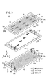
図5は、本発明の第2の実施形態に係る燃料電池スタックを構成する燃料電池80の要部分解斜視説明図である。
FIG. 5 is an exploded perspective view of a main part of a
なお、第1の実施形態に係る燃料電池22と同一の構成要素には同一の参照符号を付して、その詳細な説明は省略する。
Note that the same components as those of the
燃料電池80は、電解質膜・電極構造体82が、第1及び第2セパレータ84、86に挟持される。第1及び第2セパレータ84、86は、金属セパレータ又はカーボンセパレータで構成される。
In the
燃料電池80は、矢印B方向の一端縁部、すなわち、長方形状の一方の短辺側には、酸化剤ガス入口連通孔36a、燃料ガス入口連通孔38a及び冷却媒体入口連通孔40aが矢印C方向に配列して設けられる。
The
燃料電池80は、矢印B方向の他端縁部、すなわち、長方形状の他方の短辺側には、酸化剤ガス出口連通孔36b、燃料ガス出口連通孔38b及び冷却媒体出口連通孔40bが矢印C方向に配列して設けられる。
The
第1セパレータ84は、長方形状の各短辺側一方の角部には、切り欠き部52a、52bを介して電圧測定端子54a、54bが設けられるとともに、前記長方形状の各短辺側他方の角部には、燃料ガス入口連通孔38a及び燃料ガス出口連通孔38bが設けられる。
The
第2セパレータ86は、同様に、長方形状の各短辺側一方の角部には、切り欠き部56a、56bを介して電圧測定端子58a、58bが設けられるとともに、前記長方形状の各短辺側他方の角部には、燃料ガス入口連通孔38a及び燃料ガス出口連通孔38bが設けられる。
Similarly, the
このように構成される第2の実施形態では、燃料電池80は、長方形状を有するとともに、長方形状の短辺側一方の角部には、電圧測定端子54a、58aが設けられている。このため、燃料電池80は、幅寸法が可及的に小型化される他、電圧測定端子54a、58aが燃料ガスに影響を与えることがない等、上記の第1の実施形態と同様の効果が得られる。
In the second embodiment configured as described above, the
第1及び第2の実施形態では、電流取り出し端子として電圧測定端子54a、54bを用いて説明したが、これに限定されるものではない。
In the first and second embodiments, the
図6に示す本発明の第3の実施形態に係る燃料電池スタック100は、複数の燃料電池22又は燃料電池80(以下、単に燃料電池22という)が矢印A方向に積層されるとともに、所定数の前記燃料電池22が直列に接続された燃料電池モジュール102を構成する。なお、燃料電池モジュール102は、単一の燃料電池22であってもよい。
A
各燃料電池モジュール102の積層方向両端には、電流取り出し端子104a、104bが設けられ、前記電流取り出し端子104a、104bにバイパス回路106のコネクタ(図示せず)が接続される。
バイパス回路106には、ダイオード108が設けられる。このダイオード108は、図7に示すように、アノード側がアノード側電極64に接続されるとともに、カソード側がカソード側電極62に接続される。ダイオード108は、燃料電池モジュール102が正常である際に逆方向バイアス状態になる一方、前記燃料電池モジュール102に異常が発生した際に順方向バイアス状態になるように設定される。
The
このように構成される第3の実施形態では、燃料電池22のいずれかに故障が発生した場合、この燃料電池22を含む燃料電池モジュール102に並列接続されたダイオード108が順バイアス状態になり、前記ダイオード108に電流が流れる(図7参照)。
In the third embodiment configured as described above, when any of the
図8に示す本発明の第4の実施形態に係る燃料電池スタック110は、複数の燃料電池22が矢印A方向に積層されるとともに、所定数の前記燃料電池22が直列に接続された燃料電池モジュール112を構成する。なお、燃料電池モジュール112は、単一の燃料電池22であってもよい。
The
各燃料電池モジュール112の積層方向両端には、電流取り出し端子114a、114bが設けられ、前記電流取り出し端子114a、114bにディスチャージ回路116のコネクタ(図示せず)が接続される。
ディスチャージ回路116には、ダイオード118が設けられる。このダイオード118は、図9に示すように、アノード側がカソード側電極62に接続されるとともに、カソード側がアノード側電極64に接続される。
The
このように構成される第4の実施形態では、燃料電池スタック110の停止時に、燃料電池22内に残存するガス(特に燃料ガス)を消費させるために、ダイオード118が設けられている。従って、運転停止時には、図9に示すように、各ディスチャージ回路116内で、矢印に示すようにダイオード118に電流が流れる。これにより、燃料電池モジュール112のディスチャージが遂行され、前記燃料電池モジュール112に残存するガスが消費される。
In the fourth embodiment configured as described above, the
10、100、110…燃料電池スタック
12…燃料電池車両 14…車室
18…センターコンソール 20…電圧測定装置
22、80…燃料電池 28a、28b…エンドプレート
30、82…電解質膜・電極構造体 32、34、84、86…セパレータ
36a…酸化剤ガス入口連通孔 36b…酸化剤ガス出口連通孔
38a…燃料ガス入口連通孔 38b…燃料ガス出口連通孔
40a…冷却媒体入口連通孔 40b…冷却媒体出口連通孔
42…酸化剤ガス流路 44…燃料ガス流路
46…冷却媒体流路
52a、52b、56a、56b…切り欠き部
54a、54b、58a、58b…電圧測定端子
60…固体高分子電解質膜 62…カソード側電極
64…アノード側電極 66…連結部材
70…コネクタ 72…ケーブル
104a、104b、114a、114b…電流取り出し端子
106…バイパス回路 108、118…ダイオード
116…ディスチャージ回路
DESCRIPTION OF
Claims (4)
前記長方形状の短辺側一方の角部には、切り欠き部を設け、前記切り欠き部に膨出して外部へ電流を取り出す電流取り出し端子が設けられるとともに、
前記長方形状の短辺側他方の角部には、燃料ガスを流通させる燃料ガス連通孔が設けられることを特徴とする燃料電池スタック。 An electrolyte membrane / electrode structure provided with a pair of electrodes on both sides of the electrolyte membrane and a separator are stacked, and a fuel cell stack having a rectangular shape in plan view,
At one corner on the short side of the rectangular shape, a notch is provided, and a current takeout terminal is provided that bulges into the notch and takes out current to the outside.
A fuel cell stack, wherein a fuel gas communication hole through which fuel gas flows is provided at the other corner portion on the short side of the rectangular shape.
前記長方形状の長辺側は、前記車両の前後方向に沿って配設され、且つ、前記電流取り出し端子は、前記車両の後方側に向かって配設されることを特徴とする燃料電池スタック。 The fuel cell stack according to claim 1 or 2, wherein the fuel cell stack is mounted on a vehicle,
The long side of the rectangular shape is disposed along the front-rear direction of the vehicle, and the current extraction terminal is disposed toward the rear side of the vehicle.
Priority Applications (1)
| Application Number | Priority Date | Filing Date | Title |
|---|---|---|---|
| JP2009109452A JP5449848B2 (en) | 2009-04-28 | 2009-04-28 | Fuel cell stack |
Applications Claiming Priority (1)
| Application Number | Priority Date | Filing Date | Title |
|---|---|---|---|
| JP2009109452A JP5449848B2 (en) | 2009-04-28 | 2009-04-28 | Fuel cell stack |
Publications (3)
| Publication Number | Publication Date |
|---|---|
| JP2010257888A JP2010257888A (en) | 2010-11-11 |
| JP2010257888A5 JP2010257888A5 (en) | 2012-03-08 |
| JP5449848B2 true JP5449848B2 (en) | 2014-03-19 |
Family
ID=43318569
Family Applications (1)
| Application Number | Title | Priority Date | Filing Date |
|---|---|---|---|
| JP2009109452A Expired - Fee Related JP5449848B2 (en) | 2009-04-28 | 2009-04-28 | Fuel cell stack |
Country Status (1)
| Country | Link |
|---|---|
| JP (1) | JP5449848B2 (en) |
Families Citing this family (2)
| Publication number | Priority date | Publication date | Assignee | Title |
|---|---|---|---|---|
| JP5889744B2 (en) * | 2012-07-30 | 2016-03-22 | 本田技研工業株式会社 | Fuel cell |
| JP6158867B2 (en) * | 2015-07-29 | 2017-07-05 | 本田技研工業株式会社 | Inspection method of electrolyte membrane / electrode structure with resin frame |
Family Cites Families (2)
| Publication number | Priority date | Publication date | Assignee | Title |
|---|---|---|---|---|
| JP2006269333A (en) * | 2005-03-25 | 2006-10-05 | Nissan Motor Co Ltd | Fuel cell |
| JP4843438B2 (en) * | 2006-09-28 | 2011-12-21 | 本田技研工業株式会社 | Arrangement structure of cell voltage monitoring device for fuel cell for fuel cell vehicle |
-
2009
- 2009-04-28 JP JP2009109452A patent/JP5449848B2/en not_active Expired - Fee Related
Also Published As
| Publication number | Publication date |
|---|---|
| JP2010257888A (en) | 2010-11-11 |
Similar Documents
| Publication | Publication Date | Title |
|---|---|---|
| US9539897B2 (en) | Fuel cell vehicle | |
| JP4630529B2 (en) | Fuel cell system | |
| US20050186464A1 (en) | Fuel cell | |
| US9905878B2 (en) | Fuel cell stack and fuel cell vehicle | |
| US9450264B2 (en) | Vehicle-mounted cell stack system | |
| US9590254B2 (en) | Fuel cell stack | |
| US7846589B2 (en) | Fuel cell having separator with cell voltage terminal | |
| JP2010212024A (en) | Fuel battery | |
| JP4165876B2 (en) | Fuel cell stack | |
| JP2013152878A (en) | Fuel cell system | |
| JP6059615B2 (en) | Fuel cell stack | |
| JP5879239B2 (en) | In-vehicle fuel cell system | |
| JP2013193724A (en) | Fuel cell system | |
| JP5449848B2 (en) | Fuel cell stack | |
| JP2015170545A (en) | fuel cell stack | |
| JP6499249B1 (en) | Fuel cell stack | |
| JP2013161550A (en) | Fuel cell stack | |
| JP5011749B2 (en) | Fuel cell device | |
| JP2007207555A (en) | Fuel cell | |
| JP5378074B2 (en) | Fuel cell stack | |
| JP2015009768A (en) | Mounting structure for fuel cell stack | |
| JP5302758B2 (en) | Fuel cell stack | |
| JP5366793B2 (en) | Fuel cell system | |
| JP6104113B2 (en) | Fuel cell | |
| JP5474606B2 (en) | Automotive fuel cell stack |
Legal Events
| Date | Code | Title | Description |
|---|---|---|---|
| A521 | Request for written amendment filed |
Free format text: JAPANESE INTERMEDIATE CODE: A523 Effective date: 20120125 |
|
| A621 | Written request for application examination |
Free format text: JAPANESE INTERMEDIATE CODE: A621 Effective date: 20120125 |
|
| A977 | Report on retrieval |
Free format text: JAPANESE INTERMEDIATE CODE: A971007 Effective date: 20130523 |
|
| A131 | Notification of reasons for refusal |
Free format text: JAPANESE INTERMEDIATE CODE: A131 Effective date: 20130528 |
|
| A521 | Request for written amendment filed |
Free format text: JAPANESE INTERMEDIATE CODE: A523 Effective date: 20130724 |
|
| TRDD | Decision of grant or rejection written | ||
| A01 | Written decision to grant a patent or to grant a registration (utility model) |
Free format text: JAPANESE INTERMEDIATE CODE: A01 Effective date: 20131203 |
|
| A61 | First payment of annual fees (during grant procedure) |
Free format text: JAPANESE INTERMEDIATE CODE: A61 Effective date: 20131225 |
|
| R150 | Certificate of patent or registration of utility model |
Ref document number: 5449848 Country of ref document: JP Free format text: JAPANESE INTERMEDIATE CODE: R150 Free format text: JAPANESE INTERMEDIATE CODE: R150 |
|
| LAPS | Cancellation because of no payment of annual fees |