JP5447004B2 - Transmission device, display device, shutter glasses, transmission / reception system, display system, and transmission / reception method - Google Patents
Transmission device, display device, shutter glasses, transmission / reception system, display system, and transmission / reception method Download PDFInfo
- Publication number
- JP5447004B2 JP5447004B2 JP2010045805A JP2010045805A JP5447004B2 JP 5447004 B2 JP5447004 B2 JP 5447004B2 JP 2010045805 A JP2010045805 A JP 2010045805A JP 2010045805 A JP2010045805 A JP 2010045805A JP 5447004 B2 JP5447004 B2 JP 5447004B2
- Authority
- JP
- Japan
- Prior art keywords
- shutter
- command set
- transmission
- types
- eye
- Prior art date
- Legal status (The legal status is an assumption and is not a legal conclusion. Google has not performed a legal analysis and makes no representation as to the accuracy of the status listed.)
- Expired - Fee Related
Links
Images


Classifications
-
- H—ELECTRICITY
- H04—ELECTRIC COMMUNICATION TECHNIQUE
- H04N—PICTORIAL COMMUNICATION, e.g. TELEVISION
- H04N13/00—Stereoscopic video systems; Multi-view video systems; Details thereof
- H04N13/30—Image reproducers
-
- H—ELECTRICITY
- H04—ELECTRIC COMMUNICATION TECHNIQUE
- H04N—PICTORIAL COMMUNICATION, e.g. TELEVISION
- H04N13/00—Stereoscopic video systems; Multi-view video systems; Details thereof
- H04N13/30—Image reproducers
- H04N13/332—Displays for viewing with the aid of special glasses or head-mounted displays [HMD]
- H04N13/341—Displays for viewing with the aid of special glasses or head-mounted displays [HMD] using temporal multiplexing
-
- H—ELECTRICITY
- H04—ELECTRIC COMMUNICATION TECHNIQUE
- H04N—PICTORIAL COMMUNICATION, e.g. TELEVISION
- H04N13/00—Stereoscopic video systems; Multi-view video systems; Details thereof
-
- H—ELECTRICITY
- H04—ELECTRIC COMMUNICATION TECHNIQUE
- H04N—PICTORIAL COMMUNICATION, e.g. TELEVISION
- H04N13/00—Stereoscopic video systems; Multi-view video systems; Details thereof
- H04N13/10—Processing, recording or transmission of stereoscopic or multi-view image signals
- H04N13/106—Processing image signals
- H04N13/167—Synchronising or controlling image signals
-
- H—ELECTRICITY
- H04—ELECTRIC COMMUNICATION TECHNIQUE
- H04N—PICTORIAL COMMUNICATION, e.g. TELEVISION
- H04N13/00—Stereoscopic video systems; Multi-view video systems; Details thereof
- H04N13/20—Image signal generators
- H04N13/296—Synchronisation thereof; Control thereof
-
- H—ELECTRICITY
- H04—ELECTRIC COMMUNICATION TECHNIQUE
- H04N—PICTORIAL COMMUNICATION, e.g. TELEVISION
- H04N13/00—Stereoscopic video systems; Multi-view video systems; Details thereof
- H04N13/30—Image reproducers
- H04N13/398—Synchronisation thereof; Control thereof
-
- H—ELECTRICITY
- H04—ELECTRIC COMMUNICATION TECHNIQUE
- H04N—PICTORIAL COMMUNICATION, e.g. TELEVISION
- H04N13/00—Stereoscopic video systems; Multi-view video systems; Details thereof
- H04N2013/0074—Stereoscopic image analysis
- H04N2013/0096—Synchronisation or controlling aspects
-
- H—ELECTRICITY
- H04—ELECTRIC COMMUNICATION TECHNIQUE
- H04N—PICTORIAL COMMUNICATION, e.g. TELEVISION
- H04N2213/00—Details of stereoscopic systems
- H04N2213/008—Aspects relating to glasses for viewing stereoscopic images
Description
本発明は、シャッタ眼鏡等の受信装置を用いた送受信システムおよび表示システム、ならびにそのようなシステムに好適に用いられる送信装置、シャッタ眼鏡、表示装置および送受信方法に関する。 The present invention relates to a transmission / reception system and a display system using a receiving device such as shutter glasses, and a transmission device, shutter glasses, a display device, and a transmission / reception method suitably used for such a system.
近年、立体視表示が可能な表示システムが注目を集めている。そのような表示システムの1つに、シャッタ眼鏡を用いた表示システムがある。この表示システムでは、互いに視差がある左眼用画像と右眼用画像とが、表示装置に交互に時分割的に表示されると共に、これらの画像の切換え(表示タイミング)に同期して、シャッタ眼鏡における左眼用シャッタおよび右眼用シャッタの開閉が切換え制御される。この切換え動作を繰り返すことにより、観察者は、これらの一連の画像からなる映像を奥行きのある立体的な映像として認識することができる。 In recent years, display systems capable of stereoscopic display have attracted attention. One such display system is a display system using shutter glasses. In this display system, a left-eye image and a right-eye image that have parallax are alternately displayed on a display device in a time-division manner, and a shutter is synchronized with switching (display timing) between these images. The opening / closing of the shutter for the left eye and the shutter for the right eye in the glasses is switched. By repeating this switching operation, the observer can recognize a video composed of a series of these images as a stereoscopic video having a depth.
このようなシャッタ眼鏡における左眼用シャッタおよび右眼用シャッタの開閉制御はそれぞれ、通常、表示装置から供給されるシャッタ制御信号に基づいて行われる(例えば、非特許文献1参照)。この非特許文献1におけるシャッタ装置の制御方法では、シャッタ制御信号として、デューティ比が50%の信号を用いている。そして、シャッタ制御信号のレベル信号が高レベルのときには、表示装置に左眼用画像を表示すると共にシャッタ眼鏡の左眼用シャッタを開く一方、低レベルのときには、表示装置に右眼用画像を表示すると共にシャッタ眼鏡の右眼用シャッタを開くように制御している。
The opening / closing control of the left eye shutter and the right eye shutter in such shutter glasses is usually performed based on a shutter control signal supplied from the display device (see, for example, Non-Patent Document 1). In the control method of the shutter device in Non-Patent
ところで、上記表示システムを使用する環境下では、一般に、例えば他の電子機器の遠隔制御に用いられる無線信号(赤外線信号等)などが飛び交っていることが多い。したがって、表示システムにおいて表示装置(送信側)からシャッタ眼鏡(受信側)へと送られるシャッタ制御信号がそのような他の外部信号の影響を受け、ノイズ(外部ノイズ)を含んでしまうおそれがある。シャッタ制御信号に外部ノイズが含まれると、受信側において誤動作等を発生する要因となり、信頼性の高い通信の実現が困難となってしまう。 By the way, in an environment where the display system is used, in general, for example, radio signals (infrared signals, etc.) used for remote control of other electronic devices often fly. Therefore, the shutter control signal sent from the display device (transmission side) to the shutter glasses (reception side) in the display system may be affected by such other external signals and include noise (external noise). . If the shutter control signal includes external noise, it may cause a malfunction on the receiving side, making it difficult to realize highly reliable communication.
ところが、上記非特許文献1の手法を含め、従来のシャッタ装置の制御方法においては、そのような外部ノイズに対する対策がなされていないか、あるいは不十分であったため、通信の際の信頼性を向上させることが可能な手法の提案が望まれていた。
However, in the conventional shutter device control method including the method of Non-Patent
本発明はかかる問題点に鑑みてなされたもので、その目的は、送信側と受信側との間で信頼性の高い通信を実現することが可能な送信装置、表示装置、シャッタ眼鏡、送受信システム、表示システムおよび送受信方法を提供することにある。 The present invention has been made in view of such problems, and a purpose thereof is a transmission device, a display device, shutter glasses, and a transmission / reception system capable of realizing highly reliable communication between a transmission side and a reception side. It is to provide a display system and a transmission / reception method.
本発明の送信装置は、複数のビットにより表現されたコマンドを複数種類保持すると共に、これらの複数種類のコマンドから選択される複数種類のコマンドを所定の順番で組み合わせてなるコマンドセットを繰り返し送信する送信部を備えたものである。このコマンドセットに含まれる各コマンドは、同期制御信号に基づく異なるタイミングで送信され、コマンドセット全体としてのビットパターンは、受信装置側において保持されているビットパターンと比較されるようになっている。 The transmission apparatus according to the present invention holds a plurality of types of commands expressed by a plurality of bits, and repeatedly transmits a command set formed by combining a plurality of types of commands selected from the plurality of types of commands in a predetermined order. A transmission unit is provided. Each command included in this command set is transmitted at different timings based on the synchronization control signal, and the bit pattern of the entire command set is compared with the bit pattern held on the receiving device side.
本発明の表示装置は、複数種類の画像ストリームを順次切り換えて表示する表示部と、複数種類の画像ストリームの切り換えタイミングと同期した開閉動作を行うシャッタ眼鏡に対し、複数のビットにより表現されたシャッタ制御コマンドを送信する送信部とを備えたものである。この送信部は、シャッタ制御コマンドを複数種類保持すると共に、これらの複数種類のシャッタ制御コマンドから選択される複数種類のシャッタ制御コマンドを所定の順番で組み合わせてなるコマンドセットを繰り返し送信するようになっている。上記コマンドセットに含まれる各シャッタ制御コマンドは、同期制御信号に基づく異なるタイミングで送信され、このコマンドセット全体としてのビットパターンは、シャッタ眼鏡側において保持されているビットパターンと比較されるようになっている。 Display device of the present invention includes a display unit displaying sequentially switches a plurality of types of image streams, the plurality kinds of image streams shutter glasses performing an opening and closing operation in synchronization with switching timing of, expressed by a plurality of bits And a transmission unit that transmits a shutter control command. The transmission unit holds a plurality of types of shutter control commands and repeatedly transmits a command set formed by combining a plurality of types of shutter control commands selected from the plurality of types of shutter control commands in a predetermined order. ing. Each shutter control command included in the command set is transmitted at a different timing based on the synchronization control signal, and the bit pattern of the entire command set is compared with the bit pattern held on the shutter glasses side. ing.
本発明のシャッタ眼鏡は、複数のビットにより表現されたシャッタ制御コマンドを複数種類保持すると共にこれらの複数種類のシャッタ制御コマンドから選択される複数種類のシャッタ制御コマンドを所定の順番で組み合わせてなるコマンドセットを繰り返し送信する表示装置から、各シャッタ制御コマンドが同期制御信号に基づく異なるタイミングで送信されてなるコマンドセットを受信する受信部と、受信されたコマンドセットに基づいて、表示装置において順次切り換えて表示される複数種類の画像ストリームの切り換えタイミングと同期した開閉動作を行う左眼用シャッタおよび右眼用シャッタと、所定のビットパターンを保持する保持部とを備えたものである。上記コマンドセット全体としてのビットパターンは、保持部において保持されているビットパターンと比較されるようになっている。 The shutter glasses of the present invention hold a plurality of types of shutter control commands expressed by a plurality of bits, and combine a plurality of types of shutter control commands selected from the plurality of types of shutter control commands in a predetermined order. A receiving unit that receives a command set in which each shutter control command is transmitted at different timings based on a synchronization control signal from a display device that repeatedly transmits the set, and the display device sequentially switches based on the received command set. The shutter includes a left-eye shutter and a right-eye shutter that perform an opening / closing operation in synchronization with a switching timing of a plurality of types of displayed image streams, and a holding unit that holds a predetermined bit pattern. The bit pattern of the entire command set is compared with the bit pattern held in the holding unit.
本発明の送受信システムは、上記本発明の送信装置と、上記本発明のシャッタ眼鏡とを備えたものである。 The transmission / reception system of the present invention includes the transmission device of the present invention and the shutter glasses of the present invention.
本発明の表示システムは、上記本発明の表示装置と、上記本発明のシャッタ眼鏡とを備えたものである。 The display system of the present invention includes the display device of the present invention and the shutter glasses of the present invention.
本発明の送受信方法は、送信装置において、各々が複数のビットにより表現された複数種類のシャッタ制御コマンドから選択される複数種類のシャッタ制御コマンドを所定の順番で組み合わせてなるコマンドセットを、そのコマンドセットに含まれる各シャッタ制御コマンドが同期制御信号に基づく異なるタイミングで送信されるように生成すると共に、このコマンドセットをシャッタ眼鏡に対して繰り返し送信し、シャッタ眼鏡において、上記コマンドセットを受信し、受信したコマンドセットに基づいて、そのコマンドセット全体としてのビットパターンとこのシャッタ眼鏡において保持されているビットパターンとを比較すると共に、左眼用シャッタおよび右眼用シャッタがそれぞれ、複数種類の画像ストリームを順次切り換えて表示する表示装置における複数種類の画像ストリームの切り換えタイミングと同期した開閉動作を行うようにしたものである。 Transmission and reception method of the present invention, a transmitting apparatus, a command set, each comprising a combination of a plurality of types of shutter control command selected from a plurality of multiple types expressed by the bit of the shutter control commands in a predetermined order, the command with each shutter control commands in the set is generated so as to be transmitted at different timings based on the synchronization control signal, the command set and repeatedly transmitted to the shutter glasses, in sheets Yatta glasses, receiving the command set Based on the received command set, the bit pattern of the entire command set is compared with the bit pattern held in the shutter glasses, and the left-eye shutter and the right-eye shutter each have a plurality of types of images. Display by sequentially switching streams It is obtained so as to synchronize the opening and closing operation with the switching timing of a plurality of types of image streams on the display device that.
本発明の送信装置、表示装置、シャッタ眼鏡、送受信システム、表示システムおよび送受信方法では、複数種類のコマンド(またはシャッタ制御コマンド)から選択される複数種類のコマンドが所定の順番で組み合わされてなり、送信装置(または送信部)から繰り返し送信されるコマンドセットにおいて、このコマンドセット全体としてのビットパターンが、受信装置(またはシャッタ眼鏡)側において保持されているビットパターンと比較される。これにより、送信側から受信側へとコマンドセットを含む信号の通信を行う際に、受信側において、そのコマンドセットが外部ノイズを含んでいるか否かの判別が容易となる。 Transmitting device, a display device of the present invention, the shutter glasses, the transmitting and receiving system, a display system and reception method, a plurality of types of commands to be selected from a plurality of kinds of commands (or the shutter control command) is combined in a predetermined order, In the command set repeatedly transmitted from the transmission device (or transmission unit), the bit pattern as the entire command set is compared with the bit pattern held on the reception device (or shutter glasses) side. Thereby, when communication of a signal including a command set is performed from the transmission side to the reception side, it is easy to determine whether or not the command set includes external noise on the reception side.
本発明の送信装置、表示装置、シャッタ眼鏡、送受信システム、表示システムおよび送受信方法によれば、送信装置(または送信部)から繰り返し送信されるコマンドセット全体としてのビットパターンが、受信装置(またはシャッタ眼鏡)側において保持されているビットパターンと比較されるようにしたので、送信側から受信側へとコマンドセットを含む信号の通信を行う際に、そのコマンドセットが外部ノイズを含んでいるか否かを受信側で容易に判別することができる。よって、そのような外部ノイズの影響を低減もしくは回避し易くなり、送信側と受信側との間で信頼性の高い通信を実現することが可能となる。 According to the transmission device, the display device, the shutter glasses, the transmission / reception system, the display system, and the transmission / reception method of the present invention, the bit pattern as the entire command set that is repeatedly transmitted from the transmission device (or transmission unit) since as compared with the bit pattern held in the spectacles) side, when communicating signals including the command set to the receiving side from the transmitting side, whether the command set includes external noises Can be easily discriminated on the receiving side. Therefore, it becomes easy to reduce or avoid the influence of such external noise, and it is possible to realize highly reliable communication between the transmission side and the reception side.
以下、本発明の実施の形態について、図面を参照して詳細に説明する。なお、説明は以下の順序で行う。
実施の形態(送信装置が表示装置に内蔵されてなる立体視表示システムの例)
変形例
変形例1(送信装置が表示装置の外部に設けられてなる立体視表示システムの例)
変形例2(マルチビューシステムの例)
Hereinafter, embodiments of the present invention will be described in detail with reference to the drawings. The description will be given in the following order.
Embodiment (Example of stereoscopic display system in which transmission device is built in display device)
Modified example Modified example 1 (an example of a stereoscopic display system in which a transmission device is provided outside a display device)
Modification 2 (example of multi-view system)
<実施の形態>
[表示システム1の全体構成]
図1は、本発明の一実施の形態に係る表示システム(表示システム1)の全体構成を表すものである。この表示システム1は、互いに視差を有する左眼用画像と右眼用画像とを交互に時分割的に表示すると共に、これらの左眼用画像および右眼用画像の切換え(表示タイミング)に同期してシャッタ眼鏡の左右のシャッタの開閉を切換え制御することにより、立体視表示を行う立体視表示システムである。表示システム1は、本発明の一実施の形態に係る表示装置としての表示装置10と、本発明の一実施の形態に係るシャッタ眼鏡(受信装置)としてのシャッタ眼鏡60とを備えている。
<Embodiment>
[Overall configuration of display system 1]
FIG. 1 shows the overall configuration of a display system (display system 1) according to an embodiment of the present invention. The
[表示装置10の詳細構成]
表示装置10は、信号処理部20、表示駆動部11、表示部12、音声増幅部13、スピーカ14およびシャッタ制御部15を有している。この表示装置10は、立体視用映像信号を含む入力信号Dinに基づいて、表示部12に映像を表示すると共にスピーカ14から音声を出力するものである。ここで、立体視用映像信号とは、互いに視差を有する左眼用画像と右眼用画像とを時間軸に沿った交互に配列してなる映像信号のことである。なお、シャッタ制御部15が、本発明における「送信装置」および「送信部」の一具体例に対応している。
[Detailed Configuration of Display Device 10]
The
(信号処理部20)
信号処理部20は、入力信号Dinに基づいて、左眼用画像信号と右眼用画像信号とを含む映像信号D1と、音声信号D2とを生成するものである。この信号処理部20はまた、シャッタ制御部15を制御するための信号を生成し出力する機能も有している。具体的には、詳細は後述するが、信号処理部20における映像信号処理回路23(後述)は、左眼用画像信号と右眼用画像信号とに同期した同期制御信号Syncを出力し、シャッタ制御部15に供給するようになっている。
(Signal processing unit 20)
The
信号処理部20は、図2に示したように、デジタルチューナ21、MPEG(Moving Picture Experts Group)デコーダ22、映像信号処理回路23、グラフィック生成回路24、音声信号処理回路25、HDMI(High-Definition Multimedia Interface)レシーバ26およびネットワークインターフェース27を有している。
As shown in FIG. 2, the
デジタルチューナ21は、アンテナ(図示せず)において受信されアンテナ端子TAを介して供給された放送波(図1における入力信号Dinに対応)から、所望の信号(ストリーム)を選択するものである。MPEGデコーダ22は、デジタルチューナ21において選択されたストリームから映像信号と音声信号とを抽出するものである。
The
映像信号処理回路23は、MPEGデコーダ22において抽出された映像信号に対して、ガンマ処理、YUV−RGB変換、フレーム順次出力などの映像信号処理を施すと共に、同期制御信号Syncを生成する機能を有している。なお、この同期制御信号Syncの生成動作の詳細については後述する。
The video
グラフィック生成回路24は、OSD(On Screen Display)情報を生成すると共に映像信号処理回路23から供給された映像に対して重畳させ、その出力信号を映像信号D1として表示駆動部11に供給するものである。音声信号処理回路25は、MPEGデコーダ22において抽出された音声信号に対して、サラウンド処理などの音声信号処理を施し、その出力信号を音声信号D2として音声増幅部13に供給するものである。
The
ここで、図2に示した表示装置10では、上述した放送波の他、複数の信号を入力信号Dinとして選択できるようになっている。具体的には、以下に示すように、例えばBD(Blu-ray Disk)レコーダなどの外部機器からの信号や、IP(Internet Protocol)放送信号などを入力信号Dinとして選択することができるようになっている。
Here, in the
HDMIレシーバ26は、外部機器(図示せず)からHDMI端子THを介して供給された信号を受信する回路である。このHDMIレシーバ26は、その受信した信号から映像信号と音声信号とを抽出し、映像信号を映像信号処理回路23に供給すると共に、音声信号を音声信号処理回路25へ供給する機能を有している。
The
ネットワークインターフェース27は、インターネットに接続されたネットワーク端子TNを介して供給されたIP放送信号を受信し、その受信した信号をMPEGデコーダ22に供給するものである。
The
なお、信号処理部20は、内部バス31により互いに接続された、メモリ32、フラッシュROM33およびCPU34を更に有している。この内部バス31は、ネットワークインターフェース27と接続されている。信号処理部20はまた、リモコン受信部35を有している。このリモコン受信部35は、外部のリモコン(図示せず)からの指示信号であるリモコン信号RS(例えば赤外線信号)を受信し、CPU34へ供給するようになっている。
The
(表示駆動部11・表示部12)
図1において、表示駆動部11は、信号処理部20から供給された映像信号D1に基づいて、表示部12を駆動するための駆動信号を生成する回路である。表示部12は、この表示駆動部11から供給される駆動信号に基づき、左眼用画像と右眼用画像とを交互に表示するようになっている。
(
In FIG. 1, the
ここで、図3および図4を参照して、表示駆動部11および表示部12の一構成例について説明する。図3は、表示駆動部11および表示部12の一構成例を表すものである。図3に示したように、表示部12は、液晶表示デバイス45およびバックライト46を有している。また、表示駆動部11は、タイミング制御部41、ゲートドライバ42、データドライバ43およびバックライト駆動部44を有している。
Here, with reference to FIG. 3 and FIG. 4, one structural example of the
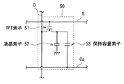
液晶表示デバイス45は、データドライバ43から供給される画素信号に基づいて画像表示を行うものである。この液晶表示デバイス45では、画素50がマトリクス状に配列されている。
The liquid
各画素50は、図4に示したように、TFT(Thin Film Transistor)素子51、液晶素子52および保持容量素子53を有している。TFT素子51は、例えばMOS−FET(Metal Oxide Semiconductor-Field Effect Transistor)により構成されている。このTFT素子51は、ゲートがゲート線Gに接続され、ソースがデータ線Dに接続され、ドレインが液晶素子52の一端および保持容量素子53の一端にそれぞれ接続されている。液晶素子52は、一端がTFT素子51のドレインに接続され、他端は接地されている。保持容量素子53は、一端がTFT素子51のドレインに接続され、他端は保持容量線Csに接続されている。なお、ゲート線Gはゲートドライバ42に接続され、データ線Dはデータドライバ43に接続されている。
As shown in FIG. 4, each
バックライト46は、液晶表示デバイス45に対して光を照射する光源であり、例えばLED(Light Emitting Diode)やCCFL(Cold Cathode Fluorescent Lamp)等を用いて構成されている。
The backlight 46 is a light source that irradiates the liquid
タイミング制御部41は、ゲートドライバ42、データドライバ43およびバックライト駆動部44の駆動タイミングを制御すると共に、信号処理部20から供給された映像信号D1をデータドライバ42へ供給するものである。ゲートドライバ42は、タイミング制御部41によるタイミング制御に従って、液晶表示デバイス45内の画素50を列ごとに選択して、線順次走査するものである。データドライバ43は、液晶表示デバイス45の各画素50へ、映像信号D1に基づく画素信号を供給するものである。具体的には、映像信号D1に対してD/A(デジタル/アナログ)変換を施すことにより、アナログ信号である画素信号を生成し、各画素50へ供給するようになっている。バックライト駆動部44は、タイミング制御部41によるタイミング制御に従って、バックライト46の点灯動作を制御するものである。
The
このような構成により、表示部12では、ゲートドライバ42により選択された画素50に対して、データドライバ43から画素信号が供給される。その結果、バックライト46からの光が、その画素50の液晶素子52により変調される。これらの動作が、液晶表示デバイス45の表示面に対して線順次走査により行われることにより、画像が表示される。表示部12は、交互に供給される左眼用画像信号および右眼用画像信号のそれぞれに対してこのような表示動作を行うことにより、左眼用画像と右眼用画像とを交互に時分割表示するようになっている。
With this configuration, in the
(音声増幅部13・スピーカ14)
図1において、音声増幅部13は、信号処理部20から供給された音声信号D2を増幅するものである。また、スピーカ14は、音声増幅部13において増幅された音声信号を出力するものである。
(
In FIG. 1, the
(シャッタ制御部15)
シャッタ制御部15は、信号処理部20から供給された同期制御信号Syncに基づいてシャッタ制御信号CTLを生成し、例えば赤外線や電波などを用いた無線通信によりシャッタ眼鏡60へ供給するものである。このシャッタ制御信号CTLは、シャッタ眼鏡60の開閉動作を制御する為のコード化された信号であると共に、後述するコマンドセットCSを含む信号であり、表示装置10に表示される左眼用画像および右眼用画像に同期した信号となっている。ここで、コマンドセットCSとは、複数種類のシャッタ制御コマンドCMDから選択される1種以上(ここでは2種以上)のシャッタ制御コマンドCMDを、所定の順番で組み合わせてなるものである。なお、詳細は後述するが、シャッタ制御部15は、立体映像を視認する際のクロストーク現象(映像の混ざりこみ)やフリッカー(映像のちらつき)を抑えること等を目的として、複数の送信モードでの送信を行うように構成されている。そして、これらの複数の送信モードごとに、異なるコマンドセットCSが用意されるようになっている。
(Shutter controller 15)
The
このシャッタ制御部15は、図2に示したように、シャッタ制御信号生成部151、ビットパターン保持部152および送信部153を有している。
As shown in FIG. 2, the
ビットパターン保持部152は、後述する複数のビットにより表現されたシャッタ制御コマンドCMDを複数種類保持するものである。具体的には、複数種類のシャッタ制御コマンドCMDごとのビットパターン、および上記した複数の送信モードごとのシャッタ制御コマンドCMDの送信順序(コマンドセットCS全体としてのビットパターン)を保持している。
The bit
シャッタ制御信号生成部151は、同期制御信号Syncに基づいてシャッタ制御信号CTLを生成し、送信部153へ供給するものである。具体的には、まず、同期制御信号Syncのデューティに基づいて、複数の送信モードから一の送信モードを選択する。そして、ビットパターン保持部152に保持されている複数種類のシャッタ制御コマンドCMDを用いて、選択した送信モード用に用意されているコマンドセットCSを含むシャッタ制御信号CTLを生成するようになっている。なお、このようなシャッタ制御信号(コマンドセットCS)の生成動作の詳細については後述する。
The shutter control
送信部153は、例えば赤外線や電波などを用いた無線通信によりシャッタ制御信号CTLを送信し、シャッタ眼鏡60に供給するものである。具体的には、シャッタ制御信号生成部151により生成されたコマンドセットCSを、繰り返し送信するようになっている。なお、この例では、送信部153は、シャッタ制御信号CTLを無線通信により伝送するものとしているが、有線通信により伝送するようにしてもよい。
The transmission unit 153 transmits the shutter control signal CTL by wireless communication using, for example, infrared rays or radio waves, and supplies the shutter control signal CTL to the
この際、送信部153は、既存の電子機器(例えば、図示しないリモコンなど)の遠隔制御に用いられる赤外光の波長とは異なる波長の赤外光、もしくは、その遠隔制御に用いられる副搬送波周波数とは異なる副搬送波周波数、または、その双方を用いて、シャッタ制御信号CTLを送信するようにするのが望ましい。具体的には、例えばリモコンの遠隔制御に用いられる赤外光では、一般に、波長が940nm程度、副搬送波周波数が40kHz程度であることから、シャッタ制御信号CTLに用いる赤外光として、一例として、波長が850nm程度、副搬送波周波数が25kHz程度であるものを用いることが可能である。これにより、シャッタ制御信号CTLと、上記した既存の電子機器に対する遠隔制御信号(例えば、図2中に示したリモコン信号RS)との間の干渉を避けることができ、シャッタ制御信号CTL内に外部ノイズが含まれることを低減もしくは回避することができる。 At this time, the transmission unit 153 transmits infrared light having a wavelength different from the wavelength of infrared light used for remote control of an existing electronic device (for example, a remote controller (not shown)) or a subcarrier used for the remote control. It is desirable to transmit the shutter control signal CTL using a subcarrier frequency different from the frequency, or both. Specifically, for example, infrared light used for remote control of a remote control generally has a wavelength of about 940 nm and a subcarrier frequency of about 40 kHz, so as an example of infrared light used for the shutter control signal CTL, Those having a wavelength of about 850 nm and a subcarrier frequency of about 25 kHz can be used. Thereby, it is possible to avoid interference between the shutter control signal CTL and the remote control signal (for example, the remote control signal RS shown in FIG. 2) for the above-described existing electronic device. Inclusion of noise can be reduced or avoided.
[シャッタ眼鏡60の詳細構成]
シャッタ眼鏡60は、表示装置10の観察者(図示せず)が用いることにより、立体視を可能とするものである。このシャッタ眼鏡60は、図1に示したように、左眼用シャッタ6Lおよび右眼用シャッタ6Rを有している。これらの左眼用シャッタ6Lおよび右眼用シャッタ6Rにおける遮光状態(開状態および閉状態)は、シャッタ制御部15から供給されるシャッタ制御信号CTLにより制御されるようになっている。
[Detailed Configuration of Shutter Glasses 60]
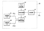
The
図5は、シャッタ眼鏡60の詳細構成例を表すものである。シャッタ眼鏡60は、受信部61、判別回路62(判別部)、ビットパターン保持部63(保持部)、シャッタ駆動回路64(駆動部)、左眼用シャッタ6Lおよび右眼用シャッタ6Rを有している。
FIG. 5 illustrates a detailed configuration example of the
受信部61は、表示装置10内の送信部29より無線通信により供給されたシャッタ制御信号CTLを受信するものである。すなわち、受信部61は、前述したコマンドセットCSを繰り返し送信する表示装置10内の送信部29から、そのコマンドセットCSを受信するようになっている。
The
ビットパターン保持部63は、受信部61において受信すると予想(想定)されるコマンドセットCS全体で形成されるビットパターンと、同一のビットパターンを保持するものである。言い換えると、ビットパターン保持部63は、シャッタ制御部15内のビットパターン保持部152と同一のビットパターンを予め保持している。すなわち、シャッタ制御コマンドCMDを複数種類保持しており、複数種類のシャッタ制御コマンドCMDごとのビットパターン、および前述した複数の送信モードごとのシャッタ制御コマンドCMDの送信順序(コマンドセットCS全体としてのビットパターン)を保持している。
The bit
判別回路62は、受信部61において受信したシャッタ制御信号CTLの制御コード(コマンドセットCS全体のビットパターン)を解読し、左眼用シャッタ6Lおよび右眼用シャッタ6Rへの開閉指示を判別するものである。具体的には、受信したコマンドセットCS全体におけるビットパターンと、ビットパターン保持部63において保持されている、対応する送信モードにおけるビットパターンとの同一性を判別するようになっている。
The discriminating
シャッタ駆動回路64は、判別回路62から供給された信号(判別結果を示す信号)に基づいて、左眼用シャッタ6Lおよび右眼用シャッタ6Rに対して、それらの開閉動作の駆動を行う回路である。具体的には、左眼用シャッタ6Lに対する左眼用シャッタ制御信号CTLLを生成して左眼用シャッタ6Lに供給すると共に、右眼用シャッタ6Rに対する右眼用シャッタ制御信号CTLRを生成して右眼用シャッタ6Rに供給するようになっている。
The
左眼用シャッタ6Lは、シャッタ駆動回路63から供給された左眼用シャッタ制御信号CTLLに基づいて、シャッタの開閉動作を行うものである。右眼用シャッタ6Rは、シャッタ駆動回路63から供給された右眼用シャッタ制御信号CTLRに基づいて、シャッタの開閉動作を行うものである。これらの左眼用シャッタ6Lおよび右眼用シャッタ6Rはそれぞれ、例えば液晶シャッタなどの遮光シャッタにより構成されている。
The left-
[シャッタ制御信号CTLの詳細構成]
次に、図6を参照して、シャッタ制御信号CTLの詳細構成について説明する。図6は、シャッタ制御信号CTLに含まれるシャッタ制御コマンドCMDの一構成例を表すものである。図6において、(A)はシャッタ制御コマンドCMDの全体構成例を示し、(B)はシャッタ制御コマンドCMDの内容とコマンドビットCBのビットパターンとの関係を規定するコマンドテーブルCTの一例を示し、(C)はシャッタ制御コマンドCMDのタイミング波形(パルス波形)の一例を示す。
[Detailed Configuration of Shutter Control Signal CTL]
Next, the detailed configuration of the shutter control signal CTL will be described with reference to FIG. FIG. 6 shows a configuration example of the shutter control command CMD included in the shutter control signal CTL. 6A shows an example of the overall configuration of the shutter control command CMD, FIG. 6B shows an example of a command table CT that defines the relationship between the content of the shutter control command CMD and the bit pattern of the command bits CB, (C) shows an example of the timing waveform (pulse waveform) of the shutter control command CMD.
シャッタ制御コマンドCMDは、例えば図6(A)に示したように、1ビットからなるスタートビットSBと、4ビットからなるコマンドビットCB(上位ビット側から下位ビット側へと順に、CB4〜CB1)とを含んでいる。 For example, as shown in FIG. 6A, the shutter control command CMD includes a 1-bit start bit SB and a 4-bit command bit CB (CB4 to CB1 in order from the upper bit side to the lower bit side). Including.
スタートビットSBは、シャッタ制御信号コマンドCMDにおける制御コードのプリアンブルとして機能するものであり、所定のビットにより構成されている。なお、シャッタ眼鏡60における判別回路62は、このスタートビットSBを検出して、コマンドビットCBの検出を行うようになっている。
The start bit SB functions as a control code preamble in the shutter control signal command CMD, and is composed of predetermined bits. The
(コマンドビットCB)
コマンドビットCBは、例えば図6(B)中に示したコマンドテーブルCTにおける各制御コマンドCMDの内容(「A」〜「F」)のように、複数種類(ここでは6種類)の制御コマンドCMDの具体的な内容を規定するためのものである。言い換えると、コマンドビットCBは、シャッタ眼鏡60における左眼用シャッタ6Lもしくは右眼用シャッタ6Rまたはその双方の開閉駆動を指示するためのものである。
(Command bit CB)
The command bit CB includes a plurality of types (six types here) of control commands CMD, such as the contents (“A” to “F”) of each control command CMD in the command table CT shown in FIG. It is for prescribing the concrete contents of. In other words, the command bit CB is for instructing to open / close the
具体的には、ここでは、コマンドビットCBが「1000」(CB4=「1」,CB3=「0」,CB2=「0」,CB1=「0」)のとき、シャッタ制御コマンドCMDの内容(「A」)は、左眼用シャッタ6Lの閉動作(「L−Close」)を指示するものとなっている。同様に、コマンドビットCBが「0100」のとき、シャッタ制御コマンドCMDの内容(「B」)は、左眼用シャッタ6Lの開動作(「L−Open」)を指示するものとなっている。コマンドビットCBが「0010」のとき、シャッタ制御コマンドCMDの内容(「C」)は、右眼用シャッタ6Rの閉動作(「R−Close」)を指示するものとなっている。コマンドビットCBが「0001」のとき、シャッタ制御コマンドCMDの内容(「D」)は、右眼用シャッタ6Rの開動作(「R−Open」)を指示するものとなっている。また、コマンドビットCBが「1010」のとき、シャッタ制御コマンドCMDの内容(「E」)は、左眼用シャッタ6Lの開動作および右眼用シャッタ6Rの閉動作(「L−Open/R−Close」)をそれぞれ指示するものとなっている。同様に、コマンドビットCBが「0101」のとき、シャッタ制御コマンドCMDの内容(「F」)は、右眼用シャッタ6Rの開動作および左眼用シャッタ6Lの閉動作(「R−Open/L−Close」)をそれぞれ指示するものとなっている。すなわち、シャッタ制御コマンドCMDの内容が「E」,「F」のときは、左眼用シャッタ6Lの動作および右眼用シャッタ6Rの動作をまとめて指示するもの(複合コマンド)となっている。なお、ここでは、コマンドビットCBにおけるその他のビットパターンについては使用されないようになっている。
Specifically, here, when the command bit CB is “1000” (CB4 = “1”, CB3 = “0”, CB2 = “0”, CB1 = “0”), the content of the shutter control command CMD ( "A") instructs to close the left-
このような構成からなるシャッタ制御コマンドCMDは、具体的には例えば図6(C)に示したようなタイミング波形(パルス波形)となっている(シャッタ制御コマンドCMDの内容が「B」のときの例)。すなわち、ここではスタートビットSBは3パルスで構成されると共に、コマンドビットCBにおける各ビットCB4〜CB1はそれぞれ、2パルスで構成されている。なお、図中のTb1,Tb2はそれぞれ、スタートビットSBとコマンドビットCBとの間のブランク期間Tb1、およびコマンドビットCBと次のシャッタ制御コマンドCMDとの間のブランク期間Tb2を示している。 Specifically, the shutter control command CMD having such a configuration has a timing waveform (pulse waveform) as shown in FIG. 6C (when the content of the shutter control command CMD is “B”). Example). That is, here, the start bit SB is composed of three pulses, and each of the bits CB4 to CB1 in the command bit CB is composed of two pulses. In the figure, Tb1 and Tb2 indicate a blank period Tb1 between the start bit SB and the command bit CB, and a blank period Tb2 between the command bit CB and the next shutter control command CMD, respectively.
[表示システムの作用・効果]
続いて、本実施の形態の表示システム1の作用および効果について説明する。
[Operation and effect of display system]
Then, an effect | action and effect of the
(1.全体動作の概要)
信号処理部20は、互いに視差を有する左眼用画像と右眼用画像とを交互に配列してなる立体視用映像信号を含む入力信号Dinに基づいて、映像信号D1および音声信号D2を生成する。具体的には、信号処理部20のデジタルチューナ21は、アンテナにおいて受信されアンテナ端子TAを介して供給された放送波(入力信号Din)から、所望の信号(ストリーム)を選択する。MPEGデコーダ22は、デジタルチューナ21において選択されたストリームから、映像信号および音声信号を抽出する。映像信号処理回路23は、MPEGデコーダ22において抽出された映像信号に対して映像信号処理を行うと共に、同期制御信号Syncを生成する。グラフィック生成回路24は、OSD情報を生成し、映像信号処理回路23から供給された映像に重畳させ、映像信号D1を生成する。音声信号処理回路25は、MPEGデコーダ22において抽出された音声信号に対して音声信号処理を行い、音声信号D2を生成する。表示駆動部11は、映像信号D1に基づいて表示部12を駆動する。表示部12は、表示駆動部11から供給される信号に基づいて、左眼用画像と右眼用画像とを交互に表示する。音声増幅部13は、音声信号D2を増幅し、スピーカ14を駆動する。スピーカ14は、音声信号を音声として出力する。
(1. Overview of overall operation)
The
シャッタ制御部15は、映像信号処理回路23から供給された同期制御信号Syncに基づいて、表示装置10における左眼用画像および右眼用画像の表示に同期したシャッタ制御信号CTLを生成し、無線通信によりシャッタ眼鏡60に供給する。
Based on the synchronization control signal Sync supplied from the video
シャッタ眼鏡60の受信部61は、シャッタ制御部15より無線通信により供給されたシャッタ制御信号CTLを受信する。判別回路62は、受信部61において受信したシャッタ制御信号CTLの制御コード(コマンドセットCS全体のビットパターン)を解読し、左眼用シャッタ6Lおよび右眼用シャッタ6Rへの開閉指示を判別する。具体的には、受信したコマンドセットCS全体におけるビットパターンと、ビットパターン保持部63において保持されている、対応する送信モードにおけるビットパターンとの同一性を判別する。シャッタ駆動回路64は、判別回路62から供給された信号(判別結果を示す信号)に基づいて、左眼用シャッタ制御信号CTLLを生成して左眼用シャッタ6Lに供給すると共に、右眼用シャッタ制御信号CTLRを生成して右眼用シャッタ6Rに供給する。左眼用シャッタ6Lは、左眼用シャッタ制御信号CTLLに基づいてシャッタの開閉動作を行い、右眼用シャッタ6Rは、右眼用シャッタ制御信号CTLRに基づいてシャッタの開閉動作を行う。
The receiving
図7は、表示システム1の全体動作を模式的に表すものである。図7において、(A)は左眼用画像Lを表示したとき(表示光LLが出射されているとき)の動作を示し、(B)は右眼用画像Rを表示したとき(表示光LRが出射されているとき)の動作を示す。
FIG. 7 schematically shows the overall operation of the
表示装置10が左眼用画像Lを表示しているとき、シャッタ眼鏡60では、図7(A)に示したように、左眼用シャッタ6Lが開状態となると共に、右眼用シャッタ6Rが閉状態となる。このとき、観察者9は左眼9Lで左眼用画像Lを見ることになる。一方、表示装置10が右眼用画像Rを表示しているとき、シャッタ眼鏡60では、図7(B)に示したように、左眼用シャッタ6Lが閉状態となると共に、右眼用シャッタ6Rが開状態となる。このとき、観察者9は右眼9Rで右眼用画像Rを見ることになる。これらの動作が交互に繰り返されると、左眼用画像Lと右眼用画像Rとの間には視差があるため、観察者9は、これらの一連の画像からなる映像を奥行きのある立体的な映像として認識することができる。
When the
(2.シャッタ制御信号CTLの生成・送受信動作)
次に、図8〜図13等を参照して、信号処理部20およびシャッタ制御部15によるシャッタ制御信号CTLの生成、ならびにシャッタ制御部15およびシャッタ眼鏡60によるシャッタ制御信号CTLの送受信動作について、詳細に説明する。
(2. Generation / transmission / reception operation of shutter control signal CTL)
Next, referring to FIGS. 8 to 13 and the like, the generation of the shutter control signal CTL by the
(2−1.信号処理部20による同期制御信号Syncの生成動作)
まず、信号処理部20内の映像信号処理回路23は、例えば、映像信号(左眼用映像信号および右眼用映像信号)の内容や切り換えタイミング、ユーザからのリモコン信号RSを介した指示内容等に基づいて、同期制御信号Syncを生成する。
(2-1. Generation of synchronization control signal Sync by the signal processing unit 20)
First, a video
図8は、このようにして生成される同期制御信号Syncと、前述したシャッタ制御信号CTLにおける送信モード等との関係の一例を表すものである。 FIG. 8 shows an example of the relationship between the synchronization control signal Sync generated in this way and the transmission mode in the shutter control signal CTL described above.
図8(A)に示したように、同期制御信号Syncは2値論理により表現される信号となっている。具体的には、この同期制御信号Syncでは、その1周期期間(例えば、100ms〜4ms程度)の前半に、論理値状態が「H(ハイ)」であるH期間THが設けられると共に、後半に論理値状態が「L(ロー)」であるL期間TLが設けられている。ただし、同期制御信号Syncのデューティ(TH/Tsync)(%)は、以下説明するように、基本的に0%〜100%の間の任意の値を取り得るものとなっている(例えば、図8(A)に示した例では、デューティ=約48%)。また、この同期制御信号Syncのデューティ(TH/Tsync)は、基本的に、左眼用シャッタ6Lおよび右眼用シャッタ6Rの各相対的開放期間長(Open期間長)を示す開放デューティDuty(%)を規定するものとなっている。
As shown in FIG. 8A, the synchronization control signal Sync is a signal expressed by binary logic. Specifically, in this synchronization control signal Sync, an H period TH in which the logical value state is “H (high)” is provided in the first half of one cycle period (for example, about 100 ms to 4 ms), and in the second half. An L period TL in which the logical value state is “L (low)” is provided. However, the duty (TH / Tsync) (%) of the synchronization control signal Sync can basically take any value between 0% and 100% as described below (for example, FIG. In the example shown in FIG. 8A, duty is about 48%). The duty (TH / Tsync) of the synchronization control signal Sync is basically an open duty Duty (%) indicating the relative open period length (Open period length) of the left-
また、例えば図8(B)に示したように、この同期制御信号Syncのデューティ(TH/Tsync)(%)の大きさ(上記した左眼用シャッタ6Lおよび右眼用シャッタ6Rの開放デューティDuty(%)の大きさ)に応じて、シャッタ制御信号CTLにおける送信モード等が決定されるようになっている。すなわち、複数の送信モードはそれぞれ、開放デューティDuty(%)の範囲(同期制御信号Syncのデューティ(TH/Tsync)(%)の範囲)を複数に区分したときの各デューティ区分範囲ΔDuty1〜ΔDuty3に対応している。
For example, as shown in FIG. 8B, the duty (TH / Tsync) (%) of the synchronization control signal Sync (the open duty Duty of the left-
具体的には、ここでは、同期制御信号Syncのデューティ(TH/Tsync)が5%以上かつ44%未満(デューティ区分範囲ΔDuty1)のときには、後述する送信モードA(5%≦Duty<44%)となる。また、同期制御信号Syncのデューティ(TH/Tsync)が45%以上かつ55%以下(デューティ区分範囲ΔDuty2)のときには、後述する送信モードB(Duty=50%)となる。同期制御信号Syncのデューティ(TH/Tsync)が56%よりも大きくかつ95%以下(デューティ区分範囲ΔDuty3)のときには、後述する送信モードC(56%<Duty≦95%)となる。すなわち、送信モードA,Cでは、同期制御信号Syncのデューティ(TH/Tsync)の値が、そのまま開放デューティDutyの値となる(開放デューティDutyが変動値である)。一方、送信モードBでは、同期制御信号Syncのデューティ(TH/Tsync)の値によらず、開放デューティDutyの値が固定値(50%)となる。 Specifically, here, when the duty (TH / Tsync) of the synchronization control signal Sync is 5% or more and less than 44% (duty division range ΔDuty1), a transmission mode A (5% ≦ Duty <44%), which will be described later. It becomes. When the duty (TH / Tsync) of the synchronization control signal Sync is 45% or more and 55% or less (duty division range ΔDuty2), the transmission mode B (Duty = 50%) described later is set. When the duty (TH / Tsync) of the synchronization control signal Sync is larger than 56% and not larger than 95% (duty division range ΔDuty3), a transmission mode C (56% <Duty ≦ 95%) described later is set. That is, in the transmission modes A and C, the value of the duty (TH / Tsync) of the synchronization control signal Sync becomes the value of the open duty Duty as it is (the open duty Duty is a fluctuation value). On the other hand, in the transmission mode B, the value of the open duty Duty is a fixed value (50%) regardless of the value of the duty (TH / Tsync) of the synchronization control signal Sync.
なお、同期制御信号Syncのデューティ(TH/Tsync)が5%未満または95%よりも大きいときには、後述する中断・終了処理が行われるモードとなる。また、同期制御信号Syncのデューティ(TH/Tsync)が、44%以上かつ45%未満、または55%よりも大きくかつ56%以下のときには、後述する混在エリア処理が行われるモードとなる。 When the duty (TH / Tsync) of the synchronization control signal Sync is less than 5% or greater than 95%, a mode in which interruption / termination processing described later is performed is set. Further, when the duty (TH / Tsync) of the synchronization control signal Sync is 44% or more and less than 45%, or greater than 55% and 56% or less, a mixed area process described later is performed.
このようにして、映像信号処理回路23は、映像信号の内容や切り換えタイミング、ユーザからのリモコン信号RSを介した指示内容等に基づいて、同期制御信号Syncのデューティ(TH/Tsync)の設定することにより、同期制御信号Syncを生成する。
In this way, the video
(2−2.シャッタ制御部15によるシャッタ制御信号CTLの生成・送信動作)
次に、シャッタ制御部15は、このようにして生成された同期制御信号Syncに基づいて、前述した複数種類のシャッタ制御コマンドCMDのうちから選択した1種以上(ここでは2種以上)のシャッタ制御コマンドCMDを所定の順番で組み合わせてなるコマンドセットCSを生成する。そして、生成したコマンドセットCSをシャッタ眼鏡60に対して繰り返し送信することにより、シャッタ制御信号CTLの送信動作を行う。
(2-2. Generation / Transmission Operation of Shutter Control Signal CTL by Shutter Control Unit 15)
Next, based on the synchronization control signal Sync generated in this way, the
具体的には、シャッタ制御部15内のシャッタ制御信号生成部151は、同期制御信号Syncに基づいてシャッタ制御信号CTLを生成し、送信部153へ供給する。詳細には、シャッタ制御信号生成部151は、まず、同期制御信号Syncのデューティ(TH/Tsync)の値に応じて、複数の送信モードから一の送信モードを選択する(あるいは、場合によっては前述した他の処理モードを選択する)。すなわち、例えば図8(B)に示したように、同期制御信号Syncのデューティ(TH/Tsync)が5%以上かつ44%未満のときには、送信モードA(5%≦Duty<44%)を選択する。同様に、同期制御信号Syncのデューティ(TH/Tsync)が45%以上かつ55%以下のときには、送信モードB(Duty=50%)を選択する。同期制御信号Syncのデューティ(TH/Tsync)が56%よりも大きくかつ95%以下のときには、送信モードC(56%<Duty≦95%)を選択する。
Specifically, the shutter control
次に、シャッタ制御信号生成部151は、ビットパターン保持部152に保持されている複数種類のシャッタ制御コマンドCMDを用いて、図10〜図13を用いて後述する、選択した送信モード用に用意されているコマンドセットCSを含むシャッタ制御信号CTLを生成する。このとき、シャッタ制御信号生成部151は、コマンドセットCS全体として形成されるビットパターンが、後述するシャッタ眼鏡60内のビットパターン保持部63において保持されているビットパターンと同一となるように、コマンドセットCSのビットパターン(シャッタ制御コマンドCMDの並び順)を設定する。そして、このようにして生成されたコマンドセットCSを含むシャッタ制御信号CTLが、送信部153からシャッタ眼鏡60に対して送信される。
Next, the shutter control
ここで、図9は、シャッタ制御信号生成部151における、同期制御信号Syncのデューティ(TH/Tsync)の値に応じたモード選択動作の一例を状態遷移図で表したものであり、図8(B)に示した動作に対応して示している。
Here, FIG. 9 shows an example of a mode selection operation according to the value of the duty (TH / Tsync) of the synchronization control signal Sync in the shutter control
最初に(表示装置10の電源がオン状態となると)、シャッタ制御信号生成部151は、同期制御信号Syncの初期検出処理を行う(図9のステップS1)。具体的には、この同期制御信号Syncの周波数fsyncおよびデューティ(TH/Tsync)の値がそれぞれ、以下説明する定常状態(立体映像表示を行っているときの通常状態)(送信モードA〜C)での送信動作(あるいは混在エリア処理)を行うための所定の範囲内にあるか否かの判断を行う。
First (when the power of the
具体的には、周波数fsyncの値が10Hz以上かつ250Hz以下であると共に、デューティ(TH/Tsync)の値が5%以上かつ95%以下である場合には、以下のSyncデューティ(TH/Tsync)検出処理(ステップS2)へと移行する。一方、周波数fsyncおよびデューティ(TH/Tsync)のうちの少なくとも一方の値が、これらの範囲から外れた値となっているときには、双方がこれらの範囲内の値となるまで初期検出処理を継続して行う。 Specifically, when the value of the frequency fsync is 10 Hz or more and 250 Hz or less and the value of the duty (TH / Tsync) is 5% or more and 95% or less, the following sync duty (TH / Tsync) The process proceeds to the detection process (step S2). On the other hand, when the value of at least one of the frequency fsync and the duty (TH / Tsync) is a value out of these ranges, the initial detection process is continued until both values are within these ranges. Do it.
次に、シャッタ制御信号生成部151は、同期制御信号Syncのデューティ(TH/Tsync)の検出処理を行う(ステップS2)。そして、このデューティ(TH/Tsync)の値に応じて、前述したように、複数の送信モードA〜Cから一の送信モードを選択して送信動作を行う。すなわち、送信モードA処理(ステップS3)、送信モードB処理(ステップS4)または送信モードC処理(ステップS5)を選択して送信動作を行う。あるいは、デューティ(TH/Tsync)の値によっては、他の処理モード(混在エリア処理(ステップS6)または中断・終了処理(ステップS7))を行う。
Next, the shutter control
具体的には、同期制御信号Syncのデューティ(TH/Tsync)が5%以上かつ44%未満のときには、送信モードA処理(5%≦Duty<44%)を選択する。また、同期制御信号Syncのデューティ(TH/Tsync)が45%以上かつ55%以下のときには、送信モードB処理(Duty=50%)を選択する。同期制御信号Syncのデューティ(TH/Tsync)が56%よりも大きくかつ95%以下のときには、送信モードC処理(56%<Duty≦95%)を選択する。一方、同期制御信号Syncのデューティ(TH/Tsync)が5%未満または95%よりも大きいときには、中断・終了処理を選択する。また、同期制御信号Syncのデューティ(TH/Tsync)が、44%以上かつ45%未満、または55%よりも大きくかつ56%以下のときには、混在エリア処理を選択する。 Specifically, when the duty (TH / Tsync) of the synchronization control signal Sync is 5% or more and less than 44%, the transmission mode A process (5% ≦ Duty <44%) is selected. When the duty (TH / Tsync) of the synchronization control signal Sync is 45% or more and 55% or less, the transmission mode B process (Duty = 50%) is selected. When the duty (TH / Tsync) of the synchronization control signal Sync is larger than 56% and not larger than 95%, the transmission mode C process (56% <Duty ≦ 95%) is selected. On the other hand, when the duty (TH / Tsync) of the synchronization control signal Sync is less than 5% or greater than 95%, the interruption / termination process is selected. When the duty (TH / Tsync) of the synchronization control signal Sync is 44% or more and less than 45%, or greater than 55% and 56% or less, the mixed area processing is selected.
(定常状態での動作)
ここで、最初に、定常状態(送信モードA〜C)での送信動作について詳細に説明する。
(Operation in steady state)
Here, first, the transmission operation in the steady state (transmission modes A to C) will be described in detail.
図10は、定常状態時の一動作例をタイミング図で表したものである。図10(および後述する図12,図13)において、(A),(D)は送信モードA処理時の動作を示し、(B),(E)は送信モードB処理時の動作を示し、(C),(F)は送信モードC処理時の動作を示す。また、(A)〜(C)ではそれぞれ、図中の上から順に、シャッタ制御信号CTLに基づいて生成される左眼用シャッタ制御信号CTLLおよび右眼用シャッタ制御信号CTLRのタイミング波形(パルス波形)、シャッタ制御信号CTLに含まれるシャッタ制御コマンドCMDの内容(図6(B)中の「A」〜「F」に対応)、ならびに同期制御信号Syncのタイミング波形(パルス波形)を示している。一方、(D)〜(F)ではそれぞれ、コマンドセットCSを構成する各シャッタ制御コマンドCMDの時間軸に沿った並び順、ならびに各シャッタ制御コマンドCMDの内容(「A」〜「F」)およびコマンドビットCBの各ビット(CB4〜CB1)の論理値を示している。ただし、図示の簡略化のため、各シャッタ制御コマンドの内容のうちの「E」,「F」については、図6(B)中の「L−Open/R−Close」,「R−Open/L−Close」をそれぞれ、「L−O/R−C」,「R−O/L−C」と示している。同様に、コマンドビットCBの各ビットCB4〜CB1の論理値については、「1」のみを示し、「0」の図示は省略している。なお、ここでは(A)〜(C)中に図示したように、左眼用シャッタ6Lは、左眼用シャッタ制御信号CTLLが「H」レベルの時に開状態(Open状態)となり、「L」レベルの時に閉状態(Close状態)になるものとする。同様に、右眼用シャッタ6Rは、右眼用シャッタ制御信号CTLRが「H」レベルの時に開状態となり、「L」レベルの時に閉状態になるものとする。
FIG. 10 is a timing diagram illustrating an operation example in a steady state. 10 (and FIGS. 12 and 13 described later), (A) and (D) show the operation during the transmission mode A processing, (B) and (E) show the operation during the transmission mode B processing, (C) and (F) show the operation during the transmission mode C processing. In (A) to (C), the timing waveforms (pulses) of the left-eye shutter control signal CTLL and the right-eye shutter control signal CTL R , which are generated based on the shutter control signal CTL, in order from the top in the drawing. Waveform), the contents of the shutter control command CMD included in the shutter control signal CTL (corresponding to “A” to “F” in FIG. 6B), and the timing waveform (pulse waveform) of the synchronization control signal Sync. Yes. On the other hand, in (D) to (F), the arrangement order along the time axis of each shutter control command CMD constituting the command set CS, and the contents (“A” to “F”) of each shutter control command CMD and The logical value of each bit (CB4 to CB1) of the command bit CB is shown. However, for simplification of illustration, “E” and “F” in the contents of each shutter control command are “L-Open / R-Close”, “R-Open / R” in FIG. “L-Close” is indicated as “L-O / R-C” and “R-O / L-C”, respectively. Similarly, for the logical values of the bits CB4 to CB1 of the command bit CB, only “1” is shown, and “0” is not shown. Here, as illustrated in (A) to (C), the left-
まず、図10(A),(D)に示した送信モードA処理のときには、5%≦開放デューティDuty<44%であるため、シャッタ制御コマンドCMDの内容は、「B」(L−Open),「A」(L−Close),「D」(R−Open),「C」(R−Close),…の順に繰り返したものとなる。したがって、このときのコマンドセットCSは、図10(D)および図11(A)に示したように、4つのシャッタ制御コマンドCMDを、「B」,「A」,「D」,「C」の順に並べたものとなる。そして、このコマンドセットCS全体としてのビットパターンは、図11(A)に示したように、「0100100000010010」となる。 First, in the transmission mode A processing shown in FIGS. 10A and 10D, since 5% ≦ open duty Duty <44%, the content of the shutter control command CMD is “B” (L-Open). , “A” (L-Close), “D” (R-Open), “C” (R-Close),... Accordingly, the command set CS at this time includes four shutter control commands CMD as “B”, “A”, “D”, “C”, as shown in FIGS. 10 (D) and 11 (A). They are arranged in this order. The bit pattern of the command set CS as a whole is “0100100000010010” as shown in FIG.
また、図10(B),(E)に示した送信モードB処理のときには、開放デューティDuty=50%であるため、図10(B)に示したように、左眼用シャッタ6Lおよび右眼用シャッタ6Rの動作切り換えタイミングが同時に行われることになる。このため、この送信モードB処理では、シャッタ制御コマンドCMDの内容は、複合コマンドを用いたものとなり、「E」(L−Open/R−Close),「F」(R−Open/L−Close),…の順に繰り返したものとなる。したがって、このときのコマンドセットCSは、図10(E)および図11(B)に示したように、2つのシャッタ制御コマンドCMD(2つの複合コマンド)を、「E」,「F」,の順に交互に並べたものとなる。そして、このコマンドセットCS全体としてのビットパターンは、図11(B)に示したように、「10100101」となる。
Further, in the transmission mode B process shown in FIGS. 10B and 10E, the open duty Duty = 50%, so as shown in FIG. 10B, the left-
また、図10(C),(F)に示した送信モードC処理のときには、56%<開放デューティDuty≦95%であるため、シャッタ制御コマンドCMDの内容は、「B」(L−Open),「C」(R−Close),「D」(R−Open),「A」(L−Close),…の順に繰り返したものとなる。したがって、このときのコマンドセットCSは、図10(F)および図11(C)に示したように、4つのシャッタ制御コマンドCMDを、「B」,「C」,「D」,「A」の順に並べたものとなる。そして、このコマンドセットCS全体としてのビットパターンは、図11(C)に示したように、「0100001000011000」となる。 In the transmission mode C processing shown in FIGS. 10C and 10F, since 56% <open duty duty ≦ 95%, the content of the shutter control command CMD is “B” (L-Open). , “C” (R-Close), “D” (R-Open), “A” (L-Close),... Therefore, the command set CS at this time includes four shutter control commands CMD as “B”, “C”, “D”, “A” as shown in FIG. 10 (F) and FIG. 11 (C). They are arranged in this order. The bit pattern of the entire command set CS is “0100001000011000” as shown in FIG.
このようにして、本実施の形態では、複数の送信モード(ここでは、3つの送信モードA〜C)ごとに、異なるビットパターンからなるコマンドセットCSが生成され、シャッタ制御信号CTLに含まれて繰り返し送信される。 Thus, in the present embodiment, a command set CS having a different bit pattern is generated for each of a plurality of transmission modes (here, three transmission modes A to C), and is included in the shutter control signal CTL. Sent repeatedly.
(開始処理での動作)
次に、前述した図8(B)および図9には図示されていないが、所定の開始処理の際の動作について説明する。この開始処理は、表示装置10の電源立ち上げ時や、表示装置10において2次元表示モードから3次元(立体映像)表示モードへと表示モードを移行する際に行われる処理である。
(Operation at start processing)
Next, although not shown in FIG. 8B and FIG. 9 described above, the operation during the predetermined start process will be described. This start process is a process performed when the
具体的には、例えば図12(A)〜(C)に示したように、開始処理時の各送信モード処理(送信モードA処理,送信モードB処理,送信モードC処理)での送信動作は、基本的には図10(A)〜(C)に示した定常状態での送信動作と同様となっている。すなわち、各送信モードでのコマンドセットCSのビットパターンは、図11(A)〜(C)に示した定常状態でのビットパターンと同一となっている。ただし、図12(A)〜(C)に示したように、3次元表示モードへと移行する前(2次元表示モード時)では、左眼用シャッタ6Lおよび右眼用シャッタ6Rの双方が開状態(Open状態)となっている。
Specifically, for example, as shown in FIGS. 12A to 12C, the transmission operation in each transmission mode process (transmission mode A process, transmission mode B process, transmission mode C process) at the start process is as follows. Basically, it is the same as the transmission operation in the steady state shown in FIGS. That is, the bit pattern of the command set CS in each transmission mode is the same as the bit pattern in the steady state shown in FIGS. However, as shown in FIGS. 12A to 12C, before shifting to the three-dimensional display mode (in the two-dimensional display mode), both the left-
なお、この開始処理時には、シャッタ眼鏡60側では、コマンドセットCSにおけるビットパターンを複数回連続して受信したものと判別したときに、初めて表示モードの移行指示を認識し、3次元表示モードでの動作を開始する。
At the time of this starting process, the
(混在エリア処理での動作)
次に、混在エリア処理(図9中のステップS6)の際の動作について説明する。この混在エリア処理は、基本的には使用されない処理であるが、仮に同期制御信号Syncのデューティ(TH/Tsync)の値によってこの処理へと遷移した場合、以下のようにしてなされる。すなわち、この混在エリア処理では、その直前の送信モード処理(送信モードA処理、送信モードB処理または送信モードC処理)のときからコマンドセットCSのビットパターンの変更はなされず、開放デューティDutyの値に応じたシャッタ制御コマンドCMDの送信タイミングの設定のみがなされる。
(Operation in mixed area processing)
Next, the operation during the mixed area process (step S6 in FIG. 9) will be described. This mixed area process is basically a process that is not used. However, if the mixed area process is shifted to this process depending on the value of the duty (TH / Tsync) of the synchronization control signal Sync, it is performed as follows. That is, in this mixed area process, the bit pattern of the command set CS is not changed from the previous transmission mode process (transmission mode A process, transmission mode B process or transmission mode C process), and the value of the open duty duty Only the setting of the transmission timing of the shutter control command CMD according to is performed.
(中断・終了処理での動作)
次に、中断・終了処理(図9中のステップS7)の際の動作について詳細に説明する。この中断・終了処理は、例えば、表示装置10において3次元(立体映像)表示モードから2次元表示モードへと表示モードを移行する際などに行われる処理である。
(Operation during suspension / end processing)
Next, the operation during the interruption / termination process (step S7 in FIG. 9) will be described in detail. This interruption / termination process is, for example, a process performed when the
中断・終了処理は、図8(B)および図9に示したように、同期制御信号Syncのデューティ(TH/Tsync)が5%未満または95%よりも大きいときに加え、同期制御信号Syncにおいて一定期間(例えば100ms)以上連続してH期間THが検出されなかったときになされる。すなわち、シャッタ制御信号生成部151は、Syncデューティ(TH/Tsync)検出処理(図9中のステップS2)において、同期制御信号Syncのデューティ(TH/Tsync)の値または論理値状態に基づいて、以下説明する停止コマンドセットCSfの生成・送信を決定する。この停止コマンドセットCSfは、複数種類のシャッタ制御コマンドCMDの一部を用いて構成されており、左眼用シャッタ6Lおよび右眼用シャッタ6Rの開閉駆動をそれぞれ開状態にて停止させるためのコマンドセットである。
As shown in FIG. 8B and FIG. 9, the interruption / end processing is performed when the duty (TH / Tsync) of the synchronization control signal Sync is less than 5% or more than 95%, and in addition to the synchronization control signal Sync. This is performed when the H period TH is not detected continuously for a certain period (for example, 100 ms) or longer. In other words, the shutter control
具体的には、シャッタ制御信号生成部151は、例えば図13(A)〜(C)に示したようにして、停止コマンドセットCSfの生成・送信動作を行う。すなわち、直前の送信モード処理(送信モードA処理、送信モードB処理または送信モードC処理)のときの開放デューティDutyの値に応じたシャッタ制御コマンドCMDの送信タイミングの設定を保持したまま、各送信モードに共通の停止コマンドセットCSfを生成する。
Specifically, the shutter control
詳細には、このときのシャッタ制御コマンドCMDの内容は、「D」(R−Open),「D」(R−Open),…の順に複数回(ここでは10回)繰り返したものとなる。したがって、停止コマンドセットCSfは、図13(A)〜(F)にそれぞれ示したように、1つのシャッタ制御コマンドCMDを、「D」,「D」の順に10回並べたものとなる(すなわち、「D」が20回連続して並べられたものとなる)。そして、このコマンドセットCS全体としてのビットパターンは、図11(C)に示したように、「00010001」を10回繰り返したものとなる。2つの同じコマンドを1セットにして複数回(10回)送信することにより、外部ノイズに対しての耐性を上げ、誤動作を防ぐことが可能となる。具体的には、定常状態において「B」,「A」,「D」,「C」の送信中に、外部ノイズに起因して異なる周期の「B」,「A」,「C」が全て欠落し「D」を連続して送信する可能性は極めて低くなる。よって、送信側と受信側との間で信頼性の高い通信を実現することが可能となる。なお、ここでは、シャッタ制御コマンドCMDの内容が「D」(R−Open)であるものを複数回連続して繰り返されてなる停止コマンドセットCSfを例に挙げて説明したが、複数種類のシャッタ制御コマンドCMDのうちの他の1つを複数回連続して繰り返すことにより、停止コマンドセットCSfを構成するようにしてもよい。
Specifically, the contents of the shutter control command CMD at this time are repeated a plurality of times (here, 10 times) in the order of “D” (R-Open), “D” (R-Open),. Accordingly, as shown in FIGS. 13A to 13F, the stop command set CSf is obtained by arranging one shutter
このようにして、本実施の形態では、シャッタ制御部15は、同期制御信号Syncに基づいて、複数種類のシャッタ制御コマンドCMDのうちから選択した1種以上のシャッタ制御コマンドCMDを所定の順番で組み合わせてなるコマンドセットCS(またはコマンドセットCSf。以下同様)を生成する。そして、生成したコマンドセットCSをシャッタ眼鏡60に対して繰り返し送信することにより、シャッタ制御信号CTLの送信動作を行う。また、シャッタ制御部15は、このとき、コマンドセットCS全体として形成されるビットパターンが、以下説明するシャッタ眼鏡60において保持されているビットパターンと同一となるように、コマンドセットCSのビットパターンを設定している。
In this way, in the present embodiment, the
(2−3.シャッタ眼鏡60によるシャッタ制御信号CTLの受信動作)
次に、シャッタ眼鏡60では、受信部61において、このようにしてシャッタ制御部15から繰り返し送信されるコマンドセットCSを含む、シャッタ制御信号CTLを受信する。そして、判別回路62が、受信したシャッタ制御信号CTLの制御コード(コマンドセットCS全体のビットパターン)を解読し、左眼用シャッタ6Lおよび右眼用シャッタ6Rへの開閉指示を判別する。具体的には、受信したコマンドセットCS全体におけるビットパターンと、ビットパターン保持部63において保持されている、対応する送信モードにおけるビットパターンとの同一性を判別する。
(2-3. Operation of receiving shutter control signal CTL by shutter glasses 60)
Next, in the
すなわち、本実施の形態では、ビットパターン保持部63において、受信部61において受信すると予想(想定)されるコマンドセットCS全体で形成されるビットパターンと、同一のビットパターンが保持されている。言い換えると、ビットパターン保持部63は、シャッタ制御部15内のビットパターン保持部152と同一のビットパターンを予め保持している。つまり、表示装置10から繰り返し送信されるコマンドセットCSにおいて、このコマンドセットCS全体として形成されるビットパターンが、シャッタ眼鏡60側において保持されているビットパターンと同一となっている。これにより、送信側(表示装置10)から受信側(シャッタ眼鏡60)へとコマンドセットCSを含むシャッタ制御信号CTLの通信を行う際に、シャッタ眼鏡60側において、そのコマンドセットCSが外部ノイズを含んでいるか否かの判別が容易となる。
That is, in the present embodiment, the bit
ここで、判別回路62では、具体的には例えば以下のようにして、ビットパターンの同一性を判別する。すなわち、まず、送信モード等の切り換え時には、複数個のコマンドセットCSにおいて連続してビットパターンの同一性が確認された場合に、正常なコマンドセットCSを含むシャッタ制御信号CTLを受信したと判断する。一方、受信したコマンドセットCS内に、ビットパターン保持部63において保持しているビットパターンと異なるビットパターンを含んでいる場合には、そのコマンドセットCSを含むシャッタ制御信号CTLには外部ノイズが含まれていると判断する。なお、送信モードの切り換え後には、各コマンドセットCSにおいて、ビットパターンの同一性をその都度判断するようにする。
Here, the
なお、その他にも、判別回路62では例えば以下のようにして、受信したコマンドセットCSに対する判別を行うようにしてもよい。すなわち、4ビットからなるコマンドビットCB(CB4〜CB1)において、2ビットを超える(3ビット以上の)「1」を受信した場合には、ここでは図6(B)に示した各シャッタ制御コマンドCMDのいずれとも異なっているため、外部ノイズを含むと判断する。また、プリアンブルとして機能するスタートビットSBを受信せず、他の何らかのビットパターンを受信した場合にも、外部ノイズを含むと判断する。これらの場合、例えば受信したコマンドセットCSを破棄し、その直前に受信したコマンドセットCSの内容に従って、シャッタ眼鏡60におけるシャッタの開閉動作を行う(自走する)ようにする。更に、表示装置10側からのシャッタ制御信号CTL自体の送信が途切れた場合には、例えばシャッタ眼鏡60におけるシャッタの開閉動作を一定時間(例えば数秒間)自走して行い、その後、スタンバイ状態へと移行するようにする。
In addition, the
また、本実施の形態のコマンドセットCS(停止コマンドセットCSfを除く)では、例えば図10〜図13に示したように、互いに隣接するシャッタ制御コマンドCMD間において、「1」となる(有効状態を示す)ビット位置が、必ず上位から下位もしくは下位から上位ビットへと順次変化している。あるいは、2つの複合コマンドの場合には、隣接するビットが変化している。このようにして、コマンドセットCSでは、互いに隣接するシャッタ制御コマンドCMD間において、「1」となるビット位置が所定の規則性をもって変化するように設定されている。具体的には、ここでは、互いに隣接するシャッタ制御コマンドCMD間において、同じ位置にビットが立たないようになっている。これにより、そのようなビットパターンからなるコマンドセットCSを送受信する際に、この規則性から外れるビットがノイズであると判断し易くなるという効果が得られる。 Further, in the command set CS (except for the stop command set CSf) of the present embodiment, as shown in FIGS. 10 to 13, for example, “1” is set between the shutter control commands CMD adjacent to each other (valid state). The bit position always changes sequentially from upper to lower or from lower to upper bits. Alternatively, in the case of two compound commands, adjacent bits have changed. In this way, the command set CS is set so that the bit position of “1” changes with a predetermined regularity between the shutter control commands CMD adjacent to each other. Specifically, here, bits are not set at the same position between the shutter control commands CMD adjacent to each other. As a result, when transmitting / receiving a command set CS having such a bit pattern, it is possible to easily determine that a bit deviating from the regularity is noise.
更に、本実施の形態の停止コマンドセットCSfでは、例えば図13に示したように、基本的に同じシャッタ制御コマンドCMDが連続かつ異なる周期(タイミング)によるビットパターンとなっている。これにより、そのようなビットパターンからなる停止コマンドセットCSfを送受信する際に、定常状態おけるシャッタ制御コマンドCMDの欠落による誤動作を防ぐことができるという効果が得られる。 Further, in the stop command set CSf of the present embodiment, for example, as shown in FIG. 13, for example, basically the same shutter control command CMD has a bit pattern with continuous and different periods (timing). As a result, when transmitting / receiving the stop command set CSf having such a bit pattern, it is possible to prevent an erroneous operation due to a missing shutter control command CMD in a steady state.
以上のように本実施の形態では、表示装置10内のシャッタ制御部15から繰り返し送信されるコマンドセットCSにおいて、このコマンドセットCS全体として形成されるビットパターンが、シャッタ眼鏡60側において保持されているビットパターンと同一となるようにしたので、送信側(表示装置10)から受信側(シャッタ眼鏡60)へとコマンドセットCSを含むシャッタ制御信号CTLの通信を行う際に、そのコマンドセットCSが外部ノイズを含んでいるか否かを受信側で容易に判別することができる。よって、そのような外部ノイズの影響を低減もしくは回避し易くなり、送信側と受信側との間で信頼性の高い通信を実現することが可能となる。
As described above, in the present embodiment, in the command set CS repeatedly transmitted from the
<変形例>
続いて、上記実施の形態の変形例(変形例1,2)について説明する。なお、実施の形態と同一の構成要素については同一符号を付してその説明を適宜省略する。
<Modification>
Subsequently, modified examples (modified examples 1 and 2) of the above embodiment will be described. Note that the same components as those in the embodiment are denoted by the same reference numerals, and the description thereof is omitted as appropriate.
[変形例1]
図14は、変形例1に係る表示システム(表示システム1A)の全体構成を表すものである。この表示システム1Aは、上記実施の形態の表示ステム1と同様に、立体視表示を行う立体視表示システムである。表示システム1は、表示装置10Aと、シャッタ制御部15を有する送信装置7と、シャッタ眼鏡60とを備えている。すなわち、上記実施の形態の表示システム1では、送信装置(送信部)としてのシャッタ制御部15が表示装置10内に内臓されていたのに対し、本変形例の表示システム1Aでは、シャッタ制御部15が表示装置10Aの外部に設けられている(外付けされている)。なお、その他の構成は、上記実施の形態と同様となっている。
[Modification 1]
FIG. 14 illustrates an overall configuration of a display system (display system 1A) according to the first modification. This display system 1A is a stereoscopic display system that performs stereoscopic display, similarly to the
ここで、送信装置7およびシャッタ眼鏡60が、本発明における「送受信システム」の一具体例に対応している。
Here, the
このように、本変形例のように、送信装置(送信部)としてのシャッタ制御部15が、表示装置10Aとは別体として外部に設けられているようにした表示システム1Aおよび送受信システムにおいても、上記実施の形態と同様の作用により同様の効果を得ることが可能である。
As described above, in the display system 1A and the transmission / reception system in which the
[変形例2]
図15は、変形例2に係る表示システム(表示システム2)の全体構成を表すものである。この表示システム2は、複数の観察者が、1つの表示装置10に表示される異なる映像を見るためのマルチビューシステムである。すなわち、上記実施の形態および変形例1では、複数種類の画像として互いに視差を有する左眼用画像および右眼用画像を時分割的に順次切り換えて表示する立体視表示システムであったのに対し、本変形例では、互いに異なる複数種類の画像を時分割的に順次切り換えて表示するマルチビューシステムとなっている。
[Modification 2]
FIG. 15 illustrates an overall configuration of a display system (display system 2) according to the second modification. The
本変形例では、シャッタ眼鏡が、上記実施の形態および変形例1とは異なるものとなっている。すなわち、上記実施の形態(図1)および変形例1(図14)では、右眼用シャッタ6Rおよび左眼用シャッタ6Lのそれぞれに対して、開閉動作を指示したが、これに代えて、本変形例では、複数のシャッタ眼鏡のそれぞれに対して、シャッタ眼鏡ごと(一対の右眼用シャッタおよび左眼用シャッタごと)の開閉動作を指示している。その他の構成は、上記実施の形態と同様である。なお、以下では、一例として、2人の観察者を対象としたマルチビューシステムについて説明する。
In this modification, the shutter glasses are different from those in the above-described embodiment and
(表示システム2の構成)
本変形例の表示システム2は、図15に示したように、表示装置10と、2つのシャッタ眼鏡60A,60Bとを備えている。
(Configuration of display system 2)
As shown in FIG. 15, the
表示装置10は、上記実施の形態に係る表示装置10(図2)と同じであるが、入力信号Dinが異なる。すなわち、表示装置10は、2人分の異なる映像信号を含む入力信号Dinに基づいて、表示部12に映像を表示するものである。ここで、2人分の映像信号は、一方の観察者のための画像と他方の観察者のための画像とを交互に配列してなる映像信号である。表示装置10のシャッタ制御部15は、信号処理部20から供給された同期制御信号Syncに基づいてシャッタ制御信号CTLを生成し、例えば赤外線や電波などを用いた無線通信によりシャッタ眼鏡60A,60Bに供給するものである。
The
シャッタ眼鏡60A,60Bは、表示装置10に表示された2つの異なる映像を2人の観察者(図示せず)がそれぞれ見るためのものである。シャッタ眼鏡60Aは一対のシャッタ6Aを有し、シャッタ眼鏡60Bは一対のシャッタ6Bを有している。一対のシャッタ6Aは、シャッタ制御信号CTLにより同時に開閉制御され、同様に、一対のシャッタ6Bは、シャッタ制御信号CTLにより同時に開閉制御される。
The
以上の構成により、シャッタ眼鏡60Aのシャッタ6Aおよびシャッタ眼鏡60Bのシャッタ6Bは、シャッタ制御信号CTLに基づいて、表示装置10に時分割的に表示される観察者9Aのための画像と観察者9Bのための画像とに同期して、シャッタの開閉動作を行うようになっている。
With the above configuration, the
[表示システム2の作用・効果]
図16は、表示システム2の全体動作を模式的に表すものである。図16において、(A)は観察者9Aのための画像Aを表示したとき(表示光LAが出射されているとき)の動作を示し、(B)は観察者9Bのための画像Bを表示したとき(表示光LBが出射されているとき)の動作を示す。
[Operation and effect of display system 2]
FIG. 16 schematically illustrates the overall operation of the
表示装置10が画像Aを表示している場合、図16(A)に示したように、シャッタ眼鏡60Aのシャッタ6Aが開状態となると共に、シャッタ眼鏡60Bのシャッタ6Bが閉状態となる。このとき、観察者9Aが画像Aを見ることとなる。一方、表示装置10が画像Bを表示している場合、図16(B)に示したように、シャッタ眼鏡60Aのシャッタ6Aが閉状態となると共に、シャッタ眼鏡60Bのシャッタ6Bが開状態となる。このとき、観察者9Bが画像Bを見ることとなる。これらの動作を交互に繰り返すことにより、画像Aを観察者9Aが見ることができると共に、画像Bを観察者9Bが見ることができる。すなわち、1つの表示装置に表示される複数の映像のそれぞれを複数の観察者が見ることができる、マルチビューシステムを実現することができる。
When the
このように、本変形例の表示システム2のようなマルチビューシステムにおいても、上記実施の形態や変形例1と同様の作用により同様の効果を得ることが可能である。
As described above, even in a multi-view system such as the
(その他の変形例)
以上、実施の形態および変形例を挙げて本発明を説明したが、本発明はこれらの実施の形態等には限定されず、種々の変形が可能である。
(Other variations)
Although the present invention has been described with reference to the embodiments and the modifications, the present invention is not limited to these embodiments and the like, and various modifications can be made.
例えば、上記実施の形態等で説明した同期制御信号Sync、シャッタ制御コマンドCMD、コマンドセットCSおよび停止コマンドセットCSf、それらのビットパターン、ならびに送信モード等の構成や種類については、説明したものには限られず、他の構成等のものを用いるようにしてもよい。 For example, the configuration and types of the synchronization control signal Sync, the shutter control command CMD, the command set CS and the stop command set CSf, their bit patterns, the transmission mode, and the like described in the above-described embodiments and the like are as described above. The configuration is not limited, and other configurations may be used.
また、上記の実施の形態等では、表示部は液晶表示装置を用いるようにしたが、これに限定されるものではない。例えば、液晶表示装置の代わりに、EL(Electro-Luminescence)表示装置や、プラズマ表示装置、DLP(Digital Light Processing)によるプロジェクタ等を用いるようにしてもよい。 In the above embodiment and the like, the display unit uses a liquid crystal display device, but the present invention is not limited to this. For example, instead of the liquid crystal display device, an EL (Electro-Luminescence) display device, a plasma display device, a DLP (Digital Light Processing) projector, or the like may be used.
更に、例えば、シャッタ眼鏡は、モードの切り替えにより、立体視表示システムおよびマルチビューシステムの両方に対応できるようにしてもよい。 Furthermore, for example, the shutter glasses may be adapted to both a stereoscopic display system and a multi-view system by switching modes.
加えて、上記実施の形態等で説明した一連の処理は、ハードウェア(回路)で行われるようにしてもよいし、ソフトウェア(プログラム)で行われるようにしてもよい。 In addition, the series of processes described in the above-described embodiments and the like may be performed by hardware (circuit) or software (program).
1,1A,2…表示システム、6A,6B…シャッタ、6L…左眼用シャッタ、6R…右眼用シャッタ、10,10A…表示装置、11…表示駆動部、12…表示部、13…音声増幅部、14…スピーカ、15…シャッタ制御部、151…シャッタ制御信号生成部、152…ビットパターン保持部、153…送信部、20…信号処理部、21…デジタルチューナ、22…MPEGデコーダ、23…映像信号処理回路、24…グラフィック生成回路、25…音声信号処理回路、26…HDMIレシーバ、27…ネットワークインターフェース、31…内部バス、32…メモリ、33…フラッシュROM、34…CPU、35…リモコン受信部、41…タイミング制御部、42…ゲートドライバ、43…データドライバ、44…バックライト駆動部、45…液晶表示デバイス、46…バックライト、50…画素、51…TFT素子、52…液晶素子、53…保持容量素子、60、60A、60B…シャッタ眼鏡、61…受信部、62…判別回路、63…ビットパターン保持部、64…シャッタ駆動回路、7…送信装置、9,9A,9B…観察者、Din…入力信号、D1…映像信号、D2…音声信号、Sync…同期制御信号、CTL…シャッタ制御信号、CTLL…左眼用シャッタ制御信号、CTLR…右眼用シャッタ制御信号、RS…リモコン信号、TA…アンテナ端子、TH…HDMI端子、TN…ネットワーク端子、D…データ線、G…ゲート線、Cs…保持容量線、L…左眼用画像、R…右眼用画像、LL,LR…表示光、CMD…シャッタ制御コマンド、SB…スタートビット、CB(CB1〜CB4)…コマンドビット、CT…コマンドテーブル、CS…コマンドセット、CSf…停止コマンドセット、Tsync…1周期期間、TH…H期間、TL…L期間、Duty…開放デューティ、ΔDuty1〜ΔDuty3…デューティ区分範囲、S1…Sync初期処理、S2…Syncデューティ検出処理、S3…送信モードA処理、S4…送信モードB処理、S5…送信モードC処理、S6…混在エリア処理、S7…中断・終了処理。
DESCRIPTION OF
Claims (17)
前記コマンドセットに含まれる各コマンドが、同期制御信号に基づく異なるタイミングで送信され、
前記コマンドセット全体としてのビットパターンが、受信装置側において保持されているビットパターンと比較される
送信装置。 A transmitter that holds a plurality of types of commands expressed by a plurality of bits and repeatedly transmits a command set that is a combination of a plurality of types of commands selected from the plurality of types of commands in a predetermined order,
Each command included in the command set is transmitted at a different timing based on a synchronization control signal,
A transmission device in which a bit pattern of the entire command set is compared with a bit pattern held on a reception device side.
前記送信モードごとに、異なるコマンドセットが用意されている
請求項1に記載の送信装置。 The transmitter is configured to perform transmission in a plurality of transmission modes;
The transmission device according to claim 1, wherein a different command set is prepared for each transmission mode.
前記複数種類のコマンドは、それぞれ、前記左眼用シャッタもしくは前記右眼用シャッタまたはその双方の開閉駆動を指示するものであり、
前記複数の送信モードはそれぞれ、前記左眼用シャッタおよび前記右眼用シャッタの各相対的開放期間長を示す開放デューティの範囲を複数に区分したときの各区分範囲に対応する
請求項2に記載の送信装置。 The receiver is provided in shutter glasses having a left-eye shutter and a right-eye shutter,
The plurality of types of commands respectively instruct to open and close the left-eye shutter or the right-eye shutter or both.
The plurality of transmission modes respectively correspond to respective divided ranges when the open duty ranges indicating the relative open period lengths of the left-eye shutter and the right-eye shutter are divided into a plurality of ranges. Transmitter.
外部から受け取った、2値論理により表現される前記同期制御信号のデューティに基づいて、前記複数の送信モードから一の送信モードを選択し、
この選択した送信モード用に用意されているコマンドセットを前記受信装置に送信する
請求項2または請求項3に記載の送信装置。 The transmitter is
Received from the outside, based on the duty of the synchronizing control signal represented by binary logic, selects one transmission mode from the plurality of transmission modes,
The transmission apparatus according to claim 2 or 3, wherein a command set prepared for the selected transmission mode is transmitted to the reception apparatus.
請求項3に記載の送信装置。 4. The transmission unit uses a composite command that is a command that collectively instructs opening and closing of both the left-eye shutter and the right-eye shutter in a transmission mode in which the value of the open duty is 50%. The transmitting device according to 1.
前記複数種類のコマンドは、それぞれ、前記左眼用シャッタもしくは前記右眼用シャッタまたはその双方の開閉駆動を指示するものである
請求項1に記載の送信装置。 The receiver is provided in shutter glasses having a left-eye shutter and a right-eye shutter,
The transmission device according to claim 1, wherein the plurality of types of commands respectively indicate opening / closing driving of the left-eye shutter or the right-eye shutter or both.
前記複数種類のコマンドの一部を用いて、前記左眼用シャッタおよび前記右眼用シャッタの開閉駆動をそれぞれ開状態にて停止させるためのコマンドセットである停止コマンドセットを生成し、
この停止コマンドセットを選択的に前記受信装置に送信する
請求項6に記載の送信装置。 The transmitter is
A part of the plurality of types of commands is used to generate a stop command set that is a command set for stopping the opening and closing drive of the left-eye shutter and the right-eye shutter in an open state,
The transmission apparatus according to claim 6, wherein the stop command set is selectively transmitted to the reception apparatus.
請求項7に記載の送信装置。 And the transmission unit, received from the outside, based on a duty or logic level of the synchronization control signal represented by binary logic, transmission apparatus according to claim 7 for determining the transmission of said stop command set.
請求項1に記載の送信装置。 In the command set, the positions of bits indicating validity / invalidity of commands are arranged with a predetermined regularity between adjacent commands in a plurality of commands that are arranged in the predetermined order and constitute the command set. The transmission device according to claim 1, comprising:
請求項1に記載の送信装置。 The transmission unit has infrared light having a wavelength different from that of infrared light used for remote control of an existing electronic device, or a frequency different from a subcarrier frequency used for remote control of the existing electronic device. The transmission apparatus according to claim 1, wherein a signal including the command set is transmitted using a subcarrier or both.
前記複数種類の画像ストリームの切り換えタイミングと同期した開閉動作を行うシャッタ眼鏡に対し、複数のビットにより表現されたシャッタ制御コマンドを送信する送信部と
を備え、
前記送信部は、前記シャッタ制御コマンドを複数種類保持すると共に、これらの複数種類のシャッタ制御コマンドから選択される複数種類のシャッタ制御コマンドを所定の順番で組み合わせてなるコマンドセットを繰り返し送信し、
前記コマンドセットに含まれる各シャッタ制御コマンドが、同期制御信号に基づく異なるタイミングで送信され、
前記コマンドセット全体としてのビットパターンが、前記シャッタ眼鏡側において保持されているビットパターンと比較される
表示装置。 A display unit that sequentially switches and displays multiple types of image streams;
A transmission unit that transmits a shutter control command expressed by a plurality of bits to shutter glasses that perform an opening and closing operation in synchronization with the switching timing of the plurality of types of image streams;
The transmission unit holds a plurality of types of the shutter control commands and repeatedly transmits a command set obtained by combining a plurality of types of shutter control commands selected from the plurality of types of shutter control commands in a predetermined order.
Each shutter control command included in the command set is transmitted at a different timing based on a synchronization control signal,
The bit pattern as the whole command set is compared with the bit pattern held on the shutter glasses side.
請求項11に記載の表示装置。 The display device according to claim 11, wherein the plurality of types of images are a left-eye image and a right-eye image having parallax with each other.
受信されたコマンドセットに基づいて、前記表示装置において順次切り換えて表示される複数種類の画像ストリームの切り換えタイミングと同期した開閉動作を行う左眼用シャッタおよび右眼用シャッタと、
所定のビットパターンを保持する保持部と
を備え、
前記コマンドセット全体としてのビットパターンが、前記保持部において保持されているビットパターンと比較される
シャッタ眼鏡。 A display device that holds a plurality of types of shutter control commands expressed by a plurality of bits and repeatedly transmits a command set in which a plurality of types of shutter control commands selected from the plurality of types of shutter control commands are combined in a predetermined order. A receiving unit that receives the command set in which each shutter control command is transmitted at different timings based on a synchronization control signal ;
A left-eye shutter and a right-eye shutter that perform an opening / closing operation in synchronization with a switching timing of a plurality of types of image streams that are sequentially switched and displayed on the display device based on a received command set;
A holding unit for holding a predetermined bit pattern ,
Shutter glasses in which a bit pattern of the entire command set is compared with a bit pattern held in the holding unit .
前記判別部によるパターンマッチング結果に基づいて、前記左眼用シャッタおよび前記右眼用シャッタに対する開閉駆動を行うシャッタ駆動部と
を備えた請求項13に記載のシャッタ眼鏡。 A determination unit that performs pattern matching between a bit pattern as a whole command set received by the reception unit and a bit pattern held in the holding unit;
The shutter glasses according to claim 13, further comprising: a shutter driving unit configured to open and close the left-eye shutter and the right-eye shutter based on a pattern matching result by the determination unit.
複数種類の画像ストリームを順次切り換えて表示する表示装置における表示動作と同期した開閉動作を行うシャッタ眼鏡と
を備え、
前記送信装置は、
複数のビットにより表現されたシャッタ制御コマンドを複数種類保持すると共に、これらの複数種類のシャッタ制御コマンドから選択される複数種類のシャッタ制御コマンドを所定の順番で組み合わせてなるコマンドセットを繰り返し送信する送信部を有し、
前記シャッタ眼鏡は、
前記送信部から前記コマンドセットを受信する受信部と、
受信されたコマンドセットに基づいて、前記複数種類の画像ストリームの切り換えタイミングと同期した開閉動作を行う左眼用シャッタおよび右眼用シャッタと、
所定のビットパターンを保持する保持部と
を有し、
前記コマンドセットに含まれる各シャッタ制御コマンドが、同期制御信号に基づく異なるタイミングで送信され、
前記コマンドセット全体としてのビットパターンが、前記保持部において保持されているビットパターンと比較される
送受信システム。 A transmitting device;
Shutter glasses that perform an opening / closing operation in synchronization with a display operation in a display device that sequentially switches and displays a plurality of types of image streams,
The transmitter is
A transmission that holds a plurality of types of shutter control commands expressed by a plurality of bits and repeatedly transmits a command set in which a plurality of types of shutter control commands selected from the plurality of types of shutter control commands are combined in a predetermined order. Part
The shutter glasses are
A receiver for receiving the command set from the transmitter;
A left-eye shutter and a right-eye shutter that perform an opening / closing operation in synchronization with the switching timing of the plurality of types of image streams based on the received command set;
A holding unit for holding a predetermined bit pattern,
Each shutter control command included in the command set is transmitted at a different timing based on a synchronization control signal,
A transmission / reception system in which a bit pattern of the entire command set is compared with a bit pattern held in the holding unit.
前記表示装置における表示動作と同期した開閉動作を行うシャッタ眼鏡と
を備え、
前記表示装置は、
表示部と、
複数のビットにより表現されたシャッタ制御コマンドを複数種類保持すると共に、これらの複数種類のシャッタ制御コマンドから選択される複数種類のシャッタ制御コマンドを所定の順番で組み合わせてなるコマンドセットを繰り返し送信する送信部と
を有し、
前記シャッタ眼鏡は、
前記送信部から前記コマンドセットを受信する受信部と、
受信されたコマンドセットに基づいて、前記複数種類の画像ストリームの切り換えタイミングと同期した開閉動作を行う左眼用シャッタおよび右眼用シャッタと、
所定のビットパターンを保持する保持部と
を有し、
前記コマンドセットに含まれる各シャッタ制御コマンドが、同期制御信号に基づく異なるタイミングで送信され、
前記コマンドセット全体としてのビットパターンが、前記保持部において保持されているビットパターンと比較される
表示システム。 A display device that sequentially switches and displays multiple types of image streams;
Shutter glasses that perform an opening and closing operation in synchronization with a display operation in the display device,
The display device
A display unit;
A transmission that holds a plurality of types of shutter control commands expressed by a plurality of bits and repeatedly transmits a command set in which a plurality of types of shutter control commands selected from the plurality of types of shutter control commands are combined in a predetermined order. And
The shutter glasses are
A receiver for receiving the command set from the transmitter;
A left-eye shutter and a right-eye shutter that perform an opening / closing operation in synchronization with the switching timing of the plurality of types of image streams based on the received command set;
A holding unit for holding a predetermined bit pattern,
Each shutter control command included in the command set is transmitted at a different timing based on a synchronization control signal,
A display system in which a bit pattern as the entire command set is compared with a bit pattern held in the holding unit.
各々が複数のビットにより表現された複数種類のシャッタ制御コマンドから選択される複数種類のシャッタ制御コマンドを所定の順番で組み合わせてなるコマンドセットを、そのコマンドセットに含まれる各シャッタ制御コマンドが同期制御信号に基づく異なるタイミングで送信されるように生成すると共に、このコマンドセットを前記シャッタ眼鏡に対して繰り返し送信し、
シャッタ眼鏡において、
前記コマンドセットを受信し、
受信したコマンドセット基づいて、そのコマンドセット全体としてのビットパターンと前記シャッタ眼鏡において保持されているビットパターンとを比較すると共に、左眼用シャッタおよび右眼用シャッタがそれぞれ、複数種類の画像ストリームを順次切り換えて表示する表示装置における前記複数種類の画像ストリームの切り換えタイミングと同期した開閉動作を行う
送受信方法。 In the transmission device,
Each shutter control command included in the command set is synchronously controlled with a command set that is a combination of a plurality of types of shutter control commands selected from a plurality of types of shutter control commands each represented by a plurality of bits. Generating the command set to be transmitted at different timings based on the signal, and repeatedly transmitting this command set to the shutter glasses ,
In Shi Yatta glasses,
Receiving the command set;
Based on the received command set, the bit pattern of the entire command set is compared with the bit pattern held in the shutter glasses, and the left-eye shutter and the right-eye shutter each have a plurality of types of image streams. A transmission / reception method for performing an opening / closing operation in synchronization with a switching timing of the plurality of types of image streams in a display device that sequentially switches and displays.
Priority Applications (7)
| Application Number | Priority Date | Filing Date | Title |
|---|---|---|---|
| JP2010045805A JP5447004B2 (en) | 2010-03-02 | 2010-03-02 | Transmission device, display device, shutter glasses, transmission / reception system, display system, and transmission / reception method |
| TW100105650A TWI466534B (en) | 2010-03-02 | 2011-02-21 | Transmitter, display, shutter eyeglass device, transmission/reception system, display system and transmission/reception method |
| KR1020110015486A KR101650960B1 (en) | 2010-03-02 | 2011-02-22 | Transmitter, display, shutter eyeglass device, transmission/reception system, display system and transmission/reception method |
| US12/932,240 US8988497B2 (en) | 2010-03-02 | 2011-02-22 | Transmitter, display, shutter eyeglass device, transmission/reception system, display system and transmission/reception method |
| CN201110043393.0A CN102196281B (en) | 2010-03-02 | 2011-02-23 | Transmitter, display, shutter eyeglass device, transmitting/receiving system and method |
| BRPI1101182-3A BRPI1101182A2 (en) | 2010-03-02 | 2011-02-23 | transmitter, viewfinder, shutter device, transmitting / receiving method and system, display system |
| US13/438,181 US8908019B2 (en) | 2010-03-02 | 2012-04-03 | System and method for controlling shutters of a shutter glass viewing device |
Applications Claiming Priority (1)
| Application Number | Priority Date | Filing Date | Title |
|---|---|---|---|
| JP2010045805A JP5447004B2 (en) | 2010-03-02 | 2010-03-02 | Transmission device, display device, shutter glasses, transmission / reception system, display system, and transmission / reception method |
Publications (3)
| Publication Number | Publication Date |
|---|---|
| JP2011182264A JP2011182264A (en) | 2011-09-15 |
| JP2011182264A5 JP2011182264A5 (en) | 2013-04-04 |
| JP5447004B2 true JP5447004B2 (en) | 2014-03-19 |
Family
ID=44530987
Family Applications (1)
| Application Number | Title | Priority Date | Filing Date |
|---|---|---|---|
| JP2010045805A Expired - Fee Related JP5447004B2 (en) | 2010-03-02 | 2010-03-02 | Transmission device, display device, shutter glasses, transmission / reception system, display system, and transmission / reception method |
Country Status (5)
| Country | Link |
|---|---|
| US (2) | US8988497B2 (en) |
| JP (1) | JP5447004B2 (en) |
| KR (1) | KR101650960B1 (en) |
| BR (1) | BRPI1101182A2 (en) |
| TW (1) | TWI466534B (en) |
Families Citing this family (7)
| Publication number | Priority date | Publication date | Assignee | Title |
|---|---|---|---|---|
| KR101774318B1 (en) * | 2010-02-10 | 2017-09-04 | 엘지전자 주식회사 | Image display method and apparatus |
| CN102812717A (en) * | 2011-02-04 | 2012-12-05 | 松下电器产业株式会社 | Display device for displaying images, glasses device for assisting viewing of images, image system provided with display device and glasses device, and control method of image system |
| US9426453B2 (en) * | 2011-03-04 | 2016-08-23 | Dolby Laboratories Licensing Corporation | Methods and apparatus for 3D shutter glasses synchronization |
| JP5058354B1 (en) * | 2011-04-19 | 2012-10-24 | 株式会社東芝 | Electronic device, display control method and program |
| JP2014023003A (en) * | 2012-07-20 | 2014-02-03 | Sony Corp | Image processing device and method and program |
| KR101310941B1 (en) * | 2012-08-03 | 2013-09-23 | 삼성전자주식회사 | Display apparatus for displaying a plurality of content views, shutter glasses device for syncronizing with one of the content views and methods thereof |
| KR20140066546A (en) * | 2012-11-23 | 2014-06-02 | 삼성전자주식회사 | Display apparatus and method for controllinh the same |
Family Cites Families (19)
| Publication number | Priority date | Publication date | Assignee | Title |
|---|---|---|---|---|
| JPS62276989A (en) * | 1986-05-23 | 1987-12-01 | Sharp Corp | Stereoscopic reproducing device |
| US6057811A (en) * | 1993-09-28 | 2000-05-02 | Oxmoor Corporation | 3-D glasses for use with multiplexed video images |
| JPH0829701A (en) * | 1994-07-18 | 1996-02-02 | Olympus Optical Co Ltd | Stereoscopic viewing endoscope system |
| US6005607A (en) * | 1995-06-29 | 1999-12-21 | Matsushita Electric Industrial Co., Ltd. | Stereoscopic computer graphics image generating apparatus and stereoscopic TV apparatus |
| US5701152A (en) * | 1995-09-28 | 1997-12-23 | Lucent Technologies Inc. | Arrangement for billing interactive communication services |
| JP3066298B2 (en) | 1995-11-15 | 2000-07-17 | 三洋電機株式会社 | Control method of glasses for stereoscopic image observation |
| TW399192B (en) * | 1997-01-25 | 2000-07-21 | Wang Jiun Guei | A display control system of stereoscopic images |
| CN2426254Y (en) * | 2000-05-12 | 2001-04-04 | 爱尔得资讯股份有限公司 | Stereo image synchronous signal extension assembly |
| DE602004026791D1 (en) * | 2003-10-21 | 2010-06-02 | Barco Nv | Method and device for carrying out a stereoscopic image display on the basis of color-selective filters |
| JP4235692B2 (en) | 2003-11-28 | 2009-03-11 | 株式会社タカラトミー | Remote control toy set |
| US20100060723A1 (en) | 2006-11-08 | 2010-03-11 | Nec Corporation | Display system |
| US8717348B2 (en) * | 2006-12-22 | 2014-05-06 | Texas Instruments Incorporated | System and method for synchronizing a viewing device |
| JP5503549B2 (en) * | 2007-11-28 | 2014-05-28 | コーニンクレッカ フィリップス エヌ ヴェ | 3D visualization |
| KR101446559B1 (en) * | 2008-03-24 | 2014-10-06 | 삼성전자주식회사 | Method to generate signal for watching 3D image and image watching apparatus thereof |
| KR20100052278A (en) * | 2008-11-10 | 2010-05-19 | 삼성전자주식회사 | Display system, display apparatus and control method thereof |
| US8451325B2 (en) * | 2009-01-25 | 2013-05-28 | Sightcine Inc. | Video customization and presentation systems and methods |
| KR20100093638A (en) * | 2009-02-17 | 2010-08-26 | 삼성전자주식회사 | Display system, display apparatus and control method thereof |
| WO2010144478A2 (en) * | 2009-06-08 | 2010-12-16 | Reald Inc. | Shutter-glass eyewear control |
| US8599107B2 (en) * | 2009-06-10 | 2013-12-03 | Panasonic Corporation | Image system, display device and eyeglasses device used in the same |
-
2010
- 2010-03-02 JP JP2010045805A patent/JP5447004B2/en not_active Expired - Fee Related
-
2011
- 2011-02-21 TW TW100105650A patent/TWI466534B/en not_active IP Right Cessation
- 2011-02-22 US US12/932,240 patent/US8988497B2/en not_active Expired - Fee Related
- 2011-02-22 KR KR1020110015486A patent/KR101650960B1/en active IP Right Grant
- 2011-02-23 BR BRPI1101182-3A patent/BRPI1101182A2/en not_active Application Discontinuation
-
2012
- 2012-04-03 US US13/438,181 patent/US8908019B2/en not_active Expired - Fee Related
Also Published As
| Publication number | Publication date |
|---|---|
| BRPI1101182A2 (en) | 2012-08-14 |
| US20120188349A1 (en) | 2012-07-26 |
| CN102196281A (en) | 2011-09-21 |
| TWI466534B (en) | 2014-12-21 |
| KR101650960B1 (en) | 2016-09-05 |
| US20110216161A1 (en) | 2011-09-08 |
| US8908019B2 (en) | 2014-12-09 |
| TW201206152A (en) | 2012-02-01 |
| JP2011182264A (en) | 2011-09-15 |
| KR20110099632A (en) | 2011-09-08 |
| US8988497B2 (en) | 2015-03-24 |
Similar Documents
| Publication | Publication Date | Title |
|---|---|---|
| JP5447004B2 (en) | Transmission device, display device, shutter glasses, transmission / reception system, display system, and transmission / reception method | |
| JP4886094B1 (en) | Stereoscopic image display system and control method of stereoscopic image display system | |
| US9179136B2 (en) | Method and system for synchronizing 3D shutter glasses to a television refresh rate | |
| US8643697B2 (en) | Video processing apparatus and video processing method | |
| US20110134231A1 (en) | Method And System For Synchronizing Shutter Glasses To A Display Device Refresh Rate | |
| KR20140007703A (en) | Image display apparatus and menu display method | |
| JP2011188118A (en) | Display device, system, and glasses | |
| EP2339858A2 (en) | 3D Image Synchronization Apparatus and 3D Image Providing System | |
| CN103188454A (en) | Apparatus and method for displaying | |
| JP2011015119A (en) | Video display, eyeglass device for viewing video image, and video system | |
| US20120019639A1 (en) | Active shutter stereoscopic image display system and method of controlling the same | |
| WO2011099411A1 (en) | Display device, shutter device, shutter control circuit, shutter control method, and display system | |
| KR20130065611A (en) | Disparity setting method and corresponding device | |
| KR20140073237A (en) | Display apparatus and display method | |
| JP2011182264A5 (en) | ||
| US20130016196A1 (en) | Display apparatus and method for displaying 3d image thereof | |
| KR20130129174A (en) | Synchronization of shutter signals for multiple 3d displays/devices | |
| US9392251B2 (en) | Display apparatus, glasses apparatus and method for controlling depth | |
| US9167238B2 (en) | 3D display apparatus for use in synchronization with 3D glasses and 3D display method thereof | |
| US20150245018A1 (en) | Display device and driving method thereof | |
| US20120069161A1 (en) | 3d glasses and 3d display apparatus using ir signal and rf signal | |
| CN102196281B (en) | Transmitter, display, shutter eyeglass device, transmitting/receiving system and method |
Legal Events
| Date | Code | Title | Description |
|---|---|---|---|
| A521 | Request for written amendment filed |
Free format text: JAPANESE INTERMEDIATE CODE: A523 Effective date: 20130220 |
|
| A621 | Written request for application examination |
Free format text: JAPANESE INTERMEDIATE CODE: A621 Effective date: 20130220 |
|
| A977 | Report on retrieval |
Free format text: JAPANESE INTERMEDIATE CODE: A971007 Effective date: 20131010 |
|
| A131 | Notification of reasons for refusal |
Free format text: JAPANESE INTERMEDIATE CODE: A131 Effective date: 20131017 |
|
| A521 | Request for written amendment filed |
Free format text: JAPANESE INTERMEDIATE CODE: A523 Effective date: 20131112 |
|
| TRDD | Decision of grant or rejection written | ||
| A01 | Written decision to grant a patent or to grant a registration (utility model) |
Free format text: JAPANESE INTERMEDIATE CODE: A01 Effective date: 20131203 |
|
| A61 | First payment of annual fees (during grant procedure) |
Free format text: JAPANESE INTERMEDIATE CODE: A61 Effective date: 20131216 |
|
| R151 | Written notification of patent or utility model registration |
Ref document number: 5447004 Country of ref document: JP Free format text: JAPANESE INTERMEDIATE CODE: R151 |
|
| R250 | Receipt of annual fees |
Free format text: JAPANESE INTERMEDIATE CODE: R250 |
|
| R250 | Receipt of annual fees |
Free format text: JAPANESE INTERMEDIATE CODE: R250 |
|
| R250 | Receipt of annual fees |
Free format text: JAPANESE INTERMEDIATE CODE: R250 |
|
| R250 | Receipt of annual fees |
Free format text: JAPANESE INTERMEDIATE CODE: R250 |
|
| LAPS | Cancellation because of no payment of annual fees |