JP5443478B2 - Method and apparatus for spectral characterization of samples using a laser ultrasound system - Google Patents
Method and apparatus for spectral characterization of samples using a laser ultrasound system Download PDFInfo
- Publication number
- JP5443478B2 JP5443478B2 JP2011509689A JP2011509689A JP5443478B2 JP 5443478 B2 JP5443478 B2 JP 5443478B2 JP 2011509689 A JP2011509689 A JP 2011509689A JP 2011509689 A JP2011509689 A JP 2011509689A JP 5443478 B2 JP5443478 B2 JP 5443478B2
- Authority
- JP
- Japan
- Prior art keywords
- displacement
- laser beam
- ultrasonic
- generated
- wavelength
- Prior art date
- Legal status (The legal status is an assumption and is not a legal conclusion. Google has not performed a legal analysis and makes no representation as to the accuracy of the status listed.)
- Expired - Fee Related
Links
Images


Classifications
-
- G—PHYSICS
- G01—MEASURING; TESTING
- G01N—INVESTIGATING OR ANALYSING MATERIALS BY DETERMINING THEIR CHEMICAL OR PHYSICAL PROPERTIES
- G01N29/00—Investigating or analysing materials by the use of ultrasonic, sonic or infrasonic waves; Visualisation of the interior of objects by transmitting ultrasonic or sonic waves through the object
- G01N29/22—Details, e.g. general constructional or apparatus details
- G01N29/24—Probes
- G01N29/2418—Probes using optoacoustic interaction with the material, e.g. laser radiation, photoacoustics
-
- G—PHYSICS
- G01—MEASURING; TESTING
- G01N—INVESTIGATING OR ANALYSING MATERIALS BY DETERMINING THEIR CHEMICAL OR PHYSICAL PROPERTIES
- G01N29/00—Investigating or analysing materials by the use of ultrasonic, sonic or infrasonic waves; Visualisation of the interior of objects by transmitting ultrasonic or sonic waves through the object
- G01N29/04—Analysing solids
- G01N29/12—Analysing solids by measuring frequency or resonance of acoustic waves
-
- G—PHYSICS
- G01—MEASURING; TESTING
- G01N—INVESTIGATING OR ANALYSING MATERIALS BY DETERMINING THEIR CHEMICAL OR PHYSICAL PROPERTIES
- G01N29/00—Investigating or analysing materials by the use of ultrasonic, sonic or infrasonic waves; Visualisation of the interior of objects by transmitting ultrasonic or sonic waves through the object
- G01N29/44—Processing the detected response signal, e.g. electronic circuits specially adapted therefor
- G01N29/4409—Processing the detected response signal, e.g. electronic circuits specially adapted therefor by comparison
-
- G—PHYSICS
- G01—MEASURING; TESTING
- G01N—INVESTIGATING OR ANALYSING MATERIALS BY DETERMINING THEIR CHEMICAL OR PHYSICAL PROPERTIES
- G01N2291/00—Indexing codes associated with group G01N29/00
- G01N2291/02—Indexing codes associated with the analysed material
- G01N2291/023—Solids
- G01N2291/0231—Composite or layered materials
-
- G—PHYSICS
- G01—MEASURING; TESTING
- G01N—INVESTIGATING OR ANALYSING MATERIALS BY DETERMINING THEIR CHEMICAL OR PHYSICAL PROPERTIES
- G01N2291/00—Indexing codes associated with group G01N29/00
- G01N2291/26—Scanned objects
- G01N2291/269—Various geometry objects
- G01N2291/2694—Wings or other aircraft parts
Description
本発明は、一般的には、非破壊検査の分野に関する。より具体的には、本発明は、レーザー超音波システムを用いた分光分析の方法およびシステムに関する。 The present invention relates generally to the field of non-destructive inspection. More specifically, the present invention relates to a method and system for spectroscopic analysis using a laser ultrasound system.
複合材料の生成における最近の発展は、複合材料の使用を様々な用途へと拡大させた。その軽量性に加えて、その高強度および耐久性により、複合材料は、一定の耐荷重構成要素のための基材として、金属および合金に取って代わりつつある。例えば、複合材料は現在、自動車などの車両、船舶および航空機などの車両で車体部品および構造用の材料として一般的に使用されている。しかし、複合材料の機械的完全性を保証するためには、厳しい検査が必要とされる。この検査は典型的には、複合材料製の構成要素の製造時および該構成要素の耐用年数中に定期的に必要とされる。 Recent developments in the production of composite materials have expanded the use of composite materials to various applications. In addition to its light weight, due to its high strength and durability, composite materials are replacing metals and alloys as substrates for certain load bearing components. For example, composite materials are currently commonly used as body parts and structural materials in vehicles such as automobiles, vehicles such as ships and aircraft. However, rigorous inspection is required to ensure the mechanical integrity of the composite material. This inspection is typically required at the time of manufacture of the composite component and periodically during the service life of the component.
レーザー超音波は、複合材料製の物体を検査する方法の一例である。該方法は、複合材料の一部にパルス状の発生レーザーを放射することによって、複合材料の表面上に超音波振動を生成する工程が関与する。検出レーザービームは、振動する表面に配向され、表面の振動によって、散乱、反射および位相変調されて、位相変調光を生成する。集光光学機器は、位相変調レーザー光を受け取り、処理を行うためにそれを配向する。処理は典型的には、集光光学機器に連結された干渉計によって実行される。複合材料に関する情報は、位相変調光の処理から確認でき、該情報は、ひび、層間剥離、気孔率、異物(混入物)、剥離、繊維情報の検出を含む。 Laser ultrasound is an example of a method for inspecting an object made of a composite material. The method involves generating ultrasonic vibrations on the surface of the composite material by emitting a pulsed generation laser to a portion of the composite material. The detection laser beam is oriented on the vibrating surface and is scattered, reflected and phase modulated by the vibration of the surface to produce phase modulated light. The collection optics receives the phase modulated laser light and directs it for processing. Processing is typically performed by an interferometer coupled to the collection optics. Information about the composite material can be confirmed from the processing of the phase modulated light, and the information includes detection of cracks, delamination, porosity, foreign matter (contaminants), delamination, and fiber information.
航空宇宙に使用される部品などの複雑な形状を有する物体にレーザー超音波を使用することの利点の1つは、接触媒質が不要で、形成された複雑さは、なぞり動作を行うロボットなしで検査できることである。レーザー超音波は、ポリマーマトリクス複合材料の検査のために、航空宇宙製造で使用することができる。これらの複合材料は、複数の特性化段階を経てもよい。これらの段階の1つは、レーザー超音波による超音波検査である。製造中のある点において、これらの複合材料は、複合材料の形成に使用される樹脂が適切に硬化されることを確実にするため、化学的に特性化される必要がある。また、正しい樹脂が形成工程内で使用されていることを確認することが重要である。複合材料の化学的特性化は典型的には、赤外線分光実験室分析のために制御サンプルを取得することが関与する。 One of the advantages of using laser ultrasound on objects with complex shapes, such as parts used in aerospace, is that no contact medium is required, and the complexity created is without a robot performing a tracing action It can be inspected. Laser ultrasound can be used in aerospace manufacturing for inspection of polymer matrix composites. These composite materials may go through multiple characterization stages. One of these stages is ultrasonic inspection with laser ultrasound. At some point during manufacture, these composite materials need to be chemically characterized to ensure that the resin used to form the composite material is properly cured. It is also important to confirm that the correct resin is used in the forming process. Chemical characterization of composite materials typically involves obtaining a control sample for infrared spectroscopic laboratory analysis.
発生レーザービームを対象面に配向し、発生レーザー波の波長が識別可能な対象面上で超音波変位を生成することと、識別可能なレーザー波の波長に対して、対象面上の変位振幅を測定することと、レーザー波の波長を変えることと、特定のレーザー波長に対する測定された相対超音波信号の振幅と、同じ発生レーザー波の波長に対する周知の組成の相対超音波信号の振幅とを比較することによって、対象面の組成を判定する工程と、を含む材料分析の方法を本明細書で開示される。該分光法は、測定された対象面の変位振幅を用いて、対象面の構造的完全性を評価する工程をさらに含んでいてもよい。対象は、製造された部品でもよく、かつ完成した製品の上に組み付けられてもよい。該方法は、対象に対して、一定の波長の範囲にわたる個々の波長での表面超音波変位振幅を測定することと、個々の波長に対して測定された対象面の変位振幅を相互に関連付ける測定されたデータ配列を形成することと、測定されたデータ配列と、周知の組成の材料に対する変位振幅のデータ配列および個々の波長とを比較して、対象の組成を判定することと、をさらに含むことができる。任意選択で、該方法は、対象面の組成が周知である、変位を生成したレーザー波の波長と相互に関連付けられた対象面の変位の測定された振幅の値の比較データ配列を生成することを含んでいてもよい。測定された変位振幅は、データ配列と比較され、該比較から対象の組成を判定してもよい。測定されたデータ配列は、一定の範囲の周知のレーザー波長にわたって対象面の変位振幅を測定し、次に、測定されたデータ配列を、比較データ配列と比較し、該比較から対象の組成を判定することによって生成されてもよい。完成された製品は、航空機を含んでいてもよい。対象の組成は、樹脂を含んでいてもよく、かつ該方法は、対象面の組成を判定する工程によって樹脂が適切に硬化されることを確実にすることをさらに含んでいてもよく、かつ対象面の組成を判定する工程によって対象内に特定の樹脂が存在することを確認することも含んでいてもよい。 Directing the generated laser beam to the target surface, generating ultrasonic displacement on the target surface where the wavelength of the generated laser wave is identifiable, and the displacement amplitude on the target surface for the identifiable laser wave wavelength Measuring, changing the wavelength of a laser wave, and comparing the amplitude of a measured relative ultrasonic signal for a particular laser wavelength with the amplitude of a relative ultrasonic signal of a known composition for the same generated laser wave wavelength A method of material analysis comprising: determining a composition of a target surface by doing so. The spectroscopic method may further comprise evaluating the structural integrity of the target surface using the measured displacement amplitude of the target surface. The object may be a manufactured part and may be assembled on the finished product. The method measures, for an object, the surface ultrasonic displacement amplitude at individual wavelengths over a range of wavelengths and correlates the object surface displacement amplitude measured for each wavelength. Forming a measured data array and comparing the measured data array to a displacement amplitude data array and individual wavelengths for materials of known composition to determine the composition of interest. be able to. Optionally, the method generates a comparative data array of measured amplitude values of the displacement of the target surface correlating with the wavelength of the laser wave that generated the displacement, wherein the composition of the target surface is well known. May be included. The measured displacement amplitude may be compared to the data array and the composition of interest determined from the comparison. The measured data array measures the displacement amplitude of the target surface over a range of known laser wavelengths, and then compares the measured data array with the comparison data array to determine the composition of interest from the comparison May be generated. The finished product may include an aircraft. The composition of the subject may include a resin, and the method may further include ensuring that the resin is properly cured by the step of determining the composition of the subject surface, and the subject. The step of determining the composition of the surface may include confirming that a specific resin is present in the object.
(a)2つ以上の周知の波長で動作するパルス状発生レーザービームを用いて、物体上に超音波変位を発生させることと、(b)各周知の波長で生成された変位振幅を測定することと、(c)各周知の波長および対応する周知の波長で生成された変位振幅を含む測定されたデータ配列を生成することと、(d)測定されたデータ配列と、周知の材料から得られたデータ配列とを比較することと、(e)測定されたデータ配列と、データ配列を比較する工程に基づいて、物体の構成を特定することとによって物体を分析する方法も本明細書で開示される。データ配列は、周知の材料から得られてもよく、かつ一定の波長にわたる発生レーザーを用いて、周知の材料のサンプル内に超音波変位を発生させることと、変位を測定することと、変位とレーザー波長を相互に関連付けることとによって生成されてもよい。周知の材料から得られたデータ配列は、任意の標準的な分光法、FTIR透過または光音響法によって生成されてもよい。物体は、製造された部品でもよいし、および航空機に装着されてもよい。本開示は、発生レーザービームが、対象の物体上に配向され、超音波変位が、発生レーザービームによって対象の物体上に生成され、超音波変位が測定され、発生レーザービームの波長が変化し、さらなる超音波変位が発生レーザービームにより異なるレーザービーム波長で対象の物体上に生成され、さらなる超音波変位が測定され、超音波変位の測定されたデータ配列および発生レーザービームの波長が形成され、測定された超音波変位が、変位を発生させるために使用される発生レーザービームの波長と相互に関連付けられ、測定されたデータ配列が、周知の材料のデータ配列と比較され、対象の物体の材料が、比較の工程に基づいて識別され、対象の物体内の欠陥が、超音波変位を分析することによって検出される、対象の物体の超音波検査の方法をさらに含む。これらの工程は、発生レーザー光によって対象の物体の相当な量を走査することによって達成されてもよい。対象の物体は、製品内に組み込まれる部品であってもよい。 (A) generating an ultrasonic displacement on the object using a pulsed generated laser beam operating at two or more known wavelengths; and (b) measuring the displacement amplitude generated at each known wavelength. (C) generating a measured data array including displacement amplitudes generated at each known wavelength and corresponding known wavelength; (d) obtained from the measured data array and known materials; Also disclosed herein is a method of analyzing an object by comparing the measured data array and (e) identifying the composition of the object based on the measured data array and comparing the data array. Disclosed. The data array may be obtained from a known material, and a generation laser over a certain wavelength is used to generate an ultrasonic displacement in a sample of the known material, measure the displacement, It may be generated by correlating laser wavelengths. Data arrays obtained from known materials may be generated by any standard spectroscopy, FTIR transmission or photoacoustic method. The object may be a manufactured part and may be mounted on an aircraft. In the present disclosure, a generated laser beam is oriented on a target object, an ultrasonic displacement is generated on the target object by the generated laser beam, an ultrasonic displacement is measured, and a wavelength of the generated laser beam is changed. Further ultrasonic displacements are generated on the object of interest with different laser beam wavelengths by the generated laser beam, further ultrasonic displacements are measured, a measured data array of ultrasonic displacements and a wavelength of the generated laser beam are formed and measured The measured ultrasonic displacement is correlated with the wavelength of the generated laser beam used to generate the displacement, the measured data array is compared with the data array of known materials, and the material of the object of interest is Ultrasonic waves of the target object, identified based on the comparison process, and defects in the target object are detected by analyzing the ultrasonic displacement Further includes a method of inspection. These steps may be accomplished by scanning a substantial amount of the object of interest with the generated laser light. The object of interest may be a part that is incorporated into the product.
本発明の特徴および利点の一部についてはこれまで述べてきたが、その他は、添付の図面と併せて考慮する場合に説明が進むにつれて明らかになるであろう。
また、本発明は、好適な実施形態と関連付けて説明されるが、本発明がその実施形態に制限されることを意図しないことが理解されるであろう。逆に、添付の請求項により定義されるように、本発明の精神および範囲内に含まれ得るように、すべての代替物、改変および均等物を包含することを意図する。
While some of the features and advantages of the present invention have been described above, others will become apparent as the description proceeds, when considered in conjunction with the accompanying drawings.
While the invention will be described in conjunction with the preferred embodiment, it will be understood that it is not intended to limit the invention to that embodiment. On the contrary, the intention is to cover all alternatives, modifications, and equivalents as may be included within the spirit and scope of the invention as defined by the appended claims.
添付の図面を参照して、以下に、本発明についてより完全に説明される。その図面では、本発明の実施形態が示される。しかし、本発明は、多くの異なった形態で実施されてもよく、本明細書に説明される実施形態に限定されるものと解釈されるべきではなく、むしろこれらの実施形態は、本開示が完全なものとなるように、また当業者に本発明の範囲を完全に伝えるために提供されるものである。全体と通して同様な参照符号は、同様な要素を参照する。添付の図面の参照の便宜上、参照および図示のためだけに、方向用語が使用される。例えば、「上」、「下」、「上方」、「下方」などの方向用語は、関係位置を示すために使用されている。 The invention will be described more fully hereinafter with reference to the accompanying drawings. In the drawings, embodiments of the invention are shown. This invention may, however, be embodied in many different forms and should not be construed as limited to the embodiments set forth herein; rather, these embodiments are contemplated by this disclosure; It is provided so that it will be complete and to fully convey the scope of the invention to those skilled in the art. Like reference numerals refer to like elements throughout. For convenience of reference to the accompanying drawings, directional terms are used for reference and illustration only. For example, directional terms such as “up”, “down”, “up”, and “down” are used to indicate related positions.
本発明は、改変および均等物が当業者にとって明らかとなるように、図示および開示される構造、運用、正確な材料または実施形態の厳密な詳細に制限されるものではないことが理解される。図面および明細書において、本発明の例示的な実施形態が開示され、特定の用語が使用されているが、それらは単に総括的にかつ説明的な意味に使用されているのみで、制限する目的ではない。従って、本発明は、添付の請求項の範囲によってのみ制限される。 It is understood that the present invention is not limited to the exact details of the structures, operations, precise materials or embodiments shown and disclosed, so that modifications and equivalents will be apparent to those skilled in the art. In the drawings and specification, there have been disclosed exemplary embodiments of the invention and specific terminology has been used, but they are used in a generic and descriptive sense only for purposes of limitation. is not. Accordingly, the invention is limited only by the scope of the appended claims.
図1は、レーザー超音波検出システム10の一実施形態を示す側面斜視図である。検出システム10は、発生ビーム14を放出するよう形成され、検査対象15に配向されるレーザー超音波ユニット12を備える。発生ビーム14は、検査面16上の検査対象15に接触する。発生ビーム14は熱弾性的に、検査面16を拡張し、検査面16上で対応する波変位18を生成する。1つの実施形態では、発生ビーム14は、検査面16上に超音波変位18を生成するよう構成されたパルス状のレーザーである。レーザー超音波ユニット12から発せられる検出ビーム20についても図示し、発生ビーム14周辺で同軸上に示される。同じレーザー超音波ユニット12から発せられるが、検出ビームおよび発生ビーム(14、20)は、異なる光源から発生される。しかし、検出ビーム20は、任意選択的に、異なる場所だけでなく、異なるユニットから発せられてもよい。周知のように、検出ビーム20は、位相変調光21を形成するために超音波変位18との接触時に、散乱、反射および位相変調される検出波を含む。検出ビーム20からの位相変調光21は、次に集光光学機器23によって受光され、検査対象15に関する情報を判定するために処理される。発生ビームおよび検出ビーム(14、20)は、面全体16に関する情報を取得するために、対象15を横切って走査されてもよい。該ビーム(14、20)を走査するために使用される機構(不図示)は、レーザー超音波ユニット12内に収納されてもよい。該機構を制御し、任意選択的に集光光学機器によって記録されたデータを処理するプロセッサー(不図示)も、レーザー超音波ユニット12内に収納されてもよい。集光光学機器23は、レーザー超音波ユニット12から分離され、矢印Aを通じてレーザー超音波ユニット12と連通して図示される。しかし、該集光光学機器は、レーザー超音波ユニット12に含まれていてもよい。
FIG. 1 is a side perspective view showing an embodiment of a laser
レーザー超音波検査システムを用いて、対象の物体において欠陥の有無を超音波により検査し、該レーザー超音波検査システムを使用して、分光的な対象の物体の特性化も行う方法が、本明細書で開示される。本発明の1つの実施形態において、発生ビームは、レーザー超音波システムによって形成され、対象の表面上に熱弾性膨張を生成させるよう、対象の物体に配向される。超音波変位は、熱弾性膨張に応じて、対象面に生成される。超音波変位の振幅は、一定の超音波の波長において、発生レーザービームの対象面への光透過深さに正比例することが判明している。光透過深さは、対象の光吸収の逆数である。従って、発生レーザービームの光波長を変えることによって、発生ビームの一定の波長範囲にわたって対象の材料の吸収帯を観察することが可能である。 A method for ultrasonically inspecting a target object for defects using a laser ultrasonic inspection system, and also using the laser ultrasonic inspection system to characterize a target object spectroscopically Will be disclosed. In one embodiment of the invention, the generated beam is formed by a laser ultrasound system and is directed to the object of interest to produce a thermoelastic expansion on the surface of the object. The ultrasonic displacement is generated on the target surface according to the thermoelastic expansion. It has been found that the amplitude of the ultrasonic displacement is directly proportional to the light transmission depth of the generated laser beam to the target surface at a constant ultrasonic wavelength. The light transmission depth is the reciprocal of the light absorption of the object. Therefore, by changing the light wavelength of the generated laser beam, it is possible to observe the absorption band of the target material over a certain wavelength range of the generated beam.
本明細書で説明される方法の1つの実施形態において、図1に示すレーザー超音波源12からのレーザービームなど、発生レーザービームは、対象15に配向され、対象面16上で超音波変位18を生成する。超音波変位18の振幅は、上記のように、検出レーザービームによって測定されてもよい。発生レーザービーム14の波長は、識別可能であるべきである。つまり、該波長は、表面の超音波変位を生成する際に知られ、計算でき、あるいは判別できる。対象15の材料は、測定された表面変位18と、表面変位18を生成するために使用された発生ビーム14の波長とを相互に関連付けることによって識別できる。変位および波長の値は、前に記録された、またはそうでない場合は、取得されたプロットまたは周知の材料の対応する変位振幅および発生ビームの波長のデータ配列と比較できる。従って、測定された相対振幅および波長の値を、周知の材料の基準となる相対振幅および波長の値と照合することによって、対象の材料および/または組成は、判定可能となる。本方法の1つの実施形態において、1つの検査物体の材料を識別するために、対応する発生ビームの波長による変位振幅の単一の測定が使用される。
In one embodiment of the method described herein, a generated laser beam, such as a laser beam from the
1つの光学的実施形態において、検出ビームの波長は、一定のスペクトル領域にわたって、および超音波変位が物体で生成される範囲に沿った個々の点において変化する。個の波長のそれぞれにおける変位の値は、測定され、変位を生成するのに使用される発生ビームの波長に対して相互に関連付けられる。測定された変位の値および個々の波長の値は、測定された値をデータ配列に投入するのに使用される。同様に、測定されたデータ配列は、発生ビームの波長およびそれによって対象の材料を識別するための周知の材料(単数または複数)の対応する変位を含むデータ配列と比較および照合することができる。本方法の別の実施形態においては、対応する発生ビームの波長を有する2つの変位振幅の測定値は、検査物体の材料を識別するのに使用される。本方法のさらに別の実施形態においては、対応する発生光の波長を有する3つ以上の変位振幅の測定値が、検査物体の材料を識別するのに使用される。本方法のさらに別の実施形態においては、対応する発生光の波長を有する複数の変位振幅の測定値は、検査物体の材料を識別するのに使用され、発生ビームの波長のスペクトル範囲は、約0.1ミクロン〜約20ミクロン、任意選択的に、約0.5ミクロン〜約15ミクロン、任意選択的に、約1ミクロン〜約10ミクロン、任意選択的に、約2ミクロン〜約8ミクロン、任意選択的に、約2.5ミクロン〜約7.5ミクロン、および任意選択的に、約3ミクロン〜約4ミクロンとなる。別の実施形態においては、連続する発生ビームの波長間の増分は、約0.01ミクロンまたは約3ミクロン、またはこの間の任意の値であってもよい。任意選択的に、連続する波長の値は変化してもよい。 In one optical embodiment, the wavelength of the detection beam varies over a certain spectral region and at individual points along the range where ultrasonic displacement is generated at the object. The displacement values at each of the wavelengths are measured and correlated to the wavelength of the generated beam used to generate the displacement. The measured displacement values and individual wavelength values are used to populate the data array with the measured values. Similarly, the measured data array can be compared and verified with the data array including the wavelength of the generated beam and the corresponding displacement of the known material (s) for identifying the material of interest thereby. In another embodiment of the method, two displacement amplitude measurements having corresponding generated beam wavelengths are used to identify the material of the inspected object. In yet another embodiment of the method, three or more displacement amplitude measurements having corresponding generated light wavelengths are used to identify the material of the inspection object. In yet another embodiment of the method, a plurality of displacement amplitude measurements having corresponding generated light wavelengths are used to identify the material of the inspection object, and the spectral range of the generated beam wavelengths is approximately 0.1 microns to about 20 microns, optionally, about 0.5 microns to about 15 microns, optionally, about 1 microns to about 10 microns, optionally, about 2 microns to about 8 microns, Optionally, from about 2.5 microns to about 7.5 microns, and optionally from about 3 microns to about 4 microns. In another embodiment, the increment between successive generated beam wavelengths may be about 0.01 microns or about 3 microns, or any value therebetween. Optionally, the continuous wavelength values may vary.
本方法を使用する多くの利点の1つは、本明細書で説明される分光分析を、特定の部品から採取したサンプルの代わりに製造され、実験室で分析された部品上で実行し得る点である。さらに、本明細書で説明される分光分析は、該部品が完成された製品に装着されている場合にも使用できる。任意選択的に、本方法は、その耐用年数中に、つまり、使用開始後に完成された製品において使用されてもよい。例えば、該分光分析は、航空機の部品に対して、その航空機への組立前に、部品の受入検査中に行うことができる。同様に、航空機への装着後、航空機の受入前、または航空機の使用開始後であってその部品またはその航空機の耐用年数中に、該分光分析を用いて、部品を分析することができる。 One of the many advantages of using this method is that the spectroscopic analysis described herein can be performed on a part that is manufactured in place of a sample taken from a particular part and analyzed in the laboratory. It is. Furthermore, the spectroscopic analysis described herein can also be used when the part is mounted on a finished product. Optionally, the method may be used during its service life, i.e. in finished products after the start of use. For example, the spectroscopic analysis can be performed on an aircraft part during acceptance inspection of the part prior to assembly into the aircraft. Similarly, the spectroscopic analysis can be used to analyze the part after it is installed on the aircraft, before the aircraft is received, or after the aircraft has begun to be used and during the life of the part or the aircraft.
しかし、本方法は、航空機を含む完成された製品に限定されず、2つ以上の部品を含むあらゆる製品を含むことができることに注目すべきである。加えて、レーザー超音波システムは、アクセスが困難な場所にある部品や部品の一部の分光分析を提供するのに使用しうる。本方法は、製造された部品などの対象の物体の組成を決定しうるだけでなく、物体の形成工程が正しく行われたかを決定するのに使用しうる。例えば、部品が複合物である場合、または樹脂製品からなる場合、樹脂などの複合構成要素が適切に処理または硬化されたかどうかを決定できうる。また、特定の、または目的とする構成要素が完成された製品の形成に使用されたかを決定することもできる。該分析は、また塗面などの塗装膜が物体に塗布されたか、適切な塗装膜が表面に塗布されたか、および適切に塗布されたかを決定しうる。 However, it should be noted that the method is not limited to a finished product including an aircraft, but can include any product including two or more parts. In addition, laser ultrasound systems can be used to provide spectroscopic analysis of parts or parts of parts that are difficult to access. The method can be used not only to determine the composition of an object of interest, such as a manufactured part, but can also be used to determine if the object forming process has been performed correctly. For example, if the part is a composite or consists of a resin product, it can be determined whether a composite component such as a resin has been properly processed or cured. It can also be determined whether a particular or intended component has been used to form a finished product. The analysis can also determine whether a paint film, such as a painted surface, has been applied to the object, an appropriate paint film has been applied to the surface, and has been properly applied.
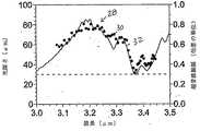
今度は図2を参照すると、この図は、透過深さおよび変位を生成するのに使用される光源の光透過深さおよび超音波振幅変位(縦座標)対光波長(横座標)の比較を示す。さらに具体的には、図2は、黒鉛エポキシサンプルを検査中に記録された実際のデータを反映するプロット22を示す。プロット22は、超音波変位を生成した発生ビームの波長に相互に関連付けられた黒鉛エポキシサンプルの超音波変位の測定された振幅を表す一連の点24を含む。測定された光深さは、光音響評価によって得られ、線26によって表される。測定された光深さおよび波長の単位はいずれもミクロンである。図2において、超音波変位振幅の値は、測定された振幅と光透過深さとの間の比例関係を明示するために正規化された。図2において、絶対値は、変位応答を示し、線26および一連の点24の相対形状は、対象の材料を識別するために使用しうる。さらに、制限された点を、測定に使用することができる。例えば、2つの所与の波長で測定された超音波振幅の比率は、対象の材料または硬化の度合いなどの特定の特性のいずれかを識別するために使用することができる。
Referring now to FIG. 2, this figure shows a comparison of the light transmission depth and ultrasonic amplitude displacement (ordinate) versus light wavelength (abscissa) of the light source used to generate the penetration depth and displacement. Show. More specifically, FIG. 2 shows a
従って、周知の複合材料の記録された光深さのデータは、測定された超音波変位の値および対応する発生ビームの波長から、材料を識別するための有効な比較基準を提供する。上記の通り、材料に関する識別は、材料の組成に限定されず、材料が適切に処理されている場合は、塗装膜、および材料内の組成の割合も含む。 Thus, the recorded optical depth data of known composite materials provides an effective comparison criterion for identifying materials from measured ultrasonic displacement values and corresponding generated beam wavelengths. As described above, the identification regarding the material is not limited to the composition of the material, and includes the coating film and the proportion of the composition in the material if the material is appropriately processed.
図3もまた、発生ビームにより生成された測定された振幅変位を表す正規化された点30と測定された光深さを反映する対応する線32とを比較するプロット28を示す。この例では、材料は、黒鉛BMIサンプルであった。図4もまた、所与の波長にわたって測定された光深さと、正規化された振幅データとを比較する。図4の例においては、物体は、塗装された黒鉛エポキシサンプルを含む。
FIG. 3 also shows a
図2〜4において、周知の分光技法、光音響、および2.5MHzでのレーザー超音波測定間の比較が表されている。光音響測定は、実験室において、複合部品から切り取られた、直径5ミリメートルの小さいサンプルに対して行われた。レーザー超音波測定は、複合部品自体に対して直接行われた。レーザー超音波測定は、波長を3.0ミクロンと3.5ミクロンとの間で調整可能な光学パラメーター式発振器を搭載したレーザー超音波システムにより得られた。この波長範囲は、C−H分子結合のストレッチモードに対応する。図2〜4は、超音波変位および材料内での光深さ間の比例関係を明示し、それによって、本方法を用いた材料分析の別の利点を示す。結果は、レーザー超音波測定が、異なる種類の材料間の簡単な区別を可能とすることも示す。
2-4, a comparison between well-known spectroscopic techniques, photoacoustics, and laser ultrasound measurements at 2.5 MHz is represented. Photoacoustic measurements were performed in the laboratory on a
より完璧な分析は、2.5MHz以外のいくつかの周波数において、超音波振幅を使用することができる。従って、本方法は、2.5MHzでの測定に限定されない。いくつかの超音波周波数またはブロードバンド超音波信号(より複雑ではあるが)の使用は、本明細書で開示される方法の範囲内に含まれる。 A more complete analysis can use ultrasound amplitudes at some frequencies other than 2.5 MHz. Therefore, this method is not limited to measurements at 2.5 MHz. The use of several ultrasound frequencies or broadband ultrasound signals (although more complex) is within the scope of the methods disclosed herein.
本方法の別の利点は、レーザー超音波検出システムが、欠陥条件の存在、および気孔率、異物、層間剥離、気孔率、異物(混入物)、剥離、ひび、および繊維配向および繊維密度などの繊維特性、部品の厚さ、およびバルクの機械的特性などのその他の一般的な材料特性を分析するのと同時に、対象の分光分析を実行することができることである。時間および資本の節約に加え、検査クーポンまたは制御サンプルの代わりに、物体自体に分析が実行されるため、より代表的な分光分析が達成可能である。上記の通り、走査は、製造された部品自体、より大きい完成された製品に装着された部品、または完成した組み立てられた完成された製品全般に対して実行することができる。 Another advantage of this method is that the laser ultrasound detection system is capable of detecting the presence of defect conditions and porosity, The ability to perform spectroscopic analysis of the object at the same time as analyzing other common material properties such as fiber properties, part thickness, and bulk mechanical properties. In addition to time and capital savings, a more representative spectroscopic analysis can be achieved because the analysis is performed on the object itself instead of an inspection coupon or control sample. As described above, the scan can be performed on the manufactured part itself, a part mounted on a larger finished product, or a finished assembled finished product in general.
発生ビームの波長の変更は、いくつかの方法で達成しうる。例えば、光学パラメトリック発振器は、所望の化学的識別を実行するのに十分な範囲にわたる発生レーザー波長を変更する能力を提供するために含むことができる。限られた数の異なる波長のみが必要とされる場合、ラーマンセル、ブリルアンセル、多波長レーザー、または複数のレーザーなどの装置を使用することが可能である。2つ以上の波長へのアクセスを付与する任意の装置またはシステムは、本明細書で説明される方法の1つの実施形態として考慮すべきである。 Changing the wavelength of the generated beam can be achieved in several ways. For example, an optical parametric oscillator can be included to provide the ability to change the generated laser wavelength over a range sufficient to perform the desired chemical identification. If only a limited number of different wavelengths are required, devices such as Raman cells, Brillouin cells, multi-wavelength lasers, or multiple lasers can be used. Any device or system that grants access to more than one wavelength should be considered as one embodiment of the methods described herein.
したがって、本明細書で開示される本発明は、その中に特有のその他のもの以外に、目標を実行し、上記の結果および利点を得るのによく適合される。本発明の現時点で好適な実施形態の1つを、開示の目的のために示してきたが、目的とする結果を達成するための手順の詳細において、多くの変更が存在する。これらおよびその他類似した改造は、それ自体を当業者に容易に示唆し、本明細書で開示される本発明の精神および添付の特許請求の範囲内に包含されることが意図される。 Accordingly, the invention disclosed herein is well adapted to carry out the goals and obtain the above results and advantages, in addition to others unique therein. While one presently preferred embodiment of the present invention has been presented for purposes of disclosure, there are many changes in the details of the procedure for achieving the desired results. These and other similar modifications will readily suggest themselves to those skilled in the art and are intended to be encompassed within the spirit of the invention disclosed herein and the appended claims.
Claims (14)
(a)発生されたレーザービームを前記検査対象の一部分に放射することによって、該一部分の表面に超音波変位を生じさせるステップと、
(b)前記発生されたレーザービームの波長を変化させ、該変更されたレーザービームを前記検査対象の前記一部分に放射することによって、該一部分の表面に超音波変位を生じさせるステップと、
(c)前記ステップ(a)及び(b)において生じた超音波変位の変位振幅を測定するステップと、
(d)前記ステップ(c)において測定されたそれぞれの超音波振幅と、前記発生されたレーザービームの波長との関係を表すプロットを形成するステップと、
(e)発生されたレーザービームの波長と、既知の組成の対象に対して該生成されたレーザービームを放射することによって得られた超音波変位との関係を表すプロットを提供するステップと、
(f)ステップ(d)及び(e)において得られたプロットを対比することによって、前記検査対象物の組成を判定するステップと
を含んでいることを特徴とする方法。 A method of analyzing a material to be inspected, comprising: (a) irradiating a generated laser beam to a part of the object to be examined to cause ultrasonic displacement on a surface of the part;
(B) changing the wavelength of the generated laser beam and emitting the altered laser beam to the portion of the object to be inspected to produce an ultrasonic displacement on the surface of the portion;
(C) measuring the displacement amplitude of the ultrasonic displacement generated in the steps (a) and (b);
(D) forming a plot representing the relationship between each ultrasonic amplitude measured in step (c) and the wavelength of the generated laser beam;
(E) providing a plot representing the relationship between the wavelength of the generated laser beam and the ultrasonic displacement obtained by emitting the generated laser beam to an object of known composition;
(F) determining the composition of the test object by comparing the plots obtained in steps (d) and (e).
前記ステップ(a)及び(b)で得られた超音波変位を測定し、それに基づいて、前記一部分の表面の光学的深さを推定し、前記生成されたレーザービームの波長と推定された光学的深さとの関係を表すプロットを形成し、該プロットと前記ステップ(d)において得られたプロットとを組み合わせるステップ
を含んでいることを特徴とする方法。 The method according to any one of claims 1 to 4, further comprising:
The ultrasonic displacement obtained in steps (a) and (b) is measured, and based on this, the optical depth of the surface of the part is estimated, and the wavelength estimated as the wavelength of the generated laser beam. Forming a plot representing a relationship to the target depth and combining the plot with the plot obtained in step (d).
既知の組成を有する検査対象の表面の超音波変位の変位振幅の値からなる対比データ配列を形成するステップであって、該変位振幅は、当該超音波変位を生じたレーザー波の波長に相関していることを特徴とする方法。 6. The method according to any of claims 1-5, further comprising:
Forming a contrast data array comprising values of the displacement amplitude of the ultrasonic displacement of the surface to be inspected having a known composition, the displacement amplitude being correlated to the wavelength of the laser wave that caused the ultrasonic displacement. A method characterized by that.
(a)2つ以上の既知の波長で動作するパルス状の発生レーザービームを用いて、前記物体の一部分上に超音波変位を生じさせるステップと、
(b)前記既知の波長それぞれで発生された、前記物体の一部分上の前記超音波変位の変位振幅を測定するステップと、
(c)前記既知の波長それぞれと、該既知の波長で発生された前記変位振幅とを含む測定されたデータ配列を生成するステップと、
(d)前記測定されたデータ配列を、既知の材料から得られたデータ配列と比較するステップであって、データ配列は、超音波変位と、該超音波変位を生成するために用いられた生成レーザービームの波長とを含んでいる、ステップと、
(e)前記測定されたデータ配列と、前記ステップ(d)の比較結果に基づいて、前記物体の組成を識別するステップと
を含むことを特徴とする方法。 A method for analyzing an object,
(A) generating an ultrasonic displacement on a portion of the object using a pulsed generated laser beam operating at two or more known wavelengths;
(B) measuring a displacement amplitude of the ultrasonic displacement on a portion of the object generated at each of the known wavelengths;
(C) generating a measured data array that includes each of the known wavelengths and the displacement amplitude generated at the known wavelengths;
(D) is the measured data array, comprising the steps of: comparing the obtained data sequence from the known materials, the data sequence generator used to generate the ultrasonic displacements, the ultrasonic displacement A step including a wavelength of the laser beam;
(E) identifying the composition of the object based on the measured data array and the comparison result of step (d).
前記対象物体上に発生レーザービームを接触させるステップと、
前記発生レーザービームによって、前記対象物体上に超音波変位を発生させるステップと、
前記超音波変位を測定するステップと、
前記発生レーザービームの波長を変更するステップと、
異なる波長の発生レーザービームによって、前記対象物体上に別の超音波変位を発生させるステップと、
前記別の超音波変位を測定するステップと、
超音波変位と発生レーザービームの波長とを含む測定されたデータ配列を形成するステップと、
測定された前記超音波変位を、該変位を発生させるのに使用された前記発生レーザービームの波長と相互に関連付けるステップと、
前記測定されたデータ配列を、既知の材料に関するデータ配列と比較するステップと、
前記比較するステップにおける比較結果に基づいて、前記対象物体の材料を判定するステップと、
前記超音波変位を分析することによって、前記対象物体内の欠陥を検出するステップと
を備えていることを特徴とする方法。 A method of ultrasonic inspection of a target object,
Contacting the generated laser beam on the target object;
Generating ultrasonic displacement on the target object with the generated laser beam;
Measuring the ultrasonic displacement;
Changing the wavelength of the generated laser beam;
Generating another ultrasonic displacement on the target object with generated laser beams of different wavelengths;
Measuring said another ultrasonic displacement;
Forming a measured data array including ultrasonic displacement and wavelength of the generated laser beam;
Correlating the measured ultrasonic displacement with the wavelength of the generated laser beam used to generate the displacement;
Comparing the measured data array to a data array for a known material;
Determining a material of the target object based on a comparison result in the comparing step;
And detecting a defect in the target object by analyzing the ultrasonic displacement.
Applications Claiming Priority (3)
| Application Number | Priority Date | Filing Date | Title |
|---|---|---|---|
| US12/120,907 | 2008-05-15 | ||
| US12/120,907 US8054470B2 (en) | 2008-05-15 | 2008-05-15 | Method and apparatus for spectroscopic characterization of samples using a laser-ultrasound system |
| PCT/US2009/043906 WO2009140468A2 (en) | 2008-05-15 | 2009-05-14 | Method and apparatus for spectroscopic characterization of samples using a laser-ultrasound system |
Publications (3)
| Publication Number | Publication Date |
|---|---|
| JP2011521232A JP2011521232A (en) | 2011-07-21 |
| JP2011521232A5 JP2011521232A5 (en) | 2012-05-31 |
| JP5443478B2 true JP5443478B2 (en) | 2014-03-19 |
Family
ID=41258466
Family Applications (1)
| Application Number | Title | Priority Date | Filing Date |
|---|---|---|---|
| JP2011509689A Expired - Fee Related JP5443478B2 (en) | 2008-05-15 | 2009-05-14 | Method and apparatus for spectral characterization of samples using a laser ultrasound system |
Country Status (11)
| Country | Link |
|---|---|
| US (1) | US8054470B2 (en) |
| EP (1) | EP2286214B1 (en) |
| JP (1) | JP5443478B2 (en) |
| KR (1) | KR101351231B1 (en) |
| CN (1) | CN102089651B (en) |
| AU (1) | AU2009246272B2 (en) |
| BR (1) | BRPI0912676A2 (en) |
| CA (1) | CA2724326C (en) |
| IL (1) | IL209292A (en) |
| TW (1) | TWI460946B (en) |
| WO (1) | WO2009140468A2 (en) |
Families Citing this family (5)
| Publication number | Priority date | Publication date | Assignee | Title |
|---|---|---|---|---|
| US8522614B2 (en) * | 2010-05-26 | 2013-09-03 | General Electric Company | In-line inspection methods and closed loop processes for the manufacture of prepregs and/or laminates comprising the same |
| FR2981450B1 (en) * | 2011-10-17 | 2014-06-06 | Eads Europ Aeronautic Defence | SYSTEM AND METHOD FOR CONTROLLING THE QUALITY OF AN OBJECT |
| CN102506781B (en) * | 2011-11-17 | 2014-02-12 | 江苏大学 | Laser ultrasonic thickness measuring method and laser ultrasonic thickness measuring device capable of being used for field detection |
| KR20170007181A (en) | 2015-07-10 | 2017-01-18 | 3스캔 인크. | Spatial multiplexing of histological stains |
| IL243712A0 (en) * | 2016-01-20 | 2016-04-21 | Yeda Res & Dev | Devices and methods to measure small displacements |
Family Cites Families (7)
| Publication number | Priority date | Publication date | Assignee | Title |
|---|---|---|---|---|
| DK160590C (en) * | 1988-09-12 | 1991-09-16 | Fls Airloq As | METHOD OF DETECTING A GAS TYPE BY PHOTOACUSTIC SPECTROSCOPY |
| US6041020A (en) * | 1997-04-21 | 2000-03-21 | University Of Delaware | Gas-coupled laser acoustic detection |
| US6335943B1 (en) * | 1999-07-27 | 2002-01-01 | Lockheed Martin Corporation | System and method for ultrasonic laser testing using a laser source to generate ultrasound having a tunable wavelength |
| US6176135B1 (en) | 1999-07-27 | 2001-01-23 | Marc Dubois | System and method for laser-ultrasonic frequency control using optimal wavelength tuning |
| JP4789394B2 (en) * | 2000-07-14 | 2011-10-12 | ロッキード マーティン コーポレイション | System and method for detecting porosity of composite materials using ultrasound |
| US6378387B1 (en) | 2000-08-25 | 2002-04-30 | Aerobotics, Inc. | Non-destructive inspection, testing and evaluation system for intact aircraft and components and method therefore |
| US6668654B2 (en) * | 2001-08-15 | 2003-12-30 | Lockheed Martin Corporation | Method and apparatus for generating specific frequency response for ultrasound testing |
-
2008
- 2008-05-15 US US12/120,907 patent/US8054470B2/en active Active
-
2009
- 2009-05-14 CA CA2724326A patent/CA2724326C/en not_active Expired - Fee Related
- 2009-05-14 BR BRPI0912676A patent/BRPI0912676A2/en not_active IP Right Cessation
- 2009-05-14 KR KR1020107028048A patent/KR101351231B1/en not_active IP Right Cessation
- 2009-05-14 EP EP09747550.3A patent/EP2286214B1/en not_active Not-in-force
- 2009-05-14 WO PCT/US2009/043906 patent/WO2009140468A2/en active Application Filing
- 2009-05-14 JP JP2011509689A patent/JP5443478B2/en not_active Expired - Fee Related
- 2009-05-14 CN CN200980125463.8A patent/CN102089651B/en not_active Expired - Fee Related
- 2009-05-14 AU AU2009246272A patent/AU2009246272B2/en not_active Ceased
- 2009-05-15 TW TW098116309A patent/TWI460946B/en not_active IP Right Cessation
-
2010
- 2010-11-14 IL IL209292A patent/IL209292A/en not_active IP Right Cessation
Also Published As
| Publication number | Publication date |
|---|---|
| BRPI0912676A2 (en) | 2016-01-26 |
| CA2724326C (en) | 2014-07-08 |
| US8054470B2 (en) | 2011-11-08 |
| CN102089651A (en) | 2011-06-08 |
| WO2009140468A3 (en) | 2010-01-07 |
| IL209292A (en) | 2013-03-24 |
| EP2286214A2 (en) | 2011-02-23 |
| TWI460946B (en) | 2014-11-11 |
| CA2724326A1 (en) | 2009-11-19 |
| EP2286214B1 (en) | 2015-02-18 |
| JP2011521232A (en) | 2011-07-21 |
| KR101351231B1 (en) | 2014-01-13 |
| WO2009140468A2 (en) | 2009-11-19 |
| CN102089651B (en) | 2014-12-24 |
| IL209292A0 (en) | 2011-01-31 |
| US20090284752A1 (en) | 2009-11-19 |
| AU2009246272B2 (en) | 2014-01-09 |
| TW200952297A (en) | 2009-12-16 |
| AU2009246272A1 (en) | 2009-11-19 |
| KR20110010112A (en) | 2011-01-31 |
Similar Documents
| Publication | Publication Date | Title |
|---|---|---|
| US7757558B2 (en) | Method and apparatus for inspecting a workpiece with angularly offset ultrasonic signals | |
| JP5587700B2 (en) | Method and system for classifying the type and severity of defects in a weld | |
| EP2975396B1 (en) | Nondestructive inspection using ultrasound | |
| US9074927B2 (en) | Methods for non-destructively evaluating a joined component | |
| JP2011523459A (en) | Vision system for scan planning of ultrasound examination | |
| JP5443478B2 (en) | Method and apparatus for spectral characterization of samples using a laser ultrasound system | |
| GB2545271A (en) | Determining physical characteristics of a structure | |
| US20130088724A1 (en) | Method and apparatus for the inspection of sandwich structures using laser-induced resonant frequencies | |
| JP2011033628A (en) | Method and system for detecting defect in welded structure using pattern matching | |
| Faëse et al. | Beam shaping to enhance zero group velocity Lamb mode generation in a composite plate and nondestructive testing application | |
| JP2012063330A (en) | Method for non-contact and non-destructive evaluation of multilayer coating film, and device using the same | |
| CA2770553A1 (en) | Method and device for inspecting the quality of a formed thermoplastic fiber-reinforced plastic component | |
| JP6121873B2 (en) | Laser ultrasonic inspection apparatus and method | |
| US7876453B1 (en) | Laser ultrasonic multi-component imaging | |
| JP2011521232A5 (en) | ||
| Fayazbakhsh et al. | High frequency phased array ultrasonic testing of thermoplastic tensile specimens manufactured by fused filament fabrication with embedded defects | |
| Jatzlau et al. | Identification of flawed CFRP samples using local acoustic resonance spectroscopy (LARS) | |
| Imano | Detection of Unbonded Defect under Surface of Material Using Phase Information of Rayleigh and A0 Mode Lamb Waves. | |
| Machado et al. | Inspection benchmarking of Fiber Reinforced Polymers produced by Additive Manufacturing | |
| GB2619959A (en) | Acoustic inspection method and apparatus therefor | |
| Djordjevic | Laser ultrasonic guided wave methods for defect detection and materials characterisation | |
| Bond et al. | Development of Tools for High Volume, High Speed Non-Destructive Inspection of Carbon Fiber Reinforced Plastics (Final Technical Report) | |
| Saxena et al. | Propogation loss with frequency of ultrasound guided waves in a composite metal-honeycomb structure | |
| GR1009561B (en) | Materials real-time integrity assesment and quality assurance (martian-qa) |
Legal Events
| Date | Code | Title | Description |
|---|---|---|---|
| A521 | Request for written amendment filed |
Free format text: JAPANESE INTERMEDIATE CODE: A523 Effective date: 20110119 |
|
| A621 | Written request for application examination |
Free format text: JAPANESE INTERMEDIATE CODE: A621 Effective date: 20111202 |
|
| A521 | Request for written amendment filed |
Free format text: JAPANESE INTERMEDIATE CODE: A523 Effective date: 20120404 |
|
| A131 | Notification of reasons for refusal |
Free format text: JAPANESE INTERMEDIATE CODE: A131 Effective date: 20130802 |
|
| RD02 | Notification of acceptance of power of attorney |
Free format text: JAPANESE INTERMEDIATE CODE: A7422 Effective date: 20131003 |
|
| RD03 | Notification of appointment of power of attorney |
Free format text: JAPANESE INTERMEDIATE CODE: A7423 Effective date: 20131003 |
|
| A521 | Request for written amendment filed |
Free format text: JAPANESE INTERMEDIATE CODE: A523 Effective date: 20131021 |
|
| RD04 | Notification of resignation of power of attorney |
Free format text: JAPANESE INTERMEDIATE CODE: A7424 Effective date: 20131009 |
|
| TRDD | Decision of grant or rejection written | ||
| A01 | Written decision to grant a patent or to grant a registration (utility model) |
Free format text: JAPANESE INTERMEDIATE CODE: A01 Effective date: 20131126 |
|
| A61 | First payment of annual fees (during grant procedure) |
Free format text: JAPANESE INTERMEDIATE CODE: A61 Effective date: 20131219 |
|
| R150 | Certificate of patent or registration of utility model |
Free format text: JAPANESE INTERMEDIATE CODE: R150 |
|
| R250 | Receipt of annual fees |
Free format text: JAPANESE INTERMEDIATE CODE: R250 |
|
| LAPS | Cancellation because of no payment of annual fees |