JP5443119B2 - Clothes dryer and washing dryer - Google Patents
Clothes dryer and washing dryer Download PDFInfo
- Publication number
- JP5443119B2 JP5443119B2 JP2009238909A JP2009238909A JP5443119B2 JP 5443119 B2 JP5443119 B2 JP 5443119B2 JP 2009238909 A JP2009238909 A JP 2009238909A JP 2009238909 A JP2009238909 A JP 2009238909A JP 5443119 B2 JP5443119 B2 JP 5443119B2
- Authority
- JP
- Japan
- Prior art keywords
- air
- drying
- drum
- clothes
- outlet
- Prior art date
- Legal status (The legal status is an assumption and is not a legal conclusion. Google has not performed a legal analysis and makes no representation as to the accuracy of the status listed.)
- Active
Links
Images


Classifications
-
- D—TEXTILES; PAPER
- D06—TREATMENT OF TEXTILES OR THE LIKE; LAUNDERING; FLEXIBLE MATERIALS NOT OTHERWISE PROVIDED FOR
- D06F—LAUNDERING, DRYING, IRONING, PRESSING OR FOLDING TEXTILE ARTICLES
- D06F25/00—Washing machines with receptacles, e.g. perforated, having a rotary movement, e.g. oscillatory movement, the receptacle serving both for washing and for centrifugally separating water from the laundry and having further drying means, e.g. using hot air
-
- D—TEXTILES; PAPER
- D06—TREATMENT OF TEXTILES OR THE LIKE; LAUNDERING; FLEXIBLE MATERIALS NOT OTHERWISE PROVIDED FOR
- D06F—LAUNDERING, DRYING, IRONING, PRESSING OR FOLDING TEXTILE ARTICLES
- D06F2103/00—Parameters monitored or detected for the control of domestic laundry washing machines, washer-dryers or laundry dryers
- D06F2103/02—Characteristics of laundry or load
- D06F2103/04—Quantity, e.g. weight or variation of weight
-
- D—TEXTILES; PAPER
- D06—TREATMENT OF TEXTILES OR THE LIKE; LAUNDERING; FLEXIBLE MATERIALS NOT OTHERWISE PROVIDED FOR
- D06F—LAUNDERING, DRYING, IRONING, PRESSING OR FOLDING TEXTILE ARTICLES
- D06F2103/00—Parameters monitored or detected for the control of domestic laundry washing machines, washer-dryers or laundry dryers
- D06F2103/28—Air properties
- D06F2103/36—Flow or velocity
-
- D—TEXTILES; PAPER
- D06—TREATMENT OF TEXTILES OR THE LIKE; LAUNDERING; FLEXIBLE MATERIALS NOT OTHERWISE PROVIDED FOR
- D06F—LAUNDERING, DRYING, IRONING, PRESSING OR FOLDING TEXTILE ARTICLES
- D06F2103/00—Parameters monitored or detected for the control of domestic laundry washing machines, washer-dryers or laundry dryers
- D06F2103/38—Time, e.g. duration
-
- D—TEXTILES; PAPER
- D06—TREATMENT OF TEXTILES OR THE LIKE; LAUNDERING; FLEXIBLE MATERIALS NOT OTHERWISE PROVIDED FOR
- D06F—LAUNDERING, DRYING, IRONING, PRESSING OR FOLDING TEXTILE ARTICLES
- D06F2105/00—Systems or parameters controlled or affected by the control systems of washing machines, washer-dryers or laundry dryers
- D06F2105/16—Air properties
- D06F2105/24—Flow or velocity
-
- D—TEXTILES; PAPER
- D06—TREATMENT OF TEXTILES OR THE LIKE; LAUNDERING; FLEXIBLE MATERIALS NOT OTHERWISE PROVIDED FOR
- D06F—LAUNDERING, DRYING, IRONING, PRESSING OR FOLDING TEXTILE ARTICLES
- D06F2105/00—Systems or parameters controlled or affected by the control systems of washing machines, washer-dryers or laundry dryers
- D06F2105/32—Air flow control means
-
- D—TEXTILES; PAPER
- D06—TREATMENT OF TEXTILES OR THE LIKE; LAUNDERING; FLEXIBLE MATERIALS NOT OTHERWISE PROVIDED FOR
- D06F—LAUNDERING, DRYING, IRONING, PRESSING OR FOLDING TEXTILE ARTICLES
- D06F58/00—Domestic laundry dryers
- D06F58/02—Domestic laundry dryers having dryer drums rotating about a horizontal axis
-
- D—TEXTILES; PAPER
- D06—TREATMENT OF TEXTILES OR THE LIKE; LAUNDERING; FLEXIBLE MATERIALS NOT OTHERWISE PROVIDED FOR
- D06F—LAUNDERING, DRYING, IRONING, PRESSING OR FOLDING TEXTILE ARTICLES
- D06F58/00—Domestic laundry dryers
- D06F58/32—Control of operations performed in domestic laundry dryers
- D06F58/34—Control of operations performed in domestic laundry dryers characterised by the purpose or target of the control
Description
本発明は、衣類の乾燥を行う衣類乾燥機および洗濯機能と衣類乾燥機能とを具備した洗濯乾燥機に関するものである。 The present invention relates to a clothes dryer for drying clothes and a washing / drying machine having a washing function and a clothes drying function.
従来、ドラム式の衣類乾燥機や洗濯乾燥機は、乾燥用空気を風路を通してドラム内に送風し、ドラムに投入された衣類に乾燥用空気を接触させて衣類から水分を奪い衣類を乾燥させるとともに、湿気を含んで高湿度となった乾燥用空気をドラム外の風路に排出するものである。特に、限られた狭いドラムの空間内で衣類の乾燥を行うことから、乾燥後の衣類は強いシワがついた状態になるという問題があり、その解決に種々の方法が考えられている。(例えば、特許文献1参照)。 Conventionally, drum-type clothes dryers and washing dryers blow drying air into the drum through the air passage, and the drying air is brought into contact with the clothes put in the drum to remove moisture from the clothes and dry the clothes. At the same time, the drying air that has become humid due to moisture is discharged to the air path outside the drum. In particular, since the clothes are dried in a limited space of a narrow drum, there is a problem that the clothes after drying are in a state of strong wrinkles, and various methods have been considered for solving the problem. (For example, refer to Patent Document 1).
図8は、特許文献1に記載された従来のドラム式洗濯乾燥機を示すものである。同図に示すように、従来のドラム式洗濯乾燥機では、乾燥工程中に、第1の風路121と第2の風路122とから乾燥用空気を回転ドラム123内部に吹き込むことによって風量を増加し、衣類124からの水分の蒸発を促進して乾燥時間の短縮を図っている。さらに、第2の風路122においては、回転ドラム123の開口部下部に設けられた第2の吹込み口125から高圧な空気を回転ドラム123内の衣類124に高速で吹き付けている。このようにして、吹き付けた空気で衣類124を持ち上げながら攪拌することにより、衣類124にシワが発生するのを抑制して乾燥仕上がりの向上も図っている。
FIG. 8 shows a conventional drum-type washing and drying machine described in
しかしながら、前記従来の構成では、高圧高速の空気を衣類124に吹き付けているが、一般に、同一風量の空気をより高圧で高速に吹き付けるには、その分仕事量が増加するため、送風ファン用モータの消費電力は大きくなる。また、前記従来の構成では、回転ドラム123内部に吹き込む風量を増加するために2つの送風ファン用モータを使用しており、消費電力はさらに大きくなる。よって、前記従来のドラム式洗濯乾燥機は、乾燥時間の短縮やシワ伸ばしを実現する構成として、低消費電力化の面で課題を有していた。
However, in the conventional configuration, high-pressure and high-speed air is blown onto the
本発明は、上記の課題を解決するためになされたものであり、低消費電力量でシワの少ない乾燥ができる衣類乾燥機および洗濯乾燥機を提供することを目的とするものである。 The present invention has been made to solve the above problems, and an object of the present invention is to provide a clothes dryer and a washing dryer that can dry with low power consumption and low wrinkles.
本発明に係る衣類乾燥機は、乾燥対象の衣類を収容する収容部と、前記収容部に開口した第1吹出口を有する第1風路と、前記第1吹出口よりも空気通過断面積が小さい第2吹出口を有する第2風路と、前記第1風路と前記第2風路とを選択的に切り換える風路切換部と、前記第1風路が選択されているときには前記第2風路が選択されているときよりも大風量の乾燥用空気が前記第1吹出口から収容部内へ吹き出される一方、前記第2風路が選択されているときには前記第1風路が選択されているときよりも高圧高速の乾燥用空気が前記第2吹出口から収容部内へ吹き出されるように乾燥用空気を送風する送風部と、乾燥工程の途中で、前記第1風路と前記第2風路とが選択的に切り換えられるように前記風路切換部を制御する制御部とを備える。
The clothes dryer according to the present invention has a housing part that houses clothes to be dried, a first air passage having a first air outlet that opens in the housing part, and an air passage cross-sectional area that is larger than that of the first air outlet. A second air passage having a small second air outlet, an air passage switching unit that selectively switches between the first air passage and the second air passage, and the second air passage when the first air passage is selected. A larger amount of drying air is blown from the first air outlet into the housing portion than when the air path is selected, while when the second air path is selected, the first air path is selected. A high-speed and high-speed drying air from the second blow-out port to blow into the housing portion, and a blowing unit that blows the drying air in the middle of the drying step. A control unit for controlling the air path switching unit so that the two air paths are selectively switched; Obtain.
上記の構成によれば、乾燥開始から終了までの乾燥工程の間での衣類の乾燥の進み具合とシワ固着の仕方に応じて、消費電力量を少なく乾燥する工程と、シワが固着されないように衣類を常に動かして繊維を伸ばす工程とを分けて乾燥工程を実行するものとなる。 According to said structure, according to the progress of drying of clothing between the drying processes from the start of drying to the end and the way of wrinkle fixation, the process of drying with less power consumption and the wrinkles are not fixed. The drying process is executed separately from the process of constantly moving the clothes to stretch the fibers.
すなわち、衣類を収容する収容部に乾燥用空気を導入する風路として、第1風路および第2風路の2つの風路が設けられており、当該2つの風路は風路切換部により切り換えることができる。ここで、第1風路の第1吹出口は、第2風路の第2吹出口よりも空気通過断面積が大きく、圧力損失が少ない。そして、この第1風路が選択されているときには、第2風路が選択されているときよりも大風量の乾燥用空気が、収容部に開口した第1吹出口から収容部内へ吹き出される。乾燥運転序盤の衣類に水分が多く含まれた状態では、空気通過断面積が大きく圧力損失の少ない第1風路で大風量の乾燥用空気を衣類に当て、多くの水分を蒸発させて乾燥時間を短縮する。この場合、風路の圧力損失が少ないため、比較的少ない消費電力で送風部を駆動しても、大風量の風を得ることができる。よって、大風量の風による乾燥時間の短縮と、消費電力量の低減とを図れる。
That is, two air paths, a first air path and a second air path, are provided as air paths for introducing the drying air into the housing section that stores the clothes, and the two air paths are provided by the air path switching section. Can be switched. Here, the first air outlet of the first air passage has a larger air passage cross-sectional area and less pressure loss than the second air outlet of the second air passage. When the first air path is selected, drying air having a larger air volume than that when the second air path is selected is blown into the housing portion from the first air outlet opening in the housing portion. . When the clothing in the early stage of the drying operation contains a lot of moisture, the drying time is set by applying a large amount of drying air to the clothing in the first air passage with a large air cross-sectional area and low pressure loss, and evaporating much moisture. To shorten. In this case, since the pressure loss in the air passage is small, a large amount of wind can be obtained even if the air blowing unit is driven with relatively low power consumption. Therefore, it is possible to shorten the drying time due to the large air volume and reduce the power consumption.
一方、第2風路の第2吹出口は、第1吹出口よりも空気通過断面積が小さくなっている。そして、第2風路が選択されているときには、第1風路が選択されているときよりも高圧高速の乾燥用空気が、第2吹出口から収容部内へ吹き出される。この場合、高圧高速の風によって衣類(収容部の前方に偏り易い長袖衣類など)が押し広げられるため、シワの発生を低減することができる。そして、このように構成された第1風路および第2風路を、乾燥工程の途中で選択的に切り換える(例えば衣類にシワが発生し難い期間については第1風路、シワが発生し易い期間については第2風路とする)ことにより、1つの送風部で衣類乾燥が可能であり且つ乾燥途中では高風速よりも消費電力の少ない大風量で乾燥するため、低消費電力量でもシワの少ない乾燥ができる。
On the other hand, the air outlet cross-sectional area of the second air outlet of the second air passage is smaller than that of the first air outlet. And when the 2nd air path is selected, the high-pressure high-speed drying air is blown out from the 2nd blower outlet in the accommodating part rather than the time when the 1st air path is selected. In this case, since the clothes (such as long-sleeved clothes that tend to be biased to the front of the housing portion) are spread by the high-pressure and high-speed wind, the generation of wrinkles can be reduced. Then, the first air path and the second air path thus configured are selectively switched in the middle of the drying process (for example, the first air path and the wrinkle are easily generated during a period when the wrinkle is not easily generated in the clothes. For the period, the second air path is used), and it is possible to dry clothes with a single air blower, and during drying, the air is dried with a large air volume that consumes less power than the high wind speed. Less drying is possible.
また、上記の構成において、前記乾燥用空気を前記収容部の外へ排出する排出口は、相対的に前記第2吹出口により近く前記第1吹出口からはより遠い位置に形成されていることが望ましい。 Further, in the above configuration, the discharge port for discharging the drying air to the outside of the housing portion is formed at a position relatively closer to the second air outlet and further from the first air outlet. Is desirable.
上記の構成によれば、排出口、第1吹出口および第2吹出口の相対的な位置関係は、排出口と第1吹出口とが近く、排出口と第2吹出口とが遠くなっている。このように、排出口と第2吹出口との距離を離すことにより、第1吹出口からの送風中は、収容部内の衣類と乾燥用空気とが効率よく接触し、少ない消費電力量で効果的に衣類の乾燥ができる。一方、第2吹出口からの送風中は、排気口が第2吹出口の近くに存在しても、第2吹出口からは高圧高風速の乾燥用空気が吹き出しているため、乾燥用空気は排気口から離れた位置まで到達することができ、衣類と乾燥用空気との接触が悪くなることなくシワを伸ばす効果を維持できる。これによって、従来例のように、高圧で高速の乾燥用空気を常に吹き出し、さらに風量を増加するために2つの送風部を常に使用するよりも、トータルの消費電力量が少なく、衣類のシワも少ない乾燥仕上がりを実現することができる。 According to said structure, as for the relative positional relationship of a discharge outlet, a 1st blower outlet, and a 2nd blower outlet, a discharge outlet and a 1st blower outlet are near, and a discharge outlet and a 2nd blower outlet become far. Yes. As described above, by separating the distance between the discharge port and the second air outlet, the clothes in the housing and the drying air are efficiently in contact with each other while the air is being blown from the first air outlet. The clothes can be dried. On the other hand, during the blowing from the second air outlet, even if the exhaust port exists near the second air outlet, the drying air of high pressure and high wind speed is blown out from the second air outlet, so the drying air is It is possible to reach a position away from the exhaust port, and it is possible to maintain the effect of stretching wrinkles without deteriorating the contact between the clothes and the drying air. As a result, as in the conventional example, the total amount of power consumption is smaller and the wrinkles of clothing are less than the case where the high-speed and high-speed drying air is always blown out, and the two air blowing units are always used to further increase the air volume. Less dry finish can be achieved.
また、上記の制御部は、少なくとも前記収容部内の衣類の乾燥率が略90%から略100%となる乾燥中盤期間に、前記高圧高速の乾燥用空気が第2吹出口から吹き出されるように前記第2風路を選択することが望ましい。 In addition, the control unit is configured so that the high-pressure and high-speed drying air is blown out from the second air outlet at least during the middle drying period in which the drying rate of the clothes in the storage unit is approximately 90% to approximately 100%. It is desirable to select the second air path.
上記の構成において、衣類の乾燥率が略90%から略100%となる乾燥中盤期間は、乾燥工程において最もシワが発生して固着し易い期間であるといえる。少なくとも、この乾燥中盤期間には、高圧高速の乾燥用空気を第2吹出口から吹き出すこととし、効果的にシワの発生を低減できる。 In the above configuration, the drying middle period in which the drying rate of the garment is approximately 90% to approximately 100% can be said to be a period in which wrinkles are most likely to occur and adhere in the drying process. At least during this intermediate drying period, high-pressure and high-speed drying air is blown out from the second air outlet, and the generation of wrinkles can be effectively reduced.
また、上記の制御部は、乾燥工程開始から第1所定時間が経過するまでの乾燥序盤期間に、前記大風量の乾燥用空気が前記第1吹出口から吹き出されるように前記第1風路を選択するとともに、前記第1所定時間が経過した後の乾燥中盤以降は前記高圧高速の乾燥用空気が第2吹出口から吹き出されるように前記第2風路を選択ことが望ましい。 In addition, the control unit may include the first air path so that the large amount of drying air is blown out from the first air outlet during a drying early period from the start of the drying process until the first predetermined time elapses. It is preferable that the second air path is selected so that the high-pressure and high-speed drying air is blown out from the second outlet after the middle of the drying after the first predetermined time has elapsed.
上記の構成において、乾燥工程開始から第1所定時間が経過するまでの乾燥序盤期間には、空気通過断面積が大きく圧力損失の少ない第1風路を使用し、大風量の乾燥用空気を衣類に当てる。この場合、第1風路の圧力損失が少ないため、比較的少ない消費電力で送風部を駆動しても、大風量の風を得ることができる。よって、大風量の乾燥用空気による乾燥時間の短縮と、消費電力量の低減とを図れる。そして、第1所定時間が経過した後の乾燥中盤以降においては、第2風路に切り換える。この乾燥中盤以降は、シワが発生して固着し易い期間を含むが、第2吹出口から吹き出される高圧高速の乾燥用空気によって衣類が常時押し広げられるため、シワが低減する。これにより、従来例のように、高圧で高速の乾燥用空気を常に吹き出し、さらに風量を増加するために2つの送風部を常に使用するよりも、トータルの消費電力量が少なく、衣類のシワも少ない良好な乾燥仕上がりを実現することができる。 In the above-described configuration, the first air passage having a large air passage cross-sectional area and a small pressure loss is used during the initial drying period from the start of the drying process until the first predetermined time elapses, and a large amount of air for drying is applied to the clothing. To hit. In this case, since the pressure loss of the first air passage is small, a large amount of wind can be obtained even when the air blowing unit is driven with relatively low power consumption. Therefore, it is possible to shorten the drying time by using a large amount of air for drying and reduce the power consumption. Then, after the first predetermined time has passed, the second air path is switched after the middle drying stage. After the middle stage of drying, there is a period during which wrinkles are likely to occur and stick, but the clothes are constantly pushed out by the high-pressure and high-speed drying air blown from the second air outlet, so that wrinkles are reduced. As a result, as in the conventional example, the high-speed and high-speed drying air is constantly blown out, and the total power consumption is smaller than in the case where two air blowing units are always used to increase the air volume. A small dry finish can be realized.
また、上記の制御部は、乾燥工程開始からの時間が前記第1所定時間よりも長い第2所定時間が経過した後の乾燥終盤期間に、再度、前記大風量の乾燥用空気が前記第1吹出口から吹き出されるように前記第1風路を選択することが望ましい。 In addition, the control unit may again supply the large amount of drying air to the first air during the final drying period after the second predetermined time that is longer than the first predetermined time has elapsed since the start of the drying process. It is desirable to select the first air path so that the air is blown out from the air outlet.
上記の構成によれば、乾燥工程開始から第2所定時間が経過した後の乾燥終盤期間においては、再度、第1風路に切り換える。この乾燥終盤期間は、衣類に含まれる水分量が少なくなり、この少ない水分が乾燥用空気と接触して蒸発するには時間がかかる。この様な状態では、大風量の乾燥用空気を収容部内に送風して水分と乾燥用空気とが接触する機会を多くすることが必要であり、低消費電力で大風量が得られることが望ましい。そこで、空気通過断面積が大きく圧力損失の少ない第1風路を使用し、大風量の乾燥用空気を衣類に当てる。この場合、第1風路の圧力損失が少ないため、少ない消費電力で送風部を駆動しても、大風量の風を得ることができる。よって、乾燥終盤期間における乾燥時間の短縮およびこの間の消費電力量の低減を図れ、トータルの消費電力量をさらに低減することができる。 According to said structure, it switches to a 1st air path again in the last stage of drying after 2nd predetermined time passes since the drying process start. During the final drying period, the amount of moisture contained in the clothing is reduced, and it takes time for the little moisture to come into contact with the drying air and evaporate. In such a state, it is necessary to increase the chance that the moisture and the drying air come into contact with each other by blowing a large amount of drying air into the housing portion, and it is desirable to obtain a large air volume with low power consumption. . Therefore, the first air passage having a large air passage cross-sectional area and a small pressure loss is used, and a large amount of air for drying is applied to the clothes. In this case, since the pressure loss of the first air passage is small, a large amount of wind can be obtained even if the blower is driven with low power consumption. Therefore, the drying time in the final drying period can be shortened and the power consumption during this period can be reduced, and the total power consumption can be further reduced.
また、上記の制御部は、乾燥工程開始から第2所定時間が経過するまでの乾燥序盤および乾燥中盤期間に、前記高圧高速の乾燥用空気が第2吹出口から吹き出されるように前記第2風路を選択するとともに、前記第2所定時間が経過した後の乾燥終盤期間に、前記大風量の乾燥用空気が前記第1吹出口から吹き出されるように前記第1風路を選択することが望ましい。 In addition, the control unit is configured to cause the high-pressure and high-speed drying air to be blown out from the second air outlet during the drying early stage and the middle drying period until the second predetermined time elapses from the start of the drying process. The air path is selected, and the first air path is selected such that the large amount of drying air is blown out from the first air outlet during the final drying period after the second predetermined time has elapsed. Is desirable.
上記の構成によれば、乾燥工程開始から第2所定時間が経過するまでの乾燥序盤および乾燥中盤期間に、第2風路を使用する。繊維の種類、布の織り方等々により、脱水終了後の衣類の水分含有量は、大きく異なる。化繊を多く含む衣類の場合は、脱水後の水分含有量すなわち初期乾燥率は、かなり高く90%近いものとなる。このような衣類の場合、乾燥序盤及び乾燥中盤期間にシワが発生して固着し易い期間を含むが、第2風路の第2吹出口から吹き出される高圧高速の乾燥用空気によって衣類が常時押し広げられるため、シワが低減する。その後、第2所定時間経過後の乾燥終盤期間においては、第1風路を使用する。上述のように乾燥終盤期間は、衣類に含まれる水分量が少なく、この少ない水分が乾燥用空気と接触して蒸発するには時間がかかる。そこで、乾燥終盤期間に、第1風路の第1出口から大風量の乾燥用空気を収容部内に送風して水分と乾燥用空気とが接触する機会を多くしている。この場合、第1風路の圧力損失が少ないため、少ない消費電力で送風部を駆動しても、大風量の風を得ることができる。よって、乾燥終盤期間における乾燥時間の短縮およびこの間の消費電力量の低減を図れる。これにより、従来例のように、高圧で高速の乾燥用空気を常に吹き出し、さらに風量を増加するために2つの送風部を常に使用するよりも、トータルの消費電力量が少なく、衣類のシワも少ない良好な乾燥仕上がりを実現することができる。 According to said structure, a 2nd wind path is used in the drying early stage and drying middle period until 2nd predetermined time passes since a drying process start. The moisture content of clothing after dehydration varies greatly depending on the type of fiber, how the fabric is woven, and the like. In the case of clothing containing a lot of synthetic fibers, the water content after dehydration, that is, the initial drying rate, is considerably high and close to 90%. In the case of such clothing, it includes a period in which wrinkles are easily generated and fixed in the early drying stage and the middle drying period. However, the clothing is always kept by the high-pressure and high-speed drying air blown from the second air outlet of the second air passage. Wrinkles are reduced because it is spread. Thereafter, the first air passage is used in the final drying period after the elapse of the second predetermined time. As described above, during the final drying period, the amount of moisture contained in the clothes is small, and it takes time for the little moisture to come into contact with the drying air and evaporate. Therefore, during the final stage of drying, a large amount of drying air is blown into the housing portion from the first outlet of the first air passage to increase the chance that the moisture and the drying air come into contact with each other. In this case, since the pressure loss of the first air passage is small, a large amount of wind can be obtained even if the blower is driven with low power consumption. Therefore, it is possible to shorten the drying time in the final drying period and to reduce the power consumption during this period. As a result, as in the conventional example, the high-speed and high-speed drying air is constantly blown out, and the total power consumption is smaller than in the case where two air blowing units are always used to increase the air volume. A small dry finish can be realized.
また、上記の構成において、前記収容部内の衣類の量を検知する布量検知部をさらに含み、前記制御部は、前記布量検知部が検知する衣類の量に応じて前記第1所定時間または前記第2所定時間を設定することが望ましい。 Further, in the above configuration, the apparatus further includes a cloth amount detection unit that detects the amount of clothes in the housing unit, and the control unit is configured to perform the first predetermined time or the time according to the amount of clothes detected by the cloth amount detection unit. It is desirable to set the second predetermined time.
上記の構成において、収容部内の衣類の量が多ければそれだけ乾燥時間も長くなるので、第1所定時間や第2所定時間を長くすることが望ましい。同様に、衣類の量が少なければ乾燥時間が短くなり、第1所定時間や第2所定時間を短くすることが望ましい。そこで、収容部内の衣類の量を検知する布量検知部を設け、衣類の量に応じて第1所定時間または第2所定時間を設定している。このように、乾燥対象の衣類の量に応じて、乾燥序盤、乾燥中盤、乾燥終盤の各期間を最適化することにより、乾燥工程において効果的に第1風路と第2吹出口とを切り換えることができる。これにより、消費電力量の低減効果を高めながら、衣類のシワの少ない良好な乾燥仕上がりを実現することができる。 In the above configuration, since the drying time becomes longer as the amount of clothing in the housing portion increases, it is desirable to lengthen the first predetermined time and the second predetermined time. Similarly, if the amount of clothing is small, the drying time is shortened, and it is desirable to shorten the first predetermined time and the second predetermined time. Therefore, a cloth amount detection unit that detects the amount of clothing in the housing portion is provided, and the first predetermined time or the second predetermined time is set according to the amount of clothing. In this way, by appropriately optimizing the periods of the beginning of drying, the middle of drying, and the end of drying according to the amount of clothes to be dried, the first air path and the second air outlet are effectively switched in the drying process. be able to. As a result, it is possible to realize a good dry finish with less wrinkling of clothes while enhancing the effect of reducing the power consumption.
また、上記の構成において、前記収容部は筒状のドラムであり、前記ドラムを回転駆動するドラム駆動部と、前記ドラムから排出された多湿状態の乾燥用空気を除湿する除湿部と、前記除湿部で除湿された乾燥用空気を加熱する加熱部と、前記送風部および前記風路切換部が途中に配設され、乾燥用空気をドラム、除湿部および加熱部を経て第1吹出口または第2吹出口から再度ドラムへと順に循環させる循環風路とをさらに備えていることが望ましい。 Further, in the above configuration, the housing portion is a cylindrical drum, the drum driving portion that rotationally drives the drum, the dehumidifying portion that dehumidifies the humid drying air discharged from the drum, and the dehumidifying portion. A heating unit that heats the drying air dehumidified by the unit, and the air blowing unit and the air path switching unit are disposed in the middle, and the drying air passes through the drum, the dehumidifying unit, and the heating unit, or the first outlet or the second It is desirable to further include a circulation air passage that circulates in order from the two outlets to the drum again.
上記の構成のように、収容部をドラムとして構成した所謂ドラム式の衣類乾燥機とすることができる。ドラム式衣類乾燥機は、限られた狭いドラム空間内で衣類の乾燥を行うことから、省電力を図りながらシワの少ない良好な乾燥仕上がりを実現するには困難を伴うが、本発明により、低消費電力量でシワの少ない乾燥ができるドラム式衣類乾燥機を実現できる。 As described above, a so-called drum-type clothes dryer in which the housing portion is configured as a drum can be provided. The drum-type clothes dryer dries clothes in a limited and narrow drum space. Therefore, it is difficult to achieve a good dry finish with less wrinkles while saving power. It is possible to realize a drum-type clothes dryer that can dry with less power consumption and less wrinkles.
また、上記の構成において、前記第2吹出口は、前記ドラムの前方上部に開口していることが望ましい。これにより、ドラムの回転により持ち上げられた動きのある衣類に対して、ドラムの前方上部から効果的に高圧高速の乾燥用空気を吹き付けることができ、シワの低減効果を高めることができる。 In the above configuration, it is preferable that the second air outlet is opened at an upper front portion of the drum. As a result, high-pressure and high-speed drying air can be effectively blown from the front upper part of the drum to the clothing that is moved by the rotation of the drum, and the effect of reducing wrinkles can be enhanced.
本発明に係る洗濯乾燥機は、上記の何れかの衣類乾燥機と、前記収容部を内包して洗濯水を貯留する水槽とを含む。このように、上記の何れかの衣類乾燥機を適用することにより、低消費電力量でシワの少ない乾燥ができる洗濯乾燥機を実現できる。 A laundry dryer according to the present invention includes any of the above-described clothes dryers and a water tank that encloses the housing portion and stores washing water. Thus, by applying any of the clothes dryers described above, it is possible to realize a laundry dryer that can dry with low power consumption and less wrinkles.
本発明によれば、送風部の消費電力量の低減化が図れるので、低消費電力量でシワの少ない乾燥が可能な衣類乾燥機および洗濯乾燥機を実現できる。 According to the present invention, since the power consumption of the blower can be reduced, it is possible to realize a clothes dryer and a washing dryer that can be dried with low power consumption and less wrinkles.
以下、本発明の実施の形態に係るドラム式洗濯乾燥機について、添付図面を参照しながら説明する。なお、以下の実施の形態は、本発明を具体化した一例であって、本発明の技術的範囲を限定する性格のものではない。 Hereinafter, a drum type washing and drying machine according to an embodiment of the present invention will be described with reference to the accompanying drawings. In addition, the following embodiment is an example which actualized this invention, Comprising: The thing of the character which limits the technical scope of this invention is not.
図1は、本発明の実施の形態に係るドラム式洗濯乾燥機の側面断面図である。 FIG. 1 is a side sectional view of a drum-type washing / drying machine according to an embodiment of the present invention.
図1において、洗濯物を収容する前面開口で底面を有する筒状のドラム1(収容部)は、筐体100内に支持されて洗濯水を貯める筒状の水槽2に内包されている。水槽2の背面には、ドラム1の回転軸を前上がりに傾斜して回転させるドラム駆動モータ3(ドラム駆動部)が取り付けられている。
In FIG. 1, a cylindrical drum 1 (accommodating portion) having a bottom surface with a front opening that accommodates laundry is supported in a
筐体100には、ドラム1の開口端側に対向させて扉体35が設けられており、使用者は、扉体35を開くことで、ドラム1に対して洗濯物(衣類)を出し入れすることができる。また、水槽2には、図示しない給水弁が設けられた給水管、および排水弁27が設けられた排水管40が接続されている。
The
衣類を乾燥させるための乾燥用空気は、送風部4に送風されて、ドラム1内の洗濯物から水分を奪って多湿状態になり、ドラム1の側面周囲に位置する排出口5を通ってドラム1の外へ排出される。排出された乾燥用空気は除湿部6で除湿される。除湿部6で除湿した乾燥用空気は、加熱部7で加熱される。加熱された乾燥用空気は、第1風路9または第2風路11のいずれかに導かれ、再びドラム1内に吹き出す。ここで、第1風路9は、ドラム1の後方に開口した第1吹出口8を有する。一方、第2風路11は、ドラム1の前方周側面に開口した第2吹出口10を有する。第1風路9の第1吹出口8は、第2吹出口10よりも空気通過断面積が大きくなるように形成されており、第2風路11に較べて圧力損失が少なく大風量の乾燥用空気をドラム1内に吹き出すことができるようになっている。また、第2風路11の第2吹出口10は、第1吹出口8よりも空気通過断面積が小さくなっており、第1吹出口8に較べて高圧高速の乾燥用空気をドラム1内に吹き出すことができるようになっている。
The drying air for drying the clothes is blown to the
通常、ドラム式洗濯乾燥機の場合、回転するドラム1の前方と水槽2との間の隙間は、衣類が噛み込まないように、可能な限り小さく形成されている。よって、この僅かな隙間に、広い開口で圧力損失の少ない吹出口を設けることはスペース的に困難であるが、空気通過断面積が比較的小さくて高圧高速の風を吹き出す第2吹出口10を設けることはできる。一方、ドラム1の後方奥の底面には、比較的大きな開口を有する第1吹出口8を設けるスペース的な余裕がある。そして、通風可能な多数の小径孔からなる開口率の大きなカバー26で第1吹出口8を覆えば、当該第1吹出口8に衣類が噛み込むことはない。よって、ドラム1後方の底面に、比較的圧力損失の少ない第1吹出口8を設けることができる。
Usually, in the case of a drum-type washing / drying machine, the gap between the front of the
また、ドラム1の回転軸を前上がりに傾斜して回転させて衣類を撹拌する場合、靴下、ハンカチ、ブリーフなどの小物衣類はドラム1の後方奥に偏り易い一方、長袖の肌着、ズボン下、長袖のカッターシャツ、長袖のパジャマなどの長物衣類は、ドラム1の前方に偏り易い。従って、小物衣類および長物衣類が混在した状態で乾燥を行う場合、ドラム1の後方奥に位置する第1吹出口8から大風量の乾燥用空気を吹き出すと、ドラム1の奥に偏った小物衣類に乾燥用空気が先に接触する。さらに、この乾燥用空気は、小物衣類をすり抜けてドラム1前方の長物衣類にも到達する。よって、小物衣類および長物衣類ともに効率よく乾燥でき、特に小物衣類については比較的シワが少ない状態で乾燥できる。一方、乾燥中の撹拌で袖などがねじれ易くてシワが発生し易い長物衣類については、ドラム1の前方に偏り易いため、ドラム1の前方に位置する第2吹出口10から風(乾燥用空気)を当てる方がより乾燥速度が速くなる。さらに、この長物衣類に第2吹出口10から噴出する高圧高速の風(乾燥用空気)を当てることで、長物衣類が広がり易くなるとともに、風によって長物衣類がよく動くので、シワ低減効果が大きい。
In addition, when the clothes are stirred by rotating the
風路切換部12は、送風部4の下流側に形成された第1風路9と第2風路11との分岐部に設けられている。この風路切換部12は、乾燥用空気の通過路を、第1風路9又は第2風路11の何れかに切り換えるものである。風路切換部12は、第1風路9と第2風路11との分岐部に回動可能に枢支された弁12aと、当該弁12aを回動駆動する図示しない駆動部とを具備する。そして、弁12aが図1中のa側に回転して第2風路11を閉じると、第1風路9側が開となり、送風部4にて送風された乾燥用空気が第1風路9を通過するようになる。一方、弁12aが同図中のb側に回転して第1風路9を閉じると、第2風路11側が開となり、送風部4にて送風された乾燥用空気が第2風路11を通過するようになる。
The air
循環風路13は、送風部4と風路切換部12とがその途中に配設されており、ドラム1、排出口5、除湿部6、加熱部7という風路を順に経て、再度、第1吹出口8もしくは第2吹出口10からドラム1へと乾燥用空気を送り込み、乾燥用空気をドラム式洗濯乾燥機内で循環させる。
The
送風部4は、加熱部7と風路切換部12との間に設けられ、加熱部7で加熱された乾燥用空気を循環風路13の下流側へと送り出す。この送風部4は、送風用ファン4aと送風用ファンモータ4bとを具備している。送風部4においては、風路切換部12により第1風路9に切り換えられた場合、第1風路9を通過する風量が第2風路11の風量よりも多い所定風量になるように、送風用ファン4aを回転させる。また、風路切換部12により第2風路11に切り換えられた場合、第2風路11の第2吹出口10を通過する風速が第1吹出口8を通過する風速よりも速い所定風速になるように、送風用ファン4aを回転させる。例えば、第1吹出口8を通過する風速を10m/s程度とし、第2吹出口10を通過する風速を50m/s以上とすることができる。なお、第1吹出口8および第2吹出口10を通過する風速はこれに限定されるものではなく、第2吹出口10における風速が第1吹出口8における風速よりも速い条件を満たせば任意の風速に設定可能である。
The
そして、本実施の形態のドラム式洗濯乾燥機は、第1風路9を通過する風量が第2風路11を通過する風量よりも多く、第2風路11の第2吹出口10を通過する風速が第1吹出口8を通過する風速よりも速く、乾燥工程途中に風路切換部12を作動させて第1風路9と第2風路11とを切り換えるものである。
In the drum type washing and drying machine of the present embodiment, the amount of air passing through the
排出口5は、相対的に第1吹出口8からの距離が第2吹出口10からの距離よりも遠い位置に配設されている(換言すれば、排出口5は、相対的に第2吹出口10に近く第1吹出口8からは遠い位置にある)。よって、排出口5は、ドラム1の後方よりも前方に近くなるように設けられている。排出口5は、第1吹出口8からの距離が最も遠くなるように、ドラム1前方にある第2吹出口10の近傍に設けてもよい。
The
また、排出口5は、ドラム1の上方側に配設されており、衣類に接触後の乾燥用空気を効果的に上方へ排出できるようになっている。なお、洗濯機能のないドラム式衣類乾燥機においては排出口5をドラム1の上方以外の場所に設けることもできるが、ドラム式洗濯乾燥機においては洗濯水の影響を受けるので、洗濯水の水位よりも上方に設けることが望ましい。
Further, the
また、第2吹出口10は、ドラム1の前方上部に開口している。これにより、ドラム1の回転により持ち上げられた動きのある衣類に対して、効果的に高圧高速の乾燥用空気を吹き付けることができ、シワの低減効果を高めることができる。
Further, the
水槽2の下方には、水槽2を支えるとともに、脱水時等のドラム1内の衣類の偏りなどで発生する重量アンバランス状態でドラム1を回転した場合の水槽2の振動を減衰させるダンパ14が設けられている。このダンパ14には、支持する水槽2内の衣類などによる重量変化でダンパ14の軸が上下に変位する変位量を検知して衣類の量を検知する布量検知部15が取り付けられている。
Below the
本実施の形態のドラム式洗濯乾燥機はヒートポンプ方式の除湿および加熱を行う構成であり、ヒートポンプ装置を備えている。このヒートポンプ装置は、冷媒を圧縮する圧縮機16と、圧縮されて高温高圧となった冷媒の熱を放熱する放熱器17と、高圧の冷媒の圧力を減圧するための絞り部18と、減圧されて低圧となった冷媒によって周囲から熱を奪う吸熱器19と、これら4つの部材を連結して冷媒を循環させる管路20とを具備している。そして、このヒートポンプ装置における吸熱器19が上記の除湿部6であり、放熱器17が上記の加熱部7である。
The drum type washing and drying machine of the present embodiment is configured to perform heat pump type dehumidification and heating, and includes a heat pump device. This heat pump device is decompressed by a
なお、ドラム式洗濯乾燥機はヒートポンプ方式の衣類乾燥を行う構成に限定されるものではない。例えば、除湿部6は乾燥用空気に直接水を噴霧する水冷式でもよく、また、加熱部7はヒータであってもよい。
Note that the drum type washing and drying machine is not limited to a structure that performs heat pump type clothes drying. For example, the
図2に示すように、ドラム式洗濯乾燥機は、制御部70を有している。この制御部70は、入力設定部32を介して使用者から入力される設定情報と各部の動作状態監視とに基づいて、洗濯、すすぎ、脱水、乾燥にわたる一連の運転動作を制御する。例えば、制御部70は、乾燥工程においては、モータ駆動回路22を介してドラム駆動モータ3の回転を制御し、送風部4およびヒートポンプ装置50の動作を制御し、さらに、風路切換部12を制御して第1風路9と第2風路11とを切り換える。制御部70は、例えば、図示しないCPU(Central Processing Unit)、プログラムを記憶するROM(Read Only Memory)、各種処理の実行時にプログラムやデータを記憶するRAM(Random Access Memory)、入出力インタフェース及びこれらを接続するバスにより構成することができる。また、制御部70は、後述する第1所定時間および第2所定時間を計時するタイマ71を有している。このタイマ71としては、制御部70の動作上の内部機能として組み込まれている内部タイマを用いることができる。なお、タイマ71として、制御部70とは独立したタイマ装置を用いることもできる。
As shown in FIG. 2, the drum type washing and drying machine has a
なお、本実施の形態では、第1風路9の第1吹出口8を1つだけ設けているが、第1吹出口8を複数とすることもできる。同様に、第2風路11の第2吹出口10を1つだけ設けた例を示しているが、第2吹出口10を複数とすることもできる。
In the present embodiment, only one
以上のように構成されたドラム式洗濯乾燥機について、以下、その動作および作用効果を詳細に説明する。 Hereinafter, the operation and effect of the drum type washing and drying machine configured as described above will be described in detail.
先ず、衣類乾燥におけるシワの発生等について考察する。狭いドラム内で衣類を乾燥すると、衣類にシワが多く発生して残るため、使用者の不満となる。これは、狭いドラム内では、衣類がきれいに伸びた状態で乾燥させることができないためである。特に、綿を多く使用した衣類でシワが多く発生し、乾燥後の仕上がりが悪くなる傾向にある。 First, the generation of wrinkles during clothing drying will be considered. When clothes are dried in a narrow drum, wrinkles are generated and remain in the clothes, which is unsatisfactory for the user. This is because, in a narrow drum, the clothes cannot be dried with the neatly stretched state. In particular, a lot of wrinkles are generated in clothing using a lot of cotton, and the finish after drying tends to be poor.
綿繊維においては、水分が繊維内に介在している状態では繊維同士が自由に動くことができるため、ドラムの回転によって衣類が撹拌されて機械的な力で折り曲げられても、次に伸ばす方向に力が加わると曲がった部分が伸びてシワとして残ることはない。しかし、乾燥が進んで繊維内の水分が減少すると、綿の繊維同士の結合力が強くなり、繊維の動きが悪くなってしまう。このときに機械的な力で繊維が折り曲げられると、その状態を維持し易くなる。さらに乾燥が進んで繊維内の水分がより減少すると、次に伸ばす方向に力が加わっても繊維が曲がったままになって伸びない。この状態をシワの固着と呼ぶ。衣類を乾燥させるには水分を蒸発させなければならないが、水分が減少するとシワが固着するという相反する現象がおこる。シワの固着が多い程、仕上がりが悪い乾燥ということになる。 In the case of cotton fibers, the fibers can move freely when moisture is present in the fibers, so even if the clothes are stirred and bent by mechanical force by the rotation of the drum, the direction in which they are stretched next When force is applied, the bent part will not stretch and remain as wrinkles. However, when drying progresses and the moisture in the fibers decreases, the bonding strength between the cotton fibers becomes stronger and the movement of the fibers becomes worse. At this time, when the fiber is bent by a mechanical force, the state is easily maintained. If the drying further proceeds and the moisture in the fiber is further reduced, the fiber remains bent and does not stretch even if a force is applied in the next stretching direction. This state is called wrinkle fixation. In order to dry clothes, moisture must be evaporated, but when moisture decreases, a conflicting phenomenon occurs in which wrinkles stick. The more wrinkles stick, the less dry the finish.
狭いドラム内では、繊維が曲がった状態になることは避けられない。よって、シワを軽減するためには、シワの数を少なくすること、および繊維の折り曲がりが鋭角となって強く固着することを避けることが大切である。従って、繊維が折り曲がった箇所が伸びて別の箇所が折り曲がるというように、頻繁に折り曲がりの位置が変わって繊維が伸びたり折り曲がったりしながら乾燥が進むことが望ましい。一方、繊維が伸びた状態で乾燥が進んで水分が殆どなくなった状態では、次に曲げ方向に機械的な力が働いても、繊維同士の結合が強いため、折り曲がって新たなシワにはなり難い。 In a narrow drum, it is inevitable that the fibers are bent. Therefore, in order to reduce wrinkles, it is important to reduce the number of wrinkles and to avoid that the fiber bends sharply and is strongly fixed. Accordingly, it is desirable that drying progresses while the position of the bending is frequently changed and the fiber is stretched or bent, such that a portion where the fiber is bent is extended and another portion is bent. On the other hand, in the state where the drying has progressed with the fibers stretched and the moisture has almost disappeared, even if a mechanical force is applied in the next bending direction, the fibers are strongly bonded to each other. It ’s hard to be.
以上のことから、乾燥工程において、衣類の乾燥状態によってシワが固着し易い領域とそうでない領域とがある。最もシワが発生し易い綿繊維からなる衣類を基準とした乾燥率でいうと、略85%(85%前後)から略100%(100%前後)の領域が、衣類にシワが固着し易い領域である。特に、綿繊維からなる衣類を基準とした乾燥率が略90%(90%前後)から略100%(100%前後)となる領域が、最も衣類にシワが固着し易い。ここで、乾燥率(%)は、下式で示される。 From the above, in the drying process, there are areas where wrinkles are likely to adhere depending on the dry state of the clothing, and areas where it is not. In terms of the drying rate based on the clothing made of cotton fibers that are most prone to wrinkles, the area from about 85% (around 85%) to about 100% (around 100%) is an area where wrinkles are likely to adhere to the clothes. It is. In particular, wrinkles are most likely to adhere to the garment in the region where the drying rate based on the garment made of cotton fibers is approximately 90% (around 90%) to approximately 100% (around 100%). Here, the drying rate (%) is expressed by the following equation.
乾燥率=(標準の衣類の質量/水分を含んだ衣類の質量)×100 Drying rate = (weight of standard clothes / weight of clothes including moisture) × 100
ここで、標準の衣類の質量とは、気温20℃、湿度65%の条件下で平衡した衣類の質量である。 Here, the mass of the standard garment is the mass of the garment that is balanced under the conditions of an air temperature of 20 ° C. and a humidity of 65%.
なお、1枚の衣類の乾燥状態をみても、均等に乾燥することはなく、部分的に乾燥ムラが発生する。例えば、長袖のシャツの場合、脇の下の部分は最も乾きが遅い。このため、通常、乾燥終了時の乾燥率としては100%を目標にするのではなく、100%を超える過乾燥の状態となる乾燥率(例えば乾燥率102%〜105%)で乾燥工程を終了するように設計される。従って、乾燥工程を乾燥率に基づいて領域区分すると、脱水直後から乾燥率90%前後までのシワが固着し難い乾燥序盤の領域、乾燥率90%前後から100%前後のシワが発生して固着が多くなり易い乾燥中盤の領域、および乾燥率が100%を超えてシワが発生し難くい乾燥終盤の領域となる。 In addition, even if it sees the dry state of one piece of clothing, it does not dry uniformly and a drying nonuniformity generate | occur | produces partially. For example, in the case of a long-sleeved shirt, the armpit is the slowest to dry. For this reason, the drying process is normally not completed with a drying rate at the end of drying of 100%, but the drying process is completed with a drying rate exceeding 100% (for example, a drying rate of 102% to 105%). Designed to do. Therefore, when the drying process is divided into regions based on the drying rate, wrinkles from the beginning of the drying in which the wrinkles from the immediately after dehydration to the drying rate of about 90% are difficult to be fixed, and wrinkles from the drying rate of about 90% to about 100% are generated and fixed. In the middle part of the drying, where the amount of water is likely to increase, and in the final stage of the drying, where the drying rate exceeds 100% and wrinkles are unlikely to occur.
本実施の形態では、乾燥中盤の領域において、衣類の伸びを大きくしてシワ低減に効果のある高圧高速の風を第2風路11の第2吹出口10から吹き出して衣類に当てるようにしている。そして、乾燥序盤と乾燥終盤との少なくとも一方の領域において、第1風路9の第1吹出口8から大風量の風を吹き込むようにしている。このように、乾燥工程において第1風路9と第2風路11とを切り換えることにより、シワの発生を低減するとともに省電力化をも図っている。
In the present embodiment, in the region of the middle drying area, a high-pressure and high-speed wind that is effective in reducing wrinkles by increasing the clothes is blown out from the
乾燥工程における乾燥序盤、乾燥中盤および乾燥終盤の時期は、乾燥工程開始からの時間により推測することができる。そこで、本実施の形態では、制御部70が、乾燥工程開始からの時間に基づいて、乾燥工程における乾燥序盤、乾燥中盤および乾燥終盤の時期を判断し、風路切換部12を制御して第1風路9と第2風路11とをタイミングよく切り換える。より具体的には、制御部70は、乾燥工程開始から第1所定時間が経過するまでの期間を乾燥序盤と判断する。また、制御部70は、第1所定時間の経過後、乾燥工程開始からの時間が前記第1所定時間よりも長い第2所定時間が経過するまでの期間を乾燥中盤と判断する。また、制御部70は、第2所定時間の経過後、乾燥工程が終了するまでの期間を乾燥終盤と判断する。
The timing of the beginning of drying, the middle of drying, and the end of drying in the drying process can be estimated from the time from the start of the drying process. Therefore, in the present embodiment, the
上記のように、乾燥工程の途中で第1風路9と第2風路11とをタイミングよく切り換えることによって、1つの送風部4でもって効果的にシワの発生を低減できる。さらに、乾燥工程の途中において、高風速よりも消費電力の少ない大風量で乾燥する領域を設けているため、従来例のように高圧で高速の乾燥用空気を常にドラム内に吹き出し、さらに風量を増加するために2つの送風ファン用モータを常に駆動するよりも、トータルの消費電力量を低減できる。このように、本実施の形態のドラム式洗濯乾燥機は、省電力化を図りながら、衣類のシワの発生が少ない良好な乾燥仕上がりを実現することができる。
As described above, by switching the
また、排出口5を、ドラム1前方の第2吹出口10に対して近く、第1吹出口8に対して遠い位置に配設している。このように、ドラム1の前方側に排気口5が配設されているので、第1吹出口8と排出口5との距離が長くなり、ドラム1後方の第1吹出口8からの送風中は、当該第1吹出口8から吹き出された乾燥用空気がドラム1内に広く行き渡る。よって、ドラム1内において、衣類と乾燥用空気とが効率よく接触し、少ない消費電力量で衣類を乾燥できる。
Further, the
また、排気口5が第2吹出口10付近に配設されていても、ドラム1前方の第2吹出口10からの送風中においては、当該第2吹出口10からは高圧高風速の乾燥用空気が吹き出しているため、乾燥用空気はドラム1の前方から後方まで到達することができる。これにより、乾燥用空気と衣類との接触が悪くなることはなく、高圧高風速の乾燥用空気によってシワを伸ばす効果を維持できる。
Further, even when the
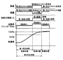
図3は、風路切り換えタイミングの一例を示すタイムチャートである。以下に、同図に示す第1の風路切り換えタイミングを適用した場合における、ドラム式洗濯乾燥機の動作を説明する。 FIG. 3 is a time chart showing an example of air path switching timing. The operation of the drum type washer / dryer when the first air path switching timing shown in the figure is applied will be described below.
乾燥工程において、乾燥運転を開始してから第1所定時間が経過するまでの乾燥序盤期間では、空気通過断面積が大きく圧力損失の少ない第1風路9を使用し、大風量の乾燥用空気をドラム1後方の第1吹出口8から吹き出して衣類に当てる。すなわち、制御部70は、風路切換部12を制御して第1風路9側を開き、乾燥運転を開始する。また、制御部70は、乾燥運転の開始と同時にタイマ71による計時を開始し、第1所定時間が経過するまで第1風路9の開状態を継続する。この場合、第1風路9の圧力損失が少ないため、送風ファン用モータ4bの回転数を比較的低くし、少ない消費電力で送風部4を駆動しても、大風量の風を得ることができる。よって、乾燥序盤における乾燥時間の短縮およびこの間の消費電力量の低減を図れる。
In the drying process, the
そして、乾燥運転を開始してから第1所定時間経過後の乾燥中盤期間および乾燥運転を開始してから第2所定時間が経過した後の乾燥終盤期間においては、風路切換部12によって第2風路11に切り換え、送風ファン用モータ4bの回転数を上げる。衣類は、繊維の種類、布の織り方等々により、脱水終了後の衣類の水分含有量は、大きく異なる。化繊を多く含む衣類の場合は、脱水後の水分含有量すなわち初期乾燥率は、かなり高く90%近いものとなる。このような衣類の場合、乾燥序盤及び乾燥中盤期間に、シワが発生して固着し易い期間を含むが、第2風路の第2吹出口から吹き出される高圧高速の乾燥用空気によって衣類が常時押し広げられるため、シワが低減する。これにより、乾燥中盤期間および乾燥終盤期間では、第1吹出口8よりも空気通過断面積が小さい第2吹出口10から、送風ファン用モータ4bを大回転数で回転させて得られる高圧で高速の乾燥用空気が送風される。すなわち、制御部70は、乾燥運転を開始してから第1所定時間が経過したとき、風路切換部12を制御して第2風路11側を開くとともに、送風部4を制御して送風ファン用モータ4bの回転数を上げる。その後、制御部70は、乾燥工程の終了まで、第2風路11の開状態を継続する。この場合、高圧高速の風によって衣類が常時押し広げられるため、シワが低減する。
Then, in the middle drying period after the first predetermined time has elapsed since the start of the drying operation and the final drying period after the second predetermined time has elapsed since the start of the drying operation, the air
これにより、従来例のように、高圧で高速の乾燥用空気を常に吹き出し、さらに風量を増加するために2つの送風ファン用モータを常に使用するよりも、トータルの消費電力量が少なく、衣類のシワも少ない良好な乾燥仕上がりを実現することができる。 As a result, as in the conventional example, the total amount of power consumption is less than the case where the high-speed and high-speed drying air is always blown out and the two blower fan motors are always used to further increase the air volume. A good dry finish with less wrinkles can be realized.
図4は、風路切り換えタイミングの他の例を示すタイムチャートである。以下に、同図に示す第2の風路切り換えタイミングを適用した場合における、ドラム式洗濯乾燥機の動作を説明する。 FIG. 4 is a time chart showing another example of the airway switching timing. The operation of the drum type washer / dryer when the second air path switching timing shown in the figure is applied will be described below.
乾燥工程において、乾燥運転を開始してから第1所定時間および第2所定時間経過するまでの乾燥序盤期間および乾燥中盤期間においては、第2風路11を使用し、吹出口付近の空気通過断面積が小さい第2吹出口10から、送風ファン用モータ4bを大回転数で回転させて得られる高圧で高速の乾燥用空気を送風して衣類に当てる。すなわち、制御部70は、風路切換部12を制御して第2風路11側を開き、乾燥運転を開始する。また、制御部70は、乾燥運転の開始と同時にタイマ71による計時を開始し、第2所定時間が経過するまで第2風路11の開状態を継続する。この場合、高圧高速の風によって衣類が常時押し広げられるため、シワが低減する。
In the drying process, the
その後、第2所定時間経過後の乾燥終盤には、風路切換部12によって第1風路9に切り換える。乾燥終盤は、衣類に含まれる水分量が少なく、この少ない水分が乾燥用空気と接触して蒸発するには時間がかかる。この様な状態では、大風量の乾燥用空気をドラム1内に送風して水分と乾燥用空気とが接触する機会を多くすることが必要であり、低消費電力で大風量が得られることが望ましい。そこで、空気通過断面積が大きく圧力損失の少ない第1風路9を使用し、大風量の乾燥用空気をドラム1後方の第1吹出口8から吹き出して衣類に当てる。すなわち、制御部70は、乾燥運転を開始してから第2所定時間が経過したとき、風路切換部12を制御して第1風路9側を開くとともに、送風部4を制御して送風ファン用モータ4bの回転数を下げる。その後、制御部70は、乾燥工程の終了まで、第1風路9の開状態を継続する。この場合、第1風路9の圧力損失が少ないため、送風ファン用モータ4bの回転数を比較的低くし、少ない消費電力で送風部4を駆動しても、大風量の風を得ることができる。よって、乾燥終盤における乾燥時間の短縮およびこの間の消費電力量の低減を図れる。
Thereafter, the air
これにより、従来例のように、高圧で高速の乾燥用空気を常に吹き出し、さらに風量を増加するために2つの送風ファン用モータを常に使用するよりも、トータルの消費電力量が少なく、衣類のシワも少ない良好な乾燥仕上がりを実現することができる。 As a result, as in the conventional example, the total amount of power consumption is less than the case where the high-speed and high-speed drying air is always blown out and the two blower fan motors are always used to further increase the air volume. A good dry finish with less wrinkles can be realized.
図5は、風路切り換えタイミングの他の例を示すタイムチャートである。以下に、同図に示す第3の風路切り換えタイミングを適用した場合における、ドラム式洗濯乾燥機の動作を説明する。 FIG. 5 is a time chart showing another example of the air path switching timing. The operation of the drum type washer / dryer when the third air path switching timing shown in FIG.
乾燥工程において、乾燥運転を開始してから第1所定時間が経過するまでの乾燥序盤期間では、空気通過断面積が大きく圧力損失の少ない第1風路9を使用し、大風量の乾燥用空気をドラム1後方の第1吹出口8から吹き出して衣類に当てる。すなわち、制御部70は、風路切換部12を制御して第1風路9側を開き、乾燥運転を開始する。また、制御部70は、乾燥運転の開始と同時にタイマ71による計時を開始し、第1所定時間が経過するまで第1風路9の開状態を継続する。この場合、第1風路9の圧力損失が少ないため、送風ファン用モータ4bの回転数を比較的低くし、少ない消費電力で送風部4を駆動しても、大風量の風を得ることができる。よって、乾燥序盤における乾燥時間の短縮およびこの間の消費電力量の低減を図れる。
In the drying process, the
そして、乾燥運転を開始してから第1所定時間経過後の乾燥中盤期間においては、風路切換部12によって第2風路11に切り換え、送風ファン用モータ4bの回転数を上げる。これにより、乾燥中盤期間では、第1吹出口8よりも空気通過断面積が小さい第2吹出口10から、送風ファン用モータ4bを大回転数で回転させて得られる高圧で高速の乾燥用空気が送風される。すなわち、制御部70は、乾燥運転を開始してから第1所定時間が経過したとき、風路切換部12を制御して第2風路9側を開くとともに、送風部4を制御して送風ファン用モータ4bの回転数を上げる。その後、制御部70は、第2所定時間が経過するまで、第2風路11の開状態を継続する。この場合、高圧高速の風によって衣類が常時押し広げられるため、シワが低減する。
In the middle drying period after the first predetermined time has elapsed since the start of the drying operation, the air
さらに、第2所定時間経過後の乾燥終盤には、風路切換部12によって第1風路9に切り換える。乾燥終盤は、衣類に含まれる水分量が少なく、この少ない水分が乾燥用空気と接触して蒸発するには時間がかかる。この様な状態では、大風量の乾燥用空気をドラム1内に送風して水分と乾燥用空気とが接触する機会を多くすることが必要であり、低消費電力で大風量が得られることが望ましい。そこで、空気通過断面積が大きく圧力損失の少ない第1風路9を使用し、大風量の乾燥用空気をドラム1後方の第1吹出口8から吹き出して衣類に当てる。すなわち、制御部70は、乾燥運転を開始してから第2所定時間が経過したとき、風路切換部12を制御して第1風路9側を開くとともに、送風部4を制御して送風ファン用モータ4bの回転数を下げる。その後、制御部70は、乾燥工程の終了まで、第1風路9の開状態を継続する。この場合、第1風路9の圧力損失が少ないため、送風ファン用モータ4bの回転数を比較的低くし、少ない消費電力で送風部4を駆動しても、大風量の風を得ることができる。よって、乾燥終盤における乾燥時間の短縮およびこの間の消費電力量の低減を図れる。
Further, at the end of drying after the elapse of the second predetermined time, the air
これにより、従来例のように、高圧で高速の乾燥用空気を常に吹き出し、さらに風量を増加するために2つの送風ファン用モータを常に使用するよりも、トータルの消費電力量が少なく、衣類のシワも少ない良好な乾燥仕上がりを実現することができる。 As a result, as in the conventional example, the total amount of power consumption is less than the case where the high-speed and high-speed drying air is always blown out and the two blower fan motors are always used to further increase the air volume. A good dry finish with less wrinkles can be realized.
図6および図7は、風路切り換えタイミングの他の例を示すタイムチャートである。以下に、これらの図に示す第4の風路切り換えタイミングを適用した場合における、ドラム式洗濯乾燥機の動作を説明する。 6 and 7 are time charts showing other examples of the airway switching timing. The operation of the drum type washer / dryer when the fourth air path switching timing shown in these drawings is applied will be described below.
上記のように、制御部70は、乾燥工程開始からの時間(第1所定時間および第2所定時間)に基づいて、乾燥工程における乾燥序盤、乾燥中盤および乾燥終盤の各期間の時期を判断しているが、乾燥対象の衣類の量により、乾燥工程全体の時間および各期間の長さが異なる。そこで、本実施の形態では、布量検知部15により乾燥対象の衣類の量を検知し、その検知結果に応じて、各期間の判断基準である第1所定時間および第2所定時間を変更するようになっている。
As described above, the
布量検知部15は、洗濯開始前に、ドラム1に投入された衣類の量(質量)を検知する。具体的には、布量検知部15は、水槽2が空の状態(水槽2内に水が存在せず、ドラム1に衣類が投入されていない状態)におけるダンパ14の軸の位置と、洗濯開始前であって水を水槽2に注入する前の状態(水槽2内に水は存在しないが、ドラム1内には衣類が存在する状態)におけるダンパ14の軸の位置との差によって、ドラム1に投入された衣類の量を検知する。
The cloth
そして、制御部70は、布量検知部15の検知結果に基づいて、第1所定時間および第2所定時間を設定する。図6は図7よりも乾燥対象の衣類の量が少ない場合を示している。衣類の量が少ない図6において、制御部70は、第1所定時間をA1、第2所定時間をA2に設定している。一方、衣類の量が多い図7において、制御部70は、第1所定時間をB1、第2所定時間をB2に設定している。図7の場合、乾燥工程全体の時間が図6の場合よりも長く、乾燥率が90%や100%に到達するタイミングも図6の場合よりも遅くなる。よって、制御部70は、第1所定時間および第2所定時間を、A1<B1、A2<B2となるように設定する。すなわち、制御部70は、乾燥対象の衣類の量が多いほど、第1所定時間および第2所定時間が長くなるように設定する。
Then, the
このように、乾燥対象の衣類の量に応じて、乾燥序盤、乾燥中盤、乾燥終盤の時間を最適化することにより、乾燥工程において効果的に第1風路9と第2吹出口10とを切り換えることができる。これにより、従来例のように、高圧で高速の乾燥用空気を常に吹き出し、さらに風量を増加するために2つの送風ファン用モータを常に使用するよりも、トータルの消費電力量が少なく、衣類のシワも少ない良好な乾燥仕上がりを実現することができる。
Thus, by optimizing the time of the beginning of drying, the middle of drying, and the end of drying according to the amount of clothes to be dried, the
なお、衣類の量の検知結果に応じて第1所定時間および第2所定時間を変更する構成は、図3ないし図5に示した第1ないし第3の風路切り換えタイミングの何れにも適用できる。 In addition, the structure which changes 1st predetermined time and 2nd predetermined time according to the detection result of the quantity of clothing is applicable to either of the 1st thru | or 3rd air path switching timing shown to FIG. 3 thru | or FIG. .
本実施の形態においては、布量検知部15として、ダンパ14の軸の上下変位量を検知する方式のものを例示したが、これに限定されるものではない。例えば、ドラム1を回転させるドラム駆動モータ3の回転数、駆動電流、トルクなどの変動量を検知し、ドラム駆動モータ3の負荷変動からドラム1内の衣類の量を検知する方式の布量検知部を適用してもよい。
In the present embodiment, the cloth
また、本実施の形態においては、布量検知部15の検知結果に応じて制御部70が第1所定時間および第2所定時間を自動的に変更する構成を示したが、布量検知部15が存在しない場合でも、使用者が入力設定部32から衣類の量を入力し、当該使用者の入力に応じて制御部70が第1所定時間および第2所定時間を変更する構成とすることもできる。
In the present embodiment, the
また、本実施の形態においては、洗濯機能および衣類乾燥機能をともに具備するドラム式洗濯乾燥機について説明したが、本発明はこれに限定されるものではなく、洗濯機能を具備しない衣類乾燥機にも適用できる。衣類乾燥機の構成例としては、図1に示すドラム式洗濯乾燥機から洗濯機能を除いた構成とすることができる。例えば、洗濯機能を具備しない衣類乾燥機としては、図1の水槽2には給水管や排水管40を接続する必要がなく、水槽2を単なるドラム1の外槽として構成し、その他の基本構成を図1のドラム式洗濯乾燥機と同様とすればよい。
Further, in the present embodiment, the drum type washing / drying machine having both the washing function and the clothes drying function has been described. However, the present invention is not limited to this, and the clothes drying machine having no washing function is described. Is also applicable. As an example of the configuration of the clothes dryer, the drum type laundry dryer shown in FIG. For example, as a clothes dryer that does not have a washing function, there is no need to connect a water supply pipe or a
また、本実施の形態においては、本発明をドラム式の洗濯乾燥機に適用した例を説明したが、ドラム式に限定されるものではない。すなわち、本発明の衣類乾燥機および洗濯乾燥機は、送風ファン用モータのトータルの消費電力量を低減し、且つ、乾燥時間を短縮化して、低消費電力量でシワの少ない乾燥を可能とするものであるため、ドラム式以外の吊り干し乾燥やパルセータ方式の縦型洗濯乾燥等の用途にも適応できる。 In the present embodiment, an example in which the present invention is applied to a drum-type washing / drying machine has been described. However, the present invention is not limited to the drum-type. That is, the clothes dryer and the washing dryer according to the present invention reduce the total power consumption of the blower fan motor and shorten the drying time to enable drying with low power consumption and less wrinkles. Therefore, it can also be applied to applications such as hanging-drying other than drum type and vertical washing drying of pulsator type.
本発明に係る衣類乾燥機および洗濯乾燥機は、ドラム式、吊り干し式、パルセータ方式等の様々な衣類乾燥機や洗濯乾燥機に好適に利用することができる。 The clothes dryer and the washing dryer according to the present invention can be suitably used for various clothes dryers and washing dryers such as a drum type, a hanging drying type, and a pulsator type.
1 ドラム(収容部)
2 水槽
3 ドラム駆動モータ(ドラム駆動部)
4 送風部
5 排出口
6 除湿部
7 加熱部
8 第1吹出口
9 第1風路
10 第2吹出口
11 第2風路
12 風路切換部
13 循環風路
15 布量検知部
50 ヒートポンプ装置
70 制御部
1 drum (container)
2
DESCRIPTION OF
Claims (10)
前記収容部に開口した第1吹出口を有する第1風路と、
前記第1吹出口よりも空気通過断面積が小さい第2吹出口を有する第2風路と、
前記第1風路と前記第2風路とを選択的に切り換える風路切換部と、
前記第1風路が選択されているときには前記第2風路が選択されているときよりも大風量の乾燥用空気が前記第1吹出口から前記収容部内へ吹き出される一方、前記第2風路が選択されているときには前記第1風路が選択されているときよりも高圧高速の乾燥用空気が前記第2吹出口から前記収容部内へ吹き出されるように乾燥用空気を送風する送風部と、
乾燥工程の途中で、前記第1風路と前記第2風路とが選択的に切り換えられるように前記風路切換部を制御する制御部と、を備え、
前記第1風路は、前記収容部の後方に開口し、
前記第2風路は、前記収容部の前方に開口することを特徴とする衣類乾燥機。 A storage section for storing clothes to be dried;
A first air passage having a first outlet opening in the accommodating portion;
A second air passage having a second air outlet having a smaller air passage cross-sectional area than the first air outlet;
An air path switching unit that selectively switches between the first air path and the second air path;
While drying air large volume than when the second air passage is selected is blown into said receptacle from said first outlet when said first air passage is selected, the second wind blowing unit when the road is selected for blowing drying air to the drying air of the high pressure high speed is blown into the accommodating portion from the second air outlet than when the first air passage is selected When,
In the course of the drying process, Bei example a control unit for the and the first air passage and the second air passage for controlling the air path switching unit so as to be selectively switched,
The first air passage opens behind the housing portion,
The clothes dryer according to claim 2, wherein the second air passage opens in front of the housing portion .
前記制御部は、前記布量検知部が検知する前記衣類の前記量に応じて前記第1所定時間または前記第2所定時間を設定することを特徴とする請求項5に記載の衣類乾燥機。 A cloth amount detection unit for detecting the amount of the clothing in the storage unit;
The clothes dryer according to claim 5 , wherein the control unit sets the first predetermined time or the second predetermined time according to the amount of the clothing detected by the cloth amount detection unit .
前記ドラムを回転駆動するドラム駆動部と、
前記ドラムから排出された多湿状態の前記乾燥用空気を除湿する除湿部と、
前記除湿部で除湿された前記乾燥用空気を加熱する加熱部と、
前記送風部及び前記風路切換部が途中に配設され、前記乾燥用空気を前記ドラム、前記除湿部及び前記加熱部を経て、前記第1吹出口又は前記第2吹出口から、再度、前記ドラムへと順に循環させる循環風路と、をさらに備えていることを特徴とする請求項1乃至7の何れか1項に記載の衣類乾燥機。 The accommodating portion is a cylindrical drum,
A drum drive for rotating the drum;
A dehumidifying unit for dehumidifying the drying air discharged from the drum in a humid state;
A heating unit for heating the drying air dehumidified by the dehumidifying unit;
The air blowing unit and the air path switching unit are arranged in the middle, and the drying air passes through the drum, the dehumidifying unit, and the heating unit, and again from the first air outlet or the second air outlet, The clothes dryer according to any one of claims 1 to 7, further comprising a circulation air path that circulates sequentially to the drum .
前記収容部を内包して洗濯水を貯留する水槽と、を含むことを特徴とする洗濯乾燥機。A washing / drying machine comprising: a water tank that encloses the housing portion and stores washing water.
Priority Applications (6)
| Application Number | Priority Date | Filing Date | Title |
|---|---|---|---|
| JP2009238909A JP5443119B2 (en) | 2009-10-16 | 2009-10-16 | Clothes dryer and washing dryer |
| US13/392,767 US20120159808A1 (en) | 2009-10-16 | 2010-10-08 | Laundry dryer and washer dryer |
| CN201080038448.2A CN102482839B (en) | 2009-10-16 | 2010-10-08 | Clothing dryer and washer dryer |
| PCT/JP2010/006033 WO2011045914A1 (en) | 2009-10-16 | 2010-10-08 | Clothing dryer and washer dryer |
| EP10823182.0A EP2489776B1 (en) | 2009-10-16 | 2010-10-08 | Clothing dryer and washer dryer |
| TW099134875A TW201131043A (en) | 2009-10-16 | 2010-10-13 | Garment dryer, and washing and drying machine |
Applications Claiming Priority (1)
| Application Number | Priority Date | Filing Date | Title |
|---|---|---|---|
| JP2009238909A JP5443119B2 (en) | 2009-10-16 | 2009-10-16 | Clothes dryer and washing dryer |
Publications (3)
| Publication Number | Publication Date |
|---|---|
| JP2011083457A JP2011083457A (en) | 2011-04-28 |
| JP2011083457A5 JP2011083457A5 (en) | 2013-02-07 |
| JP5443119B2 true JP5443119B2 (en) | 2014-03-19 |
Family
ID=43875970
Family Applications (1)
| Application Number | Title | Priority Date | Filing Date |
|---|---|---|---|
| JP2009238909A Active JP5443119B2 (en) | 2009-10-16 | 2009-10-16 | Clothes dryer and washing dryer |
Country Status (6)
| Country | Link |
|---|---|
| US (1) | US20120159808A1 (en) |
| EP (1) | EP2489776B1 (en) |
| JP (1) | JP5443119B2 (en) |
| CN (1) | CN102482839B (en) |
| TW (1) | TW201131043A (en) |
| WO (1) | WO2011045914A1 (en) |
Families Citing this family (14)
| Publication number | Priority date | Publication date | Assignee | Title |
|---|---|---|---|---|
| JP5567978B2 (en) * | 2010-10-21 | 2014-08-06 | パナソニック株式会社 | Clothes dryer and washing dryer |
| JP2013009904A (en) * | 2011-06-30 | 2013-01-17 | Toshiba Corp | Clothing drying machine |
| JP5793652B2 (en) * | 2011-09-02 | 2015-10-14 | パナソニックIpマネジメント株式会社 | Clothes dryer and washing dryer |
| JP6943716B2 (en) * | 2011-12-09 | 2021-10-06 | 東芝ライフスタイル株式会社 | Clothes dryer |
| JP6282389B2 (en) * | 2011-12-09 | 2018-02-21 | 東芝ライフスタイル株式会社 | Clothes dryer |
| JP2014014529A (en) * | 2012-07-10 | 2014-01-30 | Hitachi Appliances Inc | Drum type dryer |
| JP2015171521A (en) * | 2014-02-21 | 2015-10-01 | ハイアールアジア株式会社 | dryer |
| JP6710858B2 (en) * | 2014-08-01 | 2020-06-17 | 青島海爾滾筒洗衣机有限公司 | Drum type washer/dryer and method for drying clothes |
| US10934657B2 (en) * | 2017-03-16 | 2021-03-02 | Panasonic Intellectual Property Management Co., Ltd. | Washer dryer machine and control method |
| CN109402984B (en) * | 2017-08-18 | 2022-04-19 | 青岛海尔滚筒洗衣机有限公司 | Clothes treating device |
| CN109402990B (en) * | 2017-08-18 | 2022-04-22 | 青岛海尔滚筒洗衣机有限公司 | Clothes processing method and clothes processing device |
| CN108677492A (en) * | 2018-05-21 | 2018-10-19 | 无锡小天鹅股份有限公司 | Device for clothing processing with clothes drying function |
| KR20210023034A (en) * | 2019-08-21 | 2021-03-04 | 엘지전자 주식회사 | Drying method using intelligent washing machine and apparatus therefor |
| CN112760898B (en) * | 2020-12-25 | 2021-11-16 | 珠海格力电器股份有限公司 | Washing machine and dewatering method thereof |
Family Cites Families (22)
| Publication number | Priority date | Publication date | Assignee | Title |
|---|---|---|---|---|
| US1675076A (en) * | 1925-05-20 | 1928-06-26 | Peter E Wurfflein | Drying process and apparatus |
| US2961776A (en) * | 1958-09-26 | 1960-11-29 | Gen Electric | Clothes dryer with reversible blower |
| US3921308A (en) * | 1973-11-23 | 1975-11-25 | Challenge Cook Bros Inc | Methods for treating yarn bundles |
| US4006534A (en) * | 1975-08-22 | 1977-02-08 | Norman Dryer Co., Inc. | Variable air supply for fabric dryers |
| US4125945A (en) * | 1977-05-18 | 1978-11-21 | Westlake Agricultural Engineering, Inc. | Multiple stage grain dryer with intermediate steeping |
| JPS60174194A (en) * | 1984-02-20 | 1985-09-07 | 三洋電機株式会社 | Controller of clothing dryer |
| DE4306217B4 (en) * | 1993-02-27 | 2004-04-22 | AEG Hausgeräte GmbH | Program-controlled tumble dryer with a heat pump circuit |
| US6889399B2 (en) * | 2000-07-25 | 2005-05-10 | Steiner-Atlantic Corp. | Textile cleaning processes and apparatus |
| US20060254082A1 (en) * | 2002-11-22 | 2006-11-16 | Kim Su H | Fast clothes dryer and drying method |
| US20060048405A1 (en) * | 2003-05-23 | 2006-03-09 | Baek Seung M | Drum type washing machine and dryer and method for automatic drying by using the same |
| JP4444016B2 (en) * | 2004-06-17 | 2010-03-31 | パナソニック株式会社 | Clothes dryer |
| JP2006197963A (en) * | 2005-01-18 | 2006-08-03 | Toshiba Corp | Drum type washing/drying machine |
| KR100697083B1 (en) * | 2005-04-06 | 2007-03-20 | 엘지전자 주식회사 | Washing machine with dryer |
| JP4783125B2 (en) * | 2005-11-17 | 2011-09-28 | 株式会社東芝 | Clothes dryer |
| KR101253151B1 (en) * | 2006-04-17 | 2013-04-10 | 엘지전자 주식회사 | fire detecting methode of clothes drier |
| JP2008067742A (en) * | 2006-09-12 | 2008-03-27 | Matsushita Electric Ind Co Ltd | Clothes dryer |
| JP5033560B2 (en) * | 2007-09-25 | 2012-09-26 | 日立アプライアンス株式会社 | Washing and drying machine |
| JP4852505B2 (en) * | 2007-09-25 | 2012-01-11 | 日立アプライアンス株式会社 | Dryer and washing dryer |
| JP2009082577A (en) * | 2007-10-02 | 2009-04-23 | Hitachi Appliances Inc | Drying machine, and washing and drying machine |
| US7992321B2 (en) * | 2007-12-19 | 2011-08-09 | Electrolux Home Products | Laundry dryer having three roller drum support system and reversing idler assembly |
| KR101455774B1 (en) * | 2008-04-02 | 2014-11-04 | 삼성전자 주식회사 | Dryer and method of controlling cleaning operation thereof |
| JP5108800B2 (en) * | 2009-01-29 | 2012-12-26 | 日立アプライアンス株式会社 | Laundry dryer and dryer |
-
2009
- 2009-10-16 JP JP2009238909A patent/JP5443119B2/en active Active
-
2010
- 2010-10-08 EP EP10823182.0A patent/EP2489776B1/en active Active
- 2010-10-08 US US13/392,767 patent/US20120159808A1/en not_active Abandoned
- 2010-10-08 CN CN201080038448.2A patent/CN102482839B/en active Active
- 2010-10-08 WO PCT/JP2010/006033 patent/WO2011045914A1/en active Application Filing
- 2010-10-13 TW TW099134875A patent/TW201131043A/en unknown
Also Published As
| Publication number | Publication date |
|---|---|
| EP2489776A4 (en) | 2014-05-14 |
| CN102482839A (en) | 2012-05-30 |
| CN102482839B (en) | 2015-05-06 |
| JP2011083457A (en) | 2011-04-28 |
| WO2011045914A1 (en) | 2011-04-21 |
| EP2489776B1 (en) | 2016-03-09 |
| TW201131043A (en) | 2011-09-16 |
| EP2489776A1 (en) | 2012-08-22 |
| US20120159808A1 (en) | 2012-06-28 |
Similar Documents
| Publication | Publication Date | Title |
|---|---|---|
| JP5443119B2 (en) | Clothes dryer and washing dryer | |
| JP5443120B2 (en) | Clothes dryer and washing dryer | |
| JP5824639B2 (en) | Clothes dryer and washing dryer | |
| EP2602382B1 (en) | Clothes dryer and washer/dryer | |
| JP2011083457A5 (en) | ||
| JP5891364B2 (en) | Clothes dryer and washing dryer | |
| JP2011244979A (en) | Clothes dryer | |
| JP5567978B2 (en) | Clothes dryer and washing dryer | |
| JP6460308B2 (en) | Washing and drying machine | |
| JP5397155B2 (en) | Clothes dryer | |
| JP2011101670A (en) | Clothes drying machine | |
| JP5488397B2 (en) | Washing and drying machine | |
| JP2011206139A (en) | Clothes dryer | |
| JP6910771B2 (en) | Clothes dryer | |
| JP2011083458A (en) | Clothes drying machine and washing and drying machine | |
| JP2011092248A (en) | Clothes dryer and washer/dryer | |
| JP2011101669A (en) | Washing/drying machine | |
| JP2011083456A (en) | Clothes drying machine and washing and drying machine |
Legal Events
| Date | Code | Title | Description |
|---|---|---|---|
| A621 | Written request for application examination |
Free format text: JAPANESE INTERMEDIATE CODE: A621 Effective date: 20121016 |
|
| A521 | Written amendment |
Free format text: JAPANESE INTERMEDIATE CODE: A523 Effective date: 20121214 |
|
| A131 | Notification of reasons for refusal |
Free format text: JAPANESE INTERMEDIATE CODE: A131 Effective date: 20130910 |
|
| A521 | Written amendment |
Free format text: JAPANESE INTERMEDIATE CODE: A523 Effective date: 20131108 |
|
| TRDD | Decision of grant or rejection written | ||
| A01 | Written decision to grant a patent or to grant a registration (utility model) |
Free format text: JAPANESE INTERMEDIATE CODE: A01 Effective date: 20131203 |
|
| A61 | First payment of annual fees (during grant procedure) |
Free format text: JAPANESE INTERMEDIATE CODE: A61 Effective date: 20131219 |
|
| R150 | Certificate of patent or registration of utility model |
Ref document number: 5443119 Country of ref document: JP Free format text: JAPANESE INTERMEDIATE CODE: R150 Free format text: JAPANESE INTERMEDIATE CODE: R150 |