JP5438327B2 - Measuring device using terahertz waves - Google Patents
Measuring device using terahertz waves Download PDFInfo
- Publication number
- JP5438327B2 JP5438327B2 JP2009012454A JP2009012454A JP5438327B2 JP 5438327 B2 JP5438327 B2 JP 5438327B2 JP 2009012454 A JP2009012454 A JP 2009012454A JP 2009012454 A JP2009012454 A JP 2009012454A JP 5438327 B2 JP5438327 B2 JP 5438327B2
- Authority
- JP
- Japan
- Prior art keywords
- unit
- integration
- frequency
- time
- signal
- Prior art date
- Legal status (The legal status is an assumption and is not a legal conclusion. Google has not performed a legal analysis and makes no representation as to the accuracy of the status listed.)
- Expired - Fee Related
Links
- 230000010354 integration Effects 0.000 claims description 85
- 238000001514 detection method Methods 0.000 claims description 82
- 238000005259 measurement Methods 0.000 claims description 57
- 238000000034 method Methods 0.000 claims description 43
- 238000012545 processing Methods 0.000 claims description 24
- 238000012935 Averaging Methods 0.000 claims description 20
- 238000000691 measurement method Methods 0.000 claims description 8
- 238000004611 spectroscopical analysis Methods 0.000 claims description 6
- 230000036961 partial effect Effects 0.000 claims description 3
- 230000003287 optical effect Effects 0.000 description 26
- 230000005684 electric field Effects 0.000 description 17
- 238000001228 spectrum Methods 0.000 description 14
- 230000000694 effects Effects 0.000 description 9
- 230000002829 reductive effect Effects 0.000 description 9
- 230000002238 attenuated effect Effects 0.000 description 5
- 238000010586 diagram Methods 0.000 description 4
- 230000008569 process Effects 0.000 description 4
- 239000013078 crystal Substances 0.000 description 3
- 230000003247 decreasing effect Effects 0.000 description 3
- 238000001914 filtration Methods 0.000 description 3
- 239000004065 semiconductor Substances 0.000 description 3
- 229910001218 Gallium arsenide Inorganic materials 0.000 description 2
- 230000009102 absorption Effects 0.000 description 2
- 238000010521 absorption reaction Methods 0.000 description 2
- 230000003321 amplification Effects 0.000 description 2
- 238000013459 approach Methods 0.000 description 2
- 239000003990 capacitor Substances 0.000 description 2
- 239000000969 carrier Substances 0.000 description 2
- 230000008859 change Effects 0.000 description 2
- 238000006243 chemical reaction Methods 0.000 description 2
- 230000007423 decrease Effects 0.000 description 2
- 238000005516 engineering process Methods 0.000 description 2
- 239000000284 extract Substances 0.000 description 2
- 230000001678 irradiating effect Effects 0.000 description 2
- 238000003199 nucleic acid amplification method Methods 0.000 description 2
- 230000000704 physical effect Effects 0.000 description 2
- 230000009467 reduction Effects 0.000 description 2
- 239000000126 substance Substances 0.000 description 2
- JBRZTFJDHDCESZ-UHFFFAOYSA-N AsGa Chemical compound [As]#[Ga] JBRZTFJDHDCESZ-UHFFFAOYSA-N 0.000 description 1
- RTAQQCXQSZGOHL-UHFFFAOYSA-N Titanium Chemical compound [Ti] RTAQQCXQSZGOHL-UHFFFAOYSA-N 0.000 description 1
- 230000008901 benefit Effects 0.000 description 1
- 238000004891 communication Methods 0.000 description 1
- 230000003111 delayed effect Effects 0.000 description 1
- 230000001066 destructive effect Effects 0.000 description 1
- 230000006866 deterioration Effects 0.000 description 1
- 239000010408 film Substances 0.000 description 1
- 238000003384 imaging method Methods 0.000 description 1
- 230000006872 improvement Effects 0.000 description 1
- 238000007689 inspection Methods 0.000 description 1
- 230000000670 limiting effect Effects 0.000 description 1
- 229910052751 metal Inorganic materials 0.000 description 1
- 239000002184 metal Substances 0.000 description 1
- 229910052757 nitrogen Inorganic materials 0.000 description 1
- IJGRMHOSHXDMSA-UHFFFAOYSA-N nitrogen Substances N#N IJGRMHOSHXDMSA-UHFFFAOYSA-N 0.000 description 1
- QJGQUHMNIGDVPM-UHFFFAOYSA-N nitrogen group Chemical group [N] QJGQUHMNIGDVPM-UHFFFAOYSA-N 0.000 description 1
- 230000001902 propagating effect Effects 0.000 description 1
- 230000000630 rising effect Effects 0.000 description 1
- 229920006395 saturated elastomer Polymers 0.000 description 1
- 230000035945 sensitivity Effects 0.000 description 1
- 238000004904 shortening Methods 0.000 description 1
- 230000001629 suppression Effects 0.000 description 1
- 230000001360 synchronised effect Effects 0.000 description 1
- 239000010409 thin film Substances 0.000 description 1
- 239000010936 titanium Substances 0.000 description 1
- 229910052719 titanium Inorganic materials 0.000 description 1
- 230000001131 transforming effect Effects 0.000 description 1
- 230000007704 transition Effects 0.000 description 1
- 238000002834 transmittance Methods 0.000 description 1
Images


Classifications
-
- G—PHYSICS
- G01—MEASURING; TESTING
- G01J—MEASUREMENT OF INTENSITY, VELOCITY, SPECTRAL CONTENT, POLARISATION, PHASE OR PULSE CHARACTERISTICS OF INFRARED, VISIBLE OR ULTRAVIOLET LIGHT; COLORIMETRY; RADIATION PYROMETRY
- G01J3/00—Spectrometry; Spectrophotometry; Monochromators; Measuring colours
- G01J3/28—Investigating the spectrum
- G01J3/42—Absorption spectrometry; Double beam spectrometry; Flicker spectrometry; Reflection spectrometry
Description
本発明は、時間領域でのテラヘルツ波を測定する装置(THz-TDS装置、THz-Time Domain Spectroscopy 装置)の測定システムの技術に関する。 The present invention relates to a technique of a measurement system of a device (THz-TDS device, THz-Time Domain Spectroscopy device) that measures terahertz waves in the time domain.
テラヘルツ波は、0.03THzから30THzのうち、任意の周波数帯域を有する電磁波である。このような周波数帯域には、生体分子をはじめとして、様々な物質の構造や状態に由来する特徴的な吸収が多く存在する。このような特徴を活かして、非破壊にて物質の分析や同定を行う検査技術が開発されている。また、X線に替わる安全なイメージング技術や、高速な通信技術への応用が期待されている。 The terahertz wave is an electromagnetic wave having an arbitrary frequency band from 0.03 THz to 30 THz. In such a frequency band, there are many characteristic absorptions derived from structures and states of various substances including biomolecules. Taking advantage of these features, inspection techniques have been developed to analyze and identify substances in a non-destructive manner. In addition, it is expected to be applied to safe imaging technology that replaces X-rays and high-speed communication technology.
THz-TDS装置は、超短パルスによって、検出器に到達するテラヘルツ波の瞬間的な電界強度を取得する。そして、この超短パルスが検出器に到達するタイミングを変化させることによって生ずる瞬間的な電界強度の変化を記録し、本装置は、テラヘルツ波の時間波形を取得する。つまり、本装置では、超短パルスによって、検出器に到達するテラヘルツ波をサンプリング計測している。上述した特徴的な吸収を測定する場合は、この時間波形を周波数領域の情報に変換し、周波数スペクトルを取得する。 The THz-TDS device acquires the instantaneous electric field strength of the terahertz wave that reaches the detector by an ultrashort pulse. And the change of the instantaneous electric field strength which arises by changing the timing when this ultrashort pulse arrives at a detector is recorded, and this device acquires the time waveform of a terahertz wave. That is, in this apparatus, the terahertz wave reaching the detector is sampled and measured by an ultrashort pulse. When measuring the characteristic absorption described above, this time waveform is converted into information in the frequency domain, and a frequency spectrum is acquired.
多くの場合、この電界強度に相当する信号強度は微弱であるため、ロックインアンプに代表される微小信号測定器(本発明では微小信号検出部とも呼ぶ)によって信号を取得する。THz-TDS装置で、ロックインアンプによる信号検出を行う場合、テラヘルツ波は周波数fsで変調され、ロックインアンプはこの周波数fsの成分を検出する。この検出された信号をテラヘルツ波の瞬間的な電界強度としている。この時、ロックインアンプは、変調された電界強度の信号に対し、変調周波数fsと同じ周波数を有する参照信号によって乗算する。そして、ロックインアンプは、派生した和(2fs)と差(直流成分)の周波数成分のうち、差の周波数成分をフィルタで取り出す。 In many cases, since the signal intensity corresponding to the electric field intensity is weak, a signal is acquired by a minute signal measuring device represented by a lock-in amplifier (also referred to as a minute signal detector in the present invention). When signal detection by a lock-in amplifier is performed with a THz-TDS device, the terahertz wave is modulated at a frequency fs, and the lock-in amplifier detects a component of this frequency fs. This detected signal is the instantaneous electric field strength of the terahertz wave. At this time, the lock-in amplifier multiplies the modulated signal strength signal by a reference signal having the same frequency as the modulation frequency fs. Then, the lock-in amplifier extracts the difference frequency component from the derived sum (2 fs) and difference (DC component) frequency components using a filter.
このような微小信号測定器によって測定される信号には、上述した電界強度に関する信号について、超短パルスの強度変動の影響や、測定システムが発する信号(熱雑音やシステム固有のノイズなど)が重畳されている。この結果、テラヘルツ波の時間波形を構築する際、図9のように、取得したい信号に対して各測定データがばらついてしまうことがある。このような信号ばらつきは、例えば、テラヘルツ波の時間波形を周波数領域の情報に変換する際、ノイズフロアを上昇させる一因となる。このノイズフロアの上昇は、測定帯域を制限するため、不要な信号成分の抑制が求められている。 The signal measured by such a minute signal measuring device is superimposed with the signal related to the electric field strength described above, the influence of the intensity fluctuation of the ultrashort pulse, and the signal generated by the measurement system (thermal noise, system-specific noise, etc.). Has been. As a result, when the time waveform of the terahertz wave is constructed, each measurement data may vary with respect to the signal to be acquired as shown in FIG. Such signal variation is a cause of increasing the noise floor when, for example, converting a time waveform of a terahertz wave into information in the frequency domain. Since this increase in noise floor limits the measurement band, suppression of unnecessary signal components is required.
この対策の一つとして、複数のテラヘルツ波の時間波形に対して加算平均処理を行う手法がある。例えば、上記超短パルスが検出器に到達するタイミングを細かくし、1回の時間波形から複数の時間波形を構築し、これを加算平均処理する手法が提案されている(特許文献1)。
上述したように、複数のテラヘルツ波の時間波形を加算平均する手法は、テラヘルツ波の測定回数分だけ測定時間が長くなる。上記特許文献1はこれを改善するための一手法を開示している。
As described above, the method of adding and averaging the time waveforms of a plurality of terahertz waves increases the measurement time by the number of times of terahertz wave measurement.
上記特許文献1は、超短パルスが検出器に到達するタイミングを機械ステージによって制御している。具体的には、機械ステージ上に折り返し光学系を配置し、超短パルスが伝搬する光路長を調整している(遅延光学系とも呼ばれる)。テラヘルツ波の時間波形を構成する測定点間の間隔は、周波数領域の最高周波数に相当する。例えば、数10THzの領域のスペクトルを得たい場合、機械ステージは数μmの精度で制御する。そして、テラヘルツ波の時間波形を取得する際、この位置決め精度で、機械ステージを数mmの範囲で動かして測定を行う。テラヘルツ波の測定時間は、主に、この遅延光学系を動かす速度に依存する。
In
特許文献1は、この測定点間の間隔を更に短くした状態で機械ステージを動かすものである。しかし、機械ステージは、より細かい位置決め精度を要求されるので、テラヘルツ波の時間波形を高速に取得するために、この細かい位置決め精度を維持しながら機械ステージを高速に長距離動かすことは容易ではない。
In
また、ロックインアンプは、この機械ステージを高速に動かしたことに伴う信号変化に対応できるだけの時定数を有する必要がある。具体的には、時定数は小さくする方向に調整する。ところが、変調周波数fsと機械ステージの速度によっては、時定数を小さくすることによって、時定数が和(2fs)の周波数成分に近づくことがある。その結果、この周波数成分付近の信号を十分減衰することができずに周波数領域のノイズフロアが上がってしまうことが懸念される。例えば、図6(b)において、微小信号検出部の周波数特性は上述した時定数に依るが、この周波数特性が2fsの成分に近づくと、この成分を十分減衰させることは難しくなる。この結果、例えば図5(b)のように、微小信号検出部から出力される信号は、ばらつきが大きくなり、ノイズフロアが上がることによって周波数スペクトルの測定帯域を制限する。これは、元来、直流成分を取得する用途のロックインアンプを用いてテラヘルツ波の時間波形を高速に取得する際、周波数スペクトルを取得するため、高速測定と共に信号の安定性の両立が求められるという、テラヘルツ波測定における特有の課題ともいえる。 Further, the lock-in amplifier needs to have a time constant that can cope with a signal change caused by moving the mechanical stage at high speed. Specifically, the time constant is adjusted in the direction of decreasing. However, depending on the modulation frequency fs and the speed of the mechanical stage, the time constant may approach the frequency component of the sum (2 fs) by reducing the time constant. As a result, there is a concern that the signal near the frequency component cannot be sufficiently attenuated and the noise floor in the frequency domain is raised. For example, in FIG. 6B, the frequency characteristic of the minute signal detection unit depends on the time constant described above, but when this frequency characteristic approaches a component of 2 fs, it is difficult to sufficiently attenuate this component. As a result, for example, as shown in FIG. 5B, the signal output from the minute signal detection unit is highly varied, and the noise floor is increased, thereby limiting the frequency spectrum measurement band. Originally, when acquiring a terahertz time waveform at high speed using a lock-in amplifier for acquiring a direct current component, a frequency spectrum is acquired, so that both high-speed measurement and signal stability are required. It can be said that this is a unique problem in terahertz wave measurement.
このように、テラヘルツ波の測定においては、ノイズフロアを下げつつ測定時間を短縮することが潜在的に求められている。 Thus, in measuring terahertz waves, it is potentially required to reduce the measurement time while lowering the noise floor.
上記課題に鑑み、本発明の測定装置は、時間領域分光法によってテラヘルツ波パルスの時間波形を取得する測定装置であって、検出部と、微小信号検出部と、積分部と、処理部を有する。前記検出部は、周波数fsの信号成分を含むテラヘルツ波パルスを検出する。微小信号検出部は、時定数τを有し、前記検出部からの信号から周波数fsの信号成分を検出する。前記積分部は、前記微小信号検出部の出力段に接続され、その時定数は、時定数τ以下で、かつ1/(2fs)より大きい特性である。処理部は、取り込み間隔Δtで積分部からデータを取り込みテラヘルツ波パルスの時間波形を構築する。時定数τは取り込み間隔Δt以下である。 In view of the above problems, the measurement apparatus of the present invention is a measurement apparatus that acquires a time waveform of a terahertz wave pulse by time domain spectroscopy, and includes a detection unit, a minute signal detection unit, an integration unit, and a processing unit . . The detection unit detects a terahertz wave pulse including a signal component having a frequency fs. The minute signal detection unit has a time constant τ and detects a signal component having a frequency fs from the signal from the detection unit. The integration unit is connected to the output stage of the minute signal detection unit, and its time constant is a characteristic that is less than the time constant τ and greater than 1 / (2fs). The processing unit captures data from the integration unit at the capturing interval Δt and constructs a time waveform of the terahertz wave pulse. The time constant τ is not more than the capture interval Δt.
また、本発明における測定方法は、時間領域分光法によってテラヘルツ波パルスの時間波形を取得する測定方法であって、検出ステップと、微小信号検出ステップと、積分ステップと、処理ステップを有する。検出ステップは、周波数fsの信号成分を含むテラヘルツ波パルスを検出する。微小信号検出ステップは、時定数τを有し、前記検出ステップで検出される信号から周波数fsの信号成分を検出する。積分ステップは、前記微小信号検出ステップで検出される信号を積算し、その時定数は、時定数τ以下で、かつ1/(2fs)より大きい特性である。処理ステップは、取り込み間隔Δtで、積分ステップにおいて生成されたデータを取り込みテラヘルツ波パルスの時間波形を構築する。時定数τは取り込み間隔Δt以下である。 The measurement method according to the present invention is a measurement method for acquiring a time waveform of a terahertz wave pulse by time domain spectroscopy, and includes a detection step, a minute signal detection step, an integration step, and a processing step . In the detection step, a terahertz wave pulse including a signal component having a frequency fs is detected. The minute signal detection step has a time constant τ and detects a signal component of the frequency fs from the signal detected in the detection step. The integration step integrates the signals detected in the minute signal detection step, and the time constant is a characteristic that is less than the time constant τ and greater than 1 / (2fs). The processing step captures the data generated in the integration step at the capture interval Δt and constructs a time waveform of the terahertz wave pulse. The time constant τ is not more than the capture interval Δt.
本発明のテラヘルツ波測定装置及び方法によれば、少なくとも微小信号検出部ないしステップが有する時定数τよりも小さな時定数を有する積分部ないしステップによって、時間波形の信号ばらつきに寄与していた成分の信号を減衰させる。また、微小信号検出部ないしステップが有する時定数よりも小さな時定数を有する積分部ないしステップを用いることで、測定システム全体の時定数に与える影響を小さくする。このことから、測定時間を増やすことなくノイズフロアの低減ができ、測定帯域が広がるという効果を奏する。 According to the terahertz wave measuring apparatus and method of the present invention, the component contributing to the signal variation of the time waveform by at least the integrating unit or step having a time constant smaller than the time constant τ of the minute signal detecting unit or step. Attenuate the signal. Further, by using an integration unit or step having a time constant smaller than that of the minute signal detection unit or step, the influence on the time constant of the entire measurement system is reduced. As a result, the noise floor can be reduced without increasing the measurement time, and the measurement band can be widened.
本発明の実施の形態について説明する。
本発明の装置及び方法において重要なことは、次の点である。時定数τを有し、周波数fsの信号成分を検出する微小信号検出部ないしステップの出力段に接続される積分部ないしステップの時定数が、時定数τ以下で、かつ1/(2fs)より大きい特性であることである。このことより、時間波形の信号ばらつきに寄与していた成分の信号を減衰させると共に、測定システム全体の時定数に与える影響を小さくできる。更に、周波数成分2fs以降の周波数成分を減衰させることもできる。
Embodiments of the present invention will be described.
The following points are important in the apparatus and method of the present invention. The time constant of the integration unit or step connected to the output stage of the minute signal detection unit or step having the time constant τ and detecting the signal component of the frequency fs is less than the time constant τ and from 1 / (2 fs) It is a great characteristic. Thus, the signal of the component that has contributed to the signal variation in the time waveform can be attenuated and the influence on the time constant of the entire measurement system can be reduced. Furthermore, frequency components after the frequency component 2fs can be attenuated.
上記考え方に基づき、本発明の装置及び方法の基本的な実施形態は、次の様な構成を有する。時間領域分光法によってテラヘルツ波パルスの時間波形を取得する測定装置ないし方法において、時定数τを有し、周波数fsの信号成分を検出する微小信号検出部ないしステップの出力段に接続される積分部ないしステップを有する。そして、積分部ないしステップの時定数は、時定数τ以下で、かつ1/(2fs)より大きい。 Based on the above concept, the basic embodiment of the apparatus and method of the present invention has the following configuration. In a measuring apparatus or method for acquiring a time waveform of a terahertz wave pulse by time domain spectroscopy, a minute signal detector having a time constant τ and detecting a signal component of frequency fs or an integrator connected to an output stage of a step Or has steps. The time constant of the integration unit or step is less than the time constant τ and greater than 1 / (2fs).
前記基本的な実施形態において、以下に述べる様なより具体的な実施形態が可能である。
前記積分部ないしステップの出力段に接続され、前記時間波形を構成するデータ毎に加算平均を行う加算平均回路ないしステップを更に備えることができる(図4の構成例を参照)。この構成によれば、積分部ないしステップの出力について回路的に複数分岐させ、各分岐させた信号の加算平均を求める。この結果、ランダムに発生する熱的な雑音を抑制することができるので、ノイズフロアの低減ができるという効果を奏する。
In the basic embodiment, more specific embodiments as described below are possible.
An addition averaging circuit or step connected to the integration unit or the output stage of the step and performing addition averaging for each data constituting the time waveform can be further provided (see the configuration example in FIG. 4). According to this configuration, the integration unit or the output of the step is divided into a plurality of circuits in terms of circuit, and the addition average of the branched signals is obtained. As a result, it is possible to suppress thermal noise that is randomly generated, so that the noise floor can be reduced.
また、前記時間波形を複数取得し、これらの波形の加算平均を行う波形の加算平均ステップを更に備えることができる(ラピッドスキャンの適用)。これによれば、ノイズフロアを低減した状態で、テラヘルツ波の波形の加算平均を求めている。そのため、従来の測定方法に比べ、同程度のSN比を得るために必要な時間波形の測定回数を減らすことができ、測定時間の高速化を容易にするという効果を奏する。 In addition, it is possible to further include a waveform averaging step of acquiring a plurality of the time waveforms and performing an averaging of these waveforms (application of rapid scan). According to this, the addition average of the terahertz wave waveforms is obtained in a state where the noise floor is reduced. Therefore, compared with the conventional measurement method, the number of time waveform measurements required to obtain the same S / N ratio can be reduced, and the effect of facilitating the speeding up of the measurement time can be achieved.
以下、本発明の思想を実施し得る実施形態について、図面を参照して説明する。
図1は、本発明のテラヘルツ波測定装置及び方法の一実施形態に関する概略構成図である。図1によると、テラヘルツ波測定装置は、テラヘルツ波の瞬間的な電界強度を測定する測定部101、測定部101の出力よりテラヘルツ波パルスの時間波形を構築する部分に大別される。
DESCRIPTION OF EMBODIMENTS Hereinafter, embodiments capable of implementing the idea of the present invention will be described with reference to the drawings.
FIG. 1 is a schematic configuration diagram relating to an embodiment of the terahertz wave measuring apparatus and method of the present invention. According to FIG. 1, the terahertz wave measuring apparatus is roughly classified into a
測定部101は、発生部108、検出部109、遅延光学部110を含む。そして、テラヘルツ波パルスの時間波形を構築する部分は、電流検出部102、微小信号検出部103、積分部104、処理部106によって構成される。
The
測定部101の説明をする。発生部108は、テラヘルツ波パルスを発生する部分である。発生部108でのテラヘルツ波発生方法には、瞬時電流を利用する手法や、キャリヤのバンド間遷移を利用する手法がある。瞬時電流を利用する手法としては、鏡面研磨した半導体や有機結晶の表面にレーザ光を照射してテラヘルツ波を発生する手法や、半導体薄膜上に金属電極でアンテナパターンを形成した光伝導素子に電界を印加して印加部にレーザ光を照射する方法が適用できる。また、PINダイオードが適用できる。利得構造を利用する手法としては、半導体量子井戸構造を用いる手法が適用できる。
The
検出部109は、テラヘルツ波パルスの電界強度を検出する部分である。検出部109での検出方法には、光伝導による電界強度に対応した電流を検出する手法、電気光学効果を用いて電場を検出する手法、磁気光学効果を用いて磁場を検出する手法などがある。光伝導による電流を検出する手法としては、光伝導素子が適用できる。電気光学効果を用いて電場を検出する手法としては、直交偏光子と電気光学結晶を使った手法が適用できる。磁気光学効果を用いて磁場を検出する手法としては、直交偏光子と磁気光学結晶を使った手法が適用できる。 The detection unit 109 is a part that detects the electric field strength of the terahertz wave pulse. As a detection method in the detection unit 109, there are a method of detecting a current corresponding to the electric field intensity due to photoconduction, a method of detecting an electric field using an electro-optic effect, a method of detecting a magnetic field using a magneto-optic effect, and the like. . A photoconductive element can be applied as a method for detecting a current due to photoconduction. As a technique for detecting an electric field using the electro-optic effect, a technique using an orthogonal polarizer and an electro-optic crystal can be applied. As a technique for detecting a magnetic field using the magneto-optic effect, a technique using an orthogonal polarizer and a magneto-optic crystal can be applied.
発生部108と検出部109は、レーザ源107から出力される超短パルスレーザによってキャリヤが励起されることで動作する。図1のように、超短パルスレーザは、ビームスプリッタ111によってL1とL2の二つの光路に分岐される。光路L1を通る超短パルスレーザは、遅延光学部110を介して発生部108に入力する。光路L2を通る超短パルスレーザは、検出部109に入力する。
The generation unit 108 and the detection unit 109 operate when carriers are excited by the ultrashort pulse laser output from the laser source 107 . As shown in FIG. 1, the ultrashort pulse laser is branched by the beam splitter 111 into two optical paths L1 and L2. The ultrashort pulse laser passing through the optical path L1 is input to the generation unit 108 via the delay optical unit 110. The ultrashort pulse laser passing through the optical path L <b> 2 is input to the detection unit 109.
遅延光学部110は、テラヘルツ波の時間波形のうちの検出部109でサンプリングされる時間軸上の位置を調整する部分である。具体的には、発生部108に入力される超短パルスレーザに対し、検出部109に入力される超短パルスレーザのタイミングを遅延ないし変化させる。この遅延時間の調整方法には、光学長を直接調整する手法と実効的な光学長を調整する手法がある。直接調整する手法としては、図1に示したように、折り返し光学系と可動部を用いる方法がある。実効的な光学長を調整する手法としては、トリガ信号が伝搬する経路中の時定数ないし屈折率を変化させる方法がある。 The delay optical unit 110 is a part that adjusts the position on the time axis that is sampled by the detection unit 109 in the time waveform of the terahertz wave. Specifically, the timing of the ultrashort pulse laser input to the detection unit 109 is delayed or changed with respect to the ultrashort pulse laser input to the generation unit 108. There are two methods for adjusting the delay time: a method of directly adjusting the optical length and a method of adjusting the effective optical length. As a method of direct adjustment, there is a method using a folding optical system and a movable part as shown in FIG. As a method of adjusting the effective optical length, there is a method of changing a time constant or a refractive index in a path through which a trigger signal propagates.
次に、テラヘルツ波パルスの時間波形を構築する部分の説明をする。
電流検出部102は、検出部109から出力される微小電流を、測定可能なレベルまで増幅する部分である。また、検出部109が微小電圧を出力する場合、電圧を増幅する部分に置き換えてもよい。
Next, the part for constructing the time waveform of the terahertz wave pulse will be described.
The
微小信号検出部103は、ロックインアンプに代表されるように雑音に埋もれた信号から、所望の信号を検出する部分である。微小信号検出部103として、ロックインアンプを適用する場合、変調部105より変調周波数fsを有する参照信号が入力される。この時、変調部105は、発生部108から発生するテラヘルツ波を変調周波数fsで変調する。そして、検出部109は、変調周波数fsの成分を含む信号を微小信号検出部103に入力させる。微小信号検出部103は、時定数τのローパスフィルタ(LPF)を備え、電流検出部102の信号と参照信号の差の周波数成分を出力する。
The minute signal detection unit 103 is a part that detects a desired signal from a signal buried in noise, as represented by a lock-in amplifier. When a lock-in amplifier is applied as the minute signal detection unit 103, a reference signal having a modulation frequency fs is input from the modulation unit 105. At this time, the modulation unit 105 modulates the terahertz wave generated from the generation unit 108 with the modulation frequency fs. Then, the detection unit 109 inputs a signal including a component of the modulation frequency fs to the minute signal detection unit 103. The minute signal detection unit 103 includes a low-pass filter (LPF) having a time constant τ, and outputs a frequency component of a difference between the signal of the
処理部106は、遅延光学部110によって調整される遅延時間を調整する部分である。そして、処理部106はこの遅延光学部110の調整量と、その調整部分におけるテラヘルツ波の瞬間的な電界強度に相当する信号を参照し、テラヘルツ波の時間波形を構築する部分である。図9は、この時間波形の構築の様子を示した図である。発生部108と検出部109に入射される超短パルスレーザの遅延時間が、遅延光学部110によって処理部106で設定した値に達すると、処理部106は、テラヘルツ波の電界強度に相当する信号を記録する。図9では、この遅延時間をΔtとしている。この動作をΔt毎に行うことで、処理部106は時間波形を構築する。このテラヘルツ波の電界強度に相当する信号は、主として、微小信号検出部103から得られる。上述したように、微小信号検出部103は固有の時定数τを有している。Δtの間隔で得られる測定データは、それぞれ孤立していることが望ましいので、時定数τはΔt以下に調整する。 The processing unit 106 is a part that adjusts the delay time adjusted by the delay optical unit 110. The processing unit 106 is a part that constructs a time waveform of the terahertz wave by referring to the adjustment amount of the delay optical unit 110 and a signal corresponding to the instantaneous electric field intensity of the terahertz wave in the adjustment part. FIG. 9 is a diagram showing how the time waveform is constructed. When the delay time of the ultrashort pulse laser incident on the generation unit 108 and the detection unit 109 reaches the value set by the processing unit 106 by the delay optical unit 110, the processing unit 106 outputs a signal corresponding to the electric field intensity of the terahertz wave. Record. In FIG. 9, this delay time is Δt. By performing this operation for each Δt, the processing unit 106 constructs a time waveform. A signal corresponding to the electric field intensity of the terahertz wave is mainly obtained from the minute signal detection unit 103. As described above, the minute signal detection unit 103 has a unique time constant τ. Since the measurement data obtained at intervals of Δt are desirably isolated from each other, the time constant τ is adjusted to be Δt or less.
テラヘルツ波領域のスペクトルを取得したい場合、処理部106は、この時間波形をフーリエ変換し、スペクトル情報を提供する。取り込まれる時間間隔をΔtとする場合、再現されるスペクトルの最高周波数は1/(2Δt)で表現される。 When it is desired to acquire a spectrum in the terahertz wave region, the processing unit 106 performs Fourier transform on this time waveform and provides spectrum information. When the time interval to be captured is Δt, the highest frequency of the reproduced spectrum is expressed by 1 / (2Δt).
以上の構成は、THz-TDS装置における典型的な構成である。本発明は、これらの構成に加え、微小信号検出部103と処理部106の間に積分部104を更に有することを特徴としている。
The above configuration is a typical configuration in a THz-TDS apparatus. In addition to these configurations, the present invention is characterized by further including an
積分部104は、微小信号検出部103から出力される信号を積分する部分である。積分部104は、周波数特性の少なくとも一部に、所定の減衰傾度を有している。積分部104は、この減衰傾度に含まれる周波数(積分領域ともいう)の信号を積分する。このように、積分部104は所定の減衰傾度を有するため、積分部104にも時定数が存在する。この積分部104の時定数によって、上述したTHz-TDS装置の動作に影響を与えることは好ましくないので、積分部104の時定数はτ以下の値である。積分部104は、図9のように、微小信号検出部103の信号のばらつきを抑制する。そして、テラヘルツ波の時間波形を周波数領域の情報に変換する際、ノイズフロアの低減を行い、周波数スペクトルの測定帯域を広げる。
The
このような積分部104として、部分的に積分領域を有する構成と、全体的に積分領域を有する構成がある。部分的に積分領域を有する構成として、ローパスフィルタを用いる構成がある。この構成を図2に示す。図2(a)は、積分部104の構成を示している。図2(b)は、積分部104の周波数特性を示している。ここでは、積分部104としてローパスフィルタ213を用いている。図2(b)は、周波数軸を積分領域が始まる周波数f1で正規化したものである。上述したように、THz-TDS装置の動作への影響を抑制するために、積分部104の時定数1/f1は、微小信号検出部103の時定数τ以下にする。尚、ここでのローパスフィルタ213は、微小信号検出部103のローパスフィルタとは周波数特性が截然と異なるもので、両者は明瞭に区別される。
Such an
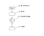
次に、全体的に積分領域を有する構成として、コンデンサを用いた完全積分回路がある。この構成を図3に示す。図3(a)は、積分部104の構成例を示している。図3(b)は、積分部104の周波数特性を示している。積分部104は、積分回路314、スイッチ回路315、タイミング回路316、グランド317、調整回路318で構成される。積分回路314は、コンデンサで構成する完全積分回路である。この回路は、図3(b)のように、直流付近より積分領域が開始される。すなわち、積分回路314は、全ての周波数成分を積分する。スイッチ回路315は、積分回路314の接続先を調整回路318かグランド317に選択する部分である。スイッチ回路315が調整回路318を選択すると、積分回路314に電荷が蓄積され積分を開始する。そして、積分結果は調整回路318に入力される。スイッチ回路315がグランド317を選択すると、積分回路314の電荷はグランド317に放電され、積分を中止する。タイミング回路316は、選択の切替え間隔を調整する。
Next, as a configuration having an integration region as a whole, there is a complete integration circuit using a capacitor. This configuration is shown in FIG. FIG. 3A shows a configuration example of the
この間隔は、処理部106の信号取り込み間隔に同期する。具体的には、処理部106が信号を取得すると積分を中止し、積分回路314の電荷が放電した後に積分を開始する。調整回路318は、増幅率を調整する部分である。積分回路314は完全積分回路であるので、図3(b)のように、直流に近い周波数成分程、増幅してしまう。図3(b)のように、増幅率が、1以上の特性を示す領域(調整領域ともいう)の信号が処理部106の測定範囲を超え、飽和することを防止するため、積分回路314の出力を調整する。このように、この積分回路104は、単位時間あたりの積分を行う部分ともいえる。図3(b)は、周波数軸を、調整領域が終わる周波数f2で正規化したものである。上述したように、THz-TDS装置の動作に対する影響を抑制するために、積分部104の時定数1/f2は微小信号検出部103の時定数τ以下にする。図3(a)に示す積分部104は、積分範囲を柔軟に設定できるという特徴を有する。
This interval is synchronized with the signal capturing interval of the processing unit 106. Specifically, when the processing unit 106 acquires a signal, the integration is stopped, and the integration is started after the charge of the integration circuit 314 is discharged. The adjustment circuit 318 is a part that adjusts the amplification factor. Since the integration circuit 314 is a complete integration circuit, as shown in FIG. 3B, the frequency component closer to the direct current is amplified. As shown in FIG. 3B, in order to prevent a signal in a region (also referred to as an adjustment region) having an amplification factor of 1 or more from exceeding the measurement range of the processing unit 106 and being saturated, the integration circuit 314 Adjust the output. Thus, the
また、別の実施形態として、図4のように、積分部104と処理部106の間にN段加算平均回路419があってもよい。N段加算平均回路419は、N個の加算回路と、加算回路の出力をNで平均化する回路で構成される。回路によって、積分部104の出力をN段に分岐し、それぞれの信号を加算した後に平均化することで、ランダムに発生する回路の熱的な雑音が1/√N倍改善されることが知られている。このような回路を挿入することで、ノイズフロアの改善が期待できる。
As another embodiment, there may be an N-stage addition averaging circuit 419 between the integrating
次に、主に図1を参照して本実施形態のテラヘルツ波測定装置の動作を説明する。尚、ここでは、発生部108と検出部109として、比較的よく利用される光伝導素子を用いることとする。 Next, the operation of the terahertz wave measuring apparatus of this embodiment will be described mainly with reference to FIG. Here, as the generation unit 108 and the detection unit 109, photoconductive elements that are relatively frequently used are used.
レーザ源107は超短パルスレーザを出力し、超短パルスレーザは、ビームスプリッタ111によってL1とL2に分岐される。超短パルスレーザL1は、遅延光学部110を介して発生部108に入射される。また、超短パルスレーザL2は検出部109に入射される。
The laser source 107 outputs an ultrashort pulse laser, and the ultrashort pulse laser is branched into L1 and L2 by a beam splitter 111. The ultrashort
処理部106は、最初の測定点(例えば、図9の1番目の測定点)を測定するため、遅延光学部110によって、超短パルスレーザL1とL2の遅延時間を調整する。超短パルスレーザL1が発生部108に到達すると、発生部108はテラヘルツ波T1を発生する。尚、このテラヘルツ波T1は、変調部105によって強度変調されている。ここでは、仮に変調周波数fsとして10KHzで変調しているものとして説明する。 The processing unit 106 adjusts the delay time of the ultrashort pulse lasers L1 and L2 by the delay optical unit 110 in order to measure the first measurement point (for example, the first measurement point in FIG. 9). When the ultrashort pulse laser L1 reaches the generation unit 108, the generation unit 108 generates a terahertz wave T1. The terahertz wave T1 is intensity-modulated by the modulation unit 105. Here, it is assumed that modulation is performed at 10 KHz as the modulation frequency fs.
テラヘルツ波T1はサンプル112上に集光され、サンプル112からテラヘルツ波T2が伝搬する。図1では、テラヘルツ波がサンプル112を透過する形態を示しているが、反射する形態でもよい。また、テラヘルツ波T1は、サンプル112に集光している形態を示しているが、平行光を入射してもよい。 The terahertz wave T1 is collected on the sample 112, and the terahertz wave T2 propagates from the sample 112. Although FIG. 1 shows a form in which the terahertz wave passes through the sample 112, a form in which the terahertz wave is reflected may be used. Moreover, although the terahertz wave T1 has shown the form condensed on the sample 112, you may inject a parallel light.
サンプル112から伝搬するテラヘルツ波T2は、サンプル112の物性により、散乱、吸収されるため、サンプル112の物性情報を含んだ信号となっている。この後、テラヘルツ波T2は検出部109に到達する。検出部109は、検出部109に入射するテラヘルツ波T2について、超短パルスレーザL2が到達した時の瞬間的な電界強度に相当する信号を出力する。検出部109として光伝導素子を用いる場合、検出部109は電流信号を出力する。 Since the terahertz wave T2 propagating from the sample 112 is scattered and absorbed by the physical properties of the sample 112, the signal includes physical property information of the sample 112. Thereafter, the terahertz wave T <b> 2 reaches the detection unit 109. The detection unit 109 outputs a signal corresponding to the instantaneous electric field strength when the ultrashort pulse laser L2 reaches the terahertz wave T2 incident on the detection unit 109. When a photoconductive element is used as the detection unit 109, the detection unit 109 outputs a current signal.
検出部109から出力された電流信号は、電流検出部102によって電圧信号に変換され、測定可能な範囲まで増幅される。ここで、遅延光学部110によって調整される遅延時間が同じである限り、超短パルスレーザL2によってサンプリングされるテラヘルツ波T2の瞬間的な電界強度の位置は同じである。そのため、電流検出部102から出力される信号は、ほぼ直流に近い信号である。しかし、本実施形態では、テラヘルツ波T1は、変調部105によって強度が変調されている。そのため、図5(a)のように、この直流信号に対して強度変調した信号が電流検出部102より出力される。図6(a)は、この電流検出部102の信号の周波数情報を示している。図示するように、電流検出部102から出力される信号は、変調周波数fsに強い信号成分を有している。
The current signal output from the detection unit 109 is converted into a voltage signal by the
電流検出部102の信号は、図5(a)で示すように、周波数fs以外の信号成分を含んでいるためSN比が低下している。そのため、電流検出部102の信号は、微小信号検出部103によって変調周波数fsの成分を抽出する。
As shown in FIG. 5A, the signal of the
図6(b)は、微小信号検出部103の周波数特性を示している。微小信号検出部103としてロックインアンプを適用する時、微小信号検出部103は、電流検出部102と変調部105の信号を乗算する乗算部と、この乗算部の出力をフィルタリングし不要な信号を減衰させるフィルタ部で構成する。図6(b)に、この乗算部の出力を示しているが、図示するように、この出力には変調周波数fsの2倍の周波数成分と直流成分、そしてノイズの成分が存在している。乗算部の出力は、変調周波数fsに近い周波数成分程直流側に現れ、変調周波数fsから離れた成分(主にノイズ成分)は高周波側に現れる。
FIG. 6B shows the frequency characteristics of the minute signal detection unit 103. When a lock-in amplifier is applied as the minute signal detection unit 103, the minute signal detection unit 103 multiplies the signals of the
微小信号検出部103のフィルタリング部は、この乗算部の出力から直流成分付近の信号を抽出する。このフィルタリング部は、時定数τを有するローパスフィルタで構成する。尚、時定数τは、ローパスフィルタのカットオフ周波数に対応する。この時定数τが、微小信号検出部103の周波数特性を制限する。図6(b)には、この微小信号検出部103の周波数特性を示している。図6(b)のように、乗算部の出力は、この周波数特性に従って高周波側の信号が減衰する。この様子を同じ図の斜線部に示している。 The filtering unit of the minute signal detection unit 103 extracts a signal near the DC component from the output of the multiplication unit. This filtering unit is composed of a low-pass filter having a time constant τ. The time constant τ corresponds to the cut-off frequency of the low-pass filter. This time constant τ limits the frequency characteristics of the minute signal detector 103. FIG. 6B shows the frequency characteristics of the minute signal detector 103. As shown in FIG. 6B, the output of the multiplication unit attenuates the signal on the high frequency side according to this frequency characteristic. This is shown in the shaded area in the same figure.
図5(b)には、この微小信号検出部103の時間波形の出力を示している。図5(b)をみると、直流成分が抽出されている。この直流成分がテラヘルツ波の瞬間的な電界に相当している。例えば、遅延光学部110の調整量を変化させると、この直流成分の値が変動する。この変動の速度をどの程度追従させるかは、図6(b)で示した微小信号検出部103の周波数特性に依る。例えば、追従の速度を速くしたい場合、微小信号検出部103の時定数τを小さくする(周波数領域に換算すると、カットオフ周波数を大きくする)。追従の速度を速くすると、テラヘルツ波の時間波形を速く取得できる。ところが、時定数τを小さくしていくと、図6(b)のように、和の周波数成分2fs以降の周波数成分を十分減衰できなくなるので、図5(b)で示した時間波形のSN比は低下する。 FIG. 5B shows the time waveform output of the minute signal detector 103. As shown in FIG. 5B, a DC component is extracted. This DC component corresponds to the instantaneous electric field of the terahertz wave. For example, when the adjustment amount of the delay optical unit 110 is changed, the value of the DC component changes. The extent to which the speed of this fluctuation is followed depends on the frequency characteristics of the minute signal detector 103 shown in FIG. For example, when it is desired to increase the follow-up speed, the time constant τ of the minute signal detection unit 103 is decreased (when converted to the frequency domain, the cutoff frequency is increased). If the tracking speed is increased, the time waveform of the terahertz wave can be acquired quickly. However, if the time constant τ is decreased, the frequency components after the sum frequency component 2fs cannot be sufficiently attenuated as shown in FIG. 6B. Therefore, the SN ratio of the time waveform shown in FIG. Will decline.
本発明では、テラヘルツ波の高速取得に伴うSN比の低下を、積分部ないし積算部104で補償することが特徴である。図1のように、微小信号検出部103の出力は、積分部104に入力される。図6(c)は、積分部104の周波数特性を示している。ここでは、積分部104としてローパスフィルタを適用した例を示している。この積分部104の周波数特性は、測定システムの動作への影響を小さくするために、積分部104の時定数は、微小信号検出部103の時定数τよりも小さくする。そして、上述したように、積分部104では、微小信号検出部103で減衰しきれなかった和の周波数成分2fs以降の周波数成分を減衰させる必要があるため、積分部104の時定数は1/(2fs)より大きくする。ここでは、積分部104の時定数は、微小信号検出部103の時定数τと同じ値を選択して説明する。
The present invention is characterized in that the integration unit or the
図6(c)のように、微小信号検出部102の出力は、積算部104の周波数特性に従って、周波数成分2fs以降の周波数成分が減衰する。この結果を、斜線部で示している。この結果、図5(c)のように、積分部104の出力は、微小信号検出部102の出力に比べ、SN比が改善され、より直流に近い形となる。
As shown in FIG. 6C, the output of the
処理部106は、この積分部104の出力を記録する。処理部106は、再び遅延光学部110によって超短パルスレーザL1とL2の遅延時間を調整し、次の測定点を測定する。この一連の動作を繰り返すことで、処理部106は、サンプル112を透過したテラヘルツ波の時間波形を構築する。このテラヘルツ波の時間波形をフーリエ変換することで、周波数スペクトルを得ることもできる。そして、サンプル112がない時の周波数スペクトルと比較することで、透過率を算出することができる。また、更なるSN比の改善のため、テラヘルツ波の時間波形を複数回取得し、これらの加算平均を取得する場合もある(ラピッドスキャン方式ともいう)。
The processing unit 106 records the output of the
このように、本実施形態では、テラヘルツ波の波形取得に要する時間を短くすることに伴うSN比の悪化(ノイズフロアの上昇)を補償し、テラヘルツ波の高速取得とノイズフロアの改善を両立することが可能となる。 As described above, in the present embodiment, the deterioration of the SN ratio (rising of the noise floor) accompanying the shortening of the time required for acquiring the waveform of the terahertz wave is compensated, and both the high-speed acquisition of the terahertz wave and the improvement of the noise floor are achieved. It becomes possible.
更に具体的な実施例を説明する。
(実施例1)
実施例1では、測定例を示す。尚、これまでの説明と共通する部分の説明は省略する。本実施例では、発生部108と検出部109として、低温成長させたガリウムヒ素(LT-GaAs)膜にアンテナを形成した光伝導素子を用いる。アンテナは中心に間隙5μmを有するダイポールアンテナ(アンテナ長30μm)を用いる。レーザ源107は、パルス幅50フェムト秒、中心波長800nm、繰り返し周波数76MHzのチタンサファイアレーザを用いる。遅延光学部110は、折り返し光学系を用い、3μm単位で超短パルスレーザL1の光路長を調整する。超短パルスレーザL1とL2の強度は5mWである。
Further specific examples will be described.
Example 1
Example 1 shows a measurement example. In addition, the description of the part which is common in the above description is abbreviate | omitted. In this embodiment, as the generation unit 108 and the detection unit 109, photoconductive elements in which an antenna is formed on a gallium arsenide (LT-GaAs) film grown at a low temperature are used. As the antenna, a dipole antenna (antenna length of 30 μm) having a gap of 5 μm at the center is used. As the laser source 107, a titanium sapphire laser having a pulse width of 50 femtoseconds, a center wavelength of 800 nm, and a repetition frequency of 76 MHz is used. The delay optical unit 110 uses a folding optical system and adjusts the optical path length of the ultrashort pulse laser L1 in units of 3 μm. The intensity of the ultrashort pulse lasers L1 and L2 is 5 mW.
本実施例では、サンプル112は用いず、自由空間である。変調部105は、発生部108に20Vpp、1KHzの矩形波を出力する。また、変調部105は、同じ周波数のTTL信号を微小信号検出部103に出力する。尚、測定部101の雰囲気は窒素で置換している。測定中の温度は24度、湿度は3%以下である。
In this embodiment, the sample 112 is not used and is a free space. The modulation unit 105 outputs a 20 Vpp, 1 KHz rectangular wave to the generation unit 108. Further, the modulation unit 105 outputs a TTL signal having the same frequency to the minute signal detection unit 103. Note that the atmosphere of the
電流検出部102は、電流電圧変換回路であり107V/Aの変換効率を有する。微小信号検出部103はロックインアンプであり、感度は100mV、時定数は30m秒である。積分部104はローパスフィルタを用い、時定数は3m秒である。
The
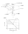
ここでは、処理部106は、測定点4000点で時間波形を構築しており、測定回数は1回であるとする。この時のテラヘルツ波の周波数スペクトルを図7に示す。図7は、積算部104がない従来の測定系の測定結果と、本実施例の測定結果を示している。図7のように積分部104を用いることでノイズフロアの位置が低下し、周波数スペクトル幅が広がっている様子が分かる。ノイズフロアの低下の割合は、波形の加算平均処理による手法の効果に換算すると、時間波形を10回測定し加算平均した量に相当する。この結果、測定帯域が0.5THz程広がっている。
Here, it is assumed that the processing unit 106 constructs a time waveform at 4000 measurement points and the number of measurements is one. The frequency spectrum of the terahertz wave at this time is shown in FIG. FIG. 7 shows the measurement result of the conventional measurement system without the integrating
このように、積分部104を用いることでノイズフロアの改善が実現できる。そのため、従来の測定方法に比べ、同程度のSN比を得るために必要な時間波形の測定回数を減らすことができ、測定時間の高速化を容易にする。
Thus, the noise floor can be improved by using the
(実施例2)
実施例2では、別の測定例を示す。尚、これまでの説明と共通する部分の説明は省略する。本実施例では、積分部104としてローパスフィルタを用い、時定数は10m秒である。
(Example 2)
Example 2 shows another measurement example. In addition, the description of the part which is common in the above description is abbreviate | omitted. In this embodiment, a low-pass filter is used as the
図8は、この積分部104を用いた時のテラヘルツ波の周波数スペクトルである。図8は、積算部104がない従来の測定系の測定結果と、本実施例の測定結果を示している。本実施例においても、積分部104を用いることでノイズフロアの位置が低下し、周波数スペクトル幅が広がっている様子が分かる。ノイズフロアの低下の割合は、波形の加算平均処理による手法の効果に換算すると、時間波形を10回測定し加算平均した量に相当する。この結果、測定帯域が0.5THz程広がっている。
FIG. 8 shows a frequency spectrum of a terahertz wave when the
このように、本実施例でも、積分部104を用いることでノイズフロアの改善が実現できる。そのため、従来の測定方法に比べ、同程度のSN比を得るために必要な時間波形の測定回数を減らすことができ、測定時間の高速化を容易にする。
Thus, also in the present embodiment, the noise floor can be improved by using the
101 測定部
102 電流検出部
103 微小信号検出部
104 積分部(積算部)
105 変調部
106 処理部
108 発生部
109 検出部
110 遅延光学部
419 N段加算平均回路
T1、T2 テラヘルツ波
101
105 Modulating unit 106 Processing unit 108 Generating unit 109 Detection unit 110 Delay optical unit 419 N-stage addition averaging circuit
T1, T2 Terahertz wave
Claims (6)
周波数fsの信号成分を含むテラヘルツ波パルスを検出する検出部と、
時定数τを有し、前記検出部からの信号から周波数fsの信号成分を検出する微小信号検出部と、
前記微小信号検出部の出力段に接続される積分部と、
取り込み間隔Δtで前記積分部からデータを取り込みテラヘルツ波パルスの時間波形を構築する処理部と、を有し、
時定数τは取り込み間隔Δt以下で、
前記積分部の時定数は、時定数τ以下で、かつ1/(2fs)より大きい特性である、
ことを特徴とする測定装置。 A measurement device that acquires a time waveform of a terahertz wave pulse by time domain spectroscopy,
A detection unit for detecting a terahertz wave pulse including a signal component of frequency fs;
A minute signal detector having a time constant τ and detecting a signal component of frequency fs from the signal from the detector;
An integrator connected to the output stage of the minute signal detector;
A processing unit that captures data from the integration unit at a capturing interval Δt and constructs a time waveform of the terahertz wave pulse , and
The time constant τ is less than the capture interval Δt,
The time constant of the integration unit is a characteristic that is less than the time constant τ and greater than 1 / (2fs).
A measuring device.
周波数fsの信号成分を含むテラヘルツ波パルスを検出する検出ステップと、
時定数τを有し、前記検出ステップで検出される信号から周波数fsの信号成分を検出する微小信号検出ステップと、
前記微小信号検出ステップで検出される信号を積算する積分ステップと、
取り込み間隔Δtで、前記積分ステップにおいて生成されたデータを取り込みテラヘルツ波パルスの時間波形を構築する処理ステップと、を有し、
時定数τは取り込み間隔Δt以下で、
前記積分ステップの時定数は、時定数τ以下で、かつ1/(2fs)より大きい特性である、
ことを特徴とする測定方法。 A measurement method for obtaining a time waveform of a terahertz wave pulse by time domain spectroscopy,
A detection step of detecting a terahertz wave pulse including a signal component of frequency fs;
A minute signal detection step having a time constant τ and detecting a signal component of frequency fs from the signal detected in the detection step;
An integration step for integrating the signals detected in the minute signal detection step;
Processing steps for capturing the data generated in the integration step at a capturing interval Δt and constructing a time waveform of a terahertz wave pulse ,
The time constant τ is less than the capture interval Δt,
The time constant of the integration step is a characteristic that is less than the time constant τ and greater than 1 / (2fs).
A measuring method characterized by the above.
Priority Applications (2)
| Application Number | Priority Date | Filing Date | Title |
|---|---|---|---|
| JP2009012454A JP5438327B2 (en) | 2009-01-23 | 2009-01-23 | Measuring device using terahertz waves |
| US12/642,427 US7906764B2 (en) | 2009-01-23 | 2009-12-18 | Measuring apparatus using terahertz wave |
Applications Claiming Priority (1)
| Application Number | Priority Date | Filing Date | Title |
|---|---|---|---|
| JP2009012454A JP5438327B2 (en) | 2009-01-23 | 2009-01-23 | Measuring device using terahertz waves |
Publications (3)
| Publication Number | Publication Date |
|---|---|
| JP2010169541A JP2010169541A (en) | 2010-08-05 |
| JP2010169541A5 JP2010169541A5 (en) | 2012-03-01 |
| JP5438327B2 true JP5438327B2 (en) | 2014-03-12 |
Family
ID=42353406
Family Applications (1)
| Application Number | Title | Priority Date | Filing Date |
|---|---|---|---|
| JP2009012454A Expired - Fee Related JP5438327B2 (en) | 2009-01-23 | 2009-01-23 | Measuring device using terahertz waves |
Country Status (2)
| Country | Link |
|---|---|
| US (1) | US7906764B2 (en) |
| JP (1) | JP5438327B2 (en) |
Families Citing this family (3)
| Publication number | Priority date | Publication date | Assignee | Title |
|---|---|---|---|---|
| JP5669629B2 (en) * | 2010-05-18 | 2015-02-12 | キヤノン株式会社 | Terahertz wave measuring apparatus and measuring method |
| CN104330160B (en) * | 2014-10-16 | 2017-01-18 | 中国电子科技集团公司第五十研究所 | Terahertz spectrum analyzer |
| CN106248616B (en) * | 2016-09-27 | 2017-10-24 | 深圳市太赫兹科技创新研究院有限公司 | The full polarization state detection spectrometer of Terahertz |
Family Cites Families (7)
| Publication number | Priority date | Publication date | Assignee | Title |
|---|---|---|---|---|
| US5952818A (en) * | 1996-05-31 | 1999-09-14 | Rensselaer Polytechnic Institute | Electro-optical sensing apparatus and method for characterizing free-space electromagnetic radiation |
| JP2002538423A (en) * | 1999-02-23 | 2002-11-12 | テラプロウブ リミテッド | Method and apparatus for terahertz imaging |
| FR2876465B1 (en) * | 2004-10-08 | 2007-01-19 | Commissariat Energie Atomique | TERAHERTZ OPTICAL DOOR |
| JP2006145372A (en) * | 2004-11-19 | 2006-06-08 | Matsushita Electric Ind Co Ltd | Terahertz electromagnetic wave generator |
| JP2006266908A (en) * | 2005-03-24 | 2006-10-05 | Tochigi Nikon Corp | Instrument and method for measuring terahertz pulse light |
| US7291856B2 (en) * | 2005-04-28 | 2007-11-06 | Honeywell International Inc. | Sensor and methods for measuring select components in moving sheet products |
| JP4654996B2 (en) * | 2006-07-12 | 2011-03-23 | 株式会社島津製作所 | Terahertz wave response measuring device |
-
2009
- 2009-01-23 JP JP2009012454A patent/JP5438327B2/en not_active Expired - Fee Related
- 2009-12-18 US US12/642,427 patent/US7906764B2/en not_active Expired - Fee Related
Also Published As
| Publication number | Publication date |
|---|---|
| US20100187420A1 (en) | 2010-07-29 |
| US7906764B2 (en) | 2011-03-15 |
| JP2010169541A (en) | 2010-08-05 |
Similar Documents
| Publication | Publication Date | Title |
|---|---|---|
| US7551269B2 (en) | Apparatus and method for obtaining information related to terahertz waves | |
| JP5894745B2 (en) | Integrated circuit inspection equipment | |
| US8841596B2 (en) | Quasi continuous photon detection system | |
| US8207501B2 (en) | Apparatus and method for measuring terahertz wave | |
| JP6386655B2 (en) | Terahertz wave generator and spectroscopic device using the same | |
| JP2009075069A (en) | Apparatus and method for obtaining information related to terahertz wave | |
| US8513940B2 (en) | Method of measuring terahertz wave and apparatus therefor | |
| US20140306101A1 (en) | Device and method for measuring the distribution of physical quantities in an optical fiber | |
| JP2010190887A (en) | Analyzing apparatus | |
| CN108489959B (en) | Coherent anti-Stokes Raman spectrum scanning device and method | |
| JP5438327B2 (en) | Measuring device using terahertz waves | |
| CA3076846A1 (en) | Linear time-gate method and system for ultrashort pulse characterization | |
| JP3918054B2 (en) | Method and apparatus for measuring the photoresponse of a substance | |
| JP4819466B2 (en) | Transfer characteristic measuring device, method, program, and recording medium | |
| JP5836479B2 (en) | Time domain spectroscopic device and time domain spectroscopic analysis system | |
| US5172191A (en) | Sweeping photoreflectance spectroscopy | |
| JP2012145383A (en) | Terahertz wave apparatus and operation method thereof | |
| JP6194380B2 (en) | Integrated circuit inspection equipment | |
| RU2789628C1 (en) | Pulsed terahertz spectrometer with a semiconductor oscillator based on the effect of surface field modulation | |
| US20170082668A1 (en) | Measuring apparatus, measuring method, and recording medium | |
| Fuchs et al. | High resolution FROG system for the characterization of ps laser pulses | |
| Nagashima et al. | Improved signal extraction method for single-pulse heterodyne cars spectroscopy | |
| Vogel et al. | Performance of photoconductive receivers at 1030 nm excited by high average power THz pulses | |
| JP2006098216A (en) | Time series conversion pulse spectroscopic measuring instrument capable of detecting time series feeble signal, and method therefor | |
| Davis | Designing a Custom Frequency-Resolved Optical Gating (FROG) Spectrometer |
Legal Events
| Date | Code | Title | Description |
|---|---|---|---|
| A521 | Request for written amendment filed |
Free format text: JAPANESE INTERMEDIATE CODE: A523 Effective date: 20120112 |
|
| A621 | Written request for application examination |
Free format text: JAPANESE INTERMEDIATE CODE: A621 Effective date: 20120112 |
|
| A977 | Report on retrieval |
Free format text: JAPANESE INTERMEDIATE CODE: A971007 Effective date: 20130129 |
|
| A131 | Notification of reasons for refusal |
Free format text: JAPANESE INTERMEDIATE CODE: A131 Effective date: 20130328 |
|
| A521 | Request for written amendment filed |
Free format text: JAPANESE INTERMEDIATE CODE: A523 Effective date: 20130507 |
|
| TRDD | Decision of grant or rejection written | ||
| A01 | Written decision to grant a patent or to grant a registration (utility model) |
Free format text: JAPANESE INTERMEDIATE CODE: A01 Effective date: 20131114 |
|
| A61 | First payment of annual fees (during grant procedure) |
Free format text: JAPANESE INTERMEDIATE CODE: A61 Effective date: 20131213 |
|
| LAPS | Cancellation because of no payment of annual fees |