JP5437101B2 - Portable electronic devices - Google Patents
Portable electronic devices Download PDFInfo
- Publication number
- JP5437101B2 JP5437101B2 JP2010033887A JP2010033887A JP5437101B2 JP 5437101 B2 JP5437101 B2 JP 5437101B2 JP 2010033887 A JP2010033887 A JP 2010033887A JP 2010033887 A JP2010033887 A JP 2010033887A JP 5437101 B2 JP5437101 B2 JP 5437101B2
- Authority
- JP
- Japan
- Prior art keywords
- unit
- antenna
- conductive
- key
- reference potential
- Prior art date
- Legal status (The legal status is an assumption and is not a legal conclusion. Google has not performed a legal analysis and makes no representation as to the accuracy of the status listed.)
- Expired - Fee Related
Links
Images

Classifications
-
- H—ELECTRICITY
- H04—ELECTRIC COMMUNICATION TECHNIQUE
- H04B—TRANSMISSION
- H04B1/00—Details of transmission systems, not covered by a single one of groups H04B3/00 - H04B13/00; Details of transmission systems not characterised by the medium used for transmission
- H04B1/38—Transceivers, i.e. devices in which transmitter and receiver form a structural unit and in which at least one part is used for functions of transmitting and receiving
-
- H—ELECTRICITY
- H01—ELECTRIC ELEMENTS
- H01Q—ANTENNAS, i.e. RADIO AERIALS
- H01Q1/00—Details of, or arrangements associated with, antennas
- H01Q1/12—Supports; Mounting means
- H01Q1/22—Supports; Mounting means by structural association with other equipment or articles
- H01Q1/24—Supports; Mounting means by structural association with other equipment or articles with receiving set
- H01Q1/241—Supports; Mounting means by structural association with other equipment or articles with receiving set used in mobile communications, e.g. GSM
- H01Q1/242—Supports; Mounting means by structural association with other equipment or articles with receiving set used in mobile communications, e.g. GSM specially adapted for hand-held use
- H01Q1/243—Supports; Mounting means by structural association with other equipment or articles with receiving set used in mobile communications, e.g. GSM specially adapted for hand-held use with built-in antennas
-
- H—ELECTRICITY
- H01—ELECTRIC ELEMENTS
- H01Q—ANTENNAS, i.e. RADIO AERIALS
- H01Q1/00—Details of, or arrangements associated with, antennas
- H01Q1/48—Earthing means; Earth screens; Counterpoises
-
- H—ELECTRICITY
- H01—ELECTRIC ELEMENTS
- H01Q—ANTENNAS, i.e. RADIO AERIALS
- H01Q3/00—Arrangements for changing or varying the orientation or the shape of the directional pattern of the waves radiated from an antenna or antenna system
- H01Q3/24—Arrangements for changing or varying the orientation or the shape of the directional pattern of the waves radiated from an antenna or antenna system varying the orientation by switching energy from one active radiating element to another, e.g. for beam switching
- H01Q3/247—Arrangements for changing or varying the orientation or the shape of the directional pattern of the waves radiated from an antenna or antenna system varying the orientation by switching energy from one active radiating element to another, e.g. for beam switching by switching different parts of a primary active element
-
- H—ELECTRICITY
- H04—ELECTRIC COMMUNICATION TECHNIQUE
- H04M—TELEPHONIC COMMUNICATION
- H04M1/00—Substation equipment, e.g. for use by subscribers
- H04M1/02—Constructional features of telephone sets
Landscapes
- Engineering & Computer Science (AREA)
- Computer Networks & Wireless Communication (AREA)
- Signal Processing (AREA)
- Telephone Set Structure (AREA)
- Support Of Aerials (AREA)
- Transceivers (AREA)
Description
本発明は、アンテナ部を備える携帯電子機器に関する。 The present invention relates to a portable electronic device including an antenna unit.
携帯電子機器には、第1の筐体と第2の筐体とから構成され、使用態様に応じてヒンジ部を介して開状態と閉状態とに移行可能に構成される折り畳み型のものがある。このような折り畳み型の携帯電子機器は、アンテナ部を介して外部と通信を行う通信機能を有している。 A portable electronic device includes a foldable type device that includes a first housing and a second housing, and is configured to be able to shift between an open state and a closed state via a hinge according to a usage mode. is there. Such a foldable portable electronic device has a communication function for communicating with the outside via an antenna unit.
例えば、特許文献1によれば、第1の筐体と第2の筐体の開閉状態に応じて、アンテナ整合回路のグランドの位置を切り替える技術が開示されている。
特許文献1は、適応的にグランドの位置を切り替えることによって、アンテナ電流分布を良好にし、アンテナ特性を劣化させないようにしている。
For example,
また、携帯電子機器において、アンテナ部の近傍にリフレクタを配置することによって、アンテナ特性の向上を図ることが可能な技術が提案されている。 In portable electronic devices, a technique that can improve antenna characteristics by arranging a reflector in the vicinity of an antenna unit has been proposed.
ところで、携帯電子機器においては、アンテナ部の指向方向が決まっているため、例えば、この指向方向側に導電物等が配置されてしまうとアンテナ部の特性が劣化する場合がある。 By the way, in the portable electronic device, since the directivity direction of the antenna unit is determined, for example, if a conductive material or the like is disposed on the directivity direction side, the characteristics of the antenna unit may be deteriorated.
本発明は、アンテナ部の指向方向が決まっていることに起因するアンテナ部の特性の劣化を低減することが可能な携帯電子機器を提供することを目的とする。 An object of the present invention is to provide a portable electronic device capable of reducing deterioration in characteristics of an antenna unit due to the determined orientation direction of the antenna unit.
本発明に係る携帯電子機器は、上記課題を解決するために、操作部と、アンテナ部と、前記アンテナ部の近傍に配置される回路基板と、前記回路基板に設けられ、前記操作部に対する操作を検出する導電性の操作検出部と、前記操作検出部に対向して前記回路基板に設けられる基準電位部と、前記アンテナ部に対向して前記回路基板に設けられる導電部と、前記基準電位部と前記導電部とが電気的に接続されるか否かを切り替えることが可能な切替部と、を有し、前記導電部は、前記操作部に対する操作が行われると前記切替部によって前記基準電位部と電気的に接続され、前記操作部に対する操作が行われていない場合には前記切替部によって前記基準電位部と電気的に接続されない。 In order to solve the above problems, a portable electronic device according to the present invention is provided with an operation unit, an antenna unit, a circuit board disposed in the vicinity of the antenna unit, and the operation with respect to the operation unit. A conductive operation detection unit for detecting the reference voltage, a reference potential unit provided on the circuit board facing the operation detection unit, a conductive unit provided on the circuit board facing the antenna unit, and the reference potential It possesses a and the conductive portion and are electrically connected to whether or not it is possible to switch the switching unit part, wherein the conductive portion, the reference and operation to the operation unit is performed by the switching unit When it is electrically connected to the potential unit and the operation unit is not operated, it is not electrically connected to the reference potential unit by the switching unit.
また、携帯電子機器においては、前記切替部は、前記操作部に対する押圧操作に連動して、前記基準電位部及び前記導電部の少なくとも一方に当接しない第1位置から前記基準電位部及び前記導電部に当接する第2位置へ移動する移動部材を有することが好ましい。 Further, in the portable electronic device, the switching unit is connected to the reference potential unit and the conductive unit from a first position that does not contact at least one of the reference potential unit and the conductive unit in conjunction with a pressing operation on the operation unit. It is preferable to have a moving member that moves to a second position that contacts the part.
また、携帯電子機器においては、所定の条件が満たされた場合に、前記切替部により前記基準電位部と前記導電部とが電気的に接続されるか否かを切り替える制御部をさらに備えることが好ましい。 The portable electronic device may further include a control unit that switches whether the reference potential unit and the conductive unit are electrically connected by the switching unit when a predetermined condition is satisfied. preferable.
また、携帯電子機器においては、前記導電部は、前記回路基板の前記操作検出部と対向する位置に設けられ、前記基準電位部と前記導電部との間に、前記アンテナ部の共振周波数帯域の信号を遮断する遮断部が設けられることが好ましい。 In the portable electronic device, the conductive portion is provided at a position facing the operation detection portion of the circuit board, and a resonance frequency band of the antenna portion is provided between the reference potential portion and the conductive portion. It is preferable that a blocking part for blocking the signal is provided.
また、携帯電子機器においては、前記アンテナ部は、前記導電部と対向する第1対向面を有し、前記導電部は、前記アンテナ部と対向する第2対向面を有し、前記第1対向面の形状と前記第2対向面の形状とが略同一であることが好ましい。 In the portable electronic device, the antenna unit has a first facing surface facing the conductive portion, the conductive portion has a second facing surface facing the antenna portion, and the first facing It is preferable that the shape of the surface and the shape of the second facing surface are substantially the same.
また、携帯電子機器においては、前記導電部は、前記アンテナ部の共振周波数に対応する波長の4分の1の長さの間隔をおいて前記アンテナ部と対向して配置されることが好ましい。 In the portable electronic device, it is preferable that the conductive portion is disposed to face the antenna portion with an interval having a length of a quarter of a wavelength corresponding to the resonance frequency of the antenna portion.
また、携帯電子機器においては、前記導電部は、互いに電気的に接続されていない第1部及び第2部を有し、前記切替部は、前記基準電位部と前記第1部又は前記第2部とが電気的に接続されるか否かを切り替え可能に構成されることが好ましい。 In the portable electronic device, the conductive portion includes a first portion and a second portion that are not electrically connected to each other, and the switching portion includes the reference potential portion and the first portion or the second portion. It is preferable to be able to switch whether or not the unit is electrically connected.
本発明によれば、アンテナ部の指向方向が決まっていることに起因するアンテナ部の特性の劣化を低減することが可能である。 ADVANTAGE OF THE INVENTION According to this invention, it is possible to reduce the deterioration of the characteristic of the antenna part resulting from the directional direction of the antenna part being decided.
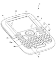
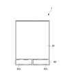
以下、本発明を実施するための好ましい実施形態について、図面を参照しながら説明する。まず、本発明の携帯電子機器の一実施形態に係る携帯電話機1の基本構造について、図1を参照しながら説明する。図1は、携帯電子機器の一実施形態に係る携帯電話機1の外観斜視図である。
Hereinafter, preferred embodiments for carrying out the present invention will be described with reference to the drawings. First, a basic structure of a
図1に示すように、携帯電話機1は、筐体2を備えると共に、この筐体2の前面10に配置される操作部11と、表示部21と、スピーカ22と、マイク23とを備える。
操作部11は、使用者により操作がなされる捜査対象である。表示部21は、文字情報や画像情報等の各種情報を表示するための装置である。スピーカ22は、通話の相手側の音声を出力するための装置である。マイク23は、携帯電話機1の使用者が通話時に発した音声を入力するための装置である。
As shown in FIG. 1, the
The
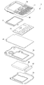
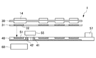
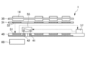
次に、図2及び図3を参照して、携帯電話機1の内部構成について説明する。図2は、携帯電話機1の分解斜視図である。図3は、図1に示す携帯電話機1をA−Aで切断したときの切断面を模式的に示す断面図である。
Next, the internal configuration of the
携帯電話機1は、フロントケース2aと、リアケース2bと、バッテリリッド2cとを備える。フロントケース2aとリアケース2bとは、互いの凹状の内側面が向き合うように配置され、互いの外周縁が重なり合うようにして結合される。また、リアケース2bの外面には、バッテリリッド2cがリアケース2bに対して着脱可能に結合される。また、携帯電話機1は、フロントケース2aとリアケース2bとの間に、表示部21と、キーシート30を含む操作部11と、メタルドームシート31と、回路基板40と、アンテナ部60と、バッテリ80とが配置される。表示部21と、操作部11と、メタルドームシート31と、回路基板40と、アンテナ部60と、バッテリ80とは、筐体2の厚さ方向(筐体2の内部側の方向又は筐体2の外部側の方向)において互いに支持し合うと共に、フロントケース2a及びリアケース2bにより挟持されて、筐体2の内部に設けられる。
The
表示部21は、例えば、液晶ディスプレイや有機EL(エレクトロルミネッセンス)ディスプレイ等から構成される。
操作部11は、キートップ13、14、15とキーシート30とから構成される操作対象である。キートップ13、14、15は、直方体形状に形成された樹脂であり、キートップ13、14、15は、フロントケース2aに形成されている貫通穴13a、14a、15a(開口部)を介して外部に露出する。キートップ13、14、15は、使用者により筐体2の内部側に押圧されると、その押圧力により筐体2の内部側に押し込まれる。なお、以下、使用者によるキートップ13、14、15に対する筐体2の内部側への押圧を、「操作」と略して説明する。
The
The
キーシート30は、可撓性を有するゴムから形成されるシート状の部材である。キーシート30における筐体2の外部側の面には、キートップ13、14、15が設けられている。また、キーシート30における筐体2の内部側の面には、キートップ13、14、15に対応して、筐体2の内部側に突出した押し子が形成されている。
The
したがって、使用者により操作がなされると、キートップ13、14、15と共に、キーシート30の押し子も筐体2の内部側に押し込まれることとなる。
一方、操作が終了して、キートップ13、14、15に対する筐体2の内部側への押圧力が低減すると、キーシート30は、可撓性を有するゴムの反発力によりキートップ13、14、15は筐体2の外部側に押し戻され、キートップ13、14、15と共に、操作前の状態に戻る。
Therefore, when the user performs an operation, the pusher of the
On the other hand, when the operation is finished and the pressing force on the inner side of the housing 2 against the key tops 13, 14, 15 is reduced, the
メタルドームシート31は、可撓性のあるフィルム状の部材である。メタルドームシート31には、キートップ13、14、15の数と同数のメタルドーム32が、筐体2の外部側の面に設けられている。メタルドームシート31は、使用者の操作によって筐体2の内部側に押し込まれるキートップ13、14、15に押圧されて筐体2の内部側に押し込まれる。また、操作が終了して、キートップ13、14、15に対する筐体2の内部側への押圧力が低減すると、メタルドームシート31は、可撓性を有するゴムの反発力により、キートップ13、14、15が筐体2の外部側に押し戻され、キートップ13、14、15及びキーシート30と共に、操作前の状態に戻る。
The
メタルドーム32は、導電性を有する中空の凸状金属片であり、凸面が筐体2の外部側を向いて構成される。また、メタルドーム32は、キーシート30の押し子に対向するようにメタルドームシート31に設けられている。そして、キーシート30の押し子が、使用者の操作によって、筐体2のキートップ13、14、15と共に筐体2の内部側に押し込まれると、押し子によって凸面が中空領域までつぶされて弾性変形する。
The
一方、使用者の操作が終了すると、キートップ13、14、15に対する筐体2の内部側への押圧力が低減され、上述のとおり、キーシート30の押し子は、筐体2の外部側に押し戻されるため、メタルドーム32の凸面は、つぶれが解除され、弾性力により変形前の状態に戻る。
On the other hand, when the user's operation is completed, the pressing force on the inner side of the housing 2 against the key tops 13, 14, 15 is reduced, and the pusher of the
使用者は、この操作に伴うメタルドーム32の弾性変形を通じてクリック感を得ることができる。すなわち、使用者は、キートップ13、14、15を押下したことを好適に実感することができる。
The user can obtain a click feeling through the elastic deformation of the
回路基板40は、種々の電子部品に接続され、それら電子部品を用いて各種の制御を司る制御部57をはじめ、多数の電子部品が実装されたリジッド基板である。回路基板40に実装された電子部品は、導電性の回路パターンを通じて互いに電気的に接続されている。実装された電子部品は、回路パターンを通じて、互いに信号の授受を行っている。
The
また、回路基板40には、メタルドーム32の凸面の内面に対向する位置に、スイッチ端子51(操作検出部)が設けられている。スイッチ端子51は、回路基板40上に設けられた回路パターンの一部を構成する導電性のパターンであり、中空の円形形状で形成された導電性の外周部分と、第1部分の中空領域において円形形状に形成された導電性の内周部分とを備える。外周部分と内周部分とは、互いに接しないよう回路基板40に設けられる。したがって、外周部分と内周部分とは、互いに非導通の関係にある。
The
ただし、外周部分と内周部分とは、回路基板40において、使用者による操作に伴って弾性変形したメタルドーム32の凸面の内面に当接する位置に設けられる。したがって、外周部分と内周部分とは、使用者によって操作された場合には、変形したメタルドーム32によって互いに導通されることとなる。つまり、外周部分と内周部分とは、使用者により操作がされていない状態においては非導通の状態となり、使用者により操作がされると導通状態となる。すなわち、スイッチ端子51は、使用者による操作の有無に応じて電気的な状態が変化する。
However, the outer peripheral portion and the inner peripheral portion are provided on the
スイッチ端子51は、回路基板40に形成された導電性の回路パターンによって制御部57に接続される。制御部57は、スイッチ端子51の電気的な状態変化を信号として受信し、その受信信号に基づいて使用者による操作の有無及びその内容を判別する。
The
このようにして、メタルドーム32、スイッチ端子51、及びスイッチ端子51と制御部57とを接続する回路パターンは、操作を検出する導電性の操作検出部として機能することになる。
Thus, the
また、回路基板40には、回路パターンの一部を構成する基準電位部41(グランドパターン)が形成される。基準電位部41は、メタルドーム32、スイッチ端子51、及びスイッチ端子51と制御部57とを接続する回路パターンと、アンテナ部60とのアイソレーションを図るためのグランドである。基準電位部41は、アイソレーション効果を高める目的で、回路基板40において、メタルドーム32、スイッチ端子51、及びスイッチ端子51と制御部57とを接続する回路パターンに対向して設けられる。また、基準電位部41の一部は、回路基板40に形成されたスルーホールを介して回路基板40における筐体2の外部側の表面に露出している。
In addition, a reference potential portion 41 (ground pattern) that forms a part of the circuit pattern is formed on the
アンテナ部60は、高周波信号に共振するアンテナエレメントである。本実施形態においては、アンテナ部60は、電話機能やメール機能を実行するための800MHz帯の高周波信号に共振するよう構成される。アンテナ部60は、給電ポイント及び回路基板40の回路パターンを介して制御部57に接続されている。制御部57は、アンテナ部60に共振される800MHz帯の信号に対して復調又は変調処理を行い、電話機能やメール機能を実行する。
バッテリ80は、回路基板40に実装された電子部品等に対して電力を供給する電源であり、例えば、リチウムイオン電池等で構成させる。
The
The
このように携帯電話機1は、操作部11を介して使用者が操作したり、表示部21を介して各種情報を視認したり、アンテナ部60を利用して電話機能やメール機能を利用することができ、携帯電話としての機能を発揮する。
また、携帯電話機1は、上述の構成に加え、アンテナ部60の指向性を制御するための新規な構成を備えている。
As described above, the
In addition to the above configuration, the
以下、アンテナ部60の指向性を制御するための構成について説明する。
携帯電話機1は、図3及び図4に示すように、回路基板40において、導電部42及び切替部55をさらに有している。
Hereinafter, a configuration for controlling the directivity of the
As shown in FIGS. 3 and 4, the
導電部42は、回路基板40の回路パターンの一部からなり、アンテナ部60に対向する位置に設けられる。また、導電部42は、スルーホールを介して回路基板40における筐体2の外部側の表面に形成された基準電位部41に隣接して回路基板40の同表面上に形成されている。
The
切替部55は、回路基板40とメタルドームシート31との間に配置された導電性の薄い板状部材である。切替部55の一端部は、スルーホールを介して回路基板40における筐体2の外部側の表面に形成された基準電位部41上にはんだ等の公知の固定手段で固定されている(図4(a))。切替部55の他端部は、回路基板40とメタルドームシート31との間において、所定の距離だけ離間して導電部42に対向する位置に配置される。
The switching
また、切替部55は、筐体2の厚さ方向に対して、一端部を支点とした弾性力が働くように、一端部から他端部にかけて複数回折り曲げられた形状を備えている。
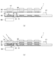
そして、切替部55は、メタルドームシート31が、使用者の操作に伴って筐体2の内部側に押し込まれると、他端部がメタルドームシート31によって筐体2の内部側に押圧されて、導電部42に当接する位置まで筐体2の内部側に押し込まれる(図4(b))。
一方、操作が終了して、メタルドームシート31が操作前の状態に戻ると、切替部55の一端部を支点として、折り曲げられた形状に起因する弾性力によって他端部は、操作前の位置に戻る。
In addition, the switching
Then, when the
On the other hand, when the operation is completed and the
したがって、切替部55は、使用者による操作の有無に応じて、基準電位部41には当接するが導電部42に当接しない第1位置から、基準電位部41及び導電部42の双方に当接する第2位置へ移動可能に構成される。すなわち、切替部55は、基準電位部41と導電部42との電気的な接続状態を切り替え可能に構成される。
Therefore, the switching
以上の構成により、導電部42は、使用者の操作が行われると切替部55により基準電位部41と電気的に接続されて同電位(グランド)となり、操作が行われていない状態においては基準電位部41との電気的な接続がなくなって、基準電位部41から浮いた状態となる。
With the above configuration, when the user's operation is performed, the
また、基準電位部41と導電部42との電気的な接続状態の変化に伴い、アンテナ部60に対向する領域のグランド面積も、変化することとなる。すなわち、使用者の操作が行われている状態においては、導電部42はグランドとなるため、その結果、アンテナ部60に対向する領域のグランド面積は、基準電位部41の面積と導電部42の面積の和により得られる面積となる。これに対し、使用者の操作が行われていない状態においては、導電部42は基準電位部41から浮いた状態となるため、アンテナ部60に対向する領域のグランド面積は、基準電位部41の面積と同等の面積となる。
In addition, as the electrical connection state between the reference
したがって、操作の有無に応じて、アンテナ部60に対向する領域のグランド面積が変化し、アンテナ部60に共振する電磁波のグランドによる放射(送信)及び吸収(受信)の方向も併せて変化することとなる。本実施形態の場合は、操作がされている状態においては、導電部42がグランドになると共に、アンテナ部60に対してフロントケース2a側に対向することとなる。したがって、アンテナ部60からの電磁波は、導電部42によって、リアケース2b側に放射される。
Therefore, depending on the presence or absence of operation, the ground area of the region facing the
一方、操作がされていない状態においては、導電部42は、基準電位部41から浮いた状態となるため、アンテナ部60に対するフロントケース2a側への放射を阻むグランドがなくなる。したがって、アンテナ部60からの電磁波は、操作がされている状態に比してフロントケース2a側に放射されることとなる。
On the other hand, when the operation is not performed, the
このようにして、携帯電話機1は、使用者の操作によって、アンテナ部60の特性を調整することができる。このため、携帯電話機1は、例えば、アンテナ部60の指向方向側に導電物等が配置されてアンテナ部60の特性の劣化が生じる恐れがある場合においても、アンテナ部60の指向性を容易に調整することができ、アンテナ特性の劣化を低減することができる。
In this way, the
また、従来のように、筐体の方向を種々の方向に向けることなく、操作部11への操作さえ行えば、携帯電話機1は、携帯電話機1の指向性を制御することができ、アンテナ部60の特性を好適に維持することができる。また、携帯電話機1は、操作部11にアンテナ部60の指向性調整用の操作部を設ければ、使用者の操作によって、必要に応じてアンテナ部60の指向性を、さらに容易な操作で調整することができる。つまり、アンテナ部60の特性は好適に維持される。
Further, as in the prior art, the
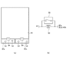
ここで、携帯電話機1は、図5に示すように、所定の条件が満たされた場合に、電気的な切替スイッチである切替部55により基準電位部41と導電部42とが電気的に接続されるか否かを制御部57によって切り替える構成であっても良い。
Here, as shown in FIG. 5, in the
また、所定の条件とは、キートップ13、14、15に対する操作が検出された場合や、携帯電話機1が机等の被載置面に載置されたことが検出された場合をいう。なお、本実施例では、メタルドーム32及びスイッチ端子51により、キートップ13、14、15に対する物理的な押圧操作を検出しているが、これに限られず、操作部11がタッチパネル式で構成される場合には、タッチ操作を検出しても良い。
The predetermined condition refers to a case where an operation on the key tops 13, 14, 15 is detected or a case where it is detected that the
制御部57は、携帯電話機1が被載置面に載置されたことを検出した場合や、メタルドーム32及びスイッチ端子51によってキートップ13、14、15に対する操作を検出した場合には、基準電位部41と導電部42が電気的に接続されるように切替部55を制御する。ここで、携帯電話機1が被載置面に載置されたか否かの検出方法としては、例えば、リアケース2bの所定の場所に光量を検出する光検出部を配置し、当該光検出部により検出した値が所定値を下回った場合に、制御部57は、携帯電話機1が被載置面に載置されたと判断しても良い。
When the
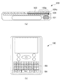
ここで、携帯端末においては、パソコンのようなキー配列(qwertyキー配列)により構成される操作部を有するタイプ(スマートフォン)が開発されている。
このようなqwertyキー配列により構成される操作部は、テンキーにより構成される操作部に比して、キーの数が大幅に増え、かつ操作性も担保する必要があるため、ある程度広い面積が必要になる。
Here, in the portable terminal, a type (smart phone) having an operation unit configured by a key arrangement (qwerty key arrangement) like a personal computer has been developed.
The operation unit configured with such a qwerty key arrangement requires a large area to some extent because the number of keys must be significantly increased and operability must be ensured as compared to an operation unit configured with a numeric keypad. become.
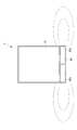
一方、従来の携帯端末100では、十分なアンテナ特性を得るために、アンテナ部101が配置される領域には、グランド部102を配置させないように構成していた。
しかし、操作部103がqwertyキー配列により構成される携帯端末においては、小型化及び薄型化の要請から、例えば、筐体の厚さ方向において、操作部103の一部とアンテナ部101とが重畳してしまう場合がある(図6(a)、(b)を参照。)。
On the other hand, in the conventional
However, in a portable terminal in which the
また、操作部103の下部には回路基板104が配置されているので、結果として、回路基板104の一部104aとアンテナ部101が筐体の厚さ方向で重畳することになる(図6(a)、(b)を参照。)。
Further, since the
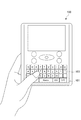
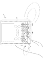
また、このように筐体の厚さ方向において、操作部103の一部103aとアンテナ部101とが重畳する場合には、使用者は、操作部103のキー(qwertyキー)を操作する際に、アンテナ部101の少なくとも一部を手で遮蔽してしまう(図7を参照。)。このような場合には、アンテナ部101が送受信する電磁波が使用者の手によって吸収され、アンテナ部101の特性が劣化してしまう。
In addition, when a
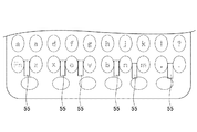
そこで、本実施例の携帯電話機1においては、図8及び図9に示すように、導電部42は、回路基板40に設けられるメタルドーム32及び不図示の信号線と対向する位置に設けられる。また、導電部42は、互いに電気的に接続されていない第1部42a及び第2部42bを有し、切替部55は、基準電位部41と第1部42a又は第2部42bとが電気的に接続されるか否かを切り替え可能に構成される。
Therefore, in the
具体的には、図9に示すように、導電部42は、アンテナ部60と筐体の厚さ方向に重畳する位置に設けられ、筐体の短手方向において左側に位置する第1部42aと右側に位置する第2部42bを有する。このときのアンテナ部60による電波の放射(送信)及び吸収(受信)方向は、図10に模式的に示すように、筐体の短手方向に広がる。
Specifically, as shown in FIG. 9, the
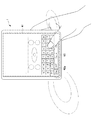
ここで、第1部42aの上部に配置されているキー(例えば、「Cap」キーや、「Fn」キーや、「z」キー等)が押圧された場合には、切替部55により第1部42aと基準電位部41とが電気的に導通する。このような場合には、第2部42b以外は全てグランド部になり、反射板(リフレクタ)としての機能を発揮するので、アンテナ部60による電波の放射(送信)及び吸収(受信)方向は、図11に模式的に示すように、第1部42aが配置されている側に比較して第2部42bが配置されている側に大きく広がる。
Here, when a key (for example, a “Cap” key, an “Fn” key, a “z” key, or the like) arranged on the upper portion of the
一方、第2部42bの上部に配置されているキー(例えば、「Ent」キーや、「Ctrl」キーや、「m」キー等)が押圧された場合には、切替部55により第2部42bと基準電位部41とが電気的に導通する。このような場合には、第1部42a以外は全てグランド部になり、反射板(リフレクタ)としての機能を発揮するので、アンテナ部60による電波の放射(送信)及び吸収(受信)方向は、図12に模式的に示すように、第2部42bが配置されている側に比較して第1部42aが配置されている側に大きく広がる。
On the other hand, when a key (for example, “Ent” key, “Ctrl” key, “m” key, etc.) arranged on the upper part of the
このようにして、携帯電話機1は、押圧されたキーの位置に応じて、アンテナ部60の放射パターンを変更することができる。
ここで、使用者がキーを押圧しているということは、携帯電話機1を手で強く押さえ付けているということになるので、携帯電話機1は、アンテナ部60による電波の放射(送信)及び吸収(受信)方向をキーが押圧されていない側に集中するように制御することによって、人体の影響を低減し、良好なアンテナ特性を得ることができる。
In this way, the
Here, the fact that the user is pressing the key means that the
基準電位部41と導電部42を電気的に導通させる方法は、上述したように、切替部55により行われる。ここで、切替部55は、図13に示すように、回路基板40上において、複数個所に配置されていても良い。図13では、「Fn」キーと「z」キーの間、「x」キーと「c」キーの間、「c」キーと「v」キーの間、「b」キーと「n」キーの間、「n」キーと「m」キーの間、「、」キーと「.」キーの間の6箇所に切替部55が配置されている様子を模式的に示している。
The method of electrically connecting the reference
また、携帯電話機1は、図14に示すように、操作部11を中央で分離させ、左側に寄せられた左側キー群11aと右側に寄せられた右側キー群11bに分離する構成であっても良い。このように構成することによって、例えば、使用者が「v」キーを押した場合に、「b」キーと「n」キーの間にある切替部55を押圧してしまうことを抑制できる。また、左側キー群11aの下部に導電部42の第1部42aが配置され、右側キー群11bの下部に導電部42の第2部42bが配置されるので、携帯電話機1は、押圧されたキーの位置に応じて、精度良く第1部42a又は第2部42bと基準電位部41を電気的に導通することができる。
Further, as shown in FIG. 14, the
なお、図14では、「Space」キーは、左側キー群11aと右側キー群11bの両方に跨って示しているが、これに限れず、いずれか一方に寄せても良いし、中心で分離させ、一方を左側に寄せ、他方を右側に寄せる構成であっても良い。
In FIG. 14, the “Space” key is shown to straddle both the left
ここで、導電部42が基準電位部41と電気的に接続されていない場合には、回路基板40に設けられるメタルドーム32及び信号線(不図示)が、アンテナ部60が送受信する電磁波と不要な共振を起こす場合がある。そこで、携帯電話機1は、図8に示すように、基準電位部41と導電部42との間に設けられ、アンテナ部60の共振周波数帯域の信号を遮断する遮断部59を有する。遮断部59は、例えばコイルやLC共振回路で構成され、アンテナ部60の共振周波数帯域(例えば、800MHz帯)の信号を遮断することができる。
Here, when the
また、第1部42aと第2部42bは、初期状態(例えば、使用者によってキー操作がされていない状態や、机等の被載置面に載置されていない状態等)においては、回路基板40の基準電位部41とは電気的に導通しない状態である。基準電位部41と導電部42との間に高周波遮断手段である遮断部59が設けられるので、基準電位部41と導電部42とは、直流的にはショートした状態かつ高周波的にはオープン状態となる。
In addition, the
また、携帯電話機1は、このような構成において、使用者により操作部11の所定のキーが押圧された場合には、切替部55が基準電位部41と導電部42を電気的に導通させるので、高周波的にもショートした状態になる。
Further, in the
以上のような構成により、切替部55により基準電位部41と導電部42とが電気的に接続されていない場合であっても、回路基板40に設けられるメタルドーム32及び信号線(不図示)が、アンテナ部60が送受信する電磁波と不要な共振を起こすことを抑制できる。
With the above configuration, even when the reference
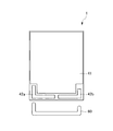
また、携帯電話機1においては、アンテナ部60の導電部42に対向している第1対向面Aの形状と、導電部42のアンテナ部60に対向している第2対向面Bの形状とが略同一形状であることが好ましい。
In the
ここで、図15には、詳細は後述するように、二つの独立した導電部42(第1部42a及び第2部42b)の形状が、それぞれ対応するアンテナ部60の形状と略同一となる様子を模式的に示している。
Here, in FIG. 15, as will be described in detail later, the shapes of the two independent conductive portions 42 (the
このようにして、携帯電話機1は、第1対向面Aと第2対向面Bの形状を略同一形状にすることによって、導波路を構成することになる。よって、アンテナ部60の指向性を好適に制御して電磁波の送受信を行うことができ、アンテナ特性を向上させることができる。
In this way, the
また、携帯電話機1においては、導電部42は、アンテナ部60の共振周波数に対応する波長の4分の1の長さの間隔をおいてアンテナ部60と対向して配置されることが好ましい。
Further, in the
このように構成されることにより、アンテナ部60の指向性をさらに好適に制御して電磁波の送受信を行うことができ、アンテナ特性を向上させることができる。
By being configured in this manner, the directivity of the
<他の実施例>
また、他の実施例としては、以下のものがある。
使用者は、一般的に、利き腕で携帯電話機1の操作を行う。また、使用者が右手で携帯電話機1を把持した場合には、携帯電話機1の右側が覆われ、使用者が左手で携帯電話機1を把持した場合には、携帯電話機1の左側が覆われる。
<Other embodiments>
Other examples include the following.
A user generally operates the
そこで、携帯電話機1は、予め、使用者の利き腕を設定しておき、利き腕の設定が左利きの場合には、導電部42の左側(第1部42a)を基準電位部41と電気的に接続し、また、利き腕の設定が右利きの場合には、導電部42の右側(第2部42b)を基準電位部41と電気的に接続しておく。そして、携帯電話機1は、キーが操作された場合には、操作されたキーの位置に応じて第1部42a又は第2部42bと基準電位部41を電気的に導通する。
Therefore, the
このように構成することによって、携帯電話機1は、使用者の使用状態に応じてアンテナ部60による電波の放射(送信)及び吸収(受信)方向を変更することができ、良好なアンテナ特性を得ることができる。なお、携帯電話機1は、被載置面に載置されたことを検出した場合には、第1部42a及び第2部42bが浮島状態になるように切り替える構成であっても良い。
With this configuration, the
また、携帯電話機1は、利き腕の設定に応じて、第1部42a又は第2部42bと基準電位部41を電気的に導通させ、その後、メモ帳アプリケーション等のqwertyキーが使用されるアプリケーションが起動された場合には、被載置面に載置されたことを検出しても、この状態を維持する構成であっても良い。
In addition, the
なお、上述では、導電部42は、第1部42aと第2部42bの二つに分離する例を示したが、これに限られず、3つ以上に分離して構成されていても良い。このような構成によれば、携帯電話機1は、アンテナ部60による電波の放射(送信)及び吸収(受信)方向を多様に制御することができる。
In the above description, the example in which the
なお、携帯電話機1は、図1に示す形態に限定されることはない。例えば、携帯電話機1は、表示部を有する表示部側筐体と、操作部を有する操作部側筐体と、表示部側筐体と操作部側筐体とを結合するヒンジ部とを備える折り畳み式の携帯電話機であっても良い。また、携帯電話機は、操作部側筐体と表示部側筐体とを重ね合わせた状態から一方の筐体を一方向にスライドさせるようにしたスライド式や、重ね合せ方向に沿う軸線を中心に一方の筐体を回転させるようにした回転式や、操作部側筐体と表示部側筐体とを2軸ヒンジを介して連結したものであっても良い。
The
また、切替部55は、操作の有無に応じて、基準電位部41と導電部42の少なくとも一方に当接していない位置から基準電位部41及び導電部42の双方に当接する位置へ移動可能なものであれば良いため、必ずしも上述の構成に限定されない。例えば、切替部55は、基準電位部41及び導電部42の双方に当接しないように、一端部から他端部にかけてメタルドームシート31における筐体2の内部側の面に固定されていても良い。そして、使用者の操作によりメタルドームシート31が筐体2の内部側に押し込まれた際に、いずれかの領域において、基準電位部41及び導電部42の双方に当接し、基準電位部41と導電部42との電気的な接続状態を切り替える構成であっても良い。
In addition, the switching
また、上記の実施形態において、切替部55がメカニカルスイッチにより構成されている場合には切替部55が移動部材そのものである構成となっているが、本発明はこれに限定されず、切替部55が移動部材と他の部材とを含んで構成されていても良い。
Moreover, in said embodiment, when the switching
1 携帯電話機
11 操作部
13、14、15 キートップ
30 キーシート
32 メタルドーム
40 回路基板
41 基準電位部
42 導電部
42a 第1部
42b 第2部
51 スイッチ端子
55 切替部(移動部材)
57 制御部
59 遮断部
60 アンテナ部
DESCRIPTION OF
57
Claims (1)
アンテナ部と、
前記アンテナ部の近傍に配置される回路基板と、
前記回路基板に設けられ、前記操作部に対する操作を検出する導電性の操作検出部と、
前記操作検出部に対向して前記回路基板に設けられる基準電位部と、
前記アンテナ部に対向して前記回路基板に設けられる導電部と、
前記基準電位部と前記導電部とが電気的に接続されるか否かを切り替えることが可能な切替部と、を有し、
前記導電部は、前記操作部に対する操作が行われると前記切替部によって前記基準電位部と電気的に接続され、前記操作部に対する操作が行われていない場合には前記切替部によって前記基準電位部と電気的に接続されない
携帯電子機器。 An operation unit;
An antenna section;
A circuit board disposed in the vicinity of the antenna unit;
A conductive operation detection unit that is provided on the circuit board and detects an operation on the operation unit;
A reference potential unit provided on the circuit board facing the operation detection unit;
A conductive portion provided on the circuit board facing the antenna portion;
Have a, a switching unit capable of the reference potential portion and the conductive portion switches whether or not electrically connected,
The conductive unit is electrically connected to the reference potential unit by the switching unit when an operation is performed on the operation unit, and the reference potential unit is configured by the switching unit when an operation is not performed on the operation unit. Portable electronic devices that are not electrically connected to
Priority Applications (3)
| Application Number | Priority Date | Filing Date | Title |
|---|---|---|---|
| JP2010033887A JP5437101B2 (en) | 2010-02-18 | 2010-02-18 | Portable electronic devices |
| KR1020110013700A KR101193356B1 (en) | 2010-02-18 | 2011-02-16 | Portable electronic apparatus |
| US13/030,530 US8698698B2 (en) | 2010-02-18 | 2011-02-18 | Portable electronic device |
Applications Claiming Priority (1)
| Application Number | Priority Date | Filing Date | Title |
|---|---|---|---|
| JP2010033887A JP5437101B2 (en) | 2010-02-18 | 2010-02-18 | Portable electronic devices |
Publications (3)
| Publication Number | Publication Date |
|---|---|
| JP2011172012A JP2011172012A (en) | 2011-09-01 |
| JP2011172012A5 JP2011172012A5 (en) | 2013-02-28 |
| JP5437101B2 true JP5437101B2 (en) | 2014-03-12 |
Family
ID=44369299
Family Applications (1)
| Application Number | Title | Priority Date | Filing Date |
|---|---|---|---|
| JP2010033887A Expired - Fee Related JP5437101B2 (en) | 2010-02-18 | 2010-02-18 | Portable electronic devices |
Country Status (3)
| Country | Link |
|---|---|
| US (1) | US8698698B2 (en) |
| JP (1) | JP5437101B2 (en) |
| KR (1) | KR101193356B1 (en) |
Families Citing this family (2)
| Publication number | Priority date | Publication date | Assignee | Title |
|---|---|---|---|---|
| US10686252B2 (en) * | 2014-06-16 | 2020-06-16 | Apple Inc. | Electronic device with patch antenna |
| US10784572B2 (en) | 2017-06-02 | 2020-09-22 | Apple Inc. | Electronic device with speaker and antenna isolation |
Family Cites Families (11)
| Publication number | Priority date | Publication date | Assignee | Title |
|---|---|---|---|---|
| JP2000330946A (en) * | 1999-05-17 | 2000-11-30 | Casio Comput Co Ltd | Function switching device and its program recording medium |
| JP3551122B2 (en) * | 2000-04-07 | 2004-08-04 | 日本電気株式会社 | Mobile phone equipment |
| JP4118064B2 (en) * | 2002-02-26 | 2008-07-16 | 株式会社東芝 | Antenna device |
| JP3847301B2 (en) * | 2004-02-27 | 2006-11-22 | 株式会社国際電気通信基礎技術研究所 | TV receiver with antenna |
| JP4511387B2 (en) * | 2005-02-25 | 2010-07-28 | 京セラ株式会社 | Wireless communication terminal |
| JP2006287432A (en) * | 2005-03-31 | 2006-10-19 | Tohoku Univ | Mobile communication terminal |
| JP4896493B2 (en) * | 2005-10-28 | 2012-03-14 | 京セラ株式会社 | Wireless communication terminal |
| JP4287427B2 (en) * | 2005-12-20 | 2009-07-01 | 株式会社東芝 | Antenna device for portable terminal and portable terminal |
| JP4712775B2 (en) | 2007-08-06 | 2011-06-29 | シャープ株式会社 | Wireless terminal device |
| CN101828378B (en) * | 2007-10-18 | 2014-03-19 | 日本电气株式会社 | Portable communication apparatus |
| JP5073517B2 (en) * | 2008-01-29 | 2012-11-14 | パナソニック株式会社 | MIMO antenna apparatus and wireless communication apparatus including the same |
-
2010
- 2010-02-18 JP JP2010033887A patent/JP5437101B2/en not_active Expired - Fee Related
-
2011
- 2011-02-16 KR KR1020110013700A patent/KR101193356B1/en not_active Expired - Fee Related
- 2011-02-18 US US13/030,530 patent/US8698698B2/en not_active Expired - Fee Related
Also Published As
| Publication number | Publication date |
|---|---|
| US20110199283A1 (en) | 2011-08-18 |
| JP2011172012A (en) | 2011-09-01 |
| KR101193356B1 (en) | 2012-10-19 |
| US8698698B2 (en) | 2014-04-15 |
| KR20110095184A (en) | 2011-08-24 |
Similar Documents
| Publication | Publication Date | Title |
|---|---|---|
| CN102224632B (en) | Communication device | |
| US11088470B2 (en) | Antenna device and mobile terminal having the same | |
| US6545642B1 (en) | Antenna/push-button assembly and portable radiotelephone including the same | |
| US6914570B2 (en) | Antenna system for a communication device | |
| EP2448065B1 (en) | Mobile communiction terminal with a frame and antenna | |
| US20170005393A1 (en) | Antenna module and mobile device using same | |
| JP4828482B2 (en) | Portable wireless device | |
| US8494601B2 (en) | Communication device | |
| KR20030019636A (en) | Mobile wireless terminal | |
| US20180115054A1 (en) | Mobile device | |
| WO2005041350A1 (en) | Mobile radio apparatus | |
| US8593350B2 (en) | Wireless communication terminal | |
| JP5437101B2 (en) | Portable electronic devices | |
| US8712465B2 (en) | Mobile terminal device capable of more effectively utilizing operation portions, conductive portion, operation detecting unit, power supply unit, and signal processing unit | |
| JP2012134770A (en) | Radio communication apparatus | |
| FI124886B (en) | PIFA antenna with extendable part | |
| JP2009111698A (en) | Mobile terminal and power supply cable wiring method for mobile terminal | |
| KR20110097903A (en) | Handheld terminal | |
| JP5778393B2 (en) | Portable electronic devices | |
| KR101604715B1 (en) | Portable terminal | |
| KR20130053934A (en) | Mobile terminal | |
| JP5306774B2 (en) | Mobile device | |
| JP4818973B2 (en) | Mobile terminal device | |
| KR100810317B1 (en) | Apparatus and method for controlling antenna interference signal of portable terminal supporting reinforcement device | |
| JP5503984B2 (en) | Mobile device |
Legal Events
| Date | Code | Title | Description |
|---|---|---|---|
| RD04 | Notification of resignation of power of attorney |
Free format text: JAPANESE INTERMEDIATE CODE: A7424 Effective date: 20120803 |
|
| A521 | Written amendment |
Free format text: JAPANESE INTERMEDIATE CODE: A523 Effective date: 20130109 |
|
| A621 | Written request for application examination |
Free format text: JAPANESE INTERMEDIATE CODE: A621 Effective date: 20130115 |
|
| A977 | Report on retrieval |
Free format text: JAPANESE INTERMEDIATE CODE: A971007 Effective date: 20130725 |
|
| A131 | Notification of reasons for refusal |
Free format text: JAPANESE INTERMEDIATE CODE: A131 Effective date: 20130813 |
|
| A521 | Written amendment |
Free format text: JAPANESE INTERMEDIATE CODE: A523 Effective date: 20131010 |
|
| TRDD | Decision of grant or rejection written | ||
| A01 | Written decision to grant a patent or to grant a registration (utility model) |
Free format text: JAPANESE INTERMEDIATE CODE: A01 Effective date: 20131112 |
|
| A61 | First payment of annual fees (during grant procedure) |
Free format text: JAPANESE INTERMEDIATE CODE: A61 Effective date: 20131211 |
|
| R150 | Certificate of patent or registration of utility model |
Ref document number: 5437101 Country of ref document: JP Free format text: JAPANESE INTERMEDIATE CODE: R150 Free format text: JAPANESE INTERMEDIATE CODE: R150 |
|
| LAPS | Cancellation because of no payment of annual fees |