JP5436306B2 - Retractable tool assembly and method for refurbishing a reactor vessel core shroud weld - Google Patents
Retractable tool assembly and method for refurbishing a reactor vessel core shroud weld Download PDFInfo
- Publication number
- JP5436306B2 JP5436306B2 JP2010080359A JP2010080359A JP5436306B2 JP 5436306 B2 JP5436306 B2 JP 5436306B2 JP 2010080359 A JP2010080359 A JP 2010080359A JP 2010080359 A JP2010080359 A JP 2010080359A JP 5436306 B2 JP5436306 B2 JP 5436306B2
- Authority
- JP
- Japan
- Prior art keywords
- rail
- baffle plate
- weld
- tool
- assembly
- Prior art date
- Legal status (The legal status is an assumption and is not a legal conclusion. Google has not performed a legal analysis and makes no representation as to the accuracy of the status listed.)
- Active
Links
- 238000000034 method Methods 0.000 title description 5
- 238000007689 inspection Methods 0.000 claims description 21
- 230000008439 repair process Effects 0.000 claims description 16
- 230000003750 conditioning effect Effects 0.000 claims description 5
- 230000000712 assembly Effects 0.000 description 18
- 238000000429 assembly Methods 0.000 description 18
- 230000007246 mechanism Effects 0.000 description 8
- 239000002826 coolant Substances 0.000 description 7
- XLYOFNOQVPJJNP-UHFFFAOYSA-N water Substances O XLYOFNOQVPJJNP-UHFFFAOYSA-N 0.000 description 6
- 238000005336 cracking Methods 0.000 description 5
- 238000009499 grossing Methods 0.000 description 5
- 238000009835 boiling Methods 0.000 description 3
- 238000001816 cooling Methods 0.000 description 3
- 239000012530 fluid Substances 0.000 description 3
- 230000001680 brushing effect Effects 0.000 description 2
- 238000005260 corrosion Methods 0.000 description 2
- 230000007797 corrosion Effects 0.000 description 2
- 239000002184 metal Substances 0.000 description 2
- 239000007769 metal material Substances 0.000 description 2
- 230000002093 peripheral effect Effects 0.000 description 2
- 238000003466 welding Methods 0.000 description 2
- 230000009471 action Effects 0.000 description 1
- 230000006835 compression Effects 0.000 description 1
- 238000007906 compression Methods 0.000 description 1
- 230000007613 environmental effect Effects 0.000 description 1
- 239000007788 liquid Substances 0.000 description 1
- 230000004048 modification Effects 0.000 description 1
- 238000012986 modification Methods 0.000 description 1
- 238000007517 polishing process Methods 0.000 description 1
- 238000003825 pressing Methods 0.000 description 1
- 230000008569 process Effects 0.000 description 1
- 238000007670 refining Methods 0.000 description 1
Images


Classifications
-
- B—PERFORMING OPERATIONS; TRANSPORTING
- B23—MACHINE TOOLS; METAL-WORKING NOT OTHERWISE PROVIDED FOR
- B23P—METAL-WORKING NOT OTHERWISE PROVIDED FOR; COMBINED OPERATIONS; UNIVERSAL MACHINE TOOLS
- B23P23/00—Machines or arrangements of machines for performing specified combinations of different metal-working operations not covered by a single other subclass
- B23P23/04—Machines or arrangements of machines for performing specified combinations of different metal-working operations not covered by a single other subclass for both machining and other metal-working operations
-
- B—PERFORMING OPERATIONS; TRANSPORTING
- B23—MACHINE TOOLS; METAL-WORKING NOT OTHERWISE PROVIDED FOR
- B23P—METAL-WORKING NOT OTHERWISE PROVIDED FOR; COMBINED OPERATIONS; UNIVERSAL MACHINE TOOLS
- B23P6/00—Restoring or reconditioning objects
-
- G—PHYSICS
- G21—NUCLEAR PHYSICS; NUCLEAR ENGINEERING
- G21C—NUCLEAR REACTORS
- G21C19/00—Arrangements for treating, for handling, or for facilitating the handling of, fuel or other materials which are used within the reactor, e.g. within its pressure vessel
- G21C19/20—Arrangements for introducing objects into the pressure vessel; Arrangements for handling objects within the pressure vessel; Arrangements for removing objects from the pressure vessel
- G21C19/207—Assembling, maintenance or repair of reactor components
-
- Y—GENERAL TAGGING OF NEW TECHNOLOGICAL DEVELOPMENTS; GENERAL TAGGING OF CROSS-SECTIONAL TECHNOLOGIES SPANNING OVER SEVERAL SECTIONS OF THE IPC; TECHNICAL SUBJECTS COVERED BY FORMER USPC CROSS-REFERENCE ART COLLECTIONS [XRACs] AND DIGESTS
- Y02—TECHNOLOGIES OR APPLICATIONS FOR MITIGATION OR ADAPTATION AGAINST CLIMATE CHANGE
- Y02E—REDUCTION OF GREENHOUSE GAS [GHG] EMISSIONS, RELATED TO ENERGY GENERATION, TRANSMISSION OR DISTRIBUTION
- Y02E30/00—Energy generation of nuclear origin
- Y02E30/30—Nuclear fission reactors
-
- Y—GENERAL TAGGING OF NEW TECHNOLOGICAL DEVELOPMENTS; GENERAL TAGGING OF CROSS-SECTIONAL TECHNOLOGIES SPANNING OVER SEVERAL SECTIONS OF THE IPC; TECHNICAL SUBJECTS COVERED BY FORMER USPC CROSS-REFERENCE ART COLLECTIONS [XRACs] AND DIGESTS
- Y10—TECHNICAL SUBJECTS COVERED BY FORMER USPC
- Y10T—TECHNICAL SUBJECTS COVERED BY FORMER US CLASSIFICATION
- Y10T29/00—Metal working
- Y10T29/49—Method of mechanical manufacture
- Y10T29/49718—Repairing
-
- Y—GENERAL TAGGING OF NEW TECHNOLOGICAL DEVELOPMENTS; GENERAL TAGGING OF CROSS-SECTIONAL TECHNOLOGIES SPANNING OVER SEVERAL SECTIONS OF THE IPC; TECHNICAL SUBJECTS COVERED BY FORMER USPC CROSS-REFERENCE ART COLLECTIONS [XRACs] AND DIGESTS
- Y10—TECHNICAL SUBJECTS COVERED BY FORMER USPC
- Y10T—TECHNICAL SUBJECTS COVERED BY FORMER US CLASSIFICATION
- Y10T29/00—Metal working
- Y10T29/51—Plural diverse manufacturing apparatus including means for metal shaping or assembling
-
- Y—GENERAL TAGGING OF NEW TECHNOLOGICAL DEVELOPMENTS; GENERAL TAGGING OF CROSS-SECTIONAL TECHNOLOGIES SPANNING OVER SEVERAL SECTIONS OF THE IPC; TECHNICAL SUBJECTS COVERED BY FORMER USPC CROSS-REFERENCE ART COLLECTIONS [XRACs] AND DIGESTS
- Y10—TECHNICAL SUBJECTS COVERED BY FORMER USPC
- Y10T—TECHNICAL SUBJECTS COVERED BY FORMER US CLASSIFICATION
- Y10T29/00—Metal working
- Y10T29/53—Means to assemble or disassemble
- Y10T29/531—Nuclear device
-
- Y—GENERAL TAGGING OF NEW TECHNOLOGICAL DEVELOPMENTS; GENERAL TAGGING OF CROSS-SECTIONAL TECHNOLOGIES SPANNING OVER SEVERAL SECTIONS OF THE IPC; TECHNICAL SUBJECTS COVERED BY FORMER USPC CROSS-REFERENCE ART COLLECTIONS [XRACs] AND DIGESTS
- Y10—TECHNICAL SUBJECTS COVERED BY FORMER USPC
- Y10T—TECHNICAL SUBJECTS COVERED BY FORMER US CLASSIFICATION
- Y10T29/00—Metal working
- Y10T29/54—Miscellaneous apparatus
Description
本明細書に開示する発明は一般に、原子炉内の溶接部を検査し、磨き直し(refurbish)、または補修するツールに関し、具体的には、沸騰水型原子炉(BWR)の炉心シュラウドの周囲の溶接部を磨き直すツールに関する。 The invention disclosed herein generally relates to a tool for inspecting, refurbishing, or repairing welds in a nuclear reactor, and more particularly, around a boiling water reactor (BWR) core shroud. The present invention relates to a tool for refining a welded portion of a metal.
BWRは一般に、圧力容器の壁を形成する概ね円筒形の室と、圧力容器内の炉心シュラウドとを含む。炉心シュラウドは原子炉炉心を含み、炉心シュラウドと炉心はともに、圧力容器に流入し、圧力容器内を流れる水/冷却材中に浸されている。 A BWR generally includes a generally cylindrical chamber that forms the wall of the pressure vessel and a core shroud within the pressure vessel. The core shroud includes a nuclear reactor core, and both the core shroud and the core flow into the pressure vessel and are immersed in water / coolant flowing through the pressure vessel.
圧力容器と炉心シュラウドの間には、シュラウドの周囲に広がる幅約18インチ(0.45m)の環状の間隙がある。この間隙は、ジェットポンプによって炉心内を循環する冷却材/減速材で満たされている。この間隙は、炉心シュラウドの外側に配置され、冷却材/減速材を炉心内へ導くジェットポンプ、配管およびその他の構成要素を組み立てるための領域を提供する。これらのジェットポンプアセンブリ、配管およびその他の構成要素は一般に間隙内の深い位置にあり、冷却および減速流体中に沈んでいる。さらに、この間隙は、炉心シュラウド上の溶接部ならびに間隙内に配置されたジェットポンプアセンブリ、配管およびその他の構成要素を検査し、補修するために使用するツールおよび機器の通路となる。 Between the pressure vessel and the core shroud is an annular gap of about 18 inches (0.45 m) wide that extends around the shroud. This gap is filled with a coolant / moderator that circulates in the core by a jet pump. This gap is located outside the core shroud and provides an area for assembling jet pumps, piping and other components that direct the coolant / moderator into the core. These jet pump assemblies, piping and other components are generally deep within the gap and are submerged in the cooling and deceleration fluid. In addition, this gap provides a passage for tools and equipment used to inspect and repair welds on the core shroud and jet pump assemblies, piping and other components located within the gap.
炉心シュラウド上の溶接部は、冷却材および水に浸され、他の環境条件にさらされるため、腐食および亀裂を生じやすい。この溶接部は定期的に検査され、磨き直され、補修される。この溶接部に到達するためには、炉心シュラウドを開き、圧力容器と炉心シュラウドの間の間隙を通して、ツールをケーブルによって下ろす。間隙の幅が狭く、冷却/減速流体が存在し、間隙内にジェットポンプアセンブリおよびその他の構成要素があるため、間隙内の深い位置にある溶接部および構成要素までツールおよび検査機器を下ろすことは特に難しい。間隙内の深い位置にある溶接部およびその他の構成要素にアクセスするためには、特定のツール、センサ、ならびにこれらのツールおよびセンサを支持するキャリッジが必要である。1つの難点は、キャリッジ上のツールまたはセンサが、炉心シュラウドまたは間隙内の他の構成要素に対して作業を実行している間、炉心シュラウドまたはジェットポンプアセンブリにキャリッジを固定することである。例えば、ツールが、溶接部を平滑にすることによって溶接部を磨き直すワイヤブラシである場合には、ワイヤブラシが溶接部を平滑にするときに、ワイヤブラシを溶接部に強く押し当てなければならず、キャリッジをシュラウドにしっかりと固定しなければならない。したがって、シュラウドと圧力容器の間の間隙内の溶接部にアクセスするツールおよび機器が長い間求められている。 The welds on the core shroud are subject to corrosion and cracking because they are immersed in coolant and water and exposed to other environmental conditions. This weld is regularly inspected, refurbished and repaired. To reach this weld, the core shroud is opened and the tool is lowered by cable through the gap between the pressure vessel and the core shroud. Because the gap width is narrow, there is cooling / deceleration fluid, and there are jet pump assemblies and other components in the gap, it is not possible to lower the tools and inspection equipment to welds and components deep in the gap Especially difficult. In order to access welds and other components deep within the gap, certain tools, sensors, and carriages that support these tools and sensors are required. One difficulty is that a tool or sensor on the carriage secures the carriage to the core shroud or jet pump assembly while performing work on the core shroud or other components in the gap. For example, if the tool is a wire brush that polishes the weld by smoothing the weld, the wire brush must be pressed firmly against the weld when the wire brush smoothes the weld. First, the carriage must be securely fixed to the shroud. Accordingly, tools and equipment that access the weld in the gap between the shroud and the pressure vessel have long been sought.
一実施形態では、本発明は、原子炉圧力容器内に含まれる、原子炉炉心の炉心シュラウドを取り巻いて周囲方向に延びる溶接部にアクセスするように適合されたアセンブリであって、炉心シュラウドと原子炉圧力容器との間の間隙内のバッフルプレートに接するように適合された下面を有するバッフルプレートレールと、バッフルプレートレールの上部領域にスライド可能に結合されたテレスコープ式レールと、テレスコープ式レールの上部領域にスライド可能に結合され、溶接部コンディショニングツール、溶接部検査センサおよび溶接部補修装置のうちの少なくとも1つを含む往復動レールとを含むアセンブリである。さらに、このアセンブリは、往復動レールおよびテレスコープ式横行レールがバッフルプレートレールを横切って左右に移動する間、少なくとも前記バッフルプレートレールを、ジェットポンプアセンブリと炉心シュラウドの間に固定するブレースを含むことができる。 In one embodiment, the present invention is an assembly adapted to access a circumferentially extending weld surrounding a core shroud of a nuclear reactor, contained in a reactor pressure vessel, comprising: A baffle plate rail having a lower surface adapted to contact a baffle plate in a gap with a furnace pressure vessel, a telescoping rail slidably coupled to an upper region of the baffle plate rail, and a telescoping rail And a reciprocating rail including at least one of a weld conditioning tool, a weld inspection sensor, and a weld repair device. In addition, the assembly includes braces that secure at least the baffle plate rail between the jet pump assembly and the core shroud while the reciprocating rail and the telescoping traverse rail move left and right across the baffle plate rail. Can do.
他の実施形態では、本発明は、原子炉圧力容器内に含まれる、原子炉炉心の炉心シュラウドを取り巻いて周囲方向に延びる溶接部にアクセスし、該溶接部に対する作業を実行するアセンブリであって、前記原子炉圧力容器が、前記炉心シュラウドがその中に少なくとも部分的に浸された液体を含むアセンブリにおいて、炉心シュラウドと原子炉圧力容器との間の間隙内のバッフルプレートに接するように適合された下面を有するバッフルプレートレールであって、ブレースを含み、前記ブレースが、引っ込んだ位置と、ブレースが間隙内のジェットポンプアセンブリに当接する延出位置と有するバッフルプレートレールと、バッフルプレートレールの上部領域にスライド可能に結合されたテレスコープ式レールであって、バッフルプレートレールに結合されている間に、バッフルプレートレールの長さの少なくとも半分を横切って移動するテレスコープ式レールと、テレスコープ式レールの上部領域にスライド可能に結合され、溶接部コンディショニングツール、溶接部検査センサおよび溶接部補修装置のうちの少なくとも1つを含む往復動レールとを備えるアセンブリである。 In another embodiment, the present invention is an assembly for accessing a circumferentially extending weld surrounding a core shroud of a nuclear reactor contained in a reactor pressure vessel and performing work on the weld. The reactor pressure vessel is adapted to contact a baffle plate in a gap between the core shroud and the reactor pressure vessel in an assembly including a liquid in which the core shroud is at least partially immersed therein. A baffle plate rail having a lower surface, the brace including a brace, wherein the brace has a retracted position, and an extended position where the brace abuts the jet pump assembly in the gap, and an upper portion of the baffle plate rail. A telescoping rail slidably coupled to the area, with a baffle plate A telescoping rail that moves across at least half the length of the baffle plate rail while it is coupled to the rail, and is slidably coupled to the upper area of the telescoping rail, welding conditioning tool, weld And a reciprocating rail including at least one of an inspection sensor and a weld repair device.
本発明の他の実施形態は、原子炉圧力容器内に含まれる、原子炉炉心の炉心シュラウドの周囲の少なくとも一部分に沿ってツールアセンブリを移動させる方法であって、炉心シュラウドと原子炉圧力容器の間の間隙内のバッフルプレート上に、ツールアセンブリのバッフルプレートレールを配置するステップと、炉心シュラウドとジェットポンプアセンブリの間にバッフルプレートレールをブレーシングするステップと、バッフルプレートレールがブレーシングされている間に、テレスコープ式レールを、バッフルプレートレールの上部のある長さにわたって移動させるステップと、バッフルプレートレールがブレーシングされている間に、往復動レールを、テレスコープ式レールの上部のある長さにわたって移動させるステップとを含み、往復動レールが、溶接部コンディショニングツール、溶接部検査センサおよび溶接部補修装置のうちの少なくとも1つを含む方法である。 Another embodiment of the present invention is a method of moving a tool assembly along at least a portion of a periphery of a reactor core shroud contained within a reactor pressure vessel, the core shroud and the reactor pressure vessel being Placing the baffle plate rail of the tool assembly on the baffle plate in the gap between, bracing the baffle plate rail between the core shroud and the jet pump assembly, and the baffle plate rail being brazed In between, moving the telescopic rail over a certain length of the top of the baffle plate rail, and while the baffle plate rail is being brazed, Moving across Backward rail, weld conditioning tool, the method comprising at least one of a weld inspection sensor and weld repair device.
図1は、いくつかの部分が部分的にまたは完全に除去された沸騰水型原子炉(BWR)の圧力容器(RPV)10の透視図である。RPV10は概ね円筒形の形状を有し、底部ヘッド12および取外し可能な頂部ヘッド14によって両端が閉じられている。底部ヘッド12と頂部ヘッド14の間には円筒形の側壁16が延びる。円筒形に成形された炉心シュラウド18が炉心20を取り囲む。冷却材/水が、炉心、炉心シュラウドおよび圧力容器のかなりの部分を満たしている。
FIG. 1 is a perspective view of a boiling water reactor (BWR) pressure vessel (RPV) 10 with some parts partially or completely removed. The RPV 10 has a generally cylindrical shape and is closed at both ends by a bottom head 12 and a removable
シュラウド18の外面と原子炉圧力容器(PRV)の内壁との間には環状の間隙22が形成されている。間隙22の幅は例えば約18インチ(0.45メートル)である。間隙の底には、シュラウド18とRPV10の間に広がるリング形のバッフルプレート(またはポンプデッキ)24がある。バッフルプレート24は、ジェットポンプアセンブリ28のハウジングが貫通して延びる複数の円形開口26を含む。ジェットポンプアセンブリ28は、間隙22内へ上方に延び、炉心シュラウド18の周囲に沿って分配される。それぞれのジェットポンプアセンブリの直径は一般に約12インチ(0.3m)である。図1には、単一のジェットポンプアセンブリと、別のジェットポンプアセンブリを受け取るバッフルプレートのいくつかの開口26とが示されている。実際には、アクセスカバー36(図2に示されている)で覆われる2つの開口26を除く、間隙のほぼ全周にわたるこれらの開口26上に、ジェットポンプアセンブリが配置される。
An
シュラウド18とそれぞれのポンプアセンブリ28の間には、幅約3インチ(76mm)の幅の狭い間隙が存在する。この狭い間隙は、シュラウドの周囲に沿って延びる溶接部30へのアクセスを制限する。この周囲溶接部30は、バッフルプレート24の上方約6インチ(150ミリメートル)のところでシュラウドの周囲に沿って延びる。溶接部30は間隙内の深い位置、例えばシュラウド18の頂部から何フィートも下にあり、冷却/減速流体の中に沈んでいる。
There is a narrow gap between the
シュラウド上の周囲溶接部30は、溶接部をブラシ研磨することによって磨き直すことができる。溶接部の表面には、溶接工程の残留引張応力にさらされる可能性がある小さな裂け目および凹凸があるため、溶接部は腐食および亀裂を生じやすい。これらの小さな裂け目および凹凸(ならびに引張応力)は、溶接部のブラシ研磨またはピーニング(peening)などによって溶接部の表面を平滑にすることによって除去することができる。一般に亀裂の起点となる小さな裂け目および凹凸が除去され、ブラシ研磨工程の特性により圧縮応力が加わるため、溶接部の表面を平滑にすると、溶接部に亀裂または割れが生じる危険性が低下する傾向がある。したがって、BWRのシュラウドの溶接部の表面を平滑にすることができるツールおよび機器が長い間求められている。
The
環状間隙22には炉心シュラウド18の上方からアクセスすることができる。炉心の運転が停止されている間に、RPVの頂部ヘッド14を取り外す。環状間隙22には一般に、クレーンおよび他の巻上げ機構を使用して機器およびツールを間隙内に下ろすことにより、開いたRPVの上方からアクセスする。ジェットポンプアセンブリ28を含め間隙内には障害物があるため、間隙内で機器およびツールを移動させることは難しい。さらに、間隙22は冷却材/減速材で満たされている。機器およびツールは、冷却材/減速材中に沈められた状態でも動作することができなければならない。
The
図2は、圧力容器10とシュラウド18の間の間隙22の透視図であり、この図では、間隙を通して下ろされ、バッフルプレート24上に着座した溶接部検査/補修ツール32を示すために圧力容器の部分が切り取られている。ツール32は、間隙内のジェットポンプアセンブリ28のない位置34の上に垂直に下ろされる。一般に、バッフルプレート24上にはジェットポンプアセンブリのない位置34があり、その位置34には、バッフルプレートよりも下方の領域にアクセスするためのアクセスカバーが存在する。通常ならジェットポンプアセンブリが配置されるこの環状位置34には、バッフルプレート上に円形の平らなカバー36がある。ジェットポンプアセンブリがないことにより、円形カバー36の上方の間隙22内に、間隙を通してバッフルプレート24までツール32を下ろすために比較的に容易にアクセスすることができる概ね障害物のない垂直領域が生じる。
FIG. 2 is a perspective view of the
ツール32が下ろされると、ツールに取り付けられ、RPVの上方の巻上げクレーンまで延びるケーブルによって、ツールを上下左右に操作し、部分的に回転させることができる。バッフルプレート上に配置されると、ツールは、周囲溶接部30に隣接した位置に、ブラシ、ピーニング装置、検査センサ、例えばビデオまたは超音波カメラ、あるいは他の機器またはセンサを配置する。ツールが周囲溶接部に対して作業を実行し、周囲溶接部を検査するとき、ツールはシュラウドの周囲に沿って這うように移動する。このツールの移動は、溶接部に対する作業と同時に実行し、あるいは、ツールが溶接部の一区間に対する検査または作業を完了した後に実行することができる。
When the
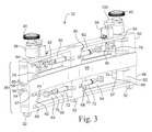
図3は、キャリッジ38と、回転式ワイヤブラシ40などの1つまたは複数のツール、機器またはセンサとを備えるツール32の一実施形態の透視図である。キャリッジがバッフルプレート上に着座したときにツール40が溶接部に隣接して配置されるように、キャリッジ38の高さ(h)は例えば6インチ(152mm)とすることができる。キャリッジ38、ならびにキャリッジ上のツール、機器およびセンサの幅(w)は例えば2インチ(50mm)、キャリッジの長さ(L)は例えば18インチ(0.45m)とすることができる。キャリッジは、その長さに沿って、シュラウドの周囲に従うわずかな弧を有することができる。
FIG. 3 is a perspective view of one embodiment of a
好ましくは、キャリッジ38の寸法、例えば50mm×152mm×450mmの寸法は、ケーブルによってツール32をシュラウドの頂部から間隙を通してバッフルプレートまで下ろすことができるように十分に小さい。具体的には、間隙を通してツールを下ろすときに、ツールを傾け、回転させ、横行させ、または他の態様で間隙を通してバッフルプレートまで下方へ移動させることにより、ツールを操作する必要があることがある。ツールのサイズが小さいと、ツールを、間隙内の障害物を通り越して移動させ、炉心シュラウドとジェットポンプアセンブリの間のバッフルプレート上に配置することができる。ツールが間隙を通って下方へ移動するとき、ケーブルはツールを支持し、間隙内のさまざまな障害物を通り越すようにツールを操作する。
Preferably, the dimensions of the
キャリッジは、それぞれ互いに対してスライドする梁(beam)である3本のレール46、48および50を含む。これらのレールはそれぞれ、炉心シュラウドの形状に従うわずかな弧を有する。下レール46はバッフルプレートレールであり、バッフルプレート上に載置されるホイールまたは足部52を含む。このバッフルプレートレールは、テレスコープ式横行レールと呼ばれる中間レール48上の溝56にはまる上縁54を有する。テレスコープ式横行レール48は、バッフルプレートレール46の上縁54を受け取る下溝56と、往復動レールと呼ばれる上レール50の下縁60を受け取る上溝58とを有するI形梁の形状を有することができる。
The carriage includes three
バッフルプレートレール46は、ツール、例えばワイヤブラシ40が炉心シュラウドの溶接部30に対する作業を実行している間、キャリッジを支持する。バッフルプレートレール46のホイール付きローラ52はバッフルプレート上に載置される。ツールが溶接部に対する作業を実行している間、バッフルプレートレールおよびそのローラは静止していることが好ましい。
The
一実施形態では、ツールが停止している間に、バッフルプレートレールおよびホイールが、バッフルプレート24を横切って、炉心シュラウドの周囲に沿って移動する。このバッフルプレートレール46(およびツール32全体)の移動は、バッフルプレートレールがバッフルプレート上の新たな位置に移動するインクリメント方式(incremental)とすることができる。この新たな位置にある間、バッフルプレートレールは静止したままであり、その間に、ツールが、炉心シュラウドの溶接部の一区間に対して作業を実行する。溶接部のその区間に対する作業が完了した後、バッフルプレートレールは、バッフルプレート上の別の位置へ移動して、溶接部上の新しい第2の位置にツールを再配置する。この別の位置で、ツールは溶接部に対する作業を実行し、その間、バッフルプレートレールは静止したままである。ツールが炉心シュラウドの周囲に沿って段階的に移動するときには、バッフルプレートレールを移動させてツールを再配置し、次いで、バッフルプレートレールが静止している間にツールが溶接部に対する作業を実行するこのシーケンスが繰り返される。
In one embodiment, the baffle plate rails and wheels move along the circumference of the core shroud across the
ワイヤブラシ40あるいは他のツールまた検査センサが溶接部30に対する作業または検査を実行することができるように、バッフルプレートレール46はキャリッジをブレーシング(bracing)する。例えば、溶接部を平滑にするために回転式ワイヤブラシ40が押し当てられている間、バッフルプレートレール46をブレーシングしてツール32を安定させることができる。ワイヤブラシと溶接部の間の力は、バッフルプレートレールのこのブレーシング作用によって打ち消さなければならない。ワイヤブラシに加わる力を打ち消すため、バッフルプレートレールから延出し、ジェットポンプアセンブリの壁に当接する1つまたは複数のブレーシングプレート64によって、バッフルプレートレールの内側ブレーシング面62を炉心シュラウドに対してブレーシングする。ブレーシングプレート(1つまたは複数)は、炉心シュラウドに対してバッフルプレートレールを半径方向内側へ押す。バッフルプレートレールが炉心シュラウドに対してしっかりと保持されるため、キャリッジおよびワイヤブラシは安定し、その結果、溶接部に対する作業を実行する間、ワイヤブラシは溶接部に力を加えることができる。
The
ブレーシングプレート64は、バッフルプレートレール46に枢動可能に取り付けることができる。バッフルプレートレールの長方形の中央開口68の片側のバッフルプレートレールの垂直縁67上にピボット継手66を配置することができる。ツール32が間隙22内を移動する間、ブレーシングプレート64およびその関連アクチュエータは開口68の中に引っ込められる。それぞれのブレーシングプレートの側縁がピボット継手66に取り付けられる。ブレーシングプレートは、実質的に開口68の全体を横切って延びることができ、引っ込められたときに開口内に収まることができる。ブレーシングプレートは、開口内に収容された第1の位置から、プレートの反対端70がツール32の外に延出した第2の位置に枢動することができる。プレート64の延出した反対端70は、ジェットポンプアセンブリに当接し、ツールを炉心シュラウドに対してしっかりと押すことが好ましい。具体的には、プレートの延出した反対端70がジェットポンプアセンブリに当接したときに、バッフルプレートレールの内側ブレーシング面62が炉心シュラウドに押し付けられる。内側ブレーシング面は、バッフルプレートレールの内壁とすることができ、またはブレーシングプレートの枢動運動と同時にピボット継手を軸に回転する突出カムとすることができる。このカムは、ブレーシングプレートが外側に枢動したときに、バッフルプレートレールの内壁よりも内側に突出する。このカムは、バッフルプレートレールの開口68内に引っ込み、ブレーシングプレートは内側へ枢動し、同じ開口内に引っ込む。ツール32上のこのカムまたは突起は炉心シュラウドに当接し、ツール32の残りの部分と炉心シュラウドの間にすき間を形成する。したがって、バッフルプレートレールの内壁に、横行レール48および往復動レール50を含むツール32の残りの部分よりも内側へ延出する枢動カムまたは突起があることが好ましい。
The bracing
ブレーシングプレート64を枢動させるアクチュエータ72は、一端がブレーシングプレートに枢動可能に接続され、反対端が、バッフルプレートレールの開口68の縁に枢動可能に接続された、液圧、空気圧または電気式の伸縮シャフトとすることができる。この伸縮シャフトが伸長すると、ブレーシングプレートは外側へ枢動し、このシャフトが収縮すると、ブレーシングプレートはバッフルプレートレールの開口68内へ引き込まれる。このアクチュエータは、炉心シュラウドの頂部にいるオペレータによって制御され、アクチュエータからオペレータまで信号線が延びる。この信号線は、ツールを操作するためにオペレータが使用する、ツール32に結合された制御ケーブルに含めることができる。
The
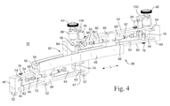
図4は、伸長位置にある溶接部検査/補修ツール32の透視図である。図4は、炉心シュラウドの方に向けられる、ツール32の内側の面を示している。この伸長位置では、テレスコープ式横行レール48が、バッフルプレートレール46の上縁54に沿って横方向に移動しており、その結果、テレスコープ式横行レールの長さのかなりの部分、例えばテレスコープ式横行レールの長さの50パーセント超、好ましくは75パーセント超が、バッフルプレートレールの一端よりも先に延びている。同様に、往復動レール50も、テレスコープ式横行レールの上溝58に沿って横方向に移動しており、その結果、往復動レールの長さのかなりの部分、例えば往復動レールの長さの50パーセント超、好ましくは75パーセント超が、テレスコープ式横行レールの一端よりも先に延びている。この伸長位置では、ツール32の長さ(L)を、非伸長位置(図3に示されている)においてレール46、48および50が互いに上下に重なっているときのツールの長さの2倍以上にすることができる。
FIG. 4 is a perspective view of the weld inspection /
横行レール48は、その側面に配置されたI形梁の形状を有する。横行レールの下面は、バッフルプレートレールの上縁54にスライド可能に載置される。横行レールの下面は、バッフルプレートレール上に載置されたときに横行レールが安定するようにバッフルプレートレールの上縁54に概ね従う下溝56を含む。下溝56の内面は、駆動モータ74に回転可能に取り付けられた歯車とかみ合う歯からなる軌道を含む。バッフルプレートレール46の上で横行レール48を前進させるため、駆動モータが横行レールを横方向に移動させる。上縁54と下溝56の間の接合部のキー(key)またはリッジ(ridge)は、横行レールが完全に伸ばされたときに横行レールがバッフルプレートレール46から落下しないことを保証する。
The
これらのレールがその下のレールの上をスライドするときには、歯車駆動モータがレールを駆動する。バッフルプレートレールを横切ってテレスコープ式横行レールを駆動するため、歯車モータ74は、中央開口68の側面など、バッフルプレートレール上に装着される。これらの駆動モータは、横行レール48の下溝56の歯軌道とかみ合う歯車76を回転させる。この歯軌道は、歯車モータ上の歯車76とかみ合うように例えば垂直に向けられる。駆動モータ74によって歯車が回転することにより、横行レール48はバッフルプレートレールに対して横方向に移動する。バッフルプレートレールのそれぞれの端部に向けて2つの駆動モータ74を配置することができる。バッフルプレートレール46を横切って横行レール48が移動することによって、横行レールが、図4に示すように、移動方向とは反対側のバッフルプレートレールの端の駆動モータ74を通り越して伸び、この駆動モータ74から外れるため、一般に2つの駆動モータが必要である。
When these rails slide on the rails below, the gear drive motor drives the rails. To drive the telescoping traverse rail across the baffle plate rail, the
同様に、往復動レール50上に歯車駆動モータ78が配置され、歯車駆動モータ78は、往復動レールの下縁60の歯車まで下方へ延びる。横行レール48は、往復動レール50の下縁60を受け取る上溝58を有する。上溝58は、往復動レールの中央の開口領域80内に装着された駆動モータ78の歯車とかみ合う歯の付いた軌道を含む。これらの歯車は、横行レールの上溝58の歯軌道とかみ合う。歯車駆動モータ78は、テレスコープ式横行レールを横切って往復動レール50を横方向に駆動する。歯車駆動モータ74および78は、炉心シュラウドの頂部にいるオペレータが制御することができる。それぞれの歯車モータと炉心シュラウドの頂部の制御システムの間に、信号線、例えば電線を引くことができる。
Similarly, a
往復動レール50は、バッフルプレートレール46のブレーシングプレート64と同様のブレーシングプレート82を有する。ブレーシングプレート82は、往復動レールの中央開口領域80内に配置される。ブレーシングプレートは、開口領域の反対端に装着されたピボット継手84に枢動可能に装着される。伸縮式アクチュエータ86は、一端が、それぞれのブレーシングプレート82に取り付けられ、他端が、往復動レールのセンターポスト88に取り付けられる。センターポスト88は、往復動レールの長方形のフレーム90にしっかりと取り付けられる。センターポストは、往復動レールのそれぞれの伸縮式アクチュエータ86の一端を支持する。バッフルプレートレール46のフレーム90にも同様のセンターポスト88が配置される。
The reciprocating
フレーム90およびセンターポスト88は、バッフルプレートレールおよび往復動レールに全体に堅い構造を提供することができる。同様に、テレスコープ式横行レールのI形梁構造も全体に堅い構造である。ツール32のフレーム、センターポストおよび他の構造構成要素を形成するために金属材料を使用することができる。金属材料はツールに構造的剛性を提供する。
往復動レール50の上部92は、回転式ワイヤブラシ40を含むことができるツールまたはセンサアセンブリを支持する。レール50の上部に、1つまたは複数のツールまたはセンサアセンブリを装着することができる。これらのアセンブリは、全てのアセンブリが、ワイヤブラシなどの同じツールまたはセンサを含んでもよく、またはワイヤブラシと溶接部検査センサなど、異なるツールおよびセンサを含んでもよい。それぞれのアセンブリは、昇降機構94と、往復動レールの中央開口領域80内に装着されたトーションモータ96とを含むことができる。昇降機構94は、炉心シュラウド上の磨き直す溶接部と同じ高さにワイヤブラシを配置するために、ワイヤブラシ(あるいは他のツールまたはセンサ)を垂直方向に移動させる。昇降機構は、トーションモータ96とかみ合う螺旋形のねじ山を有する伸長可能なシャフトとすることができる。オペレータは、トーションモータを作動させる制御システムを使用して、この伸長可能シャフトを上げ下げし、それによってブラシを所望の高さに配置するように昇降機構を制御する。伸長可能シャフトは、往復動レールの上部92に固定されたハウジングの中に支持することができる。トーションモータを使用して、スプラインが切られた昇降シャフトを枢動させ、それにより炉心シュラウドに対してブラシを移動させ、ブラシに圧力を加えることができる。炉心シュラウドに対するブラシの圧力を制御するため、トーションモータのトルクを調節することができる。
The
ワイヤブラシ40は、昇降機構の伸長可能シャフトの上端のブラケット100によって支持されたブラシ駆動モータ98によって駆動することができる。このブラシ駆動モータはワイヤブラシを回転させる。溶接部30に対してワイヤブラシを回転させると、溶接部の表面が平滑化され、溶接部上の金属ばりおよび他の小さな凹凸が除去される。溶接部を平滑にし、小さな凹凸を除去することで、溶接部が磨き直され、溶接部における亀裂の入りやすさが低減する。
The
ワイヤブラシ40が溶接部30を平滑にするときには、往復動レール50が、テレスコープ式レールを横切ってゆっくりと横方向に移動する。この移動により、ブラシは、溶接部の上を炉心シュラウドに沿って周囲方向に移動する。往復動レールは数サイクルにわたって左右に移動することができ、その間に、ブラシはわずかに異なる高さに、例えば約0.25インチ(10mm)垂直に移動する。この左右移動およびワイヤブラシの高さの調整は、ブラシが溶接部の全高に作用することを保証し、ブラシが溶接部の上を複数回通過することを可能にする。
When the
往復動レールのこの左右移動サイクルは、テレスコープ式レールがバッフルプレートレールの一端に保持されている間に実行することができる。そのサイクルが完了した後、テレスコープ式レールはバッフルプレートレールの他端まで移動し、往復動レールによって左右移動サイクルが再び実行される。テレスコープ式レールが横方向に移動することにより、ブラシは溶接部の周囲上の他の領域へ移動する。往復動レールが左右移動サイクルを実行し、テレスコープ式レールが、往復動レールを、バッフルプレートレールの1つの側から別の側へ再配置する間、バッフルプレートレール46は、ジェットポンプハウジングと炉心シュラウドの間にブレーシングされる。
This left / right cycle of the reciprocating rail can be performed while the telescoping rail is held at one end of the baffle plate rail. After the cycle is complete, the telescoping rail moves to the other end of the baffle plate rail and the left / right cycle is performed again by the reciprocating rail. As the telescoping rail moves laterally, the brush moves to other areas on the perimeter of the weld. While the reciprocating rail performs a left-right travel cycle and the telescoping rail repositions the reciprocating rail from one side of the baffle plate rail to another, the
図5は、伸長位置にある溶接部検査/補修ツール32の透視図であり、この図は、ジェットポンプアセンブリに面するキャリッジ38の外側の面を示している。操作に当たっては、溶接部検査/補修ツール32のホイールが、圧力容器10と炉心シュラウド18の間の間隙22内のバッフルプレート24上に載るような位置に、溶接部検査/補修ツール32を下ろす。溶接部検査/補修ツール32を下ろし、配置する間、レール46、48および50は、キャリッジ38の長さがこれらのレールのうちの単一のレールの長さに等しくなるように、互いに上下に重ねられる。ツール32は、ジェットポンプアセンブリのない領域34の上に下ろされることが好ましい。ツール32を下ろした制御ケーブルは、炉心シュラウドと一対のジェットポンプアセンブリ28の間でツールを操作する。ツール32のキャリッジ38の外側の面が、その一対のジェットポンプアセンブリ28の間に来たら、バッフルプレートレール46のブレーシングプレート64を延出させて、ブレーシングプレートがそれぞれ一方のジェットポンプアセンブリに当接するようにする。それぞれのプレート64が、この一対のジェットポンプアセンブリのうちの一方のアセンブリに当接すると、バッフルプレートレール上の内側ブレーシング面62が炉心シュラウドにしっかりと押し付けられる。ブレーシングプレートは、テレスコープ式横行レールおよび往復動レールが移動するときおよびブラシ40が溶接部を平滑にするときに、炉心シュラウドに対してバッフルプレートレールをしっかりと強く保持する十分な力を加える。
FIG. 5 is a perspective view of weld inspection /
溶接部をブラシ研磨し、テレスコープ式横行レールおよび往復動レールを移動させ、ブラシが溶接部を平滑にする間、バッフルプレートレール46は静止したままである。バッフルプレートレールが静止している間に、ブラシが、ブラシが届く溶接部の区間の平滑化を完了した後、キャリッジ38は、バッフルプレート上の隣接する一対のジェットポンプアセンブリ間の別の位置へのバッフルプレートレールの移動を開始させる。
The
バッフルプレートレールを移動させる前に、テレスコープ式横行レールおよび往復動レールは(図3に示すように)バッフルプレートレールの上に重ねられる。その後、往復動レール50上のブレーシングプレート82を延出させて、バッフルプレートレール46上のブレーシングプレート64が当接しているのと同じ一対のジェットポンプアセンブリに当接させる。ジェットポンプアセンブリとブレーシングプレート82との間のこの当接係合は、往復動レールを静止位置に固定する。往復動レール上のブレーシングプレート82がその一対のジェットポンプアセンブリに当接した後、バッフルプレートレール46上のブレーシングプレート64をレールの開口68内へ引っ込める。これらのプレート64を引っ込めると、間隙22に沿って周囲方向に、バッフルプレート24を横切ってバッフルプレートレールを移動させることが可能になる。往復動レール50を静止状態に維持し、その間に、レール駆動モータ78が、テレスコープ式横行レール48を往復動レールから横方向に伸ばし、レール駆動モータ74が、バッフルプレートレール46をテレスコープ式横行レール48から横方向に延ばす。
Prior to moving the baffle plate rail, the telescoping traverse rail and reciprocating rail are overlaid on the baffle plate rail (as shown in FIG. 3). Thereafter, the bracing
テレスコープ式横行レールおよびバッフルプレートレールが往復動レールから完全に伸ばされたとき、キャリッジ38は図4および5に示すような外観を呈する。例えばレール46、48、50のうちの1つのレールの長さ(L)に等しい距離だけバッフルプレートレール46を伸ばすことによって、バッフルプレートレールは再び、一対のジェットポンプアセンブリ間に配置される。これらのレールの長さは、環状間隙22内のジェットポンプアセンブリ間の距離に等しいことが好ましい。バッフルプレートレール46を伸ばして、次のジェットポンプアセンブリ間に置いた後、バッフルプレートレールのブレーシングプレート64を延出させて、これらの次のジェットポンプアセンブリに当接させ、バッフルプレートレールを再び炉心シュラウドに対して固定する。バッフルプレートレールを固定した後、前の一対のジェットポンプアセンブリから往復動レール50内へ、ブレーシングプレート82を引っ込める。
When the telescoping traverse rail and baffle plate rail are fully extended from the reciprocating rail, the
ブレーシングプレート82を引っ込めると、往復動レール50は、炉心シュラウド上の溶接部の別の区間を平滑にするために左右に自由に移動することができる。(i)一対のジェットポンプアセンブリと炉心シュラウドの間にバッフルプレートレールをブレーシングし、(ii)テレスコープ式横行レールおよび往復動レールを横方向に移動させることによってブラシ、ツールまたはセンサを前進させることにより、炉心シュラウドの溶接部または他の部分を平滑にし、検査し、または他の作業を実行し、(iii)前記一対のジェットポンプアセンブリと炉心シュラウドの間に往復動レールをブレーシングし、(iv)バッフルプレートレールのブレースを解放し、バッフルプレートレールおよびテレスコープ式横行レールを、炉心シュラウドの周囲の次の位置まで伸ばすシーケンスを繰り返して、溶接部検査/補修ツール32を、バッフルプレートの上で、炉心シュラウドの周囲に沿って前進させる。炉心シュラウドの周囲に沿ったツール32の移動が完了したら、ツールを、バッフルプレート24上の障害物のない位置34の上に置き、圧力容器と炉心シュラウドの間の間隙から外へ引き上げる。
When the bracing
現時点の最も実際的で好ましい実施形態であると考えられるものに関して本発明を説明したが、本発明は、開示された実施形態に限定されないことを理解されたい。反対に、本発明は、添付の特許請求項の趣旨および範囲に含まれるさまざまな変更および均等の構成を包含することが意図されている。 Although the present invention has been described with respect to what is considered to be the most practical and preferred embodiments at the present time, it is to be understood that the invention is not limited to the disclosed embodiments. On the contrary, the invention is intended to cover various modifications and equivalent arrangements included within the spirit and scope of the appended claims.
10 圧力容器
12 底部ヘッド
14 取外し可能な頂部ヘッド
16 圧力容器の側壁
18 炉心シュラウド
20 炉心
22 環状間隙
24 バッフルプレート(ポンプデッキ)
26 バッフルプレートの開口
28 ジェットポンプアセンブリ
30 溶接部
32 溶接部検査/補修ツール
34 ジェットポンプアセンブリのないバッフルプレート上の位置
36 円形カバー
38 キャリッジ
40 ブラシ
46 バッフルプレートレール
48 テレスコープ式横行レール
50 往復動レール
52 バッフルプレートレール上のホイールまたは足部
54 バッフルプレートレールの上縁
56 横行レールの下溝
58 横行レールの上溝
60 往復動レールの下溝
62 内側ブレーシング面
64 ブレーシングプレート
66 ピボット継手
68 バッフルプレートレールの中央開口
70 ブレーシングプレートの反対端
72 ブレーシングプレートのアクチュエータ
74 バッフルプレートレール上のレール駆動モータ
76 駆動歯車
78 往復動レール上のレール駆動モータ
80 往復動レールの開口領域
82 往復動レール内のブレーシングプレート
84 ピボット継手
86 伸縮式アクチュエータ
88 レールのセンターポスト
90 フレーム
92 往復動レールの上部
94 昇降機構
96 トーションモータ
98 ブラシ駆動モータ
100 昇降機構上のトーションブラケット
10 Pressure Vessel 12
26 Baffle plate opening 28
68 Central opening of
Claims (6)
前記炉心シュラウドと前記原子炉圧力容器との間の間隙内のバッフルプレート(24)に接するように適合された下面を有するバッフルプレートレール(46)と、
前記バッフルプレートレールの上部領域にスライド可能に結合されたテレスコープ式レール(48)と、
前記テレスコープ式レールの上部領域にスライド可能に結合され、溶接部コンディショニングツール(40)、溶接部検査センサおよび溶接部補修装置のうちの少なくとも1つを含む往復動レール(50)と
を備え、
前記バッフルプレートレール(46)が、前記バッフルプレートレールに隣接する閉位置と、前記バッフルプレートレール(46)の両端部のそれぞれを軸として前記バッフルプレートレールから延出する延出位置とを有する一対の延出可能ブレース(64)を含む、
るアセンブリ(32)。 An assembly (32) adapted to access a circumferentially extending weld (30) surrounding the core shroud (18) of the reactor core (20) contained within the reactor pressure vessel (10). And
A baffle plate rail (46) having a lower surface adapted to contact a baffle plate (24) in a gap between the core shroud and the reactor pressure vessel;
A telescoping rail (48) slidably coupled to the upper region of the baffle plate rail;
A reciprocating rail (50) slidably coupled to an upper region of the telescoping rail and including at least one of a weld conditioning tool (40), a weld inspection sensor and a weld repair device;
A pair of the baffle plate rail (46) having a closed position adjacent to the baffle plate rail and an extended position extending from the baffle plate rail about each end of the baffle plate rail (46). Including an extendable brace (64),
Assembly (32).
A weld conditioning tool (40) includes a brush drive motor (98) and a brush (40) rotatably driven by the brush drive motor, the brush moving to align with the surrounding weld. Assembly (32) according to claim 1, characterized in that it is possible.
Applications Claiming Priority (2)
| Application Number | Priority Date | Filing Date | Title |
|---|---|---|---|
| US12/415,385 | 2009-03-31 | ||
| US12/415,385 US8291564B2 (en) | 2009-03-31 | 2009-03-31 | Telescoping tool assembly and method for refurbishing welds of a core shroud of a nuclear reactor vessel |
Publications (3)
| Publication Number | Publication Date |
|---|---|
| JP2010243492A JP2010243492A (en) | 2010-10-28 |
| JP2010243492A5 JP2010243492A5 (en) | 2012-11-22 |
| JP5436306B2 true JP5436306B2 (en) | 2014-03-05 |
Family
ID=42782350
Family Applications (1)
| Application Number | Title | Priority Date | Filing Date |
|---|---|---|---|
| JP2010080359A Active JP5436306B2 (en) | 2009-03-31 | 2010-03-31 | Retractable tool assembly and method for refurbishing a reactor vessel core shroud weld |
Country Status (2)
| Country | Link |
|---|---|
| US (1) | US8291564B2 (en) |
| JP (1) | JP5436306B2 (en) |
Families Citing this family (11)
| Publication number | Priority date | Publication date | Assignee | Title |
|---|---|---|---|---|
| DE102008014544A1 (en) * | 2008-03-15 | 2009-09-17 | Areva Np Gmbh | Device for repairing a damaged area in a submerged wall area of a container or basin |
| US10074448B2 (en) * | 2010-10-21 | 2018-09-11 | Westinghouse Electric Company Llc | Submersible machine structured to carry a tool to a limited access location within a nuclear containment |
| US8925168B2 (en) * | 2011-12-01 | 2015-01-06 | Akshay Srivatsan | Apparatus and method for repairing a surface submerged in liquid by creating a workable space |
| JP5688383B2 (en) * | 2012-01-31 | 2015-03-25 | 日立Geニュークリア・エナジー株式会社 | Shroud support repair method and repair device |
| US9437333B2 (en) * | 2012-10-09 | 2016-09-06 | Westinghouse Electric Company Llc | Apparatus and method to control sensor position in limited access areas within a nuclear reactor |
| ES2640762T3 (en) * | 2012-10-09 | 2017-11-06 | Westinghouse Electric Company Llc | Apparatus and procedure for inspecting, modifying or repairing core envelopes of a nuclear reactor |
| US9318226B2 (en) | 2012-10-09 | 2016-04-19 | Westinghouse Electric Company Llc | Apparatus and method to inspect, modify, or repair nuclear reactor core shrouds |
| DE102013112136B3 (en) * | 2013-11-05 | 2015-01-15 | Areva Gmbh | Device for repairing damage to the bottom of a container filled with water |
| US10311986B2 (en) * | 2014-01-15 | 2019-06-04 | Ge-Hitachi Nuclear Energy Americas Llc | Inspection apparatus and method of inspecting a reactor component using the same |
| CN105500005B (en) * | 2015-11-26 | 2017-11-21 | 浙江华顺金属材料有限公司 | A kind of stainless steel band rounding side deburring dual-purpose apparatus |
| CN106736588A (en) * | 2017-01-17 | 2017-05-31 | 宜兴市科兴合金材料有限公司 | A kind of topping machanism for Mo wafer |
Family Cites Families (11)
| Publication number | Priority date | Publication date | Assignee | Title |
|---|---|---|---|---|
| FR2381657A1 (en) * | 1977-02-24 | 1978-09-22 | Commissariat Energie Atomique | SELF-PROPELLED VEHICLE WITH ARTICULATED ARMS |
| JP3851683B2 (en) * | 1996-06-10 | 2006-11-29 | 株式会社東芝 | In-reactor inspection device |
| JP3604535B2 (en) * | 1997-07-17 | 2004-12-22 | 株式会社東芝 | Reactor inspection and repair equipment |
| US5930316A (en) * | 1998-05-29 | 1999-07-27 | General Electric Company | Shroud support ultrasonic examination apparatus |
| JP2000075080A (en) * | 1998-08-31 | 2000-03-14 | Toshiba Corp | Jet pump inspection device and treatment device |
| JP4490550B2 (en) * | 2000-04-14 | 2010-06-30 | 株式会社東芝 | Modular underwater repair device and repair method |
| JP4262450B2 (en) * | 2002-06-28 | 2009-05-13 | 日立Geニュークリア・エナジー株式会社 | Reactor narrow part repair system |
| US7092477B2 (en) * | 2002-10-01 | 2006-08-15 | Westinghouse Electric Co Llc | BWR inspection manipulator |
| US7649970B2 (en) * | 2005-08-04 | 2010-01-19 | General Electric Company | Repair apparatus for a nuclear reactor shroud |
| JP5028023B2 (en) * | 2006-04-26 | 2012-09-19 | 日立Geニュークリア・エナジー株式会社 | Preventive maintenance method and preventive maintenance device for reactor annulus |
| US7769123B2 (en) * | 2007-06-20 | 2010-08-03 | Ge-Hitachi Nuclear Energy Americas, Llc | Inspection, maintenance, and repair apparatuses and methods for nuclear reactors |
-
2009
- 2009-03-31 US US12/415,385 patent/US8291564B2/en not_active Expired - Fee Related
-
2010
- 2010-03-31 JP JP2010080359A patent/JP5436306B2/en active Active
Also Published As
| Publication number | Publication date |
|---|---|
| US8291564B2 (en) | 2012-10-23 |
| JP2010243492A (en) | 2010-10-28 |
| US20100242247A1 (en) | 2010-09-30 |
Similar Documents
| Publication | Publication Date | Title |
|---|---|---|
| JP5436306B2 (en) | Retractable tool assembly and method for refurbishing a reactor vessel core shroud weld | |
| KR101143747B1 (en) | Welding positioner for the machine welding | |
| CN101780583B (en) | Platform lifting type cylinder body circular seam and longitudinal seam welding machine | |
| CN201592305U (en) | Platform-lifting type cylinder circumferential seam/longitudinal seam welding machine | |
| JP2010237213A (en) | Manipulator for remote operation in nuclear reactor vessel | |
| JP2859125B2 (en) | Preventive maintenance method in reactor vessel and its preventive maintenance device | |
| JP2002168992A (en) | Method for repair of inside reactor pressure vessel, and repairing device | |
| JP3514875B2 (en) | Remote furnace working apparatus and method | |
| JP3530005B2 (en) | Preventive maintenance device and preventive maintenance method for structural members inside reactor pressure vessel | |
| JP5480051B2 (en) | Surface cleaning equipment for concrete walls | |
| JP2022172308A (en) | Reciprocation apparatus | |
| JP2003337192A (en) | Inspection and preventive maintenance apparatus for structure within reactor pressure vessel, and inspection method | |
| JP5914011B2 (en) | Concrete wall surface cleaning method | |
| JP3905051B2 (en) | Repair inspection system for structure surface | |
| KR101080937B1 (en) | Maintenance System for CRDM Nozzles of Reactor Head | |
| KR101742218B1 (en) | Maintenance apparatus of leg of floating structure | |
| CN105436905B (en) | Ellipsoid store-vessel bottom ring flange installs equipment additional | |
| CN109048601B (en) | Full-automatic polishing machine for furnace barrel | |
| JP6250488B2 (en) | Water jet peening apparatus and water jet peening method | |
| JP6651823B2 (en) | Manipulator device | |
| JPH09211182A (en) | Device and method for remote-control work in reactor | |
| JP6839965B2 (en) | Manipulator device | |
| JP4043668B2 (en) | Surface processing equipment for in-reactor installation equipment | |
| KR101488712B1 (en) | moving platform inspecting and maintaining apparatus for nuclear reactor | |
| JP4987388B2 (en) | Device access device to the annulus |
Legal Events
| Date | Code | Title | Description |
|---|---|---|---|
| A521 | Request for written amendment filed |
Free format text: JAPANESE INTERMEDIATE CODE: A523 Effective date: 20121003 |
|
| A621 | Written request for application examination |
Free format text: JAPANESE INTERMEDIATE CODE: A621 Effective date: 20121003 |
|
| A871 | Explanation of circumstances concerning accelerated examination |
Free format text: JAPANESE INTERMEDIATE CODE: A871 Effective date: 20121003 |
|
| A975 | Report on accelerated examination |
Free format text: JAPANESE INTERMEDIATE CODE: A971005 Effective date: 20121017 |
|
| A131 | Notification of reasons for refusal |
Free format text: JAPANESE INTERMEDIATE CODE: A131 Effective date: 20121030 |
|
| A521 | Request for written amendment filed |
Free format text: JAPANESE INTERMEDIATE CODE: A523 Effective date: 20130128 |
|
| A131 | Notification of reasons for refusal |
Free format text: JAPANESE INTERMEDIATE CODE: A131 Effective date: 20130507 |
|
| TRDD | Decision of grant or rejection written | ||
| A01 | Written decision to grant a patent or to grant a registration (utility model) |
Free format text: JAPANESE INTERMEDIATE CODE: A01 Effective date: 20131112 |
|
| A61 | First payment of annual fees (during grant procedure) |
Free format text: JAPANESE INTERMEDIATE CODE: A61 Effective date: 20131210 |
|
| R150 | Certificate of patent or registration of utility model |
Ref document number: 5436306 Country of ref document: JP Free format text: JAPANESE INTERMEDIATE CODE: R150 Free format text: JAPANESE INTERMEDIATE CODE: R150 |
|
| R250 | Receipt of annual fees |
Free format text: JAPANESE INTERMEDIATE CODE: R250 |
|
| R250 | Receipt of annual fees |
Free format text: JAPANESE INTERMEDIATE CODE: R250 |
|
| R250 | Receipt of annual fees |
Free format text: JAPANESE INTERMEDIATE CODE: R250 |
|
| R250 | Receipt of annual fees |
Free format text: JAPANESE INTERMEDIATE CODE: R250 |
|
| R250 | Receipt of annual fees |
Free format text: JAPANESE INTERMEDIATE CODE: R250 |
|
| R250 | Receipt of annual fees |
Free format text: JAPANESE INTERMEDIATE CODE: R250 |
|
| R250 | Receipt of annual fees |
Free format text: JAPANESE INTERMEDIATE CODE: R250 |
|
| R250 | Receipt of annual fees |
Free format text: JAPANESE INTERMEDIATE CODE: R250 |