JP5433238B2 - Gear device and swing gear device - Google Patents
Gear device and swing gear device Download PDFInfo
- Publication number
- JP5433238B2 JP5433238B2 JP2009004859A JP2009004859A JP5433238B2 JP 5433238 B2 JP5433238 B2 JP 5433238B2 JP 2009004859 A JP2009004859 A JP 2009004859A JP 2009004859 A JP2009004859 A JP 2009004859A JP 5433238 B2 JP5433238 B2 JP 5433238B2
- Authority
- JP
- Japan
- Prior art keywords
- pin
- gear
- groove
- holding groove
- tooth
- Prior art date
- Legal status (The legal status is an assumption and is not a legal conclusion. Google has not performed a legal analysis and makes no representation as to the accuracy of the status listed.)
- Active
Links
Images


Classifications
-
- B—PERFORMING OPERATIONS; TRANSPORTING
- B62—LAND VEHICLES FOR TRAVELLING OTHERWISE THAN ON RAILS
- B62D—MOTOR VEHICLES; TRAILERS
- B62D5/00—Power-assisted or power-driven steering
- B62D5/008—Changing the transfer ratio between the steering wheel and the steering gear by variable supply of energy, e.g. by using a superposition gear
-
- F—MECHANICAL ENGINEERING; LIGHTING; HEATING; WEAPONS; BLASTING
- F16—ENGINEERING ELEMENTS AND UNITS; GENERAL MEASURES FOR PRODUCING AND MAINTAINING EFFECTIVE FUNCTIONING OF MACHINES OR INSTALLATIONS; THERMAL INSULATION IN GENERAL
- F16H—GEARING
- F16H1/00—Toothed gearings for conveying rotary motion
- F16H1/28—Toothed gearings for conveying rotary motion with gears having orbital motion
- F16H1/32—Toothed gearings for conveying rotary motion with gears having orbital motion in which the central axis of the gearing lies inside the periphery of an orbital gear
- F16H1/321—Toothed gearings for conveying rotary motion with gears having orbital motion in which the central axis of the gearing lies inside the periphery of an orbital gear the orbital gear being nutating
-
- F—MECHANICAL ENGINEERING; LIGHTING; HEATING; WEAPONS; BLASTING
- F16—ENGINEERING ELEMENTS AND UNITS; GENERAL MEASURES FOR PRODUCING AND MAINTAINING EFFECTIVE FUNCTIONING OF MACHINES OR INSTALLATIONS; THERMAL INSULATION IN GENERAL
- F16H—GEARING
- F16H55/00—Elements with teeth or friction surfaces for conveying motion; Worms, pulleys or sheaves for gearing mechanisms
- F16H55/02—Toothed members; Worms
- F16H55/10—Constructively simple tooth shapes, e.g. shaped as pins, as balls
-
- F—MECHANICAL ENGINEERING; LIGHTING; HEATING; WEAPONS; BLASTING
- F16—ENGINEERING ELEMENTS AND UNITS; GENERAL MEASURES FOR PRODUCING AND MAINTAINING EFFECTIVE FUNCTIONING OF MACHINES OR INSTALLATIONS; THERMAL INSULATION IN GENERAL
- F16H—GEARING
- F16H35/00—Gearings or mechanisms with other special functional features
- F16H35/008—Gearings or mechanisms with other special functional features for variation of rotational phase relationship, e.g. angular relationship between input and output shaft
-
- Y—GENERAL TAGGING OF NEW TECHNOLOGICAL DEVELOPMENTS; GENERAL TAGGING OF CROSS-SECTIONAL TECHNOLOGIES SPANNING OVER SEVERAL SECTIONS OF THE IPC; TECHNICAL SUBJECTS COVERED BY FORMER USPC CROSS-REFERENCE ART COLLECTIONS [XRACs] AND DIGESTS
- Y10—TECHNICAL SUBJECTS COVERED BY FORMER USPC
- Y10T—TECHNICAL SUBJECTS COVERED BY FORMER US CLASSIFICATION
- Y10T74/00—Machine element or mechanism
- Y10T74/19—Gearing
- Y10T74/19642—Directly cooperating gears
- Y10T74/1966—Intersecting axes
Abstract
Description
本発明は、歯車装置および揺動歯車装置に関する。 The present invention relates to a gear device and a rocking gear device.
歯車装置には、2つの傘歯車を噛み合わせたものがある(例えば、特許文献1参照)。特許文献1では、第1および第2の歯車が噛み合わされており、第1歯車に対して第2歯車が傾いている。第1歯車には、複数の溝が形成されており、溝から突出するようにコロが配置されている。このコロによって、半円筒状の凸歯が形成されている。一方、第2歯車には、複数の溝が形成されており、半円溝状の凹歯が形成されている。そして、第1歯車が回転すると、第1歯車の一部の凸歯と第2歯車の一部の凹歯とが噛み合い、第1歯車が第2歯車を回転させる。
There is a gear device in which two bevel gears are meshed (for example, see Patent Document 1). In
ところで、凸歯を構成するコロが第1歯車の溝から浮き上がったり抜けたりする(歯飛びする)ことは、トルクの抜けや異音の発生につながり、好ましくない。しかしながら、特許文献1では、コロを第1歯車の溝に積極的に押し付けることは意図されておらず、コロが第1歯車から浮き上がったり抜けたりすることを防ぐのに必ずしも十分とはいえない。
By the way, it is not preferable that the rollers constituting the convex teeth are lifted or removed from the groove of the first gear (missing teeth), resulting in torque loss and abnormal noise. However,
本発明は、かかる背景のもとでなされたもので、歯を構成する部材の浮き上がりや抜けを防止できる歯車装置および揺動歯車装置を提供することを目的とする。 The present invention has been made under such a background, and an object of the present invention is to provide a gear device and a rocking gear device capable of preventing a member constituting a tooth from being lifted and removed.
上記目的を達成するため、本発明は、第1の軸線(Z1)の回りに回転可能な第1の歯車(20,22)と、第1の軸線に対して傾斜する第2の軸線(Z2)の回りに回転可能とされ第1の歯車と動力伝達可能に噛み合う第2の歯車(39)とを備え、上記第1および第2の歯車の一方(20,22)は、当該一方の歯車の軸線(Z1)を中心に放射状に配置された複数の保持溝(79,109;79A)と、各保持溝に保持され上記第1および第2の歯車の上記一方の歯(81,111)をそれぞれ構成する複数のピン(77,87;77A)とを含み、上記第1および第2の歯車の他方(39)は、当該他方の歯車の軸線(Z2)を中心に放射状に配置され上記ピンに係合可能な複数の歯溝(80,110;80A)を有し、保持溝および歯溝からピンが受ける力(F1,F2)の合力が、ピンを保持溝側に付勢するようにしてあり、上記ピンの中心軸線(J1)および上記第1の軸線を含む基準平面(101)と、上記保持溝の内面(79b)から上記ピンと上記保持溝の内面との接触点(99c)に作用する力(F1)の作用線とがなす角である第1の接触角βは、上記基準平面と、歯溝の内面(80b)から上記ピンと上記歯溝の内面との接触点(100c)に作用する力(F2)の作用線とがなす角である第2の接触角αよりも大きく、上記ピンと上記歯溝との摩擦係数をμとしたときに(β−α)>2×tan-1(μ)が成立するように上記接触角βおよびαのそれぞれを設定することにより、上記歯溝からピンが受ける力(F2)がピンを保持溝およびピンの接触点(99c,99d)回りに回転させる第1のモーメント(M1)は、歯溝の内面に対するピンの摩擦力(F3)がピンを上記保持溝およびピンの接触点回りに回転させる第2のモーメント(M2)よりも大きくされていることを特徴とする歯車装置(78,88)を提供するものである(請求項1)。 In order to achieve the above object, the present invention provides a first gear (20, 22) rotatable around a first axis (Z1) and a second axis (Z2) inclined with respect to the first axis. ) And a second gear (39) meshing with the first gear so as to be able to transmit power, and one of the first and second gears (20, 22) is the one gear. A plurality of holding grooves (79, 109; 79A) arranged radially about the axis (Z1) of the first and second teeth (81, 111) of the first and second gears held in the holding grooves And the other of the first and second gears (39) is arranged radially with respect to the axis (Z2) of the other gear. A plurality of tooth grooves (80, 110; 80A) engageable with the pin, Resultant force of the force (F1, F2) which pin receives from the tooth groove is Yes so as to urge the pin into the holding groove side, the reference plane (101 including a central axis (J1) and the first axis of the pin a), the first contact angle with the line of action which is the angle between the inner surface of the holding groove (contact point from 79b) and the inner surface of the pin and the holding groove (force acting on 99c) (F1) beta is A second contact angle that is an angle formed by the reference plane and a line of action of the force (F2) acting on the contact point (100c) between the pin and the inner surface of the tooth gap from the inner surface (80b) of the tooth groove. The contact angles β and α are set so that (β−α)> 2 × tan −1 (μ) is established when the friction coefficient between the pin and the tooth gap is μ and is larger than α. As a result, the force (F2) received by the pin from the tooth groove causes the pin to hold the pin and the contact point of the pin (9 c, the first moment (M1 to rotate the 99d) around), the second moment frictional force of the pin against the inner surface of the tooth spaces (F3) rotates the pin contact points around the retaining groove and the pin (M2 The gear device (78, 88) is characterized in that it is made larger than (1).
本発明によれば、保持溝および歯溝からピンが受ける力の合力が、ピンを保持溝側に付勢するようにしてあることにより、ピンを保持溝から外れないようにすることができる。したがって、歯を構成するピンの浮き上がりや抜けを防止できる。その結果、トルクの抜けや異音の発生を防止できる。 According to the present invention, since the resultant force of the pin receives from the holding groove and the tooth groove urges the pin toward the holding groove, the pin can be prevented from being detached from the holding groove. Accordingly, it is possible to prevent the pins constituting the teeth from being lifted up or pulled out. As a result, torque loss and abnormal noise can be prevented.
また、保持溝からピンに作用する力のうち、保持溝から歯溝に向かう方向の成分を相対的に低くできるとともに、歯溝からピンに作用する力のうち、歯溝から保持溝に向かう方向の成分を相対的に高くできる。これにより、上記2つの成分の和は、歯溝から保持溝に向かう方向を向くものとなり、ピンを保持溝に確実に付勢することができる。 Further , among the forces acting on the pin from the holding groove, the component in the direction from the holding groove to the tooth groove can be relatively lowered, and among the forces acting on the pin from the tooth groove, the direction from the tooth groove to the holding groove Can be made relatively high. As a result, the sum of the two components is directed in the direction from the tooth groove toward the holding groove, and the pin can be reliably biased toward the holding groove.
また、第1のモーメントは、ピンを保持溝側に向けて付勢するモーメントであり、第2のモーメントは、ピンを保持溝から抜けさせるように働くモーメントである。この第1のモーメントが第2のモーメントよりも大きくされていることにより、第1および第2のモーメントの和は、ピンを保持溝側に向けて付勢するモーメントとなり、ピンを保持溝から抜けることをより確実に防止できる。 The first moment is a moment for urging the pin retaining groove side, the second moment is the moment acting to cause exit pin from the retention groove. Since the first moment is made larger than the second moment, the sum of the first and second moments becomes a moment for urging the pin toward the holding groove, and the pin comes out of the holding groove. This can be prevented more reliably.
また、本発明において、上記歯車装置を2つ備え、2つの第1の歯車は、2つの第2の歯車を挟んで配置されており、上記2つの第2の歯車は、互いの軸線が合致するように配置され第2の軸線の回りに同行回転可能に連結されている場合がある(請求項2)。
In the present invention, the two gear devices are provided, the two first gears are arranged with the two second gears sandwiched therebetween, and the two second gears have their axes aligned with each other. around the arranged second axis such that there may have been interconnected rotatably together (claim 2).
この場合、2つの第2の歯車が2つの第1の歯車に対して揺動運動する揺動歯車装置において、各ピンが対応する保持溝から浮き上がったり抜けたりすることを確実に防止できる。 In this case, in the oscillating gear device in which the two second gears oscillate with respect to the two first gears, each pin can be reliably prevented from being lifted or removed from the corresponding holding groove.
なお、上記において、括弧内の数字等は、後述する実施の形態における対応構成要素の参照符号を表すものであるが、これらの参照符号により特許請求の範囲を限定する趣旨ではない。 In the above description, numbers in parentheses represent reference numerals of corresponding components in the embodiments described later, but the scope of the claims is not limited by these reference numerals.
本発明の好ましい実施の形態を添付図面を参照しつつ説明する。 Preferred embodiments of the present invention will be described with reference to the accompanying drawings.
図1は、本発明の一実施の形態にかかる伝達比可変機構を備える車両用操舵装置1の概略構成を示す模式図である。図1を参照して、車両用操舵装置1は、ステアリングホイール等の操舵部材2に付与された操舵トルクを、操舵軸としてのステアリングシャフト3等を介して左右の転舵輪4L,4Rのそれぞれに与えて転舵を行うものである。この車両用操舵装置1は、操舵部材2の操舵角θ1に対する転舵輪の転舵角θ2の比としての伝達比θ2/θ1を変更することのできるVGR(Variable Gear Ratio)機能を有している。
FIG. 1 is a schematic diagram showing a schematic configuration of a
車両用操舵装置1は、操舵部材2と、操舵部材2に連なるステアリングシャフト3とを有している。ステアリングシャフト3は、互いに同軸上に配置された第1〜第3の軸としての第1〜第3のシャフト11〜13を含んでいる。第1〜第3のシャフト11〜13のそれぞれの中心軸線は、当該第1〜第3のシャフト11〜13の回転軸線でもある。
The
第1のシャフト11の一端に操舵部材2が同行回転可能に連結されている。第1のシャフト11の他端と第2のシャフト12の一端とは、伝達比可変機構5を介して差動回転可能に連結されている。第2のシャフト12と第3のシャフト13とは、トーションバー14を介して所定の範囲内で弾性的に相対回転可能、且つ動力伝達可能に連結されている。
A
第3のシャフト13は、自在継手7、中間軸8、自在継手9および転舵機構10等を介して、転舵輪4L,4Rと連なっている。
The
転舵機構10は、自在継手9に連なるピニオン軸15と、ピニオン軸15の先端のピニオン15aに噛み合うラック16aを有し車両の左右方向に延びる転舵軸としてのラック軸16とを有している。ラック軸16の一対の端部のそれぞれにタイロッド17L,17Rを介してナックルアーム18L,18Rが連結されている。
The steered
上記の構成により、操舵部材2の回転は、ステアリングシャフト3等を介して転舵機構10に伝達される。転舵機構10では、ピニオン15aの回転がラック軸16の軸方向の運動に変換される。ラック軸16の軸方向の運動は、各タイロッド17L,17Rを介して対応するナックルアーム18L,18Rに伝えられ、これらのナックルアーム18L,18Rがそれぞれ回動する。これにより、各ナックルアーム18L,18Rに連結された対応する転舵輪4L,4Rがそれぞれ操向する。
With the above configuration, the rotation of the
伝達比可変機構5は、ステアリングシャフト3の第1および第2のシャフト11,12間の回転伝達比(伝達比θ2/θ1)を変更するためのものであり、ニューテーションギヤ機構とされている。この伝達比可変機構5は、第1のシャフト11の他端に設けられた入力部材20と、第2のシャフト12の一端に設けられた出力部材22と、入力部材20と出力部材22との間に介在する中間部材としての軌道輪ユニット39と、を含んでいる。
The transmission
入力部材20は、操舵部材2および第1のシャフト11とはトルク伝達可能に連結されている。出力部材22は、第2のシャフト12とはトルク伝達可能に連結されている。第1の軸線Z1は、入力部材20および出力部材22の中心軸線および回転軸線である。
The
出力部材22は、第2のシャフト12や転舵機構10等を介して転舵輪4L,4Rに連なっている。
The
上記の軌道輪ユニット39は、第1の軌道輪としての内輪391と、第2の軌道輪としての外輪392と、内輪391および外輪392間に介在する玉等の転動体393とを含んでおり、玉軸受を構成している。
The
転動体393としては、玉以外にも、円筒ころ、針状ころ、円錐ころを用いることができる。また、転動体393は、単列に配置されていてもよいし、複列に配置されていてもよい。複列にすると、外輪392に対する内輪391の倒れを防止するのに好適である。複列のものとして、複列アンギュラ軸受を例示できる。
As the rolling
内輪391は、入力部材20と出力部材22とを差動回転可能に連結するものである。内輪391および外輪392は、第1の軸線Z1に対して傾斜する中心軸線としての第2の軸線Z2を有している。第2の軸線Z2は、第1の軸線Z1に対して所定の傾斜角度をなして傾斜している。内輪391は、転動体393を介して外輪392に回転可能に支持されていることにより、第2の軸線Z2の回りを回転可能であり、また、外輪392を駆動するためのアクチュエータとしての電動モータである伝達比可変機構用モータ23が駆動されることに伴い、第1の軸線Z1の回りを回転可能である。内輪391および外輪392は、第1の軸線Z1回りにコリオリ運動(首振り運動)可能である。
The
伝達比可変機構用モータ23は、軌道輪ユニット39の径方向外方に配置されており、第1の軸線Z1が中心軸線とされている。伝達比可変機構用モータ23は、第1の軸線Z1回りに関する外輪392の回転数を変更することにより、伝達比θ2/θ1を変更する。
The transmission ratio
伝達比可変機構用モータ23は、例えばブラシレスモータからなり、軌道輪ユニット39の外輪392を保持するロータ231と、このロータ231を取り囲むとともにステアリングコラムとしてのハウジング24に固定されたステータ232とを含んでいる。ロータ231は、第1の軸線Z1の回りを回転するようになっている。
The transmission ratio
この車両用操舵装置1は、ステアリングシャフト3に操舵補助力を付与するための操舵補助力付与機構19を備えている。操舵補助力付与機構19は、伝達比可変機構5の出力部材22に連なる入力軸としての上記第2のシャフト12と、転舵機構10に連なる出力軸としての上記第3のシャフト13と、第2のシャフト12と第3のシャフト13との間に伝達されるトルクを検出する後述のトルクセンサ44と、操舵補助用のアクチュエータとしての操舵補助用モータ25と、操舵補助用モータ25と第3のシャフト13との間に介在する減速機構26とを含んでいる。
The
操舵補助用モータ25は、ブラシレスモータ等の電動モータからなる。この操舵補助用モータ25の出力は、減速機構26を介して第3のシャフト13に伝達される。
The
減速機構26は、例えばウォームギヤ機構からなり、操舵補助用モータ25の出力軸25aに連結された駆動歯車としてのウォーム軸27と、ウォーム軸27と噛み合い且つ第3のシャフト13に同行回転可能に連結された従動歯車としてのウォームギヤ28とを含んでいる。なお、減速機構26は、ウォームギヤ機構に限らず、平歯車やはすば歯車を用いた平行軸歯車機構等の他の歯車機構を用いてもよい。
The
上記伝達比可変機構5および操舵補助力付与機構19は、ハウジング24に設けられている。ハウジング24は、車両の乗員室(キャビン)内に配置されている。なお、ハウジング24を、中間軸8を取り囲むように配置してもよいし、車両のエンジンルーム内に配置してもよい。
The transmission
上記伝達比可変機構用モータ23および操舵補助用モータ25の駆動は、それぞれ、CPU、RAMおよびROMを含む制御部29によって制御される。制御部29は、駆動回路40を介して伝達比可変機構用モータ23と接続されているとともに、駆動回路41を介して操舵補助用モータ25と接続されている。
The driving of the transmission ratio
制御部29には、操舵角センサ42、伝達比可変機構用モータ23の回転角を検出するための回転角検出手段としてのモータレゾルバ43、トルク検出手段としてのトルクセンサ44、転舵角センサ45、車速センサ46およびヨーレートセンサ47がそれぞれ接続されている。
The
操舵角センサ42から制御部29へは、操舵部材2の直進位置からの操作量である操舵角θ1に対応する値として、第1のシャフト11の回転角についての信号が入力される。
A signal about the rotation angle of the
モータレゾルバ43から制御部29へは、伝達比可変機構用モータ23のロータ231の回転角θrについての信号が入力される。
A signal regarding the rotation angle θr of the
トルクセンサ44から制御部29へは、操舵部材2に作用する操舵トルクTに対応する値として、第2および第3のシャフト12,13間に作用するトルクについての信号が入力される。
A signal about the torque acting between the second and
転舵角センサ45から制御部29へは、転舵角θ2に対応する値として第3のシャフト13の回転角についての信号が入力される。
A signal about the rotation angle of the
車速センサ46から制御部29へは、車速Vについての信号が入力される。
A signal regarding the vehicle speed V is input from the
ヨーレートセンサ47から制御部29へは、車両のヨーレートγについての信号が入力される。
A signal regarding the yaw rate γ of the vehicle is input from the
制御部29は、各上記センサ42〜47の信号等に基づいて、伝達比可変機構用モータ23および操舵補助用モータ25の駆動を制御する。
The
上記の構成により、伝達比可変機構5の出力は、操舵補助力付与機構19を介して転舵機構10に伝達される。より具体的には、操舵部材2に入力された操舵トルクは、第1のシャフト11を介して伝達比可変機構5の入力部材20に入力され、出力部材22から操舵補助力付与機構19の第2のシャフト12に伝達される。
With the above configuration, the output of the transmission
第2のシャフト12に伝達された操舵トルクは、トーションバー14および第3のシャフト13に伝わり、操舵補助用モータ25からの出力と合わさって中間軸8等を介して転舵機構10に伝達される。
The steering torque transmitted to the
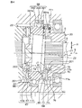
図2は、図1の要部のより具体的な構成を示す断面図である。図2を参照して、ハウジング24は、例えば、アルミニウム合金等の金属を筒状に形成してなるものであり、第1〜第3のハウジング51〜53を含んでいる。このハウジング24内には、第1〜第7の軸受31〜37が収容されている。第1〜第5の軸受31〜35および第7の軸受37は、それぞれ、アンギュラ玉軸受等の転がり軸受であり、第6の軸受36は、針状ころ軸受等の転がり軸受である。
FIG. 2 is a cross-sectional view showing a more specific configuration of the main part of FIG. Referring to FIG. 2, the
第1のハウジング51は筒状をなしており、差動機構としての伝達比可変機構5を収容する差動機構ハウジングを構成しているとともに、伝達比可変機構用モータ23を収容するモータハウジングを構成している。第1のハウジング51の一端は、端壁部材54によって覆われている。第1のハウジング51の一端と端壁部材54とは、ボルト等の締結部材55を用いて互いに固定されている。第1のハウジング51の他端の内周面56に、第2のハウジング52の一端の環状凸部57が嵌合されている。これら第1および第2のハウジング51,52は、ボルト等の締結部材(図示せず)を用いて互いに固定されている。
The
第2のハウジング52は筒状をなしており、トルクセンサ44を収容するセンサハウジングと、モータレゾルバ43を収容するレゾルバハウジングとを構成している。第2のハウジング52の他端の外周面59に、第3のハウジング53の一端の内周面60が嵌合している。
The
第3のハウジング53は、筒状をなしており、減速機構26を収容する減速機構ハウジングを構成している。第3のハウジング53の他端には端壁部61が設けられている。端壁部61は環状をなしており、第3のハウジング53の他端を覆っている。
The
図3は、図2の伝達比可変機構5およびその周辺の拡大図である。図3を参照して、伝達比可変機構5の入力部材20、出力部材22および軌道輪ユニット39の内輪391は、それぞれ、環状をなしている。
FIG. 3 is an enlarged view of the transmission
入力部材20は、第1の歯車として形成されており、入力部材本体201と、入力部材本体201の径方向内方に配置され入力部材本体201と同行回転可能な筒状部材202と、入力部材本体201に保持される複数のピン77と、複数のピン77を入力部材本体201で保持するための内保持器75および外保持器76とを含んでいる。入力部材本体201および筒状部材202は、単一の材料を用いて一体に形成されている。
The
第1のシャフト11の他端は、筒状部材202の挿通孔202aを挿通している。伝達比可変機構5の入力軸としての第1のシャフト11の他端と、筒状部材202とは、例えばセレーション係合によって、トルク伝達可能に連結されている。
The other end of the
出力部材22は、第1の歯車として形成されており、出力部材本体221と、出力部材本体221の径方向内方に配置され出力部材本体221と同行回転可能な筒状部材222と、出力部材本体221に保持される複数のピン87と、複数のピン87を出力部材本体221で保持するための内保持器85および外保持器86とを含んでいる。出力部材本体221および筒状部材222は、単一の材料を用いて一体に形成されている。
The
第2のシャフト12の一端は、出力部材22の筒状部材222の挿通孔222aを挿通している。伝達比可変機構5の出力軸としての第2のシャフト12の中間部と、出力部材22とは、例えばセレーション係合によって、トルク伝達可能に連結されている。
One end of the
軌道輪ユニット39の内輪391は、全体が単一の部材を用いて一体に形成されており、入力部材20と出力部材22との間に配置されている。この内輪391は、第1の歯車としての入力部材20と対をなす第2の歯車として形成されているとともに、第1の歯車としての出力部材22と対をなす第2の歯車として形成されている。内輪391の軸方向に関して、内輪391の第1の端部391aは、第2の歯車の歯車本体として形成されており、第2の端部391bは、第2の歯車の歯車本体として形成されている。第1および第2の端部391a,391bは、互いの軸線が合致しており、この合致する軸線としての第2の軸線Z2の回りを同行回転可能である。
The
上記入力部材20と、入力部材20に動力伝達可能に噛み合う内輪391とによって、第1の歯車装置78が形成されている。また、上記出力部材22と、出力部材22に動力伝達可能に噛み合う内輪391とによって、第2の歯車装置88が形成されている。また、第1の歯車装置78と、第2の歯車装置88とによって、揺動歯車装置84が形成されている。
A
揺動歯車装置84の入力部材20および出力部材22は、それぞれの第1の軸線Z1が合致しており、外輪392の第1の端部391aおよび第2の端部391bを挟んで配置されている。
The
外輪392は、伝達比可変機構用モータ23のロータ231の内周に形成された傾斜孔63に圧入固定されており、ロータ231とは第1の軸線Z1の回りを同行回転する。ロータ231が第1の軸線Z1の回りを回転することに伴い、軌道輪ユニット39がコリオリ運動する。
The
なお、外輪392が入力部材20および出力部材22を差動回転可能に連結するとともに、内輪391が伝達比可変機構用モータ23のロータ231と同行回転可能に連結されるようにしてもよい。この場合、軌道輪ユニット39は、内輪支持型となる。
The
図4は、図3の伝達比可変機構5の要部の拡大図である。図4を参照して、内輪391の第1の端部391aのうち、入力部材20に対向する端面が、第1の端面71とされている。内輪391第2の端部391bのうち、出力部材22に対向する端面が、第2の端面72とされている。
FIG. 4 is an enlarged view of a main part of the transmission
入力部材20および内輪391の第1の端部391aのそれぞれに、第1の凹凸係合部64が設けられている。これにより、入力部材20と第1の端部391aとは動力伝達可能とされている。
A first concavo-convex
また、内輪391の第2の端部391bおよび出力部材22のそれぞれに、第2の凹凸係合部67が設けられている。これにより、第2の端部391bと出力部材22とは動力伝達可能とされている。
Further, a second uneven engagement portion 67 is provided on each of the
図5は、第1の凹凸係合部64の要部の斜視図である。図4および図5を参照して、入力部材本体201の一端面としての動力伝達面70および第1の端部391aの第1の端面71は、ステアリングシャフト3の軸方向S(以下、単に軸方向Sという。)に互いに対向しており、第1の凹凸係合部64は、これら動力伝達面70および第1の端面71を動力伝達可能に係合させる。
FIG. 5 is a perspective view of a main part of the first concave / convex engaging
第1の凹凸係合部64は、動力伝達面70に形成された複数の保持溝79と、各保持溝79に保持された複数のピン77と、内輪391の第1の端部391aの第1の端面71に形成され対応するピン77に係合する複数の歯溝80と、を含んでいる。
The first concavo-convex
入力部材20は、第1および第2の歯車の一方を構成しており、保持溝79およびピン77を含んでいる。内輪391は、第1および第2の歯車の他方を構成しており、歯溝80を含んでいる。
The
なお、本実施の形態では、入力部材20に保持溝79およびピン77を設け、内輪391の第1の端部391aに歯溝80を設ける構成に則して説明するが、これに限らず、内輪391の第1の端部391aに保持溝79およびピン77を設け、入力部材本体201に歯溝80を設けてもよい。このとき、入力部材20は、第1および第2の歯車の他方となり、内輪391は、第1および第2の歯車の一方となる。
In the present embodiment, the
保持溝79、ピン77および歯溝80は、対応する動力伝達面70および第1の端面71において、それぞれの周方向の全域に亘って等間隔に配置されている。
The holding
各ピン77は、入力部材20の歯81を形成するためのものであり、例えば円柱状をなす針状ころである。これらのピン77は、第1の軸線Z1を中心とする放射状に配置されている。各ピン77の半部は、対応する保持溝79から突出して断面半円形形状をなしており、この突出している半部が、入力部材20の歯81とされている。各ピン77のうち、入力部材20の径方向R1に関する外端77aは、環状の外保持器76によって一括して保持されており、入力部材20の径方向R1に関する内端77bは、環状の内保持器75によって一括して保持されている。
Each
各ピン77は、これら外保持器76および内保持器75によって、入力部材本体201に取り付けられている。外保持器76および内保持器75のそれぞれは、弾性を有する部材、例えば合成樹脂により形成されている。
Each
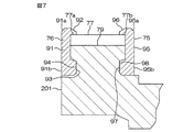
図6は、入力部材20の一部を断面で示す斜視図である。図7は、図6の要部の拡大断面図である。図6および図7を参照して、外保持器76は、環状の本体91を有している。本体91の軸方向の一端91aには、本体91の径方向内方へ突出する環状突起92が形成されており、本体91の軸方向の他端91bには、本体91の径方向内方へ突出する環状の係合突起93が形成されている。
FIG. 6 is a perspective view showing a part of the
環状突起92と入力部材本体201の保持溝79とによって、各ピン77の外端77aが挟持されて保持されている。
The outer ends 77 a of the
係合突起93は、入力部材本体201の外周に形成された環状凹部からなる係合部94に係合されることにより、外保持器76が入力部材本体201に取り付けられている。
The
内保持器75は、環状の本体95を有している。本体95の軸方向の一端95aには、本体95の径方向外方へ突出する環状突起96が形成されており、本体95の軸方向の他端95bには、本体95の径方向外方へ突出する環状の係合突起97が形成されている。
The
環状突起96と入力部材本体201の保持溝79とによって、各ピン77の内端77bが挟持されて保持されている。
The
係合突起97は、入力部材本体201の内周に形成された環状凹部からなる係合部98に係合されることにより、内保持器75が入力部材本体201に取り付けられている。
The
図5を参照して、保持溝79は、第1の軸線Z1を中心に放射状に細長に形成されて、入力部材20の径方向に関して動力伝達面70の全域に延びており、入力部材本体201の周方向に等間隔に配置されている。保持溝79の数は、ピン77の数と等しくされており、各保持溝79にピン77が保持されている。なお、図5では、内保持器75および外保持器76は図示していない。
Referring to FIG. 5, the holding
歯溝80は、第2の軸線Z2を中心に放射状に細長に形成されて、内輪391の径方向に関して第1の端部391aの全域に延びており、第1の端部391aの周方向に等間隔に配置されている。歯溝80の数は、ピン77の数とは同じ数、または異なる数にされている。ピン77の数と歯溝80の数との差に応じて、入力部材本体201と内輪391との間で変速を行うことができる。
The
再び図4を参照して、内輪391の第2の軸線Z2が入力部材20の第1の軸線Z1に対して所定角度σだけ傾斜していることにより、一部の歯81と、一部の歯溝80とが、互いに噛み合っている。
Referring to FIG. 4 again, when the second axis Z2 of the
図8は、図4のVIII−VIII線に沿う要部の断面図である。図8は、歯溝80に噛み合っているピン77(ピン771)の長手方向と直交する断面を示している。図8を参照して説明するときは、ピン771と直交する断面を基準として説明する。
FIG. 8 is a cross-sectional view of a main part taken along line VIII-VIII in FIG. FIG. 8 shows a cross section orthogonal to the longitudinal direction of the pin 77 (pin 771) meshing with the
図8を参照して、本実施の形態の特徴の1つは、保持溝79からピン77が受ける力F1と、歯溝80からピン77が受ける力F2の合力F1+F2が、ピン77を、保持溝79の底79aと歯溝80の底80aのうち、保持溝79の底79a側に付勢するようにしてある点にある。
Referring to FIG. 8, one of the features of the present embodiment is that pin F is held by force F1 that
具体的には、入力部材本体201の保持溝79の内面79bの断面は、いわゆるゴシックアーク形状とされており、底79aが先鋭な形状とされている。内面79bの断面形状は、保持溝79の長手方向の全域に亘って同じ形状を有しており、保持溝79の底79aを挟んで入力部材20の周方向Gに並ぶ一対の第1の部分79c,79dを含んでいる。
Specifically, the cross section of the
一方の第1の部分79cは、相対的に小さい所定の曲率半径U1を有する円弧面である。他方の第1の部分79dは、一方の第1の部分79cとは対称な形状をなしており、一方の第1の部分79cと同じ曲率半径U1を有する円弧面とされている。一方の第1の部分79cの曲率中心79eと他方の第1の部分79dの曲率中心79fとは、周方向Gに関してオフセットされている。
One
また、内輪391の第1の端部391aの歯溝80の内面80bの断面は、いわゆるゴシックアーク形状とされており、底80aが先鋭な形状とされている。内面80bの断面形状は、歯溝80の長手方向の全域に亘って同じ形状を有しており、歯溝80の底80aを挟んで内輪391の周方向に並ぶ一対の第2の部分80c,80dを含んでいる。
Further, the cross section of the inner surface 80b of the
一方の第2の部分80cは、相対的に大きい所定の曲率半径U2を有する円弧面である。他方の第2の部分80dは、一方の第2の部分80cとは対称な形状をなしており、一方の第2の部分80cと同じ曲率半径U2を有する円弧面とされている。一方の第2の部分80cの曲率中心80eと他方の第2の部分80dの曲率中心80fとは、内輪391の周方向に関してオフセットされている。
One
ピン77の外周面77cと、保持溝79の一対の第1の部分79c,79dとは、対応する第1の接触点99c,99d(接触線)でそれぞれ接触している。同様に、ピン77の外周面77cと、歯溝80の一対の第2の部分80c,80dとは、対応する第2の接触点100c,100d(接触線)でそれぞれ接触している。すなわち、ピン77は、保持溝79および歯溝80と4点接触している。
The outer
保持溝79の一方の第1の部分79cと、歯溝80の第2の部分80cとは、ピン77の中心軸線J1を挟んで相対向している。
One
保持溝79の一方の第1の部分79cと、ピン77とは、第1の接触点99cで第1の接触角βをなしている。第1の接触角βとは、ピン77の中心軸線J1および第1の軸線Z1を含む基準平面101と、保持溝79の一方の第1の部分79cからピン77の第1の接触点99cに作用する力としての第1の力F1の作用線とがなす角をいう。
The
また、歯溝80の一方の第2の部分80cと、ピン77とは、第2の接触点100cで第2の接触角αをなしている。第2の接触角αとは、基準平面101と、歯溝80の一方の第2の部分80cからピン77の第2の接触点100cに作用する力としての第2の力F2の作用線とがなす角をいう。
In addition, one
前述したように、保持溝79の一方の第1の部分79cの曲率半径U1が相対的に小さくされ、歯溝80の一方の第2の部分80cの曲率半径U2が相対的に大きくされていることにより、第2の接触角αが相対的に小さく、第1の接触角βが相対的に大きい(α<β)。
As described above, the radius of curvature U1 of the
上記の構成により、入力部材20がその周方向Gの一方G1に回転したとき、第1の力F1のうち、基準平面101に平行な方向Yであって保持溝79から歯溝80に向かう方向Y1の成分F1yは、相対的に小さい。また、第2の力F2のうち、基準平面101に平行な方向Yであって歯溝80から保持溝79に向かう方向Y2の成分F2yは、相対的に大きい。したがって、第1および第2の力F1,F2のうち、基準平面101に平行な上記成分F1y,F2yの和F1y+F2yは、基準平面101に平行な方向Yのうち歯溝80から保持溝79に向かう方向Y2を向き、ピン77を保持溝79の底79a側に付勢するように働く。
With the above configuration, when the
また、保持溝79の他方の第1の部分79dが一方の第1の部分79cとは対称な形状に形成されており、且つ、歯溝80の他方の第2の部分80dが一方の第2の部分80cとは対称な形状に形成されている。これにより、入力部材20がその周方向Gの他方G2に回転したときも、一方G1に回転したときと同様に、ピン77には、保持溝79を保持溝79の底79a側に付勢する力が作用する。
Further, the other
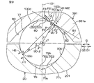
図9は、図8と同じ断面における断面図であり、ピン77に作用するモーメントについて説明するためのものである。図9を参照して、本実施の形態の別の特徴は、ピン77が保持溝79からより確実に抜け出さないようにするために、第1の接触点99c回りに関する第1および第2のモーメントM1,M2のうちの第1のモーメントM1が第2のモーメントM2よりも大きくされている点にある。
FIG. 9 is a cross-sectional view in the same cross section as FIG. 8 and is for explaining the moment acting on the
第1のモーメントM1は、歯溝80の内面80bの一方の第2の部分80cからピン77が受ける第2の力F2がピン77を第1の接触点99c回りの一方H1に回転させるモーメントである。第2のモーメントM2は、歯溝80の内面80bの一方の第1の部分80cに対するピン77の摩擦力F3がピン77を第1の接触点99c回りの他方H2に回転させるモーメントである。
The first moment M1 is a moment that the second force F2 received by the
第1のモーメントM1と比べて第2のモーメントM2が大きくなるようにすることで、これらのモーメントM1,M2の和M1+M2が、第1の接触点99c回りの一方H1に作用する。よって、ピン77が保持溝79の底79a側に付勢され、ピン77が保持溝79からより確実に抜け出さないようにすることができる。
By making the second moment M2 larger than the first moment M1, the sum M1 + M2 of these moments M1 and M2 acts on one H1 around the
第1のモーメントM1を第2のモーメントM2より大きくするために、ピン77と歯溝80の一方の第2の部分80cとの摩擦係数をμとしたときに、下記式(1)が成立している。
In order to make the first moment M1 larger than the second moment M2, when the friction coefficient between the
(β−α)>2×tan−1(μ)・・・・・(1)
上記式(1)が成立することにより、第1のモーメントM1が第2のモーメントM2より大きくなる理由を以下に説明する。
(Β-α)> 2 × tan −1 (μ) (1)
The reason why the first moment M1 becomes larger than the second moment M2 when the above equation (1) is established will be described below.
まず、図9において、第1および第2の接触点99c,100c間を結ぶ線分を線分AB、第1の接触点99cとピン77の中心軸線J1を結ぶ線分を線分AO、第2の接触点100cとピン77の中心軸線J1を結ぶ線分を線分BOとすると、三角形OABは、線分AO=線分BO=ピン77の半径であり、二等辺三角形となる。よって、角度OAB=角度OBA=所定角度θとなる。また、B点(第2の接触点100c)におけるピン77の外周面77cの接線を接線B1とし、B点を通り線分ABに直交する直線を直線B2とすると、直線B1と直線B2とがなす傾斜角は、所定角度θとなる。また、線分BOと、直線B2のうちB点から保持溝79に向かって延びる部分とがなす角度は、(90−θ)°となる。
First, in FIG. 9, a line segment connecting the first and
ここで、入力部材20が周方向Gの一方G1に回転したとき、第2の接触点100cには、歯溝80からの前述した第2の力F2が作用し、また、ピン77と歯溝80との摩擦接触による摩擦力F3が作用する。
Here, when the
摩擦力F3=μ×F2である。摩擦力F3のうち、直線B2方向の成分F3’は、図9から、F3’=F3×cosθ=F2×μ×cosθとなる。よって、線分ABの長さをLとすると、摩擦力F3がピン77を第1の接触点99c回りの他方H2に回転させる第2のモーメントM2は、
F3’×L=F2×μ×cosθ×L・・・・・(2)となる。
Frictional force F3 = μ × F2. Of the frictional force F3, the component F3 ′ in the direction of the straight line B2 is F3 ′ = F3 × cos θ = F2 × μ × cos θ from FIG. Therefore, if the length of the line segment AB is L, the second moment M2 causing the frictional force F3 to rotate the
F3 ′ × L = F2 × μ × cos θ × L (2)
また、第2の力F2のうち、直線B2方向の成分は、図9から、F2’=F2×cos(90−θ)=F2×sinθとなる。よって、第2の力F2がピン77を第1の接触点99c回りの一方H1に回転させる第1のモーメントM1は、
F2’×L=F2×sinθ×L・・・・・(3)となる。
Further, the component of the second force F2 in the direction of the straight line B2 is F2 ′ = F2 × cos (90−θ) = F2 × sin θ from FIG. Therefore, the first moment M1 that causes the second force F2 to rotate the
F2 ′ × L = F2 × sin θ × L (3)
以上より、第2のモーメントM2より第1のモーメントM1が大きいと、すなわち、上記式(2)<上記式(3)となると、ピン77には、当該ピン77を第1の接触点99c回りの一方H2に回転させるモーメントM1+M2が作用することとなり、このモーメントM1+M2によって、ピン77が保持溝79の底79a側に付勢される。
From the above, when the first moment M1 is larger than the second moment M2, that is, when the above equation (2) <the above equation (3) is satisfied, the
上記式(2)<上記式(3)は、すなわち、
F2×μ×cosθ×L<F2×sinθ×Lである。この不等式からF2およびLを除すると、
μcosθ<sinθとなるので、整理すると、
μ<sinθ/cosθとなり、さらには、
μ<tanθ・・・・・(4)となる。
The above formula (2) <the above formula (3) is:
F2 × μ × cos θ × L <F2 × sin θ × L. Dividing F2 and L from this inequality,
Since μcosθ <sinθ,
μ <sin θ / cos θ, and
μ <tan θ (4)
ここで、θは、二等辺三角形OBAで考えると、三角形OBAの内角の和は180°であるので、
180=θ+θ+{α+90+(90−β)}
=2×θ+180+α−βとなる。
Here, when θ is considered as an isosceles triangle OBA, the sum of the inner angles of the triangle OBA is 180 °.
180 = θ + θ + {α + 90 + (90−β)}
= 2 × θ + 180 + α−β.
よって、2×θ=β−αとなり、θ=(β−α)/2となる。 Therefore, 2 × θ = β−α, and θ = (β−α) / 2.
このθを式(4)に代入すると、μ<tan{(β−α)/2}となり、これより、tan−1(μ)<(β−α)/2となる。整理すると、(β−α)>2×tan−1(μ)、すなわち式(1)となる。 Substituting this θ into equation (4) results in μ <tan {(β−α) / 2}, and thus tan −1 (μ) <(β−α) / 2. To summarize, (β−α)> 2 × tan −1 (μ), that is, Equation (1).
したがって、第1の接触点99c回りのモーメントによってピン77を保持溝79の底79a側に付勢するには、第1の接触角βと第2の接触角αとの角度差(β−α)は、2×tan−1(μ)より大きければよいことになる。
Therefore, in order to urge the
例えば、摩擦係数μが0.1のとき、角度差(β−α)は、2×tan−1(0.1)≒11.42°より大きければよい。以上より、第1の接触角βと第2の接触角αとは、例えば、図10に示すグラフの関係を満たすように設定できる。 For example, when the friction coefficient μ is 0.1, the angle difference (β−α) may be larger than 2 × tan −1 (0.1) ≈11.42 °. From the above, the first contact angle β and the second contact angle α can be set to satisfy the relationship of the graph shown in FIG. 10, for example.
第1の接触角βは、大きいほど好ましいが、保持溝79の加工上の制限により、例えば約81°±2°に設定される。また、第2の接触角αは、ピン77の抜け防止の観点から、例えば約66.5°±2°に設定される。上記の±2°は、寸法公差である。
The first contact angle β is preferably as large as possible, but is set to about 81 ° ± 2 °, for example, due to processing limitations of the holding
また、保持溝79の他方の第1の部分79dが一方の第1の部分79cとは対称な形状に形成されており、且つ、歯溝80の他方の第2の部分80dが一方の第2の部分80cとは対称な形状に形成されている。これにより、入力部材20がその周方向Gの他方G2に回転したときも、一方G1に回転したときと同様に、ピン77には、ピン77を保持溝79の底79a側に付勢するモーメントが生じる。
Further, the other
図4を参照して、出力部材本体221の一端面としての動力伝達面73および内輪391の第2の端面72は、軸方向Sに互いに対向しており、第2の凹凸係合部67は、これら動力伝達面73および第2の端面72を動力伝達可能に係合させる。
Referring to FIG. 4, the power transmission surface 73 as one end surface of the output member
第2の凹凸係合部67は、動力伝達面73に形成された複数の保持溝109と、各保持溝109に保持された複数のピン87と、内輪391の第2の端部391bの第2の端面72に形成され対応するピン87に係合する複数の歯溝110と、を含んでいる。
The second concavo-convex engaging portion 67 includes a plurality of holding grooves 109 formed on the power transmission surface 73, a plurality of
出力部材22は、第1および第2の歯車の一方を構成しており、保持溝109およびピン87を含んでいる。内輪391は、第1および第2の歯車の他方を構成しており、歯溝110を含んでいる。
The
なお、本実施の形態では、出力部材22に保持溝109およびピン87を設け、内輪391の第2の端部391bに歯溝110を設ける構成に則して説明するが、これに限らず、内輪391の第2の端部391bに保持溝109およびピン87を設け、出力部材本体221に歯溝110を設けてもよい。このとき、出力部材22は、第1および第2の歯車の他方となり、内輪391は、第1および第2の歯車の一方となる。
In the present embodiment, the
第2の凹凸係合部67の保持溝109およびピン87は、第1の凹凸係合部64の保持溝79およびピン77と同様の構成を有しており、第2の凹凸係合部67の歯溝110は、第1の凹凸係合部64の歯溝80と同様の構成を有している。したがって、第2の凹凸係合部67の詳細についての説明は省略する。また、第2の凹凸係合部67のピン87を保持するための内保持器85および外保持器86が設けられている。これらの保持器85,86は、対応する内保持器75および外保持器76と同様の構成を有しているため、詳細な説明は省略する。
The holding groove 109 and the
図3を参照して、伝達比可変機構用モータ23のロータ231は、軸方向Sに延びる筒状のロータコア112と、ロータコア112の外周面に固定された永久磁石113とを含んでいる。
Referring to FIG. 3, the
本実施の形態では、軌道輪ユニット39の外輪392を支持するロータコア112が、第1の軸受31を介して入力部材20の筒状部材202を回転可能に支持するとともに、第3の軸受33を介して出力部材22の筒状部材222を回転可能に支持している。
In the present embodiment, the
また、ロータコア112は、上記第1および第3の軸受31,33を軸方向Sに挟む第2および第4の軸受32,34によって、両持ち支持されている。
The
第2の軸受32は、第1のハウジング51の一端の内径部に形成された環状凸部114に保持されている。第4の軸受34は、第2のハウジング52の他端の内径部に形成された環状の延伸部115に保持されている。
The
環状の延伸部115は、第2のハウジング52の他端に設けられた隔壁部116から、軸方向Sの一方S1側に延びる筒状をなしており、ロータコア112を挿通している。
The annular extending
伝達比可変機構用モータ23のステータ232は、第1のハウジング51の内周面に焼きばめ等によって固定されており、ロータ231の永久磁石113を取り囲んでいる。
The
モータレゾルバ43は、レゾルバロータ117とレゾルバステータ118とを含んでいる。レゾルバロータ117は、ロータコア112の他端の外周面に固定されている。レゾルバステータ118は、第2のハウジング52の内周面に固定されている。
The
トルクセンサ44は、伝達比可変機構用モータ23のロータコア112の径方向内方に配置されている。
The
図2を参照して、トルクセンサ44に対して軸方向Sの他方S2側に第5の軸受35が配置されている。第5の軸受35は、第2のハウジング52の隔壁部116に保持されているとともに、第3のシャフト13の一端を回転可能に支持している。
Referring to FIG. 2, a
第2のシャフト12と第3のシャフト13とは、第6の軸受36を介して相対回転可能に互いに支持されている。
The
第3のシャフト13の中間部と第3のハウジング53の端壁部61との間に第7の軸受37が介在している。端壁部61は、第7の軸受37を介して第3のシャフト13を回転可能に支持している。
A
以上の次第で、本実施の形態によれば、第1の歯車装置78において、保持溝79および歯溝80からピン77が受ける力の合力F1+F2が、ピン77を保持溝79の底79a側に付勢するようにしてある。これにより、ピン77を保持溝79から外れないように付勢することができる。したがって、歯81を構成するピン77の浮き上がりや抜けを防止できる。その結果、第1の歯車装置78におけるトルクの抜けや異音の発生を抑制できる。
As described above, according to the present embodiment, in the
第2の歯車装置88においても、第1の歯車装置78における作用と同様の作用により、歯111を構成するピン87の出力部材本体221からの浮き上がりや抜けをより確実に防止できる。その結果、第2の歯車装置88におけるトルクの抜けや異音の発生を抑制できる。
Also in the
また、第1の歯車装置78において、保持溝79に対するピン77の第1の接触角βは、歯溝80に対するピンの第2の接触角αよりも大きくされている。これにより、保持溝79からピン77に作用する力F1のうち、保持溝79から歯溝80に向かう方向Y1の成分F1yを相対的に低くできるとともに、歯溝80からピン77に作用する力F2のうち、歯溝80から保持溝79に向かう方向Y2の成分F2yを相対的に高くできる。これにより、上記2つの成分F1y,F2yの和F1y+F2yは、歯溝80から保持溝79に向かう方向Y2を向くものとなり、ピン77を入力部材本体201の保持溝79側に確実に付勢することができる。
Further, in the
第2の歯車装置88においても、第1の歯車装置78における作用と同様の作用により、ピン87を出力部材本体221の保持溝109側に確実に付勢することができる。
Also in the
さらに、第1の歯車装置78において、第1のモーメントM1は、ピン77に関する第2のモーメントM2よりも大きくされている。
Further, in the
第1のモーメントM1は、ピン77を保持溝79の底79a側に向けて付勢するモーメントであり、第2のモーメントM2は、ピン77を保持溝79から抜けさせるように働くモーメントである。この第1のモーメントM1が第2のモーメントM2よりも大きくされていることにより、第1および第2のモーメントM1,M2の和M1+M2は、ピン77を保持溝79の底79a側に向けて付勢するモーメントとなり、ピン77を入力部材本体201の保持溝79から抜けることをより確実に防止できる。
The first moment M1 is a moment that urges the
第2の歯車装置88においても、第1の歯車装置78における作用と同様の作用により、ピン87を出力部材本体221の保持溝109から抜けることをより確実に防止できる。
Also in the
また、第1の歯車装置78において、内保持器75および外保持器76がピン77から受ける力が小さくて済むので、これら内保持器75および外保持器76に必要な強度が小さくて済み、内保持器75および外保持器76の小型化を通じて第1の歯車装置78を小型化できる。
Further, in the
第2の歯車装置88においても、第1の歯車装置78における作用と同様の作用効果により、内保持器85および外保持器86の小型化を通じて第2の歯車装置88を小型化できる。
Also in the
本発明は、以上の実施の形態の内容に限定されるものではなく、請求項記載の範囲内において種々の変更が可能である。 The present invention is not limited to the contents of the above-described embodiment, and various modifications can be made within the scope of the claims.
例えば、図11に示すように、円錐台形状のピン77Aと、このピン77Aの形状に合致する形状の、保持溝79Aおよび歯溝80Aとを用いてもよい。ピン77Aは、入力部材本体201の径方向内方に進むにしたがい、直径が小さくなっている。
For example, as shown in FIG. 11, a truncated cone-shaped
また、第1および第2の歯車装置78,88のうちの何れか一方においてのみ、第1の接触角βが第2の接触角αより大きくされていてもよい。
Further, only in any one of the first and
さらに、各上記実施の形態では、操舵補助用モータ25をステアリングコラムに配置するコラム式電動パワーステアリング装置に適用した例を説明したが、これに限定されない。例えば、操舵補助用モータ25をステアリングラックハウジングに設けるラックアシスト式電動パワーステアリング装置に本発明を適用してもよい。また、操舵補助用モータ25をピニオン軸15に配置するピニオンアシスト式電動パワーステアリング装置に本発明を適用してもよい。
Further, in each of the above-described embodiments, the example in which the steering assist
さらに、上記各実施の形態では、伝達比可変機構5をステアリングシャフト3に配置した例を説明したが、伝達比可変機構5を中間軸8またはピニオン軸15に配置してもよい。
Further, in each of the above embodiments, the example in which the transmission
また、本発明の伝達比可変機構を、車両用操舵装置以外の他の装置に適用することができる。例えば、車両の車輪のトー角を可変可能なトー角可変機構や、車両の車輪のキャンバー角を可変可能なキャンバー角可変機構や、車両のショックアブソーバの減衰力を可変可能な減衰力可変機構等に、本発明の伝達比可変機構を用いることができる。 Further, the transmission ratio variable mechanism of the present invention can be applied to devices other than the vehicle steering device. For example, a toe angle variable mechanism that can change the toe angle of a vehicle wheel, a camber angle variable mechanism that can change a camber angle of a vehicle wheel, a damping force variable mechanism that can change the damping force of a vehicle shock absorber, etc. In addition, the transmission ratio variable mechanism of the present invention can be used.
さらに、本発明は、一対の歯車としての第1および第2の歯車を有する他の歯車装置に適用することができ、また、車両用操舵装置以外の他の一般の装置に備えられる歯車装置に適用することができる。 Furthermore, the present invention can be applied to another gear device having the first and second gears as a pair of gears, and to a gear device provided in another general device other than the vehicle steering device. Can be applied.
20…入力部材(第1の歯車)、22…出力部材(第1の歯車)、39…内輪(第2の歯車)、77,77A…ピン、78…第1の歯車装置(歯車装置)、79,79A…保持溝、79b…(保持溝の)内面、80,80A…歯溝、80b…(歯溝の)内面、81…歯、84…揺動歯車装置、87…ピン、88…第2の歯車装置(歯車装置)、99c,99d…第1の接触点(保持溝およびピンの接触点)、109…保持溝、110…歯溝、111…歯、F1…保持溝からピンが受ける力、F2…歯溝からピンが受ける力、F3…歯溝の内面に対するピンの摩擦力、M1…第1のモーメント、M2…第2のモーメント、Z1…第1の軸線、Z2…第2の軸線、α…第2の接触角、β…第1の接触角。
DESCRIPTION OF
Claims (2)
第1の軸線に対して傾斜する第2の軸線の回りに回転可能とされ第1の歯車と動力伝達可能に噛み合う第2の歯車とを備え、
上記第1および第2の歯車の一方は、当該一方の歯車の軸線を中心に放射状に配置された複数の保持溝と、各保持溝に保持され上記第1および第2の歯車の上記一方の歯をそれぞれ構成する複数のピンとを含み、
上記第1および第2の歯車の他方は、当該他方の歯車の軸線を中心に放射状に配置され上記ピンに係合可能な複数の歯溝を有し、
保持溝および歯溝からピンが受ける力の合力が、ピンを保持溝側に付勢するようにしてあり、
上記ピンの中心軸線および上記第1の軸線を含む基準平面と、上記保持溝の内面から上記ピンと上記保持溝の内面との接触点に作用する力の作用線とがなす角である第1の接触角βは、上記基準平面と、歯溝の内面から上記ピンと上記歯溝の内面との接触点に作用する力の作用線とがなす角である第2の接触角αよりも大きく、
上記ピンと上記歯溝との摩擦係数をμとしたときに(β−α)>2×tan-1(μ)が成立するように上記接触角βおよびαのそれぞれを設定することにより、上記歯溝からピンが受ける力がピンを保持溝およびピンの接触点回りに回転させる第1のモーメントは、歯溝の内面に対するピンの摩擦力がピンを上記保持溝およびピンの接触点回りに回転させる第2のモーメントよりも大きくされていることを特徴とする歯車装置。 A first gear rotatable about a first axis;
A second gear that is rotatable about a second axis that is inclined with respect to the first axis and that meshes with the first gear so as to be capable of transmitting power;
One of the first and second gears includes a plurality of holding grooves arranged radially about the axis of the one gear, and the one of the first and second gears held in each holding groove. A plurality of pins each constituting a tooth,
The other of the first and second gears has a plurality of tooth grooves that are radially arranged around the axis of the other gear and are engageable with the pin,
The resultant force received by the pin from the holding groove and tooth groove urges the pin toward the holding groove,
A reference plane including the central axis and said first axis of said pin, first is angle between the line of action of the force acting on the point of contact with the inner surface of the pin and the retaining groove from the inner surface of the holding groove the contact angle beta, and the reference plane, larger than α the second contact angle is angle between the line of action of the force acting on the point of contact from the inner surface and the inner surface of the pin and the tooth grooves of the tooth ,
By setting each of the contact angles β and α such that (β−α)> 2 × tan −1 (μ) is established when the friction coefficient between the pin and the tooth gap is μ, the teeth The first moment that the force received by the pin from the groove rotates the pin around the contact point between the holding groove and the pin, the frictional force of the pin against the inner surface of the tooth groove causes the pin to rotate around the contact point between the holding groove and the pin . A gear device characterized in that it is larger than the second moment.
2つの第1の歯車は、2つの第2の歯車を挟んで配置されており、
上記2つの第2の歯車は、互いの軸線が合致するように配置され第2の軸線の回りに同行回転可能に連結されていることを特徴とする揺動歯車装置。 Two gear devices according to claim 1 are provided,
The two first gears are arranged with the two second gears in between,
The oscillating gear device, wherein the two second gears are arranged so that their axes coincide with each other, and are connected so as to be able to rotate around the second axis.
Priority Applications (5)
| Application Number | Priority Date | Filing Date | Title |
|---|---|---|---|
| JP2009004859A JP5433238B2 (en) | 2009-01-13 | 2009-01-13 | Gear device and swing gear device |
| CN200910254282.7A CN101776130B (en) | 2009-01-13 | 2009-12-14 | Gear set and nutation gear set |
| US12/652,880 US8216104B2 (en) | 2009-01-13 | 2010-01-06 | Gear set and nutation gear set |
| EP10150538A EP2206936B1 (en) | 2009-01-13 | 2010-01-12 | Gear set and nutation gear set |
| AT10150538T ATE526524T1 (en) | 2009-01-13 | 2010-01-12 | GEAR SET AND NUTATION GEAR SET |
Applications Claiming Priority (1)
| Application Number | Priority Date | Filing Date | Title |
|---|---|---|---|
| JP2009004859A JP5433238B2 (en) | 2009-01-13 | 2009-01-13 | Gear device and swing gear device |
Publications (3)
| Publication Number | Publication Date |
|---|---|
| JP2010164088A JP2010164088A (en) | 2010-07-29 |
| JP2010164088A5 JP2010164088A5 (en) | 2012-01-26 |
| JP5433238B2 true JP5433238B2 (en) | 2014-03-05 |
Family
ID=41719310
Family Applications (1)
| Application Number | Title | Priority Date | Filing Date |
|---|---|---|---|
| JP2009004859A Active JP5433238B2 (en) | 2009-01-13 | 2009-01-13 | Gear device and swing gear device |
Country Status (5)
| Country | Link |
|---|---|
| US (1) | US8216104B2 (en) |
| EP (1) | EP2206936B1 (en) |
| JP (1) | JP5433238B2 (en) |
| CN (1) | CN101776130B (en) |
| AT (1) | ATE526524T1 (en) |
Families Citing this family (11)
| Publication number | Priority date | Publication date | Assignee | Title |
|---|---|---|---|---|
| JP5282938B2 (en) * | 2008-07-07 | 2013-09-04 | 株式会社ジェイテクト | Transmission ratio variable mechanism and vehicle steering apparatus including the same |
| US20110017005A1 (en) * | 2009-07-22 | 2011-01-27 | International Truck Intellectual Property Company, Llc | Reduced friction ring and pinion gear set |
| JP5423461B2 (en) * | 2010-02-12 | 2014-02-19 | 株式会社ジェイテクト | Machining method of oscillating gear |
| JP2014035016A (en) * | 2012-08-08 | 2014-02-24 | Jtekt Corp | Transmission ratio variable device |
| JP2014098469A (en) * | 2012-11-16 | 2014-05-29 | Jtekt Corp | Transmission ratio variable device |
| JP6305076B2 (en) * | 2014-01-29 | 2018-04-04 | キヤノン株式会社 | Gear mechanism, transmission, and articulated robot arm |
| CN107250607B (en) * | 2015-03-02 | 2020-08-21 | Thk株式会社 | Speed reducing or increasing device |
| JP6954817B2 (en) * | 2017-11-30 | 2021-10-27 | ナブテスコ株式会社 | Auxiliary device |
| US11105397B2 (en) | 2018-05-15 | 2021-08-31 | Robotis Co., Ltd. | Gear module comprising two-point contact internal gear |
| CN108533708B (en) * | 2018-06-15 | 2022-08-09 | 王踊 | Thrust hobbing gear and transmission device using same |
| CN111237400B (en) * | 2020-03-20 | 2023-01-17 | 苏州大学 | Double-spherical surface cycloid roller nutation transmission device |
Family Cites Families (10)
| Publication number | Priority date | Publication date | Assignee | Title |
|---|---|---|---|---|
| IS988B6 (en) * | 1975-04-15 | 1978-03-08 | Balcke-Dürr AG. | Gear system |
| CN1018567B (en) * | 1988-06-30 | 1992-10-07 | 湖南省机械研究所 | Mixed few-differential spider reducer and speed variator |
| EP0412767A3 (en) * | 1989-08-08 | 1992-11-19 | Tai-Her Yang | A rigid harmonic speed reduction or angle cutting driving method and structure |
| JPH0544794A (en) * | 1991-08-08 | 1993-02-23 | Hitachi Ltd | Reduction gear with rocking rotary plate |
| IT235746Y1 (en) | 1995-12-21 | 2000-07-12 | Galasso Piero | EQUIPMENT FOR DETECTION AND VISUALIZATION OF PLANTAR PRESSURES IN THE STATE OF QUIET AND MOTORCYCLE |
| US5967883A (en) * | 1996-12-28 | 1999-10-19 | Namu Co., Ltd. | Working apparatus provided with rotary table for mass-production of gears |
| JPH10246293A (en) * | 1997-03-04 | 1998-09-14 | Namu:Kk | Speed change gear device |
| JPH11315908A (en) * | 1998-05-06 | 1999-11-16 | Namu:Kk | Gear pair and coriolis motion gear device |
| US6348021B1 (en) * | 1999-12-15 | 2002-02-19 | Alphonse J. Lemanski | Variable speed power transmission |
| JP4939191B2 (en) * | 2006-12-01 | 2012-05-23 | 荻野工業株式会社 | Oscillating gear unit |
-
2009
- 2009-01-13 JP JP2009004859A patent/JP5433238B2/en active Active
- 2009-12-14 CN CN200910254282.7A patent/CN101776130B/en active Active
-
2010
- 2010-01-06 US US12/652,880 patent/US8216104B2/en active Active
- 2010-01-12 EP EP10150538A patent/EP2206936B1/en active Active
- 2010-01-12 AT AT10150538T patent/ATE526524T1/en not_active IP Right Cessation
Also Published As
| Publication number | Publication date |
|---|---|
| EP2206936A1 (en) | 2010-07-14 |
| ATE526524T1 (en) | 2011-10-15 |
| EP2206936B1 (en) | 2011-09-28 |
| CN101776130A (en) | 2010-07-14 |
| CN101776130B (en) | 2014-09-03 |
| US8216104B2 (en) | 2012-07-10 |
| US20100179012A1 (en) | 2010-07-15 |
| JP2010164088A (en) | 2010-07-29 |
Similar Documents
| Publication | Publication Date | Title |
|---|---|---|
| JP5433238B2 (en) | Gear device and swing gear device | |
| JP5227853B2 (en) | Oscillating gear device, transmission ratio variable mechanism, and vehicle steering device | |
| JP5282938B2 (en) | Transmission ratio variable mechanism and vehicle steering apparatus including the same | |
| JP5234314B2 (en) | Vehicle steering system | |
| EP2202131B1 (en) | Transmission ratio variable mechanism and steering device for vehicle equipped with it | |
| JP5229543B2 (en) | Vehicle steering system | |
| JP5218830B2 (en) | Vehicle steering system | |
| JP5224109B2 (en) | Vehicle steering system | |
| WO2020009074A1 (en) | Steering wheel counterforce application device | |
| JP5257682B2 (en) | Oscillating gear device, transmission ratio variable mechanism, and vehicle steering device | |
| JP5472686B2 (en) | Vehicle steering system | |
| JP5234313B2 (en) | Vehicle steering system | |
| JP2010052508A (en) | Vehicular steering device | |
| JP5110362B2 (en) | Transmission ratio variable mechanism and vehicle steering apparatus including the same | |
| JP5110361B2 (en) | Transmission ratio variable mechanism and vehicle steering apparatus including the same | |
| JP7191830B2 (en) | Spline structure, reducer or speed increaser, constant velocity joint | |
| JP5333846B2 (en) | Oscillating gear device, transmission ratio variable mechanism, and vehicle steering device | |
| JP2010060018A (en) | Oscillating gear device, transmission ratio variable mechanism, and vehicular steering device | |
| JP5158419B2 (en) | Vehicle steering system | |
| JP2009208557A (en) | Vehicular steering device | |
| JP2010036748A (en) | Reduction gear, and electric power steering device having the same | |
| JP2005231581A (en) | Electric power steering device | |
| JP2010006341A (en) | Steering device for vehicle | |
| JP2009143317A (en) | Electrical power steering device |
Legal Events
| Date | Code | Title | Description |
|---|---|---|---|
| A711 | Notification of change in applicant |
Free format text: JAPANESE INTERMEDIATE CODE: A711 Effective date: 20110525 |
|
| A521 | Request for written amendment filed |
Free format text: JAPANESE INTERMEDIATE CODE: A821 Effective date: 20110525 |
|
| A521 | Request for written amendment filed |
Free format text: JAPANESE INTERMEDIATE CODE: A523 Effective date: 20110719 |
|
| A521 | Request for written amendment filed |
Free format text: JAPANESE INTERMEDIATE CODE: A821 Effective date: 20110720 |
|
| A521 | Request for written amendment filed |
Free format text: JAPANESE INTERMEDIATE CODE: A523 Effective date: 20111207 |
|
| A621 | Written request for application examination |
Free format text: JAPANESE INTERMEDIATE CODE: A621 Effective date: 20111207 |
|
| A977 | Report on retrieval |
Free format text: JAPANESE INTERMEDIATE CODE: A971007 Effective date: 20121211 |
|
| A131 | Notification of reasons for refusal |
Free format text: JAPANESE INTERMEDIATE CODE: A131 Effective date: 20121220 |
|
| A02 | Decision of refusal |
Free format text: JAPANESE INTERMEDIATE CODE: A02 Effective date: 20130411 |
|
| A521 | Request for written amendment filed |
Free format text: JAPANESE INTERMEDIATE CODE: A523 Effective date: 20130710 |
|
| A521 | Request for written amendment filed |
Free format text: JAPANESE INTERMEDIATE CODE: A821 Effective date: 20130711 |
|
| A911 | Transfer to examiner for re-examination before appeal (zenchi) |
Free format text: JAPANESE INTERMEDIATE CODE: A911 Effective date: 20130805 |
|
| A131 | Notification of reasons for refusal |
Free format text: JAPANESE INTERMEDIATE CODE: A131 Effective date: 20131010 |
|
| A521 | Request for written amendment filed |
Free format text: JAPANESE INTERMEDIATE CODE: A523 Effective date: 20131018 |
|
| TRDD | Decision of grant or rejection written | ||
| A01 | Written decision to grant a patent or to grant a registration (utility model) |
Free format text: JAPANESE INTERMEDIATE CODE: A01 Effective date: 20131114 |
|
| A61 | First payment of annual fees (during grant procedure) |
Free format text: JAPANESE INTERMEDIATE CODE: A61 Effective date: 20131209 |
|
| R150 | Certificate of patent or registration of utility model |
Free format text: JAPANESE INTERMEDIATE CODE: R150 Ref document number: 5433238 Country of ref document: JP Free format text: JAPANESE INTERMEDIATE CODE: R150 |
|
| S111 | Request for change of ownership or part of ownership |
Free format text: JAPANESE INTERMEDIATE CODE: R313117 |
|
| R371 | Transfer withdrawn |
Free format text: JAPANESE INTERMEDIATE CODE: R371 |
|
| S111 | Request for change of ownership or part of ownership |
Free format text: JAPANESE INTERMEDIATE CODE: R313117 |
|
| S531 | Written request for registration of change of domicile |
Free format text: JAPANESE INTERMEDIATE CODE: R313531 |
|
| R350 | Written notification of registration of transfer |
Free format text: JAPANESE INTERMEDIATE CODE: R350 |
|
| R250 | Receipt of annual fees |
Free format text: JAPANESE INTERMEDIATE CODE: R250 |
|
| R250 | Receipt of annual fees |
Free format text: JAPANESE INTERMEDIATE CODE: R250 |
|
| R250 | Receipt of annual fees |
Free format text: JAPANESE INTERMEDIATE CODE: R250 |