JP5430409B2 - Surgical device and method of use thereof - Google Patents
Surgical device and method of use thereof Download PDFInfo
- Publication number
- JP5430409B2 JP5430409B2 JP2009554767A JP2009554767A JP5430409B2 JP 5430409 B2 JP5430409 B2 JP 5430409B2 JP 2009554767 A JP2009554767 A JP 2009554767A JP 2009554767 A JP2009554767 A JP 2009554767A JP 5430409 B2 JP5430409 B2 JP 5430409B2
- Authority
- JP
- Japan
- Prior art keywords
- fluid
- electrodes
- electrode
- tissue
- distal end
- Prior art date
- Legal status (The legal status is an assumption and is not a legal conclusion. Google has not performed a legal analysis and makes no representation as to the accuracy of the status listed.)
- Expired - Fee Related
Links
Images


Classifications
-
- A—HUMAN NECESSITIES
- A61—MEDICAL OR VETERINARY SCIENCE; HYGIENE
- A61B—DIAGNOSIS; SURGERY; IDENTIFICATION
- A61B18/00—Surgical instruments, devices or methods for transferring non-mechanical forms of energy to or from the body
- A61B18/04—Surgical instruments, devices or methods for transferring non-mechanical forms of energy to or from the body by heating
- A61B18/12—Surgical instruments, devices or methods for transferring non-mechanical forms of energy to or from the body by heating by passing a current through the tissue to be heated, e.g. high-frequency current
- A61B18/14—Probes or electrodes therefor
- A61B18/148—Probes or electrodes therefor having a short, rigid shaft for accessing the inner body transcutaneously, e.g. for neurosurgery or arthroscopy
-
- A—HUMAN NECESSITIES
- A61—MEDICAL OR VETERINARY SCIENCE; HYGIENE
- A61B—DIAGNOSIS; SURGERY; IDENTIFICATION
- A61B18/00—Surgical instruments, devices or methods for transferring non-mechanical forms of energy to or from the body
- A61B18/04—Surgical instruments, devices or methods for transferring non-mechanical forms of energy to or from the body by heating
- A61B18/12—Surgical instruments, devices or methods for transferring non-mechanical forms of energy to or from the body by heating by passing a current through the tissue to be heated, e.g. high-frequency current
- A61B18/14—Probes or electrodes therefor
- A61B18/1402—Probes for open surgery
-
- A—HUMAN NECESSITIES
- A61—MEDICAL OR VETERINARY SCIENCE; HYGIENE
- A61B—DIAGNOSIS; SURGERY; IDENTIFICATION
- A61B18/00—Surgical instruments, devices or methods for transferring non-mechanical forms of energy to or from the body
- A61B2018/00053—Mechanical features of the instrument of device
- A61B2018/00059—Material properties
- A61B2018/00071—Electrical conductivity
- A61B2018/00083—Electrical conductivity low, i.e. electrically insulating
-
- A—HUMAN NECESSITIES
- A61—MEDICAL OR VETERINARY SCIENCE; HYGIENE
- A61B—DIAGNOSIS; SURGERY; IDENTIFICATION
- A61B18/00—Surgical instruments, devices or methods for transferring non-mechanical forms of energy to or from the body
- A61B2018/00315—Surgical instruments, devices or methods for transferring non-mechanical forms of energy to or from the body for treatment of particular body parts
- A61B2018/00434—Neural system
- A61B2018/0044—Spinal cord
-
- A—HUMAN NECESSITIES
- A61—MEDICAL OR VETERINARY SCIENCE; HYGIENE
- A61B—DIAGNOSIS; SURGERY; IDENTIFICATION
- A61B18/00—Surgical instruments, devices or methods for transferring non-mechanical forms of energy to or from the body
- A61B2018/00571—Surgical instruments, devices or methods for transferring non-mechanical forms of energy to or from the body for achieving a particular surgical effect
- A61B2018/00619—Welding
-
- A—HUMAN NECESSITIES
- A61—MEDICAL OR VETERINARY SCIENCE; HYGIENE
- A61B—DIAGNOSIS; SURGERY; IDENTIFICATION
- A61B18/00—Surgical instruments, devices or methods for transferring non-mechanical forms of energy to or from the body
- A61B2018/00636—Sensing and controlling the application of energy
- A61B2018/00696—Controlled or regulated parameters
- A61B2018/00702—Power or energy
-
- A—HUMAN NECESSITIES
- A61—MEDICAL OR VETERINARY SCIENCE; HYGIENE
- A61B—DIAGNOSIS; SURGERY; IDENTIFICATION
- A61B18/00—Surgical instruments, devices or methods for transferring non-mechanical forms of energy to or from the body
- A61B2018/00636—Sensing and controlling the application of energy
- A61B2018/00773—Sensed parameters
- A61B2018/00875—Resistance or impedance
-
- A—HUMAN NECESSITIES
- A61—MEDICAL OR VETERINARY SCIENCE; HYGIENE
- A61B—DIAGNOSIS; SURGERY; IDENTIFICATION
- A61B2218/00—Details of surgical instruments, devices or methods for transferring non-mechanical forms of energy to or from the body
- A61B2218/001—Details of surgical instruments, devices or methods for transferring non-mechanical forms of energy to or from the body having means for irrigation and/or aspiration of substances to and/or from the surgical site
- A61B2218/002—Irrigation
Description
本発明は、手術中、特に開口手術および腹腔鏡手術のような最小侵襲手術中に、人体の組織上で使用するための手術用デバイス、システムおよび方法に関する。 The present invention relates to surgical devices, systems and methods for use on human tissue during surgery, particularly during minimally invasive surgery such as open surgery and laparoscopic surgery.
本発明は、2007年3月23日付けで出願された米国仮出願第60/896,768号の出願日の利益を主張する(その内容は、この引用によって本明細書に組み込まれる)。 The present invention claims the benefit of the filing date of US Provisional Application No. 60 / 896,768, filed March 23, 2007, the contents of which are incorporated herein by this reference.
Bovieペンシルなどのドライチップ電気外科デバイスは、治療されている組織の温度を100℃よりも著しく高い温度まで上昇させることがあり、これは、組織の乾燥、電極への組織の固着、組織の穴あき、焦げの形成および発煙を生じる。 Dry tip electrosurgical devices, such as Bovie pencils, can raise the temperature of the tissue being treated to temperatures significantly above 100 ° C., which can lead to tissue drying, tissue fixation to electrodes, tissue holes. Causes burning, burning, and fuming.
さらに、ある手術デバイスは、限られた手術スペースで使用するには大き過ぎ、かつ/または、組織を治療する際に血液の損失を抑える機能を全く持たない。 Further, some surgical devices are too large for use in limited surgical spaces and / or have no function to reduce blood loss when treating tissue.
最近、流体支援電気外科デバイスが開発されたが、これは、組織の治療中、組織の乾燥、電極固着、発煙および焦げの形成といった望ましくない結果を防止するために、食塩水を使用する。だが、過度に大量の食塩水は過度の電気的拡散および電極‐組織インターフェースにおける冷却を生じる。これによって、治療されている組織の温度が低下し、そして、組織の治療のための所望の組織温度を実現するために、より長い治療時間が必要になる。長い治療時間は手術に関しては好ましくない。というのは、可能な限り素早く手術処置を実施することが、患者、外科医および病院にとって最も重要なことだからである。 Recently, fluid-assisted electrosurgical devices have been developed that use saline to prevent undesirable effects such as tissue drying, electrode sticking, fuming and scorching during tissue treatment. However, an excessive amount of saline results in excessive electrical diffusion and cooling at the electrode-tissue interface. This reduces the temperature of the tissue being treated and requires a longer treatment time to achieve the desired tissue temperature for treatment of the tissue. Long treatment times are undesirable for surgery. This is because it is most important for patients, surgeons and hospitals to perform surgical procedures as quickly as possible.
こうした点に鑑みて上述した問題を解決できるデバイスおよび方法が求められていた。 In view of these points, devices and methods that can solve the above-described problems have been demanded.
本発明は、ある実施形態においては、組織を治療するために電気外科ハンドヘルドデバイスへの高周波パワーおよび流体の制御された供給を実現するための電気外科装置を提供する。当該装置は、高周波パワーを供給するための高周波発生器(高周波発生器からの高周波パワーは高周波パワーレベルを選択可能である)と、流体を供給するためのポンプと、ハンドデバイスに流体を充填するためのプライマーと、高周波パワーレベルと流体の流量との間の関数的関係に従いポンプによって供給される流体の流量を制御するためのコントロールシステム(この関数的関係は、高周波パワーレベルの増大に応じて流体の流量を増大させ、かつ、高周波パワーレベルの低減に応じて流体の流量を低減させる)と、高周波パワーレベルと流体の流量との間の関数的関係を変化させる流体流量セレクターとを具備してなる。 The present invention, in one embodiment, provides an electrosurgical apparatus for providing a controlled supply of radio frequency power and fluid to an electrosurgical handheld device to treat tissue. The apparatus includes a high-frequency generator for supplying high-frequency power (the high-frequency power from the high-frequency generator can select a high-frequency power level), a pump for supplying fluid, and filling the hand device with fluid. And a control system for controlling the flow rate of the fluid supplied by the pump according to the functional relationship between the high frequency power level and the fluid flow rate (this functional relationship depends on the increase of the high frequency power level) A fluid flow selector that increases the fluid flow rate and reduces the fluid flow rate in response to a reduction in the high frequency power level) and a functional relationship between the high frequency power level and the fluid flow rate. It becomes.
他の実施形態では本発明は、組織を治療するための双極電気外科デバイスを提供する。当該デバイスは、ハンドルと、ハンドルから遠位方向に延在するシャフト(このシャフトはハンドルに関して固定関係でデバイスの遠位部分を支持する)とを備える。当該デバイスの遠位部分はディスク状遠位端部を具備してなる遠位端部において終端をなしている。ディスク状遠位端部は、第1の部分円形(半円形)電極および第2の部分円形(半円形)電極を備える。当該デバイスはさらに、流体の流体源に対して接続可能な流体供給通路と、この流体供給通路と流体連通状態となった少なくとも一つの流体出口とを備えていてもよい。 In another embodiment, the present invention provides a bipolar electrosurgical device for treating tissue. The device includes a handle and a shaft extending in a distal direction from the handle that supports a distal portion of the device in a fixed relationship with respect to the handle. The distal portion of the device terminates at a distal end comprising a disc-shaped distal end. The disc-shaped distal end comprises a first partial circular (semi-circular) electrode and a second partial circular (semi-circular) electrode. The device may further comprise a fluid supply passage connectable to a fluid source of fluid and at least one fluid outlet in fluid communication with the fluid supply passage.
他の実施形態においては、本発明は、脊椎手術中、血管を有する組織を処置する方法を提供するが、本方法は、血管の押し潰された部分を得るために外科デバイスによって支持脊椎構造体に対して血管の一部を押し付けることと、外科デバイスを血管から分離させた後の血管を塞ぐのに十分な程度まで外科デバイスを用いて血管の押し潰された部分を加熱することとを具備する。ある実施形態では、支持脊椎構造体は椎骨を、さらに詳しくは椎骨の椎体を具備してなる。 In other embodiments, the present invention provides a method of treating tissue with blood vessels during spinal surgery, which method is supported by a surgical device to obtain a collapsed portion of a blood vessel. Pressing a portion of the blood vessel against the blood vessel and heating the collapsed portion of the blood vessel with the surgical device to a degree sufficient to occlude the blood vessel after separating the surgical device from the blood vessel. To do. In one embodiment, the supporting spinal structure comprises a vertebra, more particularly a vertebral vertebral body.
他の実施形態では、本発明は、手術中、血管を有する組織を処置する方法を提供するが、本方法は、血管の押し潰された部分を得るために外科デバイスによって骨構造体に対して血管の一部を押し付けることと、外科デバイスを血管から分離させた後、血管を塞ぐのに十分な程度まで外科デバイスを用いて血管の押し潰された部分を加熱することとを具備する。 In other embodiments, the present invention provides a method of treating tissue having a blood vessel during surgery, which method is performed on a bone structure by a surgical device to obtain a collapsed portion of the blood vessel. Pressing a portion of the blood vessel and heating the collapsed portion of the blood vessel with the surgical device to a degree sufficient to occlude the blood vessel after the surgical device is separated from the blood vessel.
他の実施形態では、本発明は、外科処置の間に使用される電気式外科デバイスを提供するが、当該デバイスは、デバイスに形成された開口(この開口はデバイスを作動させるためのボタンをその内部に有し、このボタンを取り囲む周壁によって画定される)と、ボタンと周壁との間の狭い間隙(この狭い間隙は手術処置によるその内部の流体の流れに対して開放されており、流体は血液からなる)とを具備し、ボタンは、このボタンを取り囲む周壁に近接する少なくとも一つの側面を有し、ボタンの少なくとも一つの側面は、血液によってボタンが周壁に張り付くのを阻止するために、それ自体に形成された少なくとも一つの開口を有する。 In other embodiments, the present invention provides an electrosurgical device for use during a surgical procedure, the device comprising an opening formed in the device (the opening includes a button for actuating the device). A narrow gap between the button and the peripheral wall (this narrow gap is open to the flow of fluid inside it by the surgical procedure, and the fluid is The button has at least one side proximate to a peripheral wall surrounding the button, and the button has at least one side to prevent the button from sticking to the peripheral wall by blood. It has at least one opening formed in itself.
これら実施形態に関して説明した特定の特徴は、本明細書の範囲内に包含されるデバイス、器機、システムおよび方法を提供するために、さまざまな実施形態のなかで再構成可能であることは明らかである。 It will be appreciated that the particular features described with respect to these embodiments can be reconfigured within various embodiments to provide devices, instruments, systems and methods that are encompassed within the scope of this specification. is there.
本明細書を通じて、同じ参照数字および文字は各図を通して対応する構造体を示す。また、特定の代表的実施形態の特定の特徴は、適切である限り、本明細書の他の代表的実施形態に同様に適用可能である。すなわち、本明細書で説明した、さまざまな代表的実施形態間の特徴は、適切である限り、相互交換可能であり、それに限定されるものではない。本明細書から、「遠位」および「近位」との用語は、デバイスのユーザーを基準として用いており、患者ではないことは明らかである。 Throughout this specification, the same reference numerals and letters indicate corresponding structures throughout the figures. Also, certain features of a particular representative embodiment are equally applicable to other representative embodiments herein, as appropriate. That is, features between the various exemplary embodiments described herein are interchangeable and not limited to, as appropriate. From this specification it is clear that the terms “distal” and “proximal” are used with reference to the user of the device and not the patient.
本明細書に開示された発明は、外科処置の間に組織を治療するためのデバイス、システムおよび方法を提供する。当該発明は、たとえば血管(たとえば静脈、動脈)の内腔を収縮させることによって血液の損失が生じないよう組織を収縮させ、凝結させ、そして封止することが望ましい処置に関して特に有用である。 The invention disclosed herein provides devices, systems and methods for treating tissue during a surgical procedure. The invention is particularly useful for procedures where it is desirable to contract, coagulate and seal tissue so that blood loss does not occur, for example, by contracting the lumen of blood vessels (eg, veins, arteries).
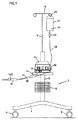
以下、図面を参照して本発明について説明するが、図1は、流体源22およびハンドヘルド電気外科デバイス30と組み合わされた電気外科ユニット14を有する本発明のシステムの一実施形態の正面図である。図1は、運搬を容易にするための四つの車輪6を備えた車台4を有する移動式カート2を示している。車台4は中空円柱ポストからなる垂直サポート部材8を支持するが、この垂直サポート部材8に対しては保管バスケット10を取り付け可能であり、そしてそれは、付加的な未使用デバイスと共に電気外科ユニットのユーザーマニュアルを保管するために使用される。さらにサポート部材8は、電気外科ユニット14の配置のための平坦で、安定した表面を提供するためにペデスタルテーブルからなるプラットフォーム12を支持している。
The present invention will now be described with reference to the drawings, wherein FIG. 1 is a front view of one embodiment of the system of the present invention having an
図示するように、カート2はさらに流体源支持ポール16を備えるが、その高さは、サポート部材8内で上下に支持ポール16をスライドさせ、その後、ネジセットを用いて適所で固定することによって調整可能である。流体源支持ポール16の上端にはクロスサポート18が存在するが、その端部には流体源22を支持するためのフックを提供するためにループ20が備わっている。
As shown in the figure, the
図1を参照すると、流体源22は流体バッグを具備し、ドリップチャンバー26の端部に配置されたスパイクをバッグに突き刺した後、そこから流体24がドリップチャンバー26を経て流れる。その後、流体24は、ハンドヘルド電気外科デバイス30までフレキシブルな供給管28を経て流れる。好ましくは、流体供給管28はポリマー素材から形成される。
Referring to FIG. 1, the
図1に示すように、流体供給管28はポンプ32を通っている。図示のとおり、ポンプ32は蠕動ポンプ、特にロータリー蠕動ポンプからなる。ロータリー蠕動ポンプに関しては、供給管28の一部は、公知の様式でポンプヘッドを昇降させることによって、ポンプヘッド内に装填される。図6に最もよく示されているように、機械的に、通常は、駆動シャフト55上で回転シリンダーそしてアンビルサポート58に対して管28を断続的に押し付けるピンチローラー57を回転させることによって生成される、管28の外部に生じる縮流波によって、流体24は供給管28内を運ばれる。これに代えて、ポンプ32はリニア蠕動ポンプからなっていてもよい。リニア蠕動ポンプに関して、機械的に、通常は、サポートに対して管28を順次押し潰す一連の加圧フィンガーあるいはパッドによって生成される、管28の外部に生じる縮流波によって、流体24は供給管28内を運ばれる。蠕動ポンプが概して好ましい。というのは、電気機械力機構(このものではローラーは電気モーターによって駆動される)は流体24と接触せず、したがって偶発的な汚染の可能性が低減されるからである。
As shown in FIG. 1, the
好ましい実施形態では、流体24は食塩水であり、さらに好ましくは通常(生理学的)食塩水からなる。本明細書では流体24として食塩水を挙げているが、その他の導電性流体を本発明に従って使用可能である。
In a preferred embodiment,
導電性流体が好ましいが、以下の説明から、より明らかとなるように、流体24はまた、非導電性流体からなっていてもよい。非導電性流体の使用は導電性流体ほど好ましいものではないが、非導電性流量の使用は、流体を完全に排除しかつ乾燥電極を使用した場合に比べて、依然として、たとえば、デバイス30の電極に対する組織固着の発生が軽減され、かつ、電極および/または組織の冷却が図れるといった利益をもたらす。それゆえ、たとえば純水など非導電性流体の使用を伴うこともまた、本発明の範疇に包含される。
Although a conductive fluid is preferred, as will become more apparent from the following description, the fluid 24 may also comprise a non-conductive fluid. The use of a non-conductive fluid is not as desirable as a conductive fluid, but the use of a non-conductive flow is still, for example, the electrode of
図1に示すように、電気外科デバイス30はケーブル34を介して電気外科ユニット14に接続されるが、このケーブル34は、複数の電気的に絶縁された導線と、その端部の少なくとも一つのプラグ36とを備える。電気外科ユニット14は電気外科デバイス30に対して、ケーブル34を介して、高周波(RF)エネルギー/パワー(電力)を供給する。図2に示すように、電気外科ユニット14のプラグレセプタクル38は、デバイス30を電気外科ユニット14に電気的に接続するために、その中にデバイス30のプラグ36を収容する。好ましくは、流体供給管28はケーブル34の一部として提供され、かつ、プラスチック同時押し出しによって電気的に絶縁された電線と共に製造される。
As shown in FIG. 1, the
図2は電気外科ユニット14の前面パネルを示している。パワースイッチ42は電気外科ユニット14をオン・オフするために使用される。電気外科ユニット14をオンにした後、RFパワー設定ディスプレイ44は、RFパワー設定をワット数で表示するのに使用される。好ましくは、パワー設定ディスプレイは液晶ディスプレイ(LCD)からなる。さらに、このディスプレイ44はエラーを表示するのに使用されるが、この場合、ディスプレイ44は、「Err」を示し、かつ、特別なエラーコードナンバーを示して交互に明滅する。
FIG. 2 shows the front panel of the
RFパワーセレクターはRFパワー設定スイッチ46a,46bからなるが、これはRFパワー設定値を選択するために使用される。スイッチ46aを押すとRFパワー設定値は増加し、一方、スイッチ46bを押すとRFパワー設定値は減少する。RFパワー出力は、20ないし100ワットの範囲では増加分5ワットで、そして100ないし200ワットの範囲では増加分10ワットで設定できる。さらに、電気外科ユニット14は、インジケーターライトを備えたRFパワー作動ディスプレイ74を具備してなるが、これはRFパワーが作用させられたときに点灯する。スイッチ46a,46bは薄膜スイッチからなっていてもよい。
The RF power selector consists of RF power setting switches 46a and 46b, which are used to select an RF power setting value. Pressing the
RFパワー設定ディスプレイを有することに加えて、電気外科ユニット14はさらに、流体流量設定ディスプレイを備える。流体流量設定ディスプレイは三つのインジケーターライト50a,50bおよび50cを備えるが、第1のライト50aは低い流体流量設定値に対応し、第2のライト50bは中程度(中間)の流体流量設定値に対応し、そして第3のライト50cは高い流体流量設定値に対応する。これら三つのインジケーターライトのうちの一つは、流体流量設定が選択された際に点灯する。
In addition to having an RF power setting display,
流量設定スイッチ52a,52bおよび52cを備えた流体流量セレクターは、流体流量設定値を選択すなわち切り換えるために使用される。三つのプッシュスイッチは、低い流体流量設定値に対応する第1のスイッチ52aと、中程度(中間)の流体流量設定値に対応する第2のスイッチ52bと、高い流体流量設定値に対応する第3のスイッチ52cとを備える。これら三つのスイッチのうちの一つを押すことで、低、中程度(中間)あるいは高のいずれかの対応する流体流量設定値が選択される。設定値が手動で選択されない場合に、デフォルト設定値として中程度(すなわち中間)の流体流量設定値が自動的に選択される。スイッチ52a,52bおよび52cは薄膜スイッチからなっていてもよい。
A fluid flow rate selector with flow
外科処置を開始する前に、デバイス30に流体24を充填しておくことが好ましい。プライミングは、流体24が存在しない状態でRFパワー作用を抑制するために望まれる。プライミングスイッチ54がデバイス30への流体24の充填を開始するために使用される。押込みスイッチ54を一度押すと、デバイス30に充填するために、所定時間にわたるポンプ32の動作が始まる。この時間が経過すると、ポンプ32は自動的に停止する。デバイス30への充填が始まると、インジケーターライトを備えたプライミングディスプレイ56がプライミングサイクルの間、点灯する。
The
前面パネル上で、双極作動ディスプレイ74は、(図1に示すように)デバイス30のハンドスイッチ162を、あるいはフットスイッチ(図示せず)を介して、RFパワーが電気外科ユニット14から作用させられたときに点灯する。引き出し76が電気外科ユニット14の下方に設けられるが、ここには、電気外科ユニット14のユーザー用の簡易ユーザーマニュアルが収容される。
On the front panel, the
図3は電気外科ユニット14の背面パネルを示している。電気外科ユニット14の背面パネルは、スピーカー60と、RFパワーが作用させられるときに聞こえる音(RFパワー作用音)のボリュームを調整するためのボリューム調整ノブ62とを備える。RFパワー作用音のボリュームは、ノブを時計回りに回転させることで増大し、そしてノブを反時計回りに回転させることで減少する。だが、電気外科ユニット14は、この音が完全に消されるのを阻止する。
FIG. 3 shows the back panel of the
電気外科ユニット14の背面パネルはまた、メインパワーコードを電気外科ユニット14に接続するのに使用されるパワーコードレセプタクル64と、適当なケーブルを用いて電気外科ユニット14をアースに接続するのに使用される等電位接地ラグコネクター66とを備える。背面パネルはまた、デバイス30のハンドスイッチに加えてフットスイッチによってRFパワーを作用させることができるように、電気外科ユニット14の内部フットスイッチ回路に接続可能な双極フットスイッチソケットの設置のための取り外し可能なキャップ68を備える。さらに、背面パネルはまたヒューズ引き出しを備えるが、これはライン電圧に適合した二つの余分なヒューズを備える。最後に、背面パネルは、電気外科ユニット14のモデル番号、シリアル番号、公称ライン電圧、周波数、電流およびヒューズ定格情報といった情報を提供し得るネームプレート72を備える。
The back panel of the
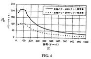
電気外科ユニット14のRFパワー出力カーブを図4に示す。インピーダンスZはX軸上にオームの単位で示され、かつ、出力パワーP0はY軸上にワットの単位で示されている。図示する実施形態では、双極電気外科パワー(RF)は200ワットに設定される。図に示すように、200ワットのRF出力設定値PSに関して、インピーダンスZが、30オームの低インピーダンスカットオフと125オームの高インピーダンスカットオフとの間に存在する限り、出力パワーP0は設定RFパワーPSと共に一定の値に留まる。30オームのインピーダンスZ以下では、出力パワーP0は、低インピーダンスランプによって示すように減少する。250オームのインピーダンスZ以上では、出力パワーP0はまた、高いインピーダンスランプによって示すように減少する。
The RF power output curve of the
電気外科ユニット14はまた、ポンプ速度を、したがってポンプによって送り出される流体の流量が、二つの入力変数、RF出力設定値および流体流量設定値に基づいて予め決定できるように構成される。図5は、Y軸上の立方センチメートル毎分(cc/min)単位の流体流量Qと、X軸上のワット単位のRFパワー設定値PSとの関係を示している。この関係は、組織の乾燥、電極の固着、焦げの形成および発煙といった望ましくない結果を阻止するべく、そして同時に、過度の流体および関連する電気的発散および電極‐組織インターフェースにおける冷却をもたらすほどには大きくない対応するRFパワー設定値PSにおける流体流量Qを実現するよう操作される。特定の理論に縛られないが、どのように流体流量が高周波パワーと相互作用するか、組織からの熱移送モード、流体の分別沸騰、およびさまざまな制御方式に関する、より詳細な説明は、2001年10月18日に発行され、かつ、本発明の譲受人に対して譲渡され、かつ、この引用によって矛盾を生じない範囲でその全体が本明細書中に組み込まれる米国特許出願公開第2001/0032002号に見出すことができる。
The
図示のとおり、電気外科ユニット14は、QL、QMおよびQHにそれぞれ対応する低、中程度および高の三つの流体流量設定値のそれぞれに関して、増大するRFパワー設定値PSと共に流体流体Qを直線的に増大させるよう構成されている。逆に、電気外科ユニット14は、QL、QMおよびQHにそれぞれ対応する低、中程度および高の三つの流体流量設定値のそれぞれに関して、減少するRFパワー設定値PSと共に流体流体Qを直線的に減少させるよう構成されている。図示のとおり、QL、QMおよびQHは、代表的比例定数を以下のように変更することによって、RFパワー設定値PSの関数として表せる。
QL = 0.1×PS
QM = 0.1286×PS
QH = 0.1571×PS
As shown, the
Q L = 0.1 × P S
Q M = 0.1286 × P S
Q H = 0.1571 × P S
図6は、ポンプ速度を、したがってポンプ32によって送り出される流体の流量を制御するために、電気外科ユニット14が、どのようにして、RFパワー設定値PSおよび流体流量設定値(QL、QMまたはQH)の入力を処理するかについての代表的なブロック図を示している。図示するように、プライミング機能の起動と同様、RFパワー設定値PSおよび(QL、QMおよびQHに対応する)低、中程度および高のいずれかの流体流量設定値に関するユーザー選択入力値は、電気外科ユニット14の前面パネル上に配置された、これらパラメーターに関する対応するスイッチを押すことによって、電気外科ユニット14に入力される。
FIG. 6 shows how the
図6に示すように、RFパワー設定スイッチ46a,46b、流量設定スイッチ52a,52b,52cおよびプライミングスイッチ54は全て、好ましくは、電気外科ユニット14内への入力を受ける(好ましくはプリント回路基板を具備してなる)ディスプレイパネルモジュール40の一部である。
As shown in FIG. 6, the RF
RFパワー、流体流量およびプライミングに関するユーザー選択入力値は、続いて、好ましくはコンピューターチップ45を含むプリント回路基板と高周波発生器47とポンプコントローラー48とを具備してなるメインモジュール43へと、対応する入力信号41を介して伝送される。図示するように、ディスプレイパネルモジュール40およびメインモジュール43は、他のコンポーネントと同様、パワー供給モジュール49からパワー(電力)を受け取るが、これもまたプリント回路基板からなる。
User selected input values for RF power, fluid flow rate and priming then correspond to a
コンピューターチップ45は、好ましくは、マイクロプロセッサーユニット、メモリーおよび入力/出力コントロールユニットを備える。こうして、高周波パワーレベルと流体の流量との間の関数的関係を、コンピューターチップ45のメモリーに記憶されることができる。この関数的関係は上記等式の形で記憶させることができるが、それらはまた、データベースルックアップテーブルの一部としての数値データポイントとして記憶させることができる。
The
図示するように、コンピューターチップ45が入力信号を受け、そしてそれを処理する。さらに詳しく言うと、たとえば、QL、QMまたはQHの流体流量設定値に対応する、受け取った入力信号から、コンピューターチップ45は、まず、上記等式のどれを適用するかを決定する。どの等式を適用するかを決定した後、コンピューターチップ45は、続いて、選択された高周波パワーレベルに基づいて、ポンプ32からの流体の流量に関する出力を特定するために上記関係を利用する。当該出力を特定したならば、コンピューターチップ45は続いて、選択された高周波パワーレベルおよびポンプ32からの流体の流量に関する算出された出力に対応する出力信号51および53をそれぞれ高周波発生器47およびポンプコントローラー48に送信する。その後、ポンプコントローラー48は、駆動シャフト55を回転させるポンプモーター61への入力電圧59を制御することによって、ポンプ駆動シャフト55の速度を制御する。代表的な電気外科ユニット14のより詳しい説明は、2006年7月6日に発行され、かつ、本発明の譲受人に対して譲渡され、かつ、この引用によって矛盾を生じない範囲でその全体が本明細書中に組み込まれる米国特許出願公開第2006/0149225号に見出すことができる。
As shown,
電気外科ユニット14は、処置後の冷却を実現するためにRFパワーが非作用状態とされた後、数秒間にわたって流体の流動を自動的に維持するために、タイマーのような遅延機構を備えていてもよい。電気外科ユニット14はまた、組織の乾燥、電極の固着、焦げの形成および発煙といった望ましくない結果が生じる可能性を排除するために、RFパワーが作用させられる前に、数秒まで流体流動を自動的に発生させるために、タイマーのような遅延機構を備えていてもよい。
The
電気外科ユニット14は、特に、双極デバイスと使用するための構造とされる。双極デバイスを用いた場合、デバイスの第1および第2の電極間に交流電流が生じる。本発明に係る電気外科ユニット14と組み合わせて使用される本発明に係る代表的な電気外科デバイスは、図7に、30aで示されている。本発明に係るさまざまな電気外科デバイスを電気外科ユニット14との使用に関連付けて説明するが、組み合わせに関する記述は本発明のシステムを説明するためのものであることを理解されたい。したがって、本明細書において開示する電気外科デバイスは電気外科ユニット14と共に使用するのに適しているが、単極デバイスなどの電気外科ユニット14と共に他の電気外科デバイスを使用することは妥当であり、あるいは電気外科ユニット14以外の他の電気外科ユニットと共に本明細書で開示した電気外科デバイスを使用することも妥当であることを理解されたい。
The
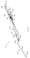
図7に示すように、代表的な双極電気外科デバイス30aは、剛性のある、自立式の中空シャフト102を備えた単一の定置アーム100を具備してなる。図示するように、シャフト102は好ましくは、その使用中、デバイス30aの遠位チップ部の良好な視界を提供するために屈曲している。シャフト102は、金属管から、さらに詳しくは厚肉皮下注射ステンレススチール管からなる。これによってシャフト102は、デバイス30aの使用中に捩れや大きな撓みが生じないようその形状を維持するのに、そして近位ハンドル104に対して固定関係で遠位部106を支持するのに十分な剛性を有する。他の実施形態では、シャフト102は、ポリマーあるいは複合素材といった非導電性素材から形成される。
As shown in FIG. 7, a typical bipolar
近位ハンドル104は、係合しているハンドル部104a,104bを具備してなる。ハンドル104は、好ましくは、ポリマーなどの殺菌可能な、剛性のある、非導電性素材から形成される。さらに、ハンドル104は、好ましくは、デバイス30aのユーザーがデバイス30aをペン型デバイスのように保持しかつ操作するのを容易にするために、デバイス30aの残部と共に細長く構成される。
デバイス30aは、好ましくは(図1に示すように)ドリップチャンバー26の端部に配置されたスパイクを介して流体源22に接続可能なフレキシブルな流体供給管28と、電気外科ユニット14に接続可能なケーブル34とを具備してなる(これらは、それぞれ遠位部106に流体およびRFパワーを供給する)。
The
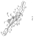
この実施形態では、デバイス30aのケーブル34は、(図8に示すように)三つの(雄型)プラグコネクター37a,37b,37cを介して電気外科ユニット14に接続可能な三つの絶縁された電線34a,34b,34cを具備してなる。プラグコネクター37a,37b,37cはそれぞれ、共通プラグハウジング36内で、電線34a,34b,34cおよび電線導体35a,35b,35cと組み合わされている。図8(これはハンドル104を取り外した状態でハンドル104の内部コンポーネントを示している)に最もよく示されているように、電線導体35aは、絶縁電線160aの電線導体158a(これは以下でさらに詳しく説明するように電極114aに対して遠位接続される)に対して、好ましくは溶着によって直に接合されている。やはり図8に示すように、電線34bの電線導体35bはまず、絶縁電線160bの電線導体158b(これは以下でさらに詳しく説明するように電極114bに対して遠位接続される)に接合(好ましくは溶着)される前に、ハンドスイッチアセンブリ162につながる。最後に、電線34cの電線導体35cは、好ましくはポリアセタールなどの剛性のあるポリマーからなるハンドスイッチ押しボタン164を押圧することでスイッチアセンブリ用の回路が閉じられたとき、パワーを提供するために、電気外科ユニット14に警告を出すようハンドスイッチアセンブリ162に接続されている。
In this embodiment, the
図8に加えて、スイッチアセンブリ162を図9および図10に示す。図10に最もよく示されているように、スイッチアセンブリ162は、押しボタン164と、二つの電気的コンタクトを有するドームスイッチ172とを備える。好ましくは、上側コンタクトは、平坦な下側コンタクトの上に重なると共にそれから離間させられたドーム状形態を備える。好ましくは、コンタクトは、ボタン164が非押圧ポジションにあるとき、上側コンタクトのドーム形状によって互いに離間し、これによってスイッチ172に関する開制御回路が形成される。だが、ボタンが押圧され、そして上側コンタクトがそれに対応して降下ポジションへと押圧されると、上側コンタクトは下側コンタクトと接触状態となり、ハンドスイッチ制御回路が閉じられる。制御回路が閉じられたことが電気外科ユニット14によって検出されると、電極114a,114bには電力が供給される。
In addition to FIG. 8, a
押圧力が上側コンタクトから解除されると、コンタクトは、その復元力すなわち弾性メモリーによって、その非押圧ドーム形状へと復帰するが、これによってボタン164はその非押圧ポジションへと復帰させられ、そしてハンドコントロール回路が再開放される。制御回路が開かれたことが電気外科ユニット14によって検出されると、電極114a,114bへの電力供給は停止させられる。スイッチアセンブリ162の機能のより詳しい説明は、2005年4月28日に発行され、かつ、本発明の譲受人に対して譲渡され、かつ、この引用によって矛盾を生じない範囲でその全体が本明細書中に組み込まれる米国特許出願公開第2005/0090816号に見出すことができる。
When the pressing force is released from the upper contact, the contact is restored to its non-pressing dome shape by its restoring force or elastic memory, which causes the
デバイス30aの使用中、血液および凝塊は、ボタン164とハンドル104との間の狭い間隙170に溜まる。図10に最もよく示すように、ボタン164は、周壁168によって画定されるハンドル104の孔166内に配置される。図示するように、ボタン164は、その側面に複数の開口163を備える。開口163は、ハンドル部104a,104bの周壁168に隣接するボタン164の側壁165の表面積を減少させる。したがって、ボタン164の側壁165の低減した表面積によって、押圧力がボタン164から解除されたとき、血液および凝塊によるボタン164のハンドル部104a,104bに対する固着が起きにくくなる。
During use of
図11に最もよく示すように、デバイス30aは、二つの双極電極114a,114bを備えるディスク状遠位端部を有する。ハウジング外側部分112およびハウジング内側部分116を備える絶縁体ハウジングアセンブリは、電極114a,114bをデバイス30aに固定している。ハウジング外側部分112およびハウジング内側部分116は、電気的絶縁素材、好ましくはポリマー、さらに好ましくはポリテトラフルオロエチレン(PTFE)などのフッ化ポリマーからなる。電気的絶縁体としての機能に加えて、ポリテトラフルオロエチレンは、それが、疎水性を有し、したがって手術中に存在する流体がその上に留まるのを阻止し、良好な耐アーク性を実現し、そして組織固着軽減のために低い摩擦係数を実現することから、好ましいものである。
As best shown in FIG. 11,
図12に示すように、ハウジング外側部分112は、金属シャフト102から電極114a,114bを電気的に絶縁している。図11および図12に示すように、ハウジング外側部分112は、近位円筒部118と遠位円筒部120とを備える。近位円筒部118は、遠位円筒部120よりも僅かに小さな外径を有するが、これによって両者間にはリム122が形成されている。組み立てのために、近位円筒部118は、ハウジング外側部分112をシャフト102に対して連結するためのコネクター部を提供する。図12に示すように、近位円筒部118の外径は、リム122がシャフト102の遠位端部110に当接した状態で、シャフト102の内腔124内に延在し、かつ、シャフト102の内径と嵌合するようなものとなっている。近位円筒部118の外径は、滑り嵌めを形成するようシャフト102の内径と嵌合するようになっているが、この場合、確実な連結状態を実現するために、円筒部118とシャフト102との間に接着剤あるいはその他の結合剤が使用され、あるいは別個の結合剤を必要としないプレス(締り)嵌めが利用される。
As shown in FIG. 12, the housing
図11および図12に示すように、ハウジング内側部分116は、電極114a,114bを、両者間にスペーサを提供することによって、互いに電気的に絶縁する。特に、ハウジング内側部分116は、電極114a,114b間に配置された遠位スペーサ部126を備える。組み立てのために、ハウジング内側部分116はさらに、このハウジング内側部分116をハウジング外側部分112に連結するための近位円筒部128を備える。図12に示すように、近位円筒部128の外径は、ハウジング外側部分112の内腔130内に延在し、かつ、内腔130の直径と嵌合するようなものとなっており、ハウジング外側部分112の遠位円筒部120が、ハウジング内側部分116および電極114a,114bの周りにカラーを提供する。近位円筒部128の外径は、滑り嵌めを形成するよう内腔130の直径と嵌合するようになっているが、この場合、確実な連結状態を実現するために、円筒部128とハウジング外側部分112との間に接着剤あるいはその他の結合剤が使用され、あるいは別個の結合剤を必要としないプレス(締り)嵌めが利用される。
As shown in FIGS. 11 and 12, the housing
上記に加えて、図11に最もよく示すように、ハウジング内側部分116の近位円筒部128は、それを経て電極114a,114bの脚部136a,136bが絶縁電線160a,160bの電線導体158a,158bと接続されるよう延在し得る、ハウジング外側部分112とハウジング内側部分116との間に、図12に示すように、二つの局所的間隙134a,134bを形成するために、その上に設けられた二つの対向する平坦面132a,132bを備える。
In addition to the above, as best shown in FIG. 11, the proximal
再び図11を参照すると、電極114a,114bの脚部136a,136bは、デバイス30aの遠位端部に配置されかつ同じ寸法および形状を有する二つの部分円形(半円形)電極部138a,138bから近位方向に延在している。これによって、互い対して電極によって呈示される電流密度は実質的に均一となる。やはり図示するように、部分円形電極部は互いの鏡像であり、かつ、それぞれ円の約半分の形状を有する。電極114a,114bは、好ましくは、導電性素材を具備してなるが、これはまた好ましくは非腐食性のものである。好ましい素材はステンレススチールである。他の好適な金属としては、チタニウム、金、銀および白金が挙げられる。
Referring again to FIG. 11, the legs 136a, 136b of the
図12に示すように、デバイス30aの遠位端部は平面状(平坦)であって、かつ、シャフト102の長手方向軸線と直交している。他の実施形態では、たとえば図13に示すように、デバイス30bの遠位端部は凸状となる。さらに他の実施形態では、たとえば図14に示すように、デバイス30cの遠位端部は凹状となる。
As shown in FIG. 12, the distal end of
図12を参照すると、ハウジング内側部116はまた、長手方向に向けられた直線状の止まり孔140と、円筒部128内で中央に位置させられたカウンター孔142とを備える。図示するように、流体供給管150の外径は、管の遠位端部がカウンター孔の底に当接した状態で、カウンター孔142内に延在し、かつ、カウンター孔142の直径と嵌合するようなものとなっている。流体供給管150の外径は、流体供給管150とハウジング内側部分116との間に液密シールを付与するために、接着剤あるいはその他の結合剤の使用を伴って確実な接続状態を実現するために、プレス(締り)嵌めを形成するようカウンター孔142の直径と嵌合するようなものとされてもよい。
Referring to FIG. 12, the housing
止まり孔140およびカウンター孔142に加えて、ハウジング内側部分116はまた直線状貫通孔144を備えるが、これは、孔140の遠位端部において孔140と直交すると共に円筒部128を貫通して延在している。図示するように、孔140および孔144は流体供給管150の内腔152と流体連通状態となっており、この流体供給管150の内腔152は、最終的に、流体供給管28の内腔29と流体連通状態となっている。これによって、孔140および孔144は、流体供給管28および150から供給される流体24のためのT形流体流路を提供するようになっている。
In addition to the
図11に示すように、孔144によって提供される流体通路からの流体をデバイス30aから放出するために、ハウジング外側部分12の円筒部120は二つの貫通孔146a,146bを備えるが、これらは孔144と整列しており、かつ、流体用の流体出口を付与する。図示するように、孔144は、遠位スペーサ部126と平行にハウジング内側部分を貫通して延在する。
As shown in FIG. 11, in order to release fluid from the fluid passage provided by the
図11に最もよく示すように、孔146a,146bはハウジング外側部分112のために使用される電気的絶縁材に設けられており、かつ、デバイスの遠位端部に近いデバイス30aの遠位部分に配置されている。これによって、孔146a,146bは、デバイス30aの使用中に目詰まりを生じないようになっている。すなわち、ハウジング外側部分112は導電性を持たず、しかも電極として機能しないので、組織および血液凝塊の、ハウジング外側部分112に対する固着が起きにくい。さらに、孔146a,146bはデバイスの遠位端部に近いデバイス30aの遠位部分に配置されているので、孔146a,146bが、概してデバイス30aの遠位端部に位置する血液にまみれた領域に直接露出させられるという状況は生じにくい。
As best shown in FIG. 11,
孔146a,146bおよび内腔144が目詰まりした場合、孔の一方および内腔144内にピン型構造体を差し込み、デバイス30a内を通過させ、他の孔からピンを突出させることによって、孔146a,146bおよび内腔144の目詰まりを解消し、きれいにすることができる。こうして、孔146a,146bおよび内腔144を目詰まりさせている物質は、ピンによって、そこから押し出され、除去される。
If the
やはり図11に示すように、孔146a,146bは、デバイス30aの対向する面に配置される。孔146aは、そのコーナー148aにおいて電極114aに隣接してかつ最接近して、そしてそのコーナー148bにおいて電極114bに隣接してかつ最接近して設けられる。孔146bは、そのコーナー149aにおいて電極114aに隣接してかつ最接近して、そしてそのコーナー149bにおいて電極114bに隣接してかつ最接近して設けられる。これによって、デバイス30aのための流体の必要性が最も高いと予期される電極114a,114bおよび組織の位置(すなわち電極コーナーおよびそれに隣接する組織)に流体が供給される。やはり、これによって、孔146a,146bからの流体は、電極114a,114bの部分円形側部周面151a,151bに供給される。図12に示すように、電極114a,114bの部分円形周面151a,151bは、組織に対して接触させられ、かつ、デバイス30aの遠位端部のかなりの部分の周りで周方向に延在している。図示するように、電極114aの部分円形周面151aはコーナー148aから電極114aのコーナー149aまで延在し、そして電極114bの部分円形周面151bはコーナー148bから電極114bのコーナー149bまで延在している。
As also shown in FIG. 11, the
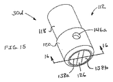
他の実施形態では、図15および図16に示すように、デバイス30d用の電極114a,114bの部分円形周面151a,151bは、電極114a,114bの部分円形周面151a,151bが組織を治療するために使用されないようにするために、好ましくは外側ハウジング部分112によって提供される電気的絶縁体によって覆われる。図示するように、電極114a,114bの部分円形周面151a,151bは、外側ハウジング部分112のリング状部分によって覆われる。
In another embodiment, as shown in FIGS. 15 and 16, the partial circular
デバイス30aの使用中、流体源22からの流体は、さまざまな構造体によって提供される流体通路を経て輸送される。流体源22からの流体24は、まず、供給管28の内腔29を経て輸送される。図8に示すように、流体24は続いて、ハンドル104内に配置されたサイズ低減ブッシュの内腔156内に供給され、続いて管150の内腔152内に供給されるが、管150は図12に示すようにシャフト102の内腔124内に収容されている。管150の内腔152から、流体24は続いて内腔140を通り、内腔144内へと流れ込み、そして孔146a,146bから放出される。本実施形態(これはぜん動ポンプ32を利用する)では、特にぜん動ポンプ32と一緒に作動するよう構成された(図7に示すような)特殊ポンプ管セグメント182が、供給管28の一部分間に継ぎ足され、そして、その各端部においてバーブド(barbed)流体ラインコネクター180を用いて、それに対して接続される。
During use of
さまざまな実施形態を通じて、電極114a,114bのための素材およびその表面と流体24との関係は、流体24が電極114a,114bの表面を濡らすようなものであるべきである。接触角θは、液体による固体のぬれの定量的目安である。それは、液体、気体および固体が交わる三つの相境界において液体によって形成される角度として幾何学的に規定される。関係する素材の熱力学に関して、接触角θは以下の式で与えられる三つの相間の界面自由エネルギーを伴う。
γLVcosθ=γSV−γSL
ここで、γLV、γSVおよびγSLはそれぞれ、液体/蒸気、固体/蒸気および固体/液体インターフェースの界面エネルギーを表す。接触角θが90度未満である場合、液体は固体をぬらすと言われる。接触角が90度超である場合、液体は非ぬれ性である。ゼロの接触角θは完全なぬれを表す。したがって、好ましくは、接触角は90度未満である。
Through various embodiments, the material for the
γ LV cosθ = γ SV -γ SL
Where γ LV , γ SV and γ SL represent the interfacial energy of the liquid / vapor, solid / vapor and solid / liquid interface, respectively. When the contact angle θ is less than 90 degrees, the liquid is said to wet the solid. If the contact angle is greater than 90 degrees, the liquid is non-wetting. A zero contact angle θ represents complete wetting. Therefore, preferably the contact angle is less than 90 degrees.
本明細書に開示された双極デバイスは、特に、手術中の血流遮断を実現する際の非癒合組織シーラーとして有用である。すなわち、組織の所望の血流遮断を実現するために、たとえば、コラーゲンおよび血管(たとえば動脈、静脈)の関係する内腔を収縮させ、これによってそこを通りかつそこからの血液の流れを阻止することによって、血液の損失を防止するために組織を収縮させ、凝固させ、そして塞ぐために、組織の把持は必要とされない。さらに詳しく言うと、本デバイスは、たとえば椎間板切除中に、(脊椎手術中に切断されようと切断されまいと)椎骨静脈および/または動脈系の血管のような血管を収縮させるのに有用である。 The bipolar devices disclosed herein are particularly useful as non-union tissue sealers in achieving blood flow blockage during surgery. That is, to achieve the desired blood flow blockage of the tissue, for example, the associated lumens of collagen and blood vessels (eg arteries, veins) are contracted, thereby preventing the flow of blood through and from there Thus, no tissue grasping is required to contract, coagulate and occlude the tissue to prevent blood loss. More particularly, the device is useful for constricting blood vessels such as vertebral veins and / or arterial blood vessels (whether or not cut during spinal surgery), for example during discectomy. .
椎骨板は、脊椎の椎骨間に堅固に固定された線維軟骨組織のフレキシブルなパッドである。板は、髄核と呼ばれる弾性コアを取り囲む、環状繊維質と呼ばれる、強靭な、繊維状の外膜からなる、概ね直径1インチで厚さ約0.25インチの平坦で円形の莢膜からなる。 The vertebral disc is a flexible pad of fibrocartilage tissue that is firmly fixed between the vertebrae of the spine. The plate consists of a flat, circular capsule approximately 1 inch in diameter and approximately 0.25 inch thick, consisting of a tough, fibrous outer membrane, called annular fiber, surrounding an elastic core called the nucleus pulposus .
応力下では、髄核が膨らみかつヘルニアを形成し、板の環状繊維膜の弱い部分を経て脊柱管内に突き出す可能性がある。したがって、髄核物質の全てまたは一部は弱い場所を貫通して突出し、周囲の神経を圧迫し、これによって痛み生じ、そして動作が不自由となる。 Under stress, the nucleus pulposus bulges and forms a hernia, which can protrude into the spinal canal through the weak portion of the annular fiber membrane of the plate. Thus, all or part of the nucleus pulposus material protrudes through weak areas, compressing the surrounding nerves, thereby causing pain and impeding movement.
椎間板切除ならびに上および下椎骨の椎体のその後の癒合の一部として患者から損傷した椎間板を除去する必要がある場合、本発明に係るデバイスは、椎骨静脈および/または動脈系の血管を収縮させ塞ぐために特に有用である。 When it is necessary to remove an injured disc from a patient as part of a discectomy and subsequent fusion of the vertebral bodies of the upper and lower vertebrae, the device according to the present invention constricts the vertebral vein and / or arterial vessels. Especially useful for plugging.
椎骨静脈系は、脊柱を取り囲む四つの相互連結された静脈ネットワークのいずれかを備える。これらは、前方外側椎骨静脈集網叢(椎体の周囲の系)、後方外側椎骨静脈集網叢(椎骨突起の周囲の系)、前方内側椎骨(硬膜外)静脈集網叢(硬膜の前方の椎管の長さにわたる系)および後方内側椎骨(硬膜外)静脈集網叢(硬膜の後方の椎管の長さにわたる系)として知られ、後者の二つは硬膜外静脈集網叢を構成している。外側椎骨静脈集網叢の静脈は、椎骨間静脈ならびに各椎骨レベルの前方および後方分節状延髄/小根静脈を介して内側椎骨静脈集網叢の静脈とつながっている。 The vertebral venous system comprises any of the four interconnected venous networks that surround the spinal column. These are the anterior lateral vertebral venous plexus (system around the vertebral body), the posterior lateral vertebral venous plexus (system around the vertebral process), the anterior medial vertebra (epidural) venous plexus (dura mater) Known as the vertebral anterior vertebral length) and posterior medial vertebra (epidural) venous plexus (system spanning the vertebral length behind the dura), the latter two being epidural It constitutes the venous collection plexus. The veins of the lateral vertebral venous plexus are connected to the veins of the medial vertebral venous plexus via intervertebral veins and anterior and posterior segmental medullary / radix veins at each vertebral level.
椎骨前方系は脊柱の分節動脈を含むが、これは、さまざまな椎骨レベルの前方および後方小根動脈に供給する。胸郭および腰椎領域では、分節動脈は、前方肋間、肋骨下および腰椎動脈を含むが、これは大動脈の前方様態に起因する。脊柱への血液供給は分節上動脈によってなされるが、これは二つのネットワークに供給する(すなわち一方は、椎骨の骨要素、脊髄付近の筋肉、および硬膜外スペースに供給し、そして他方、内側ネットワークは脊髄自体に栄養分を与える)。 The anterior vertebral system includes the segmental arteries of the vertebral column, which feed the anterior and posterior root arteries at various vertebral levels. In the thoracic and lumbar regions, the segmental arteries include the anterior intercostal, subcostal and lumbar arteries, which are due to the anterior aspect of the aorta. Blood supply to the spinal column is made by the superior arterial artery, which supplies two networks (i.e., one supplies the vertebral bone elements, the muscle near the spinal cord, and the epidural space, and the other medial The network nourishes the spinal cord itself).
大動脈から延在して、分節動脈は椎骨の椎体の周囲に張り付いており、それが神経孔に達するとき、椎骨付近吻合吻合、椎前吻合および主脊椎ブランチへと分岐する。この主脊椎ブランチは椎骨の横断突起下で後方に延在しており、椎骨の後方要素の骨および傍脊髄筋肉に供給する。その起点から僅かに離れたところで、脊椎ブランチは脊髄ブランチに枝分かれするが、これは前方小根動脈および前方分節延髄動脈に供給し、これは最終的に前方脊柱動脈に供給する。脊柱ブランチはまた、椎体および硬膜へのブランチ、および最終的に後方脊柱動脈に供給する後方小根動脈に供給する。 Extending from the aorta, the segmental artery sticks around the vertebral body of the vertebra, and when it reaches the nerve hole, it branches into the near-vertebral anastomosis, anterior vertebral anastomosis, and the main spinal branch. This main spine branch extends posteriorly under the transverse process of the vertebrae and feeds the bone and paraspinal muscles of the posterior element of the vertebrae. At some distance from its origin, the spinal branch branches into a spinal cord branch that feeds the anterior root and anterior segmental medullary arteries, which ultimately feeds the anterior spinal artery. The spinal branch also feeds into the vertebral body and the dura, and the posterior radicular artery that ultimately feeds the posterior spinal artery.
後方椎間板切除の間、本発明のデバイスは、とりわけ、椎間板スペースに入り込む前に、後方外側椎骨静脈集網叢、後方内側椎骨(硬膜外)静脈集網叢および前方内側椎骨(硬膜外)静脈集網叢の血管を塞ぐために外科医によって使用される。これに代えて、前方椎間板切除の間、本発明のデバイスは、とりわけ、前方外側椎骨静脈集網叢の静脈および分節動脈、特に椎体に隣接する前方および側前方部分を塞ぐために外科医によって使用される。 During posterior discectomy, the device of the present invention, among other things, before entering the disc space, posterior lateral vertebral venous plexus, posterior medial vertebra (epidural) venous plexus and anterior medial vertebra (epidural) Used by surgeons to occlude blood vessels in the venous plexus. Alternatively, during anterior discectomy, the device of the present invention is used by surgeons, among other things, to occlude the venous and segmental arteries of the anterior lateral vertebral venous plexus, especially the anterior and lateral anterior portions adjacent to the vertebral body. The
椎間板切除の間、血管は、たいてい、切込みが入れられ、裂かれ、あるいはその他の方法で切断される。こうした血管は出血し、その結果生じる血液は組織治療場所へと流れ込み、視認性を悪化させ、そして処置を長引かせる。本発明に係る方法は、血管に切込みが入れられ、裂かれ、あるいはその他の方法で切断される前に、血液の損主を防止するために、そうした椎骨血管を塞ぐのに使用可能である。本発明は、血管の押し潰された部分を得るために、本発明に係るデバイスのような外科デバイスによって支持脊椎構造体に対して血管の一部を押し付けることと、外科デバイスを血管から分離させた後に血管を通る血流を阻止するために、(たとえば、血管のコラーゲンの収縮によって血管および内腔を収縮させること、および/またはコラーゲン結合によって内腔の対向する内面を一つに結合することによって)血管を塞ぐのに十分な程度まで外科デバイスを用いて血管の押し潰された部分を加熱することとを具備する。 During discectomy, the blood vessels are often incised, torn, or otherwise cut. These blood vessels bleed and the resulting blood flows into the tissue treatment site, worsening visibility and prolonging the procedure. The method according to the present invention can be used to occlude such vertebral blood vessels to prevent blood loss before the blood vessels are cut, torn or otherwise cut. The present invention is directed to pressing a portion of a blood vessel against a supporting spinal structure by a surgical device, such as a device according to the present invention, to separate the surgical device from the blood vessel to obtain a collapsed portion of the blood vessel. To block blood flow through the blood vessel after a period of time (e.g., contracting the blood vessel and lumen by contraction of the collagen of the blood vessel, and / or joining the opposing inner surfaces of the lumen together by collagen binding) Heating the collapsed portion of the blood vessel using a surgical device to a degree sufficient to occlude the blood vessel.
それに対して血管が押し付けられる支持脊柱構造体は、脊柱の一つ以上の椎骨からなり、あるいはさらに、椎骨の椎体を具備してなる。椎骨は、頚椎椎骨、胸髄椎骨あるいは腰髄椎骨の一つからなる。椎骨に加えて、支持構造体はまた、前方縦靭帯あるいは後方縦靭帯といった脊柱靭帯、あるいは椎間板からなる。 The supporting vertebral column structure against which the blood vessel is pressed consists of one or more vertebrae of the vertebral column, or further comprises vertebral vertebral bodies. The vertebra consists of one of a cervical vertebra, a thoracic vertebra, or a lumbar vertebra. In addition to the vertebrae, the support structure also consists of a spinal ligament, such as an anterior or posterior longitudinal ligament, or an intervertebral disc.
処置の種類に依存して、支持脊柱構造体はさらに、椎骨の椎体の前方側あるいは椎骨の椎体の側方前方側を具備してなるが、これは、前方アプローチの間に遭遇するであろう。後方アプローチに関して、支持脊柱構造体はさらに、椎骨の椎体の後方側あるいは椎骨の椎体の側方後方側を具備してなる。前方および後方アプローチは、内視鏡脊柱手術、腹腔鏡脊柱手術あるいは開口脊柱手術の一部であってもよい。 Depending on the type of procedure, the supporting spine structure further comprises an anterior side of the vertebral vertebral body or a lateral anterior side of the vertebral vertebral body, which may be encountered during an anterior approach. I will. With respect to the posterior approach, the supporting spine structure further comprises a posterior side of the vertebral vertebral body or a lateral posterior side of the vertebral vertebral body. The anterior and posterior approaches may be part of endoscopic spinal surgery, laparoscopic spinal surgery or open spinal surgery.
椎骨の剛性および椎骨の安定性に起因して、血管を、椎骨の変形を伴わずに、椎骨に対して押し付けることができる。これによって、血管は押し潰され、この時、血管の押し潰された部分は、外科デバイスが血管から取り出された後に血管を塞ぐのに十分な程度まで加熱される。 Due to the stiffness of the vertebra and the stability of the vertebra, the blood vessel can be pressed against the vertebra without vertebral deformation. This causes the vessel to be crushed, at which time the crushed portion of the vessel is heated to a degree sufficient to occlude the vessel after the surgical device is removed from the vessel.
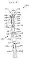
図17は、シャフト102の長手方向軸線が垂直に配置され、かつ、デバイス30aの遠位端部が組織治療場所に面する状態で、デバイス30aの遠位部分106(デバイス30b〜30dに関しても同様)が、使用のためにどのように向けられ得るかを示している。他の実施形態では、デバイス30aは、シャフト102の長手方向軸線が水平方向に向けた状態で、あるいは垂直と水平との間の向きで使用できる。
FIG. 17 illustrates that the
図17は、デバイス30aと組織200とを、その治療前の状態で示している。図示するように、組織200は、血管220を、さらに詳しくは硬膜外静脈を有している。血管220の下方に存在するのが靭帯230であり、さらに詳しくは、脊椎の長手方向靭帯である。靭帯の下方に存在するのは椎骨232であり、さらに詳しくは椎骨232の椎体である。
FIG. 17
図18は、血管220の押し潰された部分を得るために、支持脊椎構造体(ここでは靭帯230および椎骨232)に対して血管220の一部を押し付けるために、そのユーザーによってデバイス30aに対して十分な力および圧力が加えられた状態で、組織200に対して作用させられたデバイス30aを示している。ある実施形態では、デバイス30aは、力あるいは圧力ゲージのようなフィードバック機構を備えるが、これは、十分な力/圧力が血管220に加えられたときデバイスのユーザーに警告を発する。他の実施形態では、フィードバック機構は、作動するライトを備える。図示するように、デバイス30aの電極114a,114bは、ハウジング内側部分116の遠位スペーサ部分の幅だけ、組織200の隣接組織表面202から離間している。
FIG. 18 shows the
図19は、組織200の表面202と電極114a,114bとの間に局所的な流体カップリング204を付与するために電極114a,114bへと遠位方向に流れる、孔146a,146bから放出される流体24と共に使用中のデバイス30aを示している。好ましくは、流体24は、電極114a,114bの周面151a,151bと、デバイス30aの遠位端部に置かれた電極114a,114bの平坦な部分円形電極部138a,138bとの両方において、電極114a,114bと組織200とをつなぐ。同時に、RF電気エネルギー/パワー(電界線206によって示す)が、組織表面202において組織200へと、そして組織表面202の下では流体24を介して組織200へと供給される。
FIG. 19 is released from
電極114a,114bは、RFエネルギー/パワーを供給し、組織200中に交流電流電界を形成するために電気外科ユニット14に接続される。交流の存在下で、電極114a,114bは、正電荷から負電荷への電流の流れを伴って正電荷と負電荷との間で極性が変化する。特定の理論に縛られることなく、組織の加熱は電気抵抗加熱によってなされる。すなわち、組織の温度は、電気エネルギーが電圧から吸収され、組織の電気抵抗の関数としてイオンの加速された移動によって熱エネルギー(すなわち熱)へと変換されながら、組織を流れる電流によって増大する。
The
デバイス30aによる血管220の押し潰された部分の加熱は、デバイス20aを血管220から分離させた後に血管220を通って血液が流れるのを阻止するために、少なくとも部分的に血管220を塞ぐのに十分なものである。ここで、これは、血管220のコラーゲンを収縮させるのに十分な程度まで血管220を加熱し、これによって血管220および血管220の内腔222を収縮させることによってなされる。これはまた、(ここではコラーゲン結合によって)内腔222の対向する内面224および226を一つに結合するために、血管220の押し潰された部分に対して十分な熱および圧力を加えることによってなされる。
Heating the crushed portion of
血管のようなTypeIコラーゲンを含む組織を収縮させるための時間は、概して、時間に依存する。たとえば、TypeIコラーゲンは、約85℃の温度にさらされたとき約0.01秒の曝露時間で、約75℃の温度にさらされたとき約1秒の曝露時間で、約70℃の温度にさらされたとき約10秒の曝露時間で、そして約65℃の温度にさらされたとき約15分の曝露時間で収縮する。組織加熱のための代表的な目標温度/時間は約75℃で1秒である。規定された他の方法では、便宜上、RF処理の後、約1秒ないし10秒の間で、それを含む範囲で、コラーゲンを収縮させるのに十分な程度まで組織を加熱すべきである。 The time for contracting tissue containing Type I collagen, such as blood vessels, is generally time dependent. For example, Type I collagen can reach a temperature of about 70 ° C. with an exposure time of about 0.01 seconds when exposed to a temperature of about 85 ° C. and an exposure time of about 1 second when exposed to a temperature of about 75 ° C. Shrink with an exposure time of about 10 seconds when exposed and with an exposure time of about 15 minutes when exposed to a temperature of about 65 ° C. A typical target temperature / time for tissue heating is about 75 ° C. for 1 second. In other defined methods, for convenience, the tissue should be heated to an extent sufficient to cause the collagen to contract, including and within about 1 to 10 seconds after RF treatment.
流体24は、デバイス30aと組織200との間の電気カップリングを提供することに加えて、電極114a,114bが組織200に固着するのを阻止するために組織200の表面202を冷却しかつ潤滑する。デバイス30aの遠位端部および組織治療位置における流体の量しだいで、流体カップリング204は、デバイス30aの遠位端部を取り囲むシングルカップリングから、あるいは、孔146a,146bに最も近接したデバイスの各側に配置された複数の別個のカップリングからなる。
In addition to providing electrical coupling between the
デバイス30a用の流体カップリングはまた、組織200の表面上に存在しかつ電極114a,114b間のシャント(shunt)を形成する導電性流体ブリッジからなることもある。この場合、ある量のRFエネルギーは、組織200に流れ込まなくなり、導電性流体ブリッジを介して電極114a,114b間を実際に通過する。RFエネルギーのこの損失は、組織を治療するプロセスを遅らせる。だが、デバイス30aに関して、電極114a,114bの対向するコーナー148aおよび148bおよび/または対向するコーナー149a,149b間にそれぞれ配された、このカップリングを有することが好ましい。というのは、これらコーナーに隣接する組織は、電極形態に起因して、治療されている他の組織よりも、より素早く温度が上昇し、あるいはより高温になるからである。そうした場合、こうした位置に流体カップリング204を備えることで、組織200のよりバランスのとれた加熱および治療が可能となる。したがって、組織から熱を放散させるために流体の小部分が沸騰し、その一方で同時に、流体が、治療されている他の組織よりも、より素早く温度が上昇しあるいはより高温になる位置において、ある量のRFエネルギーが組織200に送り込まれるのを妨げるような量だけ、流体24をデバイス30aから供給することが好ましいであろう。
The fluid coupling for
図20は、血液損失およびそこを通る血流が生じないように血管220を塞いだ状態で、組織200から分離させられたデバイス30aを示している。
FIG. 20 shows the
上述したように、本発明に係る双極デバイスは、組織乾燥、電極固着、焦げの発生、および発煙といった、そうした望ましくない結果を阻止し、したがって従来のドライチップ電気外科デバイスと同じ欠点は持たない。上記デバイスの使用は、外科手術中の血液損失を十分に僅かなものとすることができる。そうした血液損失の低減によって、輸血の必要性を、したがって輸血に関するコストおよび好ましくない臨床的な帰結、たとえば長期入院を低減あるいは排除できる。 As mentioned above, the bipolar device according to the present invention prevents such undesirable consequences such as tissue drying, electrode sticking, scorching, and fuming and therefore does not have the same drawbacks as conventional dry tip electrosurgical devices. The use of the device can minimize blood loss during surgery. Such reduction of blood loss can reduce or eliminate the need for blood transfusion, and therefore the costs and undesirable clinical consequences of blood transfusion, such as long-term hospitalization.
本発明の好ましい実施形態について説明してきたが、本発明の趣旨および特許請求の範囲の記載から逸脱することなく、さまざまな変更、適合および改変をなし得ることを理解されたい。本発明の範囲は、それゆえ、上記説明によってではなく、その代わりに特許請求の範囲の記載およびそれと同等のものによって特定される。さらに、特許請求の範囲は必ずしも、出願人が権利主張するために呈した本発明の最も広い範囲、あるいは本発明が特許請求する様式のみを含むものではないこと、あるいは全ての言及された特徴が必須であることを理解されたい。 While preferred embodiments of the invention have been described, it will be appreciated that various changes, adaptations and modifications can be made without departing from the spirit of the invention and the appended claims. The scope of the invention is, therefore, not to be determined by the above description, but instead by the claims and their equivalents. Further, the claims do not necessarily include the broadest scope of the invention as claimed by the applicant, or the claims that the invention claims, or all the features mentioned. Please understand that it is essential.
本明細書において引用した全ての刊行物および特許文献は、矛盾を生じない範囲で、あらゆる目的のために、この引用によって、その全体が本明細書に組み込まれる。 All publications and patent documents cited herein are hereby incorporated by reference in their entirety for all purposes to the extent that they do not conflict.
2 移動式カート
4 車台
6 車輪
8 垂直サポート部材
10 保管バスケット
12 プラットフォーム
14 電気外科ユニット
16 流体源支持ポール
18 クロスサポート
20 ループ
22 流体源
24 流体
26 ドリップチャンバー
28 供給管
29 内腔
30 ハンドヘルド電気外科デバイス
30a 双極電気外科デバイス
32 ポンプ
34 ケーブル
34a,34b,34c 電線
35a,35b,35c 電線導体
36 プラグ
37a,37b,37c プラグコネクター
38 プラグレセプタクル
40 ディスプレイパネルモジュール
41 入力信号
42 パワースイッチ
43 メインモジュール
44 RFパワー設定ディスプレイ
45 コンピューターチップ
46a,46b RFパワー設定スイッチ
47 高周波発生器
48 ポンプコントローラー
49 パワー供給モジュール
50a,50b,50c インジケーターライト
51,53 出力信号
52a,52b,52c 流量設定スイッチ
54 プライミングスイッチ
55 駆動シャフト
56 プライミングディスプレイ
57 ピンチローラー
58 アンビルサポート
59 入力電圧
60 スピーカー
61 ポンプモーター
62 ボリューム調整ノブ
64 パワーコードレセプタクル
66 等電位接地ラグコネクター
68 キャップ
72 ネームプレート
74 RFパワー作動ディスプレイ
76 引き出し
100 定置アーム
102 中空シャフト
104 近位ハンドル
104a,104b ハンドル部
106 遠位部
110 遠位端部
112 ハウジング外側部分
114a,114b 電極
116 ハウジング内側部分
118 近位円筒部
120 遠位円筒部
122 リム
124 内腔
126 遠位スペーサ部
128 近位円筒部
130 内腔
132a,132b 平坦面
134a,134b 局所的間隙
136a,136b 脚部
138a,138b 部分円形電極部
140 止まり孔
142 カウンター孔
144 直線状貫通孔
146a,146b 貫通孔
148a,148,149a,149b コーナー
150 流体供給管
151a,151b 部分円形側部周面
152 内腔
158a,158b 電線導体
160a,160b 絶縁電線
162 ハンドスイッチアセンブリ
163 開口
164 ハンドスイッチ押しボタン
165 側壁
166 孔
168 周壁
170 間隙
172 ドームスイッチ
180 バーブド流体ラインコネクター
182 特殊ポンプ管セグメント
200 組織
202 隣接組織表面
204 流体カップリング
220 血管
224,226 内腔の対向する内面
230 靭帯
232 椎骨
2 Mobile Cart 4 Chassis 6 Wheels 8 Vertical Support Member 10 Storage Basket 12 Platform 14 Electrosurgical Unit 16 Fluid Source Support Pole 18 Cross Support 20 Loop 22 Fluid Source 24 Fluid 26 Drip Chamber 28 Supply Pipe 29 Lumen 30 Handheld Electrosurgical Device 30a Bipolar Electrosurgical Device 32 Pump 34 Cable 34a, 34b, 34c Electric Wire 35a, 35b, 35c Electric Wire Conductor 36 Plug 37a, 37b, 37c Plug Connector 38 Plug Receptacle 40 Display Panel Module 41 Input Signal 42 Power Switch 43 Main Module 44 RF Power Setting display 45 Computer chip 46a, 46b RF power setting switch 47 High frequency generator 48 Pump controller 49 Power supply module 50a, 50b, 50c Indicator light 51, 53 Output signal 52a, 52b, 52c Flow rate setting switch 54 Priming switch 55 Drive shaft 56 Priming display 57 Pinch roller 58 Anvil support 59 Input voltage 60 Speaker 61 Pump motor 62 Volume adjustment knob 64 Power cord receptacle 66 Equipotential ground lug connector 68 Cap 72 Name plate 74 RF power actuation display 76 Drawer 100 Stationary arm 102 Hollow shaft 104 Proximal handle 104a, 104b Handle portion 106 Distal portion 110 Distal end portion 112 Housing outer portion 114a, 114b Electrode 116 Housing inner portion 118 Proximal cylindrical portion 120 Distal cylindrical portion 122 Rim 24 lumen 126 distal spacer portion 128 proximal cylindrical portion 130 lumen 132a, 132b flat surface 134a, 134b local gap 136a, 136b leg portion 138a, 138b partial circular electrode portion 140 blind hole 142 counter hole 144 linear through hole 146a, 146b Through-hole 148a, 148, 149a, 149b Corner 150 Fluid supply pipe 151a, 151b Partial circular side peripheral surface 152 Lumen 158a, 158b Wire conductor 160a, 160b Insulated wire 162 Hand switch assembly 163 Opening 164 Hand switch push button 165 Side wall 166 Hole 168 Perimeter wall 170 Gap 172 Dome switch 180 Barbed fluid line connector 182 Special pump tube segment 200 Tissue 202 Adjacent tissue surface 204 Fluid coupling 220 Blood Tubes 224,226 Opposite inner surface of lumen 230 Ligament 232 Vertebral
Claims (12)
前記デバイスは、
ハンドルと、
前記ハンドルから遠位方向に延在するシャフトであって、前記ハンドルに対して固定関係で前記デバイスの前記遠位部分を支持するシャフトと、
前記流体の流体源に接続可能な流体供給通路と、
前記流体供給通路と流体連通状態にあり、かつ、前記デバイスの前記遠位部分において前記デバイスの外部に前記流体を供給するよう構成された少なくとも一つの流体出口と、
を具備し、
前記デバイスの前記遠位部分は前記デバイスの遠位端部において終端をなしており、前記デバイスの前記遠位端部はディスク形遠位端部を具備してなり、
前記ディスク形遠位端部は、第1の電極を形成する第1の半ディスクおよび第2の電極を形成する第2の半ディスクを具備してなり、
前記第1の電極は、前記電極の周面の半円の形状の部分の一つの端点によって形成された第1の電極の第1のコーナーと、前記電極の周面の半円の形状の部分の別の端点によって形成された第1の電極の第2のコーナーとを具備してなり、
前記少なくとも一つの流体出口は、前記第1の電極の第1のコーナーおよび前記第1の電極の第2のコーナーの一つにおいて、前記第1の電極に最も近接していることを特徴とするデバイス。 A bipolar electrosurgical device for treating tissue in the presence of radio frequency power and fluid supplied simultaneously from a distal portion of the device, comprising:
The device is
A handle,
A shaft extending distally from the handle, the shaft supporting the distal portion of the device in a fixed relationship relative to the handle;
A fluid supply passage connectable to a fluid source of the fluid;
At least one fluid outlet in fluid communication with the fluid supply passage and configured to supply the fluid to the exterior of the device at the distal portion of the device;
Comprising
The distal portion of the device terminates at the distal end of the device, the distal end of the device comprising a disc-shaped distal end;
It said disk-shaped distal end, Ri greens comprises a second half-disc forming the first half disc and the second electrode forming the first electrode,
The first electrode includes a first corner of the first electrode formed by one end point of a semicircular portion of the circumferential surface of the electrode, and a semicircular portion of the circumferential surface of the electrode. A second corner of the first electrode formed by another end point of
The at least one fluid outlet is closest to the first electrode at one of a first corner of the first electrode and a second corner of the first electrode. device.
前記第2の電極は、概ね第2の半円の形状の周面を有することを特徴とする請求項1に記載のデバイス。 The first electrodes, as well as having a generally circumferential surface of the shape of the first semicircle,
The second electrodes are generally device according to claim 1, characterized in that it comprises a circumferential surface of the shape of the second semicircle.
第2の電極部分円形周面は露出させられていることを特徴とする請求項1に記載のデバイス。 The first electrode portion circular circumferential surface is exposed, and
The device according to claim 1 , wherein the second electrode portion circular circumferential surface is exposed.
前記第2の電極部分円形周面は電気的絶縁体によって覆われていることを特徴とする請求項1に記載のデバイス。 The first electrode portion circular circumferential surface is covered by an electrical insulator; and
The device according to claim 1 , wherein the second electrode portion circular circumferential surface is covered with an electrical insulator.
Applications Claiming Priority (3)
| Application Number | Priority Date | Filing Date | Title |
|---|---|---|---|
| US89676807P | 2007-03-23 | 2007-03-23 | |
| US60/896,768 | 2007-03-23 | ||
| PCT/US2008/057815 WO2008118777A2 (en) | 2007-03-23 | 2008-03-21 | Surgical devices and methods of use thereof |
Publications (3)
| Publication Number | Publication Date |
|---|---|
| JP2010522045A JP2010522045A (en) | 2010-07-01 |
| JP2010522045A5 JP2010522045A5 (en) | 2011-07-07 |
| JP5430409B2 true JP5430409B2 (en) | 2014-02-26 |
Family
ID=39789243
Family Applications (1)
| Application Number | Title | Priority Date | Filing Date |
|---|---|---|---|
| JP2009554767A Expired - Fee Related JP5430409B2 (en) | 2007-03-23 | 2008-03-21 | Surgical device and method of use thereof |
Country Status (6)
| Country | Link |
|---|---|
| US (2) | US8216233B2 (en) |
| EP (1) | EP2129313B1 (en) |
| JP (1) | JP5430409B2 (en) |
| CN (1) | CN101677812B (en) |
| ES (1) | ES2394719T3 (en) |
| WO (1) | WO2008118777A2 (en) |
Families Citing this family (58)
| Publication number | Priority date | Publication date | Assignee | Title |
|---|---|---|---|---|
| US8048070B2 (en) | 2000-03-06 | 2011-11-01 | Salient Surgical Technologies, Inc. | Fluid-assisted medical devices, systems and methods |
| WO2003024349A1 (en) | 2001-09-05 | 2003-03-27 | Tissuelink Medical, Inc. | Fluid-assisted medical devices, systems and methods |
| ES2643763T3 (en) * | 2000-03-06 | 2017-11-24 | Salient Surgical Technologies, Inc. | Fluid supply system and controller for electrosurgical devices |
| US6907884B2 (en) | 2002-09-30 | 2005-06-21 | Depay Acromed, Inc. | Method of straddling an intraosseous nerve |
| US7258690B2 (en) | 2003-03-28 | 2007-08-21 | Relievant Medsystems, Inc. | Windowed thermal ablation probe |
| US8361067B2 (en) | 2002-09-30 | 2013-01-29 | Relievant Medsystems, Inc. | Methods of therapeutically heating a vertebral body to treat back pain |
| EP2227174B1 (en) | 2007-12-28 | 2019-05-01 | Salient Surgical Technologies, Inc. | Fluid-assisted electrosurgical device |
| US9358063B2 (en) | 2008-02-14 | 2016-06-07 | Arthrocare Corporation | Ablation performance indicator for electrosurgical devices |
| AU2009296474B2 (en) | 2008-09-26 | 2015-07-02 | Relievant Medsystems, Inc. | Systems and methods for navigating an instrument through bone |
| US10028753B2 (en) | 2008-09-26 | 2018-07-24 | Relievant Medsystems, Inc. | Spine treatment kits |
| US8137345B2 (en) | 2009-01-05 | 2012-03-20 | Peak Surgical, Inc. | Electrosurgical devices for tonsillectomy and adenoidectomy |
| US9254168B2 (en) | 2009-02-02 | 2016-02-09 | Medtronic Advanced Energy Llc | Electro-thermotherapy of tissue using penetrating microelectrode array |
| EP2398416B1 (en) | 2009-02-23 | 2015-10-28 | Medtronic Advanced Energy LLC | Fluid-assisted electrosurgical device |
| CN102497832B (en) | 2009-09-08 | 2015-09-09 | 显著外科技术公司 | For case assembly and the using method thereof of electro-surgical device, electrosurgical unit |
| US8372067B2 (en) * | 2009-12-09 | 2013-02-12 | Arthrocare Corporation | Electrosurgery irrigation primer systems and methods |
| EP2523620B1 (en) | 2010-01-15 | 2019-06-19 | Medtronic Advanced Energy LLC | Electrosurgical device |
| US9585709B2 (en) * | 2010-02-05 | 2017-03-07 | Covidien Lp | Square wave for vessel sealing |
| US9592090B2 (en) | 2010-03-11 | 2017-03-14 | Medtronic Advanced Energy Llc | Bipolar electrosurgical cutter with position insensitive return electrode contact |
| US20110295249A1 (en) * | 2010-05-28 | 2011-12-01 | Salient Surgical Technologies, Inc. | Fluid-Assisted Electrosurgical Devices, and Methods of Manufacture Thereof |
| US9138289B2 (en) * | 2010-06-28 | 2015-09-22 | Medtronic Advanced Energy Llc | Electrode sheath for electrosurgical device |
| US8920417B2 (en) | 2010-06-30 | 2014-12-30 | Medtronic Advanced Energy Llc | Electrosurgical devices and methods of use thereof |
| US8906012B2 (en) | 2010-06-30 | 2014-12-09 | Medtronic Advanced Energy Llc | Electrosurgical devices with wire electrode |
| US9023040B2 (en) | 2010-10-26 | 2015-05-05 | Medtronic Advanced Energy Llc | Electrosurgical cutting devices |
| US9131597B2 (en) | 2011-02-02 | 2015-09-08 | Arthrocare Corporation | Electrosurgical system and method for treating hard body tissue |
| US9427281B2 (en) | 2011-03-11 | 2016-08-30 | Medtronic Advanced Energy Llc | Bronchoscope-compatible catheter provided with electrosurgical device |
| CN102835973A (en) * | 2011-06-24 | 2012-12-26 | 涂长玉 | Breast ultrasounography inspection frame |
| US9750565B2 (en) | 2011-09-30 | 2017-09-05 | Medtronic Advanced Energy Llc | Electrosurgical balloons |
| US8870864B2 (en) | 2011-10-28 | 2014-10-28 | Medtronic Advanced Energy Llc | Single instrument electrosurgery apparatus and its method of use |
| US9131980B2 (en) | 2011-12-19 | 2015-09-15 | Medtronic Advanced Energy Llc | Electrosurgical devices |
| US10390877B2 (en) | 2011-12-30 | 2019-08-27 | Relievant Medsystems, Inc. | Systems and methods for treating back pain |
| US9415160B2 (en) * | 2012-05-21 | 2016-08-16 | Buffalo Filter Llc | Fluid filtration device and system |
| US9226792B2 (en) | 2012-06-12 | 2016-01-05 | Medtronic Advanced Energy Llc | Debridement device and method |
| US10588691B2 (en) | 2012-09-12 | 2020-03-17 | Relievant Medsystems, Inc. | Radiofrequency ablation of tissue within a vertebral body |
| US11234760B2 (en) | 2012-10-05 | 2022-02-01 | Medtronic Advanced Energy Llc | Electrosurgical device for cutting and removing tissue |
| JP6195625B2 (en) | 2012-11-05 | 2017-09-13 | リリーバント メドシステムズ、インコーポレイテッド | System and method for creating a curved pathway through bone and regulating nerves within the bone |
| US9801678B2 (en) | 2013-03-13 | 2017-10-31 | Arthrocare Corporation | Method and system of controlling conductive fluid flow during an electrosurgical procedure |
| US9775665B2 (en) | 2013-03-15 | 2017-10-03 | Alan G Ellman | Fixed position RF electrode |
| US9724151B2 (en) | 2013-08-08 | 2017-08-08 | Relievant Medsystems, Inc. | Modulating nerves within bone using bone fasteners |
| DE202013007654U1 (en) * | 2013-08-29 | 2014-12-01 | Joimax Gmbh | Device for desquamating tissue |
| US10631914B2 (en) | 2013-09-30 | 2020-04-28 | Covidien Lp | Bipolar electrosurgical instrument with movable electrode and related systems and methods |
| CN103479355B (en) * | 2013-10-11 | 2015-04-22 | 南开大学 | Minimally invasive surgery tool with non-invasive force and impedance parameter integrated monitoring |
| US10314647B2 (en) | 2013-12-23 | 2019-06-11 | Medtronic Advanced Energy Llc | Electrosurgical cutting instrument |
| US10813686B2 (en) | 2014-02-26 | 2020-10-27 | Medtronic Advanced Energy Llc | Electrosurgical cutting instrument |
| US9974599B2 (en) | 2014-08-15 | 2018-05-22 | Medtronic Ps Medical, Inc. | Multipurpose electrosurgical device |
| US9956029B2 (en) | 2014-10-31 | 2018-05-01 | Medtronic Advanced Energy Llc | Telescoping device with saline irrigation line |
| WO2016134156A1 (en) | 2015-02-18 | 2016-08-25 | Medtronic Xomed, Inc. | Rf energy enabled tissue debridement device |
| US10376302B2 (en) | 2015-02-18 | 2019-08-13 | Medtronic Xomed, Inc. | Rotating electrical connector for RF energy enabled tissue debridement device |
| US10188456B2 (en) | 2015-02-18 | 2019-01-29 | Medtronic Xomed, Inc. | Electrode assembly for RF energy enabled tissue debridement device |
| US11389227B2 (en) | 2015-08-20 | 2022-07-19 | Medtronic Advanced Energy Llc | Electrosurgical device with multivariate control |
| US11051875B2 (en) | 2015-08-24 | 2021-07-06 | Medtronic Advanced Energy Llc | Multipurpose electrosurgical device |
| US10716612B2 (en) | 2015-12-18 | 2020-07-21 | Medtronic Advanced Energy Llc | Electrosurgical device with multiple monopolar electrode assembly |
| US11039875B2 (en) | 2016-04-26 | 2021-06-22 | Kirwan Surgical Products Llc | Non-stick monopolar suction coagulator |
| IT201600096420A1 (en) | 2016-09-26 | 2018-03-26 | Kylix S R L | ELECTROSURGICAL DEVICE |
| AU2018258674A1 (en) | 2017-04-28 | 2019-11-14 | Stryker Corporation | System and method for indicating mapping of console-based surgical systems |
| GB201709835D0 (en) * | 2017-06-20 | 2017-08-02 | Alesi Surgical Ltd | Surgical Assembly, system and electrode assembly |
| US10194975B1 (en) | 2017-07-11 | 2019-02-05 | Medtronic Advanced Energy, Llc | Illuminated and isolated electrosurgical apparatus |
| WO2021050767A1 (en) | 2019-09-12 | 2021-03-18 | Relievant Medsystems, Inc. | Systems and methods for tissue modulation |
| GB2597937A (en) * | 2020-08-10 | 2022-02-16 | Gyrus Medical Ltd | Electrosurgical generator and system |
Family Cites Families (59)
| Publication number | Priority date | Publication date | Assignee | Title |
|---|---|---|---|---|
| SU1161093A1 (en) * | 1983-05-17 | 1985-06-15 | Zhukovskij Yakov G | Method of hemostasis |
| US4936281A (en) * | 1989-04-13 | 1990-06-26 | Everest Medical Corporation | Ultrasonically enhanced RF ablation catheter |
| US5098431A (en) * | 1989-04-13 | 1992-03-24 | Everest Medical Corporation | RF ablation catheter |
| JPH06505654A (en) * | 1991-02-06 | 1994-06-30 | ラパロームド コーポレイション | electrosurgical device |
| US5902272A (en) * | 1992-01-07 | 1999-05-11 | Arthrocare Corporation | Planar ablation probe and method for electrosurgical cutting and ablation |
| US5484435A (en) * | 1992-01-15 | 1996-01-16 | Conmed Corporation | Bipolar electrosurgical instrument for use in minimally invasive internal surgical procedures |
| AU5456494A (en) * | 1992-11-13 | 1994-06-08 | American Cardiac Ablation Co., Inc. | Fluid cooled electrosurgical probe |
| US5395363A (en) * | 1993-06-29 | 1995-03-07 | Utah Medical Products | Diathermy coagulation and ablation apparatus and method |
| DE69432148T2 (en) * | 1993-07-01 | 2003-10-16 | Boston Scient Ltd | CATHETER FOR IMAGE DISPLAY, DISPLAY OF ELECTRICAL SIGNALS AND ABLATION |
| US6053937A (en) * | 1995-08-15 | 2000-04-25 | Rita Medical Systems, Inc. | Multiple electrode ablation apparatus and method with cooling element |
| US5814043A (en) * | 1996-09-06 | 1998-09-29 | Mentor Ophthalmics, Inc. | Bipolar electrosurgical device |
| US7112199B2 (en) * | 1996-09-20 | 2006-09-26 | Ioan Cosmescu | Multifunctional telescopic monopolar/bipolar surgical device and method therefore |
| US6855143B2 (en) * | 1997-06-13 | 2005-02-15 | Arthrocare Corporation | Electrosurgical systems and methods for recanalization of occluded body lumens |
| US20030130653A1 (en) * | 1997-09-30 | 2003-07-10 | Scimed Life Systems, Inc. | Electrosurgical tissue removal with a selectively insulated electrode |
| US6120476A (en) * | 1997-12-01 | 2000-09-19 | Cordis Webster, Inc. | Irrigated tip catheter |
| US6296640B1 (en) * | 1998-02-06 | 2001-10-02 | Ethicon Endo-Surgery, Inc. | RF bipolar end effector for use in electrosurgical instruments |
| JP4347443B2 (en) * | 1998-11-10 | 2009-10-21 | オリンパス株式会社 | High frequency treatment tool |
| AU2284100A (en) * | 1998-12-18 | 2000-07-12 | Celon Ag Medical Instruments | Electrode assembly for a surgical instrument provided for carrying out an electrothermal coagulation of tissue |
| US6149646A (en) * | 1999-02-02 | 2000-11-21 | Linvatec Corporation | Monopolar tissue ablator |
| US6231571B1 (en) * | 1999-05-03 | 2001-05-15 | Alan G. Ellman | Electrosurgical handpiece for treating tissue |
| US7175644B2 (en) * | 2001-02-14 | 2007-02-13 | Broncus Technologies, Inc. | Devices and methods for maintaining collateral channels in tissue |
| US6379350B1 (en) * | 1999-10-05 | 2002-04-30 | Oratec Interventions, Inc. | Surgical instrument for ablation and aspiration |
| ES2643763T3 (en) * | 2000-03-06 | 2017-11-24 | Salient Surgical Technologies, Inc. | Fluid supply system and controller for electrosurgical devices |
| WO2003024349A1 (en) * | 2001-09-05 | 2003-03-27 | Tissuelink Medical, Inc. | Fluid-assisted medical devices, systems and methods |
| US7811282B2 (en) * | 2000-03-06 | 2010-10-12 | Salient Surgical Technologies, Inc. | Fluid-assisted electrosurgical devices, electrosurgical unit with pump and methods of use thereof |
| US6558385B1 (en) * | 2000-09-22 | 2003-05-06 | Tissuelink Medical, Inc. | Fluid-assisted medical device |
| US8048070B2 (en) * | 2000-03-06 | 2011-11-01 | Salient Surgical Technologies, Inc. | Fluid-assisted medical devices, systems and methods |
| US6656174B1 (en) * | 2000-07-20 | 2003-12-02 | Scimed Life Systems, Inc. | Devices and methods for creating lesions in blood vessels without obstructing blood flow |
| US6902564B2 (en) * | 2001-08-15 | 2005-06-07 | Roy E. Morgan | Methods and devices for electrosurgery |
| US7819861B2 (en) * | 2001-05-26 | 2010-10-26 | Nuortho Surgical, Inc. | Methods for electrosurgical electrolysis |
| GB0023412D0 (en) * | 2000-09-23 | 2000-11-08 | Khaghani Asghar | Aortic counterpulsator |
| US7785323B2 (en) * | 2000-12-04 | 2010-08-31 | Boston Scientific Scimed, Inc. | Loop structure including inflatable therapeutic device |
| US6432105B1 (en) * | 2000-12-04 | 2002-08-13 | Alan G. Ellman | Bipolar electrosurgical handpiece for treating tissue |
| AU2002248196A1 (en) | 2000-12-15 | 2002-08-12 | Tony R. Brown | Atrial fibrillation rf treatment device and method |
| JP4194842B2 (en) * | 2001-01-18 | 2008-12-10 | ザ リージェンツ オブ ザ ユニバーシティ オブ カリフォルニア | Minimally invasive glaucoma surgical instruments and methods |
| US20020198520A1 (en) * | 2001-06-20 | 2002-12-26 | Scimed Life Systems, Inc. | Irrigation sheath |
| JP2003079633A (en) | 2001-09-13 | 2003-03-18 | Aloka Co Ltd | Ultrasonic operating instrument |
| US7615049B2 (en) * | 2001-09-19 | 2009-11-10 | Mederi Therapeutics, Inc. | Devices, systems and methods for treating tissue regions of the body |
| AU2002357166A1 (en) * | 2001-12-12 | 2003-06-23 | Tissuelink Medical, Inc. | Fluid-assisted medical devices, systems and methods |
| US7163537B2 (en) * | 2003-06-02 | 2007-01-16 | Biosense Webster, Inc. | Enhanced ablation and mapping catheter and method for treating atrial fibrillation |
| GB2408936B (en) * | 2003-12-09 | 2007-07-18 | Gyrus Group Plc | A surgical instrument |
| JP4436698B2 (en) * | 2004-02-25 | 2010-03-24 | オリンパス株式会社 | High frequency treatment tool |
| US7703459B2 (en) * | 2004-03-09 | 2010-04-27 | Usgi Medical, Inc. | Apparatus and methods for mapping out endoluminal gastrointestinal surgery |
| US20050283148A1 (en) * | 2004-06-17 | 2005-12-22 | Janssen William M | Ablation apparatus and system to limit nerve conduction |
| US7892230B2 (en) * | 2004-06-24 | 2011-02-22 | Arthrocare Corporation | Electrosurgical device having planar vertical electrode and related methods |
| DE102004042998A1 (en) * | 2004-09-01 | 2006-03-02 | Celon Ag Medical Instruments | Electrosurgical probe |
| US20100331883A1 (en) * | 2004-10-15 | 2010-12-30 | Schmitz Gregory P | Access and tissue modification systems and methods |
| US8617152B2 (en) * | 2004-11-15 | 2013-12-31 | Medtronic Ablation Frontiers Llc | Ablation system with feedback |
| US7455669B2 (en) * | 2005-03-08 | 2008-11-25 | Boston Scientific Scimed, Inc. | Finger mountable lesion formation devices and methods |
| US7857810B2 (en) * | 2006-05-16 | 2010-12-28 | St. Jude Medical, Atrial Fibrillation Division, Inc. | Ablation electrode assembly and methods for improved control of temperature and minimization of coagulation and tissue damage |
| AU2006269738A1 (en) * | 2005-07-14 | 2007-01-18 | Kimberly-Clark Inc. | Electrosurgical device and methods |
| US7938826B2 (en) * | 2006-05-30 | 2011-05-10 | Coherex Medical, Inc. | Methods, systems, and devices for closing a patent foramen ovale using mechanical structures |
| DE102006047366A1 (en) * | 2006-10-04 | 2008-04-10 | Celon Ag Medical Instruments | Flexible soft catheter for radiofrequency therapy of biological tissue |
| US20100241178A1 (en) * | 2008-06-02 | 2010-09-23 | Loma Vista Medical, Inc. | Inflatable medical devices |
| US20090177192A1 (en) * | 2007-07-13 | 2009-07-09 | Scimed Life Systems, Inc. | Method for ablating tissue to facilitate implantation and apparatus and kit for use therewith |
| GB2462453B (en) * | 2008-08-06 | 2012-05-09 | Gyrus Medical Ltd | Electrosurgical instrument and system |
| ES2615826T3 (en) * | 2008-11-11 | 2017-06-08 | Shifamed Holdings, Llc | Low Profile Electrode Set |
| US20100160906A1 (en) * | 2008-12-23 | 2010-06-24 | Asthmatx, Inc. | Expandable energy delivery devices having flexible conductive elements and associated systems and methods |
| CN104739461A (en) * | 2009-04-09 | 2015-07-01 | 心血管科技股份有限公司 | Tissue closure devices, device and systems for delivery, kits and methods therefor |
-
2008
- 2008-03-21 ES ES08744175T patent/ES2394719T3/en active Active
- 2008-03-21 JP JP2009554767A patent/JP5430409B2/en not_active Expired - Fee Related
- 2008-03-21 US US12/053,030 patent/US8216233B2/en active Active
- 2008-03-21 CN CN200880014088.5A patent/CN101677812B/en not_active Expired - Fee Related
- 2008-03-21 EP EP08744175A patent/EP2129313B1/en active Active
- 2008-03-21 WO PCT/US2008/057815 patent/WO2008118777A2/en active Application Filing
-
2012
- 2012-06-12 US US13/494,574 patent/US8348946B2/en active Active
Also Published As
| Publication number | Publication date |
|---|---|
| ES2394719T3 (en) | 2013-02-05 |
| JP2010522045A (en) | 2010-07-01 |
| WO2008118777A3 (en) | 2008-11-20 |
| US20120253343A1 (en) | 2012-10-04 |
| CN101677812A (en) | 2010-03-24 |
| EP2129313B1 (en) | 2012-08-15 |
| EP2129313A2 (en) | 2009-12-09 |
| US8216233B2 (en) | 2012-07-10 |
| WO2008118777A2 (en) | 2008-10-02 |
| EP2129313A4 (en) | 2010-03-31 |
| US20080234674A1 (en) | 2008-09-25 |
| CN101677812B (en) | 2013-06-12 |
| US8348946B2 (en) | 2013-01-08 |
Similar Documents
| Publication | Publication Date | Title |
|---|---|---|
| JP5430409B2 (en) | Surgical device and method of use thereof | |
| JP5443386B2 (en) | Fluid-assisted electrosurgical device, method and system | |
| US9486283B2 (en) | Fluid-assisted electrosurgical device | |
| US10492853B2 (en) | Fluid-assisted medical devices, systems and methods | |
| JP5373844B2 (en) | Fluid-assisted electrosurgical device using pump, electrosurgical unit and method of using the same |
Legal Events
| Date | Code | Title | Description |
|---|---|---|---|
| A621 | Written request for application examination |
Free format text: JAPANESE INTERMEDIATE CODE: A621 Effective date: 20110218 |
|
| A521 | Request for written amendment filed |
Free format text: JAPANESE INTERMEDIATE CODE: A523 Effective date: 20110518 |
|
| A131 | Notification of reasons for refusal |
Free format text: JAPANESE INTERMEDIATE CODE: A131 Effective date: 20120925 |
|
| A977 | Report on retrieval |
Free format text: JAPANESE INTERMEDIATE CODE: A971007 Effective date: 20120928 |
|
| A02 | Decision of refusal |
Free format text: JAPANESE INTERMEDIATE CODE: A02 Effective date: 20130528 |
|
| A521 | Request for written amendment filed |
Free format text: JAPANESE INTERMEDIATE CODE: A523 Effective date: 20130930 |
|
| A911 | Transfer to examiner for re-examination before appeal (zenchi) |
Free format text: JAPANESE INTERMEDIATE CODE: A911 Effective date: 20131010 |
|
| TRDD | Decision of grant or rejection written | ||
| A01 | Written decision to grant a patent or to grant a registration (utility model) |
Free format text: JAPANESE INTERMEDIATE CODE: A01 Effective date: 20131105 |
|
| A61 | First payment of annual fees (during grant procedure) |
Free format text: JAPANESE INTERMEDIATE CODE: A61 Effective date: 20131203 |
|
| R150 | Certificate of patent or registration of utility model |
Ref document number: 5430409 Country of ref document: JP Free format text: JAPANESE INTERMEDIATE CODE: R150 |
|
| R250 | Receipt of annual fees |
Free format text: JAPANESE INTERMEDIATE CODE: R250 |
|
| R250 | Receipt of annual fees |
Free format text: JAPANESE INTERMEDIATE CODE: R250 |
|
| R250 | Receipt of annual fees |
Free format text: JAPANESE INTERMEDIATE CODE: R250 |
|
| R250 | Receipt of annual fees |
Free format text: JAPANESE INTERMEDIATE CODE: R250 |
|
| R250 | Receipt of annual fees |
Free format text: JAPANESE INTERMEDIATE CODE: R250 |
|
| R250 | Receipt of annual fees |
Free format text: JAPANESE INTERMEDIATE CODE: R250 |
|
| LAPS | Cancellation because of no payment of annual fees |