JP5430254B2 - Image display apparatus and control method thereof - Google Patents
Image display apparatus and control method thereof Download PDFInfo
- Publication number
- JP5430254B2 JP5430254B2 JP2009157313A JP2009157313A JP5430254B2 JP 5430254 B2 JP5430254 B2 JP 5430254B2 JP 2009157313 A JP2009157313 A JP 2009157313A JP 2009157313 A JP2009157313 A JP 2009157313A JP 5430254 B2 JP5430254 B2 JP 5430254B2
- Authority
- JP
- Japan
- Prior art keywords
- image
- correction
- projection
- control
- measurement
- Prior art date
- Legal status (The legal status is an assumption and is not a legal conclusion. Google has not performed a legal analysis and makes no representation as to the accuracy of the status listed.)
- Expired - Fee Related
Links
Images


Classifications
-
- H—ELECTRICITY
- H04—ELECTRIC COMMUNICATION TECHNIQUE
- H04N—PICTORIAL COMMUNICATION, e.g. TELEVISION
- H04N17/00—Diagnosis, testing or measuring for television systems or their details
- H04N17/04—Diagnosis, testing or measuring for television systems or their details for receivers
- H04N17/045—Self-contained testing apparatus
-
- H—ELECTRICITY
- H04—ELECTRIC COMMUNICATION TECHNIQUE
- H04N—PICTORIAL COMMUNICATION, e.g. TELEVISION
- H04N9/00—Details of colour television systems
- H04N9/12—Picture reproducers
- H04N9/31—Projection devices for colour picture display, e.g. using electronic spatial light modulators [ESLM]
- H04N9/3179—Video signal processing therefor
- H04N9/3182—Colour adjustment, e.g. white balance, shading or gamut
-
- H—ELECTRICITY
- H04—ELECTRIC COMMUNICATION TECHNIQUE
- H04N—PICTORIAL COMMUNICATION, e.g. TELEVISION
- H04N9/00—Details of colour television systems
- H04N9/12—Picture reproducers
- H04N9/31—Projection devices for colour picture display, e.g. using electronic spatial light modulators [ESLM]
- H04N9/3191—Testing thereof
- H04N9/3194—Testing thereof including sensor feedback
-
- H—ELECTRICITY
- H04—ELECTRIC COMMUNICATION TECHNIQUE
- H04N—PICTORIAL COMMUNICATION, e.g. TELEVISION
- H04N9/00—Details of colour television systems
- H04N9/12—Picture reproducers
- H04N9/31—Projection devices for colour picture display, e.g. using electronic spatial light modulators [ESLM]
- H04N9/3197—Projection devices for colour picture display, e.g. using electronic spatial light modulators [ESLM] using light modulating optical valves
-
- H—ELECTRICITY
- H04—ELECTRIC COMMUNICATION TECHNIQUE
- H04N—PICTORIAL COMMUNICATION, e.g. TELEVISION
- H04N9/00—Details of colour television systems
- H04N9/64—Circuits for processing colour signals
- H04N9/73—Colour balance circuits, e.g. white balance circuits or colour temperature control
Landscapes
- Engineering & Computer Science (AREA)
- Multimedia (AREA)
- Signal Processing (AREA)
- Health & Medical Sciences (AREA)
- Biomedical Technology (AREA)
- General Health & Medical Sciences (AREA)
- Controls And Circuits For Display Device (AREA)
- Image Processing (AREA)
- Video Image Reproduction Devices For Color Tv Systems (AREA)
- Projection Apparatus (AREA)
Description
本発明は、投射型のプロジェクタにより画像を表示する画像表示装置及びその制御方法に関する。 The present invention relates to an image display apparatus and a control how to display an image by a projection type projector.
近年、会議でのプレゼンテーションや、家庭での動画コンテンツの表示用に、簡便に大画面を投影表示できる液晶プロジェクタが普及している。この液晶プロジェクタは様々な照明環境下で使用されるが、実際の投射環境照明に応じた色再現をするのが望ましい。他方で、CIEが発行する色順応モデルであるCIECAM02(CAM;Color Appearance Model)等がカラーマッチング技術用に開発されている。そして、これらの技術を応用して液晶プロジェクタの照明環境等を考慮した色再現が可能となりつつある。 In recent years, liquid crystal projectors that can easily project and display a large screen are widely used for presentations at conferences and video content at home. This liquid crystal projector is used in various lighting environments, but it is desirable to reproduce colors according to actual projection environment lighting. On the other hand, CIECAM02 (CAM: Color Appearance Model), which is a chromatic adaptation model issued by CIE, has been developed for color matching technology. By applying these techniques, color reproduction considering the illumination environment of a liquid crystal projector is becoming possible.
この様な視覚順応を考慮した色再現を液晶プロジェクタに適用する場合、その視環境情報として照明光(環境光)に関する情報を取得する必要がある。このような照明光を測定する既存技術としては、例えば回折格子を用いた分光計測器や、カラーフィルタを用いたカラーセンサ等がある。更に、照明光を正しく測定するために、これらのセンサの前面に積分球や拡散板を設置する必要がある。 When color reproduction considering such visual adaptation is applied to a liquid crystal projector, it is necessary to acquire information on illumination light (environment light) as the visual environment information. As existing techniques for measuring such illumination light, for example, there are a spectroscopic measuring instrument using a diffraction grating, a color sensor using a color filter, and the like. Further, in order to correctly measure the illumination light, it is necessary to install an integrating sphere or a diffusion plate in front of these sensors.
このような機材を使用すれば正確に照明光を測定できるが、製品コストの観点からは好ましくない。もし液晶プロジェクタが、自動スクリーン色補正のためのスクリーン色測定センサ(壁色センサ)を搭載していれば、この壁色センサを利用して照明光を測定することが望ましい。壁色センサを利用して照明光を測定する例として、特許文献1では、一つ或いは複数のキャリブレーション用の画像を投影し、壁色センサにより、これら一つ或いは複数のキャリブレーション用画像の色情報を得ている。そして、入力画像の色情報と投影面上の投影画像の色情報とから色の見えを一致させる色変換を実行し、その色変換に基づいて入力画像の色を変換して、プロジェクタへ出力する色を得ている。
If such equipment is used, the illumination light can be measured accurately, but this is not preferable from the viewpoint of product cost. If the liquid crystal projector is equipped with a screen color measurement sensor (wall color sensor) for automatic screen color correction, it is desirable to measure illumination light using this wall color sensor. As an example of measuring illumination light using a wall color sensor,
また特許文献2では、通常画像の画像情報の入力がないと判定された場合、即ち同期信号が入力されていないと判定された場合に、キャリブレーション画像を発生させる。そして、そのキャリブレーション画像を用いて、投影面の色補正用の三次元ルックアップテーブル(3D-LUT)と、投影面の明るさ補正用の一次元ルックアップテーブル(1D-LUT)とを一回おきに更新している。 In Patent Document 2, a calibration image is generated when it is determined that image information of a normal image is not input, that is, when it is determined that a synchronization signal is not input. Then, using the calibration image, a three-dimensional lookup table (3D-LUT) for color correction of the projection plane and a one-dimensional lookup table (1D-LUT) for brightness correction of the projection plane are combined. It is updated every second time.
特許文献1に記載の方法では、予めキャリブレーション用の画像を測定して、投影面の色補正と周辺環境光による影響の補正との双方を実現する色変換特性を得ている。ところが、投影面の色補正と、周辺環境光による影響の補正との双方を同時に実現する3D-LUTを生成するためには複雑な計算が必要になる。更に、投影途中に周辺照明光(環境光)が変わった場合は、投影面の色補正と周辺照明光による影響の補正との双方を同時に実現する3D-LUTを生成し直さなければならず、そのためには再度、複雑な計算を実行しなければならない。
In the method described in
また特許文献2に記載の方法では、投影面の色補正用の3D-LUTの生成ステップと、投影面の明るさ補正用の1D-LUT生成ステップとの間に、同期信号の遮断が必要であり、双方のステップの処理を行うには多大な時間を要する。更に、投影面の色補正と投影面の明るさ補正の何れを先に行うかが規定されていない。このため、3D-LUTを生成して周辺環境光による影響の補正を行った後で1D-LUTを生成して投影面の補正を行うと、先に行った周辺環境光による影響を補正した色が異なったものになる。 In the method described in Patent Document 2, it is necessary to block the synchronization signal between the generation step of the 3D-LUT for correcting the color of the projection plane and the generation step of 1D-LUT for correcting the brightness of the projection plane. Yes, it takes a lot of time to process both steps. Furthermore, it is not specified which color correction of the projection plane or brightness correction of the projection plane is performed first. For this reason, if the 1D-LUT is generated and the projection plane is corrected after the 3D-LUT is generated and the effect of ambient light is corrected, the color that has been corrected for the effect of the ambient light previously performed Will be different.
本発明は上記従来技術の問題点を解決することを目的とする。 The object of the present invention is to solve the problems of the prior art.
本発明の特徴は、まず投影面の色補正を行い、その色補正の下で投影面に画像を投影して測色することにより照明光の影響を補正するための色補正情報を得る技術を提供することにある。 A feature of the present invention is a technique for obtaining color correction information for correcting the influence of illumination light by first performing color correction on a projection surface, and projecting an image on the projection surface and performing color measurement under the color correction. It is to provide.
上記目的を達成するために本発明の一態様に係る画像表装置は以下のような構成を備える。即ち、
画像データを取得する取得手段と、
前記取得した画像データを補正する第1の補正手段と、
前記第1の補正手段により補正された画像データをさらに補正する第2の補正手段と、
画像データに基づく画像を投影面に投影する投影手段と、
前記投影面上の色を測定する測色手段と、
制御手段とを有し、
前記制御手段は、前記第1の補正手段及び前記第2の補正手段により補正されない第1の所定画像を投影するように前記投影手段を制御し、前記第1の所定画像が投影された前記投影面上の色を測定する第1の測定を実行するように前記測色手段を制御し、
前記制御手段は、第1の測定の測定結果のRGB比率が、前記第1の所定画像のRGB比率と近づくパラメータで、第2の所定画像を補正するように前記第1の補正手段を制御し、前記第1の補正手段により補正され、前記第2の補正手段により補正されない前記第2の所定画像を投影するように前記投影手段を制御し、前記第2の所定画像が投影された前記投影面上の色を測定する第2の測定を実行するように前記測色手段を制御し、
前記制御手段は、前記第2の測定の測定結果に応じて、前記第2の補正手段に入力された画像データのRGB値の変換テーブルを決定することを特徴とする。
In order to achieve the above object, an image table apparatus according to an aspect of the present invention has the following arrangement. That is,
Acquisition means for acquiring image data;
First correction means for correcting the acquired image data;
Second correction means for further correcting the image data corrected by the first correction means;
And projecting Kagesu Ru projection means onto the projection plane an image based on image data,
A colorimetric means for measuring a color on the projection plane;
Control means,
The control unit controls the projection unit to project a first predetermined image that is not corrected by the first correction unit and the second correction unit, and the projection on which the first predetermined image is projected. Controlling the colorimetric means to perform a first measurement to measure the color on the surface;
The control unit controls the first correction unit to correct the second predetermined image with a parameter in which the RGB ratio of the measurement result of the first measurement approaches the RGB ratio of the first predetermined image. The projection unit that controls the projection unit to project the second predetermined image that is corrected by the first correction unit and not corrected by the second correction unit, and the second predetermined image is projected. Controlling the colorimetric means to perform a second measurement for measuring the color on the surface;
The control unit determines a conversion table of RGB values of image data input to the second correction unit according to the measurement result of the second measurement .
本発明によれば、投影面が着色している場合でも、周辺環境光の影響を補正するための色補正情報を正確かつ迅速に生成することができる。 According to the present invention, even when the projection surface is colored, the color correction information for correcting the influence of ambient ambient light can be generated accurately and quickly.
以下、添付図面を参照して本発明の実施形態を詳しく説明する。尚、以下の実施形態は特許請求の範囲に係る本発明を限定するものでなく、また本実施形態で説明されている特徴の組み合わせの全てが本発明の解決手段に必須のものとは限らない。 Hereinafter, embodiments of the present invention will be described in detail with reference to the accompanying drawings. The following embodiments do not limit the present invention according to the claims, and all combinations of features described in the embodiments are not necessarily essential to the solution means of the present invention. .
図1は、本発明の実施形態に係る画像表示装置100の主要構成を示すブロック図である。
FIG. 1 is a block diagram showing the main configuration of an
この画像表示装置100は、投射型のプロジェクタにより画像を表示する画像表示装置で、不図示のパーソナルコンピュータ、DVDプレーヤ、テレビチューナ等の画像供給装置からの映像信号を、コネクタ101を介して受け取る。この映像信号はA/D変換器102でディジタル信号に変換される。但し、不図示の画像供給装置からディジタルの映像信号を受け取った場合は、A/D変換器102でのA/D変換は不要である。解像度変換部103は、映像信号を赤色用、緑色用、青色用の液晶表示素子107に適した解像度に変換する。色補正回路104は、解像度変換部103で解像度が変換された映像信号に対して色補正を施す。液晶表示素子駆動回路105は、色補正された映像信号に対して液晶表示素子107の駆動に必要な倍速変換、VTガンマ補正等を行って液晶表示素子107の駆動信号を生成する。液晶表示素子107は、照明光学系106から発せられた光束を受け、液晶表示素子駆動回路105からの駆動信号による制御に基づいた光束を投影光学系108に送る。投影光学系108は、レンズ109でズーム動作を行い、各液晶表示素子107からの光束を投影光としてスクリーン201(図2)に投影する。
The
RAM等で実現されるテーブル格納部110には、LUT演算回路114で作成した環境光補正のための三次元ルックアップテーブル(3D-LUT)が格納される。ROM111には、中央演算装置(CPU)112で実行されるプログラムやスクリーン201の理想的な白色のデータ等が予め書き込まれている。スイッチ113がユーザにより操作されると、そのスイッチ情報がデータバス131を介してCPU112に送られる。LUT演算回路114は、センサ部130により測色された投影面上の色の測色結果を受けて後述の動作により色補正のための3D-LUTを生成するための演算を行う。センサ部130は、赤色(R)センサ116、緑色(G)センサ117、青色(B)センサ118を有し、各センサは図8(A)に示すような相対分光感度を有している。
A
図8(A)は、センサの相対分光感度を説明する図である。 FIG. 8A is a diagram illustrating the relative spectral sensitivity of the sensor.
図において、Gセンサ117の最大感度を「1」として正規化し、Rセンサ116、Gセンサ117、Bセンサ118の相対分光感度を、それぞれ801,802,803で示している。
In the figure, the maximum sensitivity of the
図8(B)は、各センサの感度に基づいて黒体軌跡をrg色度図で示す図である。 FIG. 8B is a diagram showing a black body locus in an rg chromaticity diagram based on the sensitivity of each sensor.
Rセンサ116、Gセンサ117、Bセンサ118で測定したデータは、それぞれA/D変換器119,120,121でディジタル信号に変換され、センサ制御部115に送られる。センサ制御部115では、A/D変換器119,120,121の出力データを受け取ってCPU112による処理に適したフォーマットに変換すると共に、CPU112の指示によりセンサ部130を駆動する。
Data measured by the R sensor 116, the
図2は、本実施形態に係る画像表示装置の適用例を示す図である。 FIG. 2 is a diagram illustrating an application example of the image display apparatus according to the present embodiment.
図1の構成を有する画像表示装置100は、投影光学系108からスクリーン201に対して投影画像203を投射する。このとき、投影画像203はスクリーン201の色や、照明機器202から発する照明光204の影響を受ける。例えば、白色の画像を表示する場合でもスクリーン201の種別によっては、着色したり明るさが変わったりする。また照明光204の色温度や種類によっても色再現が変わってくる。ここでは、センサ部130でスクリーン201上の画像の明るさや色を検出することで、スクリーン201の色補正、即ち壁色補正と、照明光204による色の変化の補正、即ち環境光補正とを実現する。
The
図3は、実施形態1に係る色補正回路104の構成を示すブロック図である。
FIG. 3 is a block diagram illustrating a configuration of the
解像度変換部103の出力はセレクタ302に入力される。一方、投影面を測定するためのキャリブレーションパターンを発生するパターン発生回路301の出力もセレクタ302に入力される。セレクタ302は、CPU112の指示に従って、スクリーン201の色を測定するためのキャリブレーションパターンを出力する際はパターン発生回路301の出力を選択する。一方、通常の画像の投影時は、解像度変換部103の出力を選択する。係数格納部307は、後述の動作で決定した赤色ゲイン(Ar)、緑色ゲイン(Ag)、青色ゲイン(Ab)をCPU112から受信して格納する。乗算器303は、セレクタ302の出力と係数格納部307の出力とを掛け合わせてゲイン調整をする。尚、図3では各構成要素間をつなぐ信号線は一本しか書かれていないが、これは便宜的なものであり実際にはRGBの3本分を有しても、RGBを時分割多重して信号線を一本にしても差し支えない。乗算器303の出力はセレクタ306とアドレス送出回路304とに送られる。アドレス送出回路304は、乗算器303の出力信号をテーブル格納部110のアドレスに変換して、データバス131を通じてテーブル格納部110に送る。テーブル格納部110は、アドレス送出回路304から入力したアドレスに書き込まれているテーブルのデータを読み出し、データバス131を通じてデータ格納部305に送る。データ格納部305は、テーブル格納部110からのデータから、乗算器303の出力信号に所定の補正を施したものに対応する信号値を抽出してセレクタ306に送る。セレクタ306は、CPU112の指示に従って、3D-LUTによる環境光補正を行うときはデータ格納部305の出力を選択し、環境光補正を行わないときは乗算器303の出力信号を選択する。
The output of the
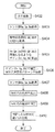
図4は、本実施形態1に係る画像表示装置の動作を説明するフローチャートである。尚、この処理を実行するプログラムはROM111に格納されており、CPU112の制御の下で実行される。
FIG. 4 is a flowchart for explaining the operation of the image display apparatus according to the first embodiment. Note that a program for executing this processing is stored in the
このフローチャートで示す処理は、電源投入か、もしくはスイッチ113の操作で開始される。まずS402で、パターン発生回路301から全面白色の画像データ(第1の画像)を発生させてスクリーン201に投影する。ここで、白色を投影するのは次の2つの理由がある。第1の理由は、白色を投影してこれを補正すればスクリーン201が着色している影響を排除して正しい白色が得られるからである。第2の理由は、白のような明るい光を投影すると、スクリーン201で反射する光は、照明光学系106の光源の影響を大きく受ける。このため、照明機器202からの照明光204の影響が小さくなり、照明光204の影響を受けずに壁色補正を行うことができるためである。
The processing shown in this flowchart is started by turning on the power or operating the
この時点では、まだ環境光補正のための3D-LUTを生成していないので3D-LUTは使用しない。従って、セレクタ306は乗算器303の出力信号を選択する。次にS403で、白色投影時のスクリーン201の色データRw,Gw,BwをそれぞれRセンサ116、Gセンサ117、Bセンサ118から取得する。次にS404に進み、ROM111に格納されている理想白色値である第1の色データR0,G0,B0をROM111から取得する。次にS405に進み、センサ部130から取得した第2の色データRw,Gw,Bwの比が、S404で取得した理想白色値R0,G0,B0の比と等しくなるようなゲインAr,Ag,Abを算出する。ここで、第1の色補正である壁色補正の演算により補正情報としてゲインAr,Ag,Abを算出し、乗算器303で乗算する例を挙げた。しかし本発明はこれに限定されるものではなく、オフセット値で各色の黒レベルを合わせた上でゲイン調整を行う等、他の方法であっても差し支えない。
At this point, since the 3D-LUT for correcting ambient light has not been generated, the 3D-LUT is not used. Accordingly, the
次にS406に進み、S405で算出したゲインAr,Ag,Abを乗算器303に送る。これと同時にパターン発生回路301は、照明光204の測定用パターンである全面グレー(第2の画像)を発生させてスクリーン201に投影する。ここで、白色画像からグレー画像の投影に変えるのは、照明光学系106の光源の影響を小さくすることで、スクリーン201で反射する照明光204を正確に測定するためである。またこのとき、投影画像にゲインAr,Ag,Abで壁色補正を実施しているので、スクリーン201の着色の影響を排除している。次にS407に進み、壁色補正を施したスクリーン201の色データRe、Ge,BeをそれぞれRセンサ116、Gセンサ117、Bセンサ118から取得する。
In step S406, the gains Ar, Ag, and Ab calculated in step S405 are sent to the multiplier 303. At the same time, the
次にS408に進み、S407で取得した色データRe、Ge,Beを式(1)(2)に代入して照明光204の色度を算出する。
In step S408, the chromaticity of the
r=Re/(Re+Ge+Be) ...式(1)
g=Ge/(Re+Ge+Be) ...式(2)
ここで算出した色度の例を図8(B)の810に示す。
r = Re / (Re + Ge + Be) Formula (1)
g = Ge / (Re + Ge + Be) Equation (2)
An example of the chromaticity calculated here is shown at 810 in FIG.
次にS409に進み、S408で算出した色度を基に照明光204を推定する。ここでは予めROM111に、F1〜F12(蛍光灯)、A(白色光源)、D50(5000K)、D65(昼光)の15種の標準光源に関して、尤度を判定するためのrg色度における中心値並びに主成分情報が格納されている。CPU112は、この尤度判定用のデータを読み出す。なお、本実施例では、15種類の標準光源としたが、当然、これ以上でも、これ以下でもよい。
In step S409, the
図9(A)は、予めROM111に格納した標準光源の中心値のrg色度での分布を示す図である。
FIG. 9A is a diagram showing a distribution in rg chromaticity of the center value of the standard light source stored in the
また図9(B)は、主成分情報の一例としてA光源並びにF12光源の主成分情報を示す図である。図9(B)において、中心値を中心として直交する2軸が主成分を表し、楕円は所定の尤度となる軌跡を表している。CPU112は、S408で算出した照明光204の色度について15種の光源に総てに対し尤度を求め、最も尤度の高かった光源を照明光の種別であると判定する。例えばS408で算出した照明光の色度が図8(B)及び図9(B)の810であった場合、照明光の種別はF10光源であると推定される。
FIG. 9B is a diagram showing the principal component information of the A light source and the F12 light source as an example of the principal component information. In FIG. 9B, two axes perpendicular to the center value represent the main component, and the ellipse represents a trajectory having a predetermined likelihood. CPU112 calculates | requires likelihood with respect to all the 15 types of light sources about the chromaticity of the
続いてS410に進み、S409で判定した照明光の種別に従い、LUT演算回路114で環境光補正のための色補正情報である3D-LUTを生成するための第2の色補正のための演算を行う。このS410で行われる三次元ルックアップテーブル3D-LUTの作成処理は、図5のフローチャートに基づいて行われる。
Subsequently, the process proceeds to S410, and in accordance with the type of illumination light determined in S409, the
図5は、本実施形態1に係るLUT演算回路114による処理を説明するフローチャートである。尚、この処理はCPU112の指示を受けたLUT演算回路114で実行される。この処理に先立って、予めデスティネーション側プロファイルとして、F1〜F12及びA、D50,D65に相当する照明下、並びに無照明下においてスクリーン上の色を測定することで作成したプロファイルを16種準備してROM111に格納しておく。
FIG. 5 is a flowchart for explaining processing by the LUT
まずS502で、LUT格子点に相当するRGB値を1つ取得する。次にS503に進み、その取得したRGB値をソース側のデバイスモデルに基づいてXYZ値に変換する。尚、ソース側デバイスモデルには、sRGBやAdobeRGB等種々のモデルを適用できる。本実施形態1では、ソース側デバイスモデルの例としてsRGBを使用するが、本発明はこれに限定されるものではない。 First, in S502, one RGB value corresponding to the LUT lattice point is acquired. In step S503, the acquired RGB values are converted into XYZ values based on the device model on the source side. Various models such as sRGB and AdobeRGB can be applied to the source side device model. In the first embodiment, sRGB is used as an example of the source-side device model, but the present invention is not limited to this.
次にS504に進み、国際照明委員会(CIE)が発行したCIECAM02に基づいて、S503で算出したXYZ値をJCh値に変換する。次にS505に進み、ソース側色域とデスティネーション側色域とに基づき、デスティネーション色域内の色は変換せず、デスティネーション色域外の色は、距離最小のデスティネーション側色域表面に写像するように色域写像を施す。尚、ソース側色域とデスティネーション側色域は、この処理に先立って予め算出しておく。次にS506に進み、CIECAM02に基づいてS504で算出したJCh値をXYZ値に変換する。次にS507に進み、S506で算出したXYZ値をデスティネーション側のデバイスモデルに基づいてRGB値に変換する。尚、このS507で使用するデスティネーション側プロファイルは、先述の16種のプロファイルから選択されるものである。そしてS508で、LUT格子点の総てに対し変換RGB値を算出したかどうかを判断し、完了していればS509へ進み、完了していなければS502へ戻る。S509では、変換用の3D-LUTをテーブル格納部110に保存して、この処理を終了する。
In step S504, the XYZ value calculated in step S503 is converted into a JCh value based on CIECAM02 issued by the International Commission on Illumination (CIE). In step S505, based on the source-side gamut and destination-side gamut, colors in the destination gamut are not converted, and colors outside the destination gamut are mapped to the surface of the destination-side gamut with the smallest distance. Color gamut mapping is performed as follows. Note that the source side gamut and the destination side gamut are calculated in advance prior to this processing. In step S506, the JCh value calculated in step S504 based on CIECAM02 is converted into an XYZ value. In step S507, the XYZ values calculated in step S506 are converted into RGB values based on the destination-side device model. The destination profile used in S507 is selected from the 16 types of profiles described above. In step S508, it is determined whether converted RGB values have been calculated for all of the LUT lattice points. If completed, the process proceeds to step S509. If not completed, the process returns to step S502. In S509, the 3D-LUT for conversion is saved in the
図6は、本実施形態1に係る色補正用3D-LUTを説明する図である。 FIG. 6 is a diagram illustrating the color correction 3D-LUT according to the first embodiment.
RGB色空間における格子点の色座標データと、その格子点のRGB座標値に対応付けられた格子点データであるRGBの値の組とを表している。図6では、RGBデータが10ビットで、RGB軸それぞれに対して8等分した箇所に格子点を有する例を示しているが、信号のビット数と格子点の数はこれに限ったものではない。 It represents the color coordinate data of a grid point in the RGB color space and a set of RGB values that are grid point data associated with the RGB coordinate value of the grid point. FIG. 6 shows an example in which the RGB data is 10 bits and has grid points at 8 equal parts for each of the RGB axes. However, the number of signal bits and the number of grid points are not limited to this. Absent.
図5のフローチャートでは、(R,G,B)=(0,0,0)から、(R,G,B)=(1023,1023,1023)までの各格子点について、S502からS507までの処理を行い、環境光補正のための3D-LUTを生成する。尚、格子点以外の変換RGB値は補間処理によって生成する。 In the flowchart of FIG. 5, for each lattice point from (R, G, B) = (0, 0, 0) to (R, G, B) = (1023, 1023, 1023), S502 to S507 are performed. Processing is performed to generate a 3D-LUT for ambient light correction. The converted RGB values other than the grid points are generated by interpolation processing.
本実施形態1では、LUT演算回路114を具備し、CPU112の指示を受けてハードウェアで3D-LUTを生成する例で説明した。しかし、3D-LUTの生成方法はこれに限ったものではなく、LUT演算回路114を具備せずに、ソフトウェアに従ってCPU112での演算で生成しても差し支えない。ハード、ソフトウェアいずれの場合でも、図4及び図5のフローチャートに基づいて動作する点でなんら変わりは無い。
In the first embodiment, an example in which the LUT
また本実施形態1では、判定した照明光の種別に従い、LUT演算回路114で環境光補正のための3D-LUTを生成している。しかし本発明はこれに限らず、ROM111に予め各照明光に対応する3D-LUTを用意しておき、図4のS410で判定した照明光に対応する3D-LUTを選択してもよい。
In the first embodiment, the
以上説明したように本実施形態1では、画像表示装置において、まずセンサで投影面の色を測定してスクリーン色補正(壁色補正)を行って投影し、その状態で、再びセンサで投影面の色を測定して照明光(環境光)を推定する。これによりスクリーンが着色している場合にも照明光を正確に推定し、更に、推定した照明光から照明光補正のための3D-LUTを正確に生成することができる。 As described above, in the first embodiment, in the image display apparatus, first, the color of the projection plane is measured by the sensor, the screen color correction (wall color correction) is performed, and the projection is performed. The illumination light (environment light) is estimated by measuring the color. This makes it possible to accurately estimate the illumination light even when the screen is colored, and to accurately generate a 3D-LUT for correcting the illumination light from the estimated illumination light.
また、3D-LUT生成の際、壁色補正の機能を含まず、照明光の補正のみを行うテーブルを生成すればよいので演算時間を短縮できる。更に、もし投影中に照明光の種類や状態が変わっても、壁色補正は前の状態の照明光下で完了しているので、迅速に照明光を推定して照明光補正のための3D-LUTを正確に生成することができるという効果がある。 Further, when generating the 3D-LUT, it is only necessary to generate a table that does not include the wall color correction function and only corrects the illumination light, so that the calculation time can be shortened. In addition, even if the type or state of the illumination light changes during projection, the wall color correction is completed under the illumination light in the previous state. -There is an effect that the LUT can be generated accurately.
[実施形態2]
次に本発明の実施形態2を図7を参照して説明する。尚、実施形態2に係る画像表示装置の構成は前述の実施形態1に係る画像表示装置の構成(図1)と同じであるため、その説明を省略する。前述の実施形態1では、ゲインの調整で壁色補正を行っていたのに対し、本実施形態2では、一次元ルックアップテーブル(1D-LUT)で壁色補正を行う点で異なる。この1D-LUTの生成は、基本となる1D-LUTをROM111に格納しておき、壁色補正に伴う特性の変更をLUT演算回路114で行ってテーブル格納部110に保持してもよい。また或いは、何も無い状態からLUT演算回路114で生成してテーブル格納部110に送ってもよい。このとき、環境光補正のための3D-LUTとは別のテーブル格納部110の領域に1D-LUTを格納する。
[Embodiment 2]
Next, a second embodiment of the present invention will be described with reference to FIG. The configuration of the image display device according to the second embodiment is the same as the configuration of the image display device according to the first embodiment (FIG. 1), and a description thereof will be omitted. In the first embodiment described above, the wall color correction is performed by adjusting the gain. In the second embodiment, the wall color correction is performed using a one-dimensional lookup table (1D-LUT). The 1D-LUT may be generated by storing the basic 1D-LUT in the
この1D-LUTの生成もしくは変更は、図4のフローチャートのS405で行われる。ここでは、RGBそれぞれの1D-LUTの出力値の比がR0:G0:B0になるようにする。通常、1D-LUTはガンマ補正を行うためのものである。このガンマ補正は、前述の実施形態1の液晶表示素子駆動回路105で行うVTガンマ補正で置き換えてもよいし、γ=2.2のようなガンマ補正でもよい。
The generation or modification of the 1D-LUT is performed in S405 of the flowchart of FIG. Here, the ratio of the output values of 1D-LUT for RGB is set to R0: G0: B0. Usually, 1D-LUT is for performing gamma correction. This gamma correction may be replaced by VT gamma correction performed by the liquid crystal display
図7は、本実施形態2に係る色補正回路104の構成を示すブロック図である。
FIG. 7 is a block diagram showing the configuration of the
解像度変換部103の出力がセレクタ302に入力される。一方、投影面を測定するためのキャリブレーションパターンを発生するパターン発生回路301の出力もセレクタ302に入力される。セレクタ302は、CPU112の指示に従って、スクリーン201の色を測定するためのキャリブレーションパターンを使用する際はパターン発生回路301の出力を選択し、通常の画像の投影時は解像度変換部103の出力を選択する。セレクタ302の出力は、セレクタ310とアドレス送出回路308に送られる。アドレス送出回路308は、セレクタ302の出力信号をテーブル格納部110のアドレスに変換し、データバス131を通じてテーブル格納部110に送る。テーブル格納部110は、入力したアドレスに書き込まれたデータを読み出し、データバス131を介してデータ格納部309に送る。データ格納部309は、テーブル格納部110からのデータから、セレクタ302の出力信号に所定の補正を施したものに対応する信号値を抽出してセレクタ310に送る。尚、アドレス送出回路308とデータ格納部309とは、1D-LUTに関するアドレスとデータを授受する。セレクタ310はCPU112の指示に従って、1D-LUTによる壁色補正を行うときはデータ格納部309の出力信号を選択し、1D-LUTによる壁色補正を行わないときはセレクタ302の出力信号を選択する。
The output of the
セレクタ310の出力は、セレクタ306とアドレス送出回路304とに送られる。アドレス送出回路304は、セレクタ310の出力信号をテーブル格納部110のアドレスに変換して、データバス131を通じてテーブル格納部110に送る。テーブル格納部110は、入力したアドレスに書き込まれたデータを読み出し、データバス131を通じてデータ格納部305に送る。データ格納部305は、テーブル格納部110からのデータから、セレクタ310の出力信号に所定の補正を施したものに対応する信号値を抽出してセレクタ306に送る。尚、アドレス送出回路304とデータ格納部305とは、3D-LUTに関するアドレスとデータを授受する。セレクタ306は、CPU112の指示に従って、3D-LUTによる環境光補正を行うときはデータ格納部305の出力を選択し、環境光補正を行なわないときは、セレクタ310の出力信号を選択する。
The output of the
以上説明したように本実施形態2によれば、まずセンサで投影面の色を測定して1D-LUTでスクリーン色補正(壁色補正)を行って投影し、その状態で、再びセンサで投影面の色を測定して照明光(環境光)を推定する。これにより、スクリーンが着色している場合にも照明光を正確に推定でき、更に、推定した照明光から照明光補正のための3D-LUTを正確に生成することができる。 As described above, according to the second embodiment, first, the color of the projection surface is measured by the sensor, the screen color correction (wall color correction) is performed by the 1D-LUT, and then the projection is performed. The surface color is measured to estimate the illumination light (ambient light). Thereby, even when the screen is colored, the illumination light can be accurately estimated, and further, a 3D-LUT for illumination light correction can be accurately generated from the estimated illumination light.
また3D-LUT生成の際、壁色補正の機能を含まず、照明光補正のみを行うテーブルを生成すればよいので演算時間を短縮できる。更に、投影中に照明光の種類や明るさが変わった場合でも、壁色補正は前の状態の照明光下で完了しているので、迅速に照明光を推定して照明光補正のための3D-LUTを正確に生成することができる。
(その他の実施例)
また、本発明は、以下の処理を実行することによっても実現される。即ち、上述した実施形態の機能を実現するソフトウェア(プログラム)を、ネットワーク又は各種記憶媒体を介してシステム或いは装置に供給し、そのシステム或いは装置のコンピュータ(またはCPUやMPU等)がプログラムを読み出して実行する処理である。
Further, when generating the 3D-LUT, it is only necessary to generate a table that does not include the wall color correction function and performs only the illumination light correction, so that the calculation time can be shortened. Furthermore, even if the type or brightness of the illumination light changes during projection, the wall color correction is completed under the illumination light in the previous state, so the illumination light can be quickly estimated to correct the illumination light. 3D-LUT can be generated accurately.
(Other examples)
The present invention can also be realized by executing the following processing. That is, software (program) that realizes the functions of the above-described embodiments is supplied to a system or apparatus via a network or various storage media, and a computer (or CPU, MPU, or the like) of the system or apparatus reads the program. It is a process to be executed.
Claims (14)
前記取得した画像データを補正する第1の補正手段と、
前記第1の補正手段により補正された画像データをさらに補正する第2の補正手段と、
画像データに基づく画像を投影面に投影する投影手段と、
前記投影面上の色を測定する測色手段と、
制御手段とを有し、
前記制御手段は、前記第1の補正手段及び前記第2の補正手段により補正されない第1の所定画像を投影するように前記投影手段を制御し、前記第1の所定画像が投影された前記投影面上の色を測定する第1の測定を実行するように前記測色手段を制御し、
前記制御手段は、第1の測定の測定結果のRGB比率が、前記第1の所定画像のRGB比率と近づくパラメータで、第2の所定画像を補正するように前記第1の補正手段を制御し、前記第1の補正手段により補正され、前記第2の補正手段により補正されない前記第2の所定画像を投影するように前記投影手段を制御し、前記第2の所定画像が投影された前記投影面上の色を測定する第2の測定を実行するように前記測色手段を制御し、
前記制御手段は、前記第2の測定の測定結果に応じて、前記第2の補正手段に入力された画像データのRGB値の変換テーブルを決定することを特徴とする画像表示装置。 Acquisition means for acquiring image data;
First correction means for correcting the acquired image data;
Second correction means for further correcting the image data corrected by the first correction means;
Projection means for projecting an image based on the image data onto a projection plane;
A colorimetric means for measuring a color on the projection plane;
Control means,
The control unit controls the projection unit to project a first predetermined image that is not corrected by the first correction unit and the second correction unit, and the projection on which the first predetermined image is projected. Controlling the colorimetric means to perform a first measurement to measure the color on the surface;
The control unit controls the first correction unit to correct the second predetermined image with a parameter in which the RGB ratio of the measurement result of the first measurement approaches the RGB ratio of the first predetermined image. The projection unit that controls the projection unit to project the second predetermined image that is corrected by the first correction unit and not corrected by the second correction unit, and the second predetermined image is projected. Controlling the colorimetric means to perform a second measurement for measuring the color on the surface;
The image display apparatus according to claim 1, wherein the control unit determines a conversion table of RGB values of the image data input to the second correction unit according to the measurement result of the second measurement.
前記制御手段は、前記補正後の画像データに基づく画像を前記投影面上に投影するように、前記投影手段を制御することを特徴とする請求項1乃至6のいずれか1項に記載の画像表示装置。 The control means causes the first correction means and the second correction means to correct the image data acquired by the acquisition means,
The image according to any one of claims 1 to 6 , wherein the control unit controls the projection unit to project an image based on the corrected image data onto the projection plane. Display device.
取得手段が、画像データを取得する取得工程と、
第1の補正手段が、前記取得した画像データを補正する第1の補正工程と、
第2の補正手段が、前記第1の補正工程で補正された画像データをさらに補正する第2の補正工程と、
投影手段が、画像データに基づく画像を投影面に投影する投影工程と、
測色手段が、前記投影面上の色を測定する測色工程と、
制御手段が、(i)前記第1の補正工程及び前記第2の補正工程で補正されない第1の所定画像を投影するように前記投影工程を制御し、前記第1の所定画像が投影された前記投影面上の色を測定する第1の測定を実行するように前記測色工程を制御し、
(ii)前記第1の測定の測定結果のRGB比率が、前記第1の所定画像のRGB比率と近づくパラメータで、第2の所定画像を補正するように前記第1の補正工程を制御し、前記第1の補正工程で補正され、前記第2の補正工程で補正されない前記第2の所定画像を投影するように前記投影工程を制御し、前記第2の所定画像が投影された前記投影面上の色を測定する第2の測定を実行するように前記測色工程を制御し、
(iii)前記第2の測定の測定結果に応じて、前記第2の補正工程に入力された画像データのRGB値の変換テーブルを決定する制御工程と、
を有することを特徴とする画像表示装置の制御方法。 A control method of an image display device for displaying an image by a projection type projector,
An acquisition step in which the acquisition means acquires image data;
A first correction unit that corrects the acquired image data;
A second correction step, wherein the second correction means further corrects the image data corrected in the first correction step;
A projecting step of projecting an image based on the image data onto a projection surface;
A color measurement step in which a color measurement means measures a color on the projection surface;
The control means controls (i) the projection step so as to project the first predetermined image that is not corrected in the first correction step and the second correction step, and the first predetermined image is projected. Controlling the colorimetry process to perform a first measurement for measuring a color on the projection surface;
(Ii) controlling the first correction step so as to correct the second predetermined image with a parameter in which the RGB ratio of the measurement result of the first measurement approaches the RGB ratio of the first predetermined image; The projection surface on which the second predetermined image is projected by controlling the projection step so as to project the second predetermined image that is corrected in the first correction step and not corrected in the second correction step. Controlling the colorimetric process to perform a second measurement to measure the upper color;
(Iii) a control step of determining an RGB value conversion table of the image data input to the second correction step according to the measurement result of the second measurement;
A control method for an image display device, comprising:
前記制御工程は、前記補正後の画像データに基づく画像を前記投影面上に投影するように、前記投影工程を制御することを特徴とする請求項8乃至13のいずれか1項に記載の制御方法。 The control step corrects the image data acquired in the acquisition step in the first correction step and the second correction step,
The control according to any one of claims 8 to 13 , wherein the control step controls the projection step so that an image based on the corrected image data is projected onto the projection plane. Method.
Priority Applications (2)
| Application Number | Priority Date | Filing Date | Title |
|---|---|---|---|
| JP2009157313A JP5430254B2 (en) | 2009-07-01 | 2009-07-01 | Image display apparatus and control method thereof |
| US12/818,567 US8870393B2 (en) | 2009-07-01 | 2010-06-18 | Image projection apparatus and method of controlling the same including determining a correction table for correcting RGB values of image data |
Applications Claiming Priority (1)
| Application Number | Priority Date | Filing Date | Title |
|---|---|---|---|
| JP2009157313A JP5430254B2 (en) | 2009-07-01 | 2009-07-01 | Image display apparatus and control method thereof |
Publications (3)
| Publication Number | Publication Date |
|---|---|
| JP2011013443A JP2011013443A (en) | 2011-01-20 |
| JP2011013443A5 JP2011013443A5 (en) | 2012-08-16 |
| JP5430254B2 true JP5430254B2 (en) | 2014-02-26 |
Family
ID=43412455
Family Applications (1)
| Application Number | Title | Priority Date | Filing Date |
|---|---|---|---|
| JP2009157313A Expired - Fee Related JP5430254B2 (en) | 2009-07-01 | 2009-07-01 | Image display apparatus and control method thereof |
Country Status (2)
| Country | Link |
|---|---|
| US (1) | US8870393B2 (en) |
| JP (1) | JP5430254B2 (en) |
Families Citing this family (20)
| Publication number | Priority date | Publication date | Assignee | Title |
|---|---|---|---|---|
| JP5565139B2 (en) * | 2010-06-28 | 2014-08-06 | セイコーエプソン株式会社 | Image processing apparatus, projection display apparatus, and image processing method |
| KR101783259B1 (en) * | 2010-12-31 | 2017-10-10 | 삼성디스플레이 주식회사 | Method for compensating data, compensating apparatus for performing the method and display device having the compensating apparatus |
| WO2012119215A1 (en) | 2011-03-04 | 2012-09-13 | Eski Inc. | Devices and methods for providing a distributed manifestation in an environment |
| US20130113975A1 (en) * | 2011-11-04 | 2013-05-09 | Peter Gabris | Projector Image Correction Method and System |
| US9377673B2 (en) * | 2012-07-20 | 2016-06-28 | Prysm, Inc. | Closed loop verification of rendered content |
| CN104104891B (en) * | 2013-04-10 | 2018-08-10 | 中强光电股份有限公司 | Projection arrangement and its projection auto-correction method |
| JP6228469B2 (en) * | 2014-01-20 | 2017-11-08 | 株式会社東芝 | Image processing apparatus, image processing method, and image projection apparatus |
| TWI549516B (en) * | 2014-10-03 | 2016-09-11 | 宏碁股份有限公司 | Electronic device and method for projecting screen adjustment |
| JP6729384B2 (en) * | 2015-02-26 | 2020-07-22 | ソニー株式会社 | Electronics |
| JP6554887B2 (en) * | 2015-04-14 | 2019-08-07 | 富士ゼロックス株式会社 | Image generating apparatus, evaluation system, and program |
| CN106610314B (en) * | 2015-12-31 | 2019-02-22 | 北京一数科技有限公司 | A kind of method for detecting color and device |
| TWI653563B (en) * | 2016-05-24 | 2019-03-11 | 仁寶電腦工業股份有限公司 | Projection touch image selection method |
| JP2019536494A (en) | 2016-09-07 | 2019-12-19 | エスキー インコーポレイテッドESKI Inc. | Distributed expression projection system and related methods |
| JP2018092007A (en) * | 2016-12-02 | 2018-06-14 | キヤノン株式会社 | Image processor and image processing method, program, and storage medium |
| CN109104596B (en) | 2017-06-21 | 2021-02-26 | 中强光电股份有限公司 | Projection system and correction method of display image |
| EP3834096A4 (en) * | 2018-08-08 | 2022-04-20 | IP Investment Holdings, LLC | System and method for operation in an augmented reality display device |
| JP7172294B2 (en) * | 2018-08-30 | 2022-11-16 | セイコーエプソン株式会社 | Projector, color correction system, and projector control method |
| EP4010894A1 (en) | 2019-12-11 | 2022-06-15 | Google LLC | Color calibration of display modules using a reduced number of display characteristic measurements |
| CN112738489B (en) * | 2020-12-23 | 2021-12-07 | 深圳市火乐科技发展有限公司 | Projection equipment control method, device, medium and electronic equipment |
| US11842678B2 (en) | 2021-10-12 | 2023-12-12 | Google Llc | High-brightness mode on an OLED display |
Family Cites Families (19)
| Publication number | Priority date | Publication date | Assignee | Title |
|---|---|---|---|---|
| JPH04136925A (en) * | 1990-09-28 | 1992-05-11 | Sharp Corp | Liquid crystal projector |
| JP3719499B2 (en) * | 2000-09-13 | 2005-11-24 | セイコーエプソン株式会社 | Correction curve generation method, image processing method, image display apparatus, and recording medium |
| JP2002262304A (en) * | 2001-03-06 | 2002-09-13 | Seiko Epson Corp | Image display device, image processing method and program |
| JP3729252B2 (en) * | 2001-03-26 | 2005-12-21 | セイコーエプソン株式会社 | Image processing system, program, and information storage medium |
| JP3800063B2 (en) * | 2001-10-19 | 2006-07-19 | コニカミノルタフォトイメージング株式会社 | Image display system |
| JP2003323610A (en) * | 2002-03-01 | 2003-11-14 | Nec Corp | Color correcting method and device, for projector |
| JP3755593B2 (en) * | 2002-03-26 | 2006-03-15 | セイコーエプソン株式会社 | Projection-type image display system, projector, program, information storage medium, and image processing method |
| JP3514257B2 (en) * | 2002-05-20 | 2004-03-31 | セイコーエプソン株式会社 | Image processing system, projector, image processing method, program, and information storage medium |
| JP3731663B2 (en) * | 2002-12-04 | 2006-01-05 | セイコーエプソン株式会社 | Image processing system, projector, and image processing method |
| US7184054B2 (en) * | 2003-01-21 | 2007-02-27 | Hewlett-Packard Development Company, L.P. | Correction of a projected image based on a reflected image |
| JP3690402B2 (en) * | 2003-03-28 | 2005-08-31 | セイコーエプソン株式会社 | Image processing system, projector, program, information storage medium, and image processing method |
| JP3620537B2 (en) * | 2003-05-02 | 2005-02-16 | セイコーエプソン株式会社 | Image processing system, projector, program, information storage medium, and image processing method |
| TWI249959B (en) * | 2003-05-16 | 2006-02-21 | Seiko Epson Corp | Image processing system, projector, information memorizing medium and image processing method |
| JP4085283B2 (en) * | 2005-02-14 | 2008-05-14 | セイコーエプソン株式会社 | Image processing system, projector, program, information storage medium, and image processing method |
| JP4126564B2 (en) * | 2005-02-14 | 2008-07-30 | セイコーエプソン株式会社 | Image processing system, projector, program, information storage medium, and image processing method |
| JP4432818B2 (en) * | 2005-04-01 | 2010-03-17 | セイコーエプソン株式会社 | Image display device, image display method, and image display program |
| JP2007166271A (en) * | 2005-12-14 | 2007-06-28 | Seiko Epson Corp | Projection system and projector |
| CN100594421C (en) * | 2007-12-03 | 2010-03-17 | 佛山普立华科技有限公司 | Color optimization system and method of digital light processing projecting machine |
| JP5655265B2 (en) * | 2008-11-04 | 2015-01-21 | セイコーエプソン株式会社 | Projector, image quality adjustment method, image quality adjustment program, and recording medium |
-
2009
- 2009-07-01 JP JP2009157313A patent/JP5430254B2/en not_active Expired - Fee Related
-
2010
- 2010-06-18 US US12/818,567 patent/US8870393B2/en not_active Expired - Fee Related
Also Published As
| Publication number | Publication date |
|---|---|
| US20110001881A1 (en) | 2011-01-06 |
| JP2011013443A (en) | 2011-01-20 |
| US8870393B2 (en) | 2014-10-28 |
Similar Documents
| Publication | Publication Date | Title |
|---|---|---|
| JP5430254B2 (en) | Image display apparatus and control method thereof | |
| JP4445693B2 (en) | Projector projection surface color correction method, projector projection surface color correction system, and projector projection surface color correction program | |
| JP3719411B2 (en) | Image display system, projector, program, information storage medium, and image processing method | |
| JP3514257B2 (en) | Image processing system, projector, image processing method, program, and information storage medium | |
| JP3707350B2 (en) | Image display system, projector, image processing method, and information storage medium | |
| US20070110304A1 (en) | Projector color correcting method | |
| JP4311411B2 (en) | Color conversion table generation device, display device, color conversion table generation method, and display device manufacturing method | |
| US8534843B2 (en) | Image display apparatus, information processing apparatus, and methods of controlling the same | |
| JPWO2003001499A1 (en) | Image display system, projector, image processing method, and information storage medium | |
| WO2003079327A1 (en) | Image display apparatus, image processing method, program, and recording medium | |
| JP2001128021A (en) | Picture processor, computer readable storage medium and picture processing method | |
| JP4830359B2 (en) | Color monitor calibration method, color monitor calibration program, color monitor color management system, etc. | |
| JP3635673B2 (en) | Image processing method and image processing apparatus | |
| JP2012248910A (en) | Color correction method of projection display device | |
| JP2006270336A (en) | Display device and display method | |
| JP4530200B2 (en) | Method and apparatus for color monitor calibration and / or profile creation | |
| JP2010217645A (en) | Method, device and program of making correction value of image display device | |
| JP2014072855A (en) | Image display apparatus | |
| JP5822575B2 (en) | Image projection apparatus, control method for image projection apparatus, and program | |
| JP2007259472A (en) | Method, system and program for correcting projection plane color of projector | |
| JP2010217644A (en) | Method, device and program of making correction value of image display device | |
| JP5517594B2 (en) | Image display device and image display method | |
| JP2006033881A (en) | Image display device, image processing method and program | |
| JP2012248911A (en) | Image display device | |
| JP5058532B2 (en) | Image display system and image display method |
Legal Events
| Date | Code | Title | Description |
|---|---|---|---|
| A521 | Request for written amendment filed |
Free format text: JAPANESE INTERMEDIATE CODE: A523 Effective date: 20120629 |
|
| A621 | Written request for application examination |
Free format text: JAPANESE INTERMEDIATE CODE: A621 Effective date: 20120629 |
|
| A977 | Report on retrieval |
Free format text: JAPANESE INTERMEDIATE CODE: A971007 Effective date: 20130828 |
|
| A131 | Notification of reasons for refusal |
Free format text: JAPANESE INTERMEDIATE CODE: A131 Effective date: 20130906 |
|
| A521 | Request for written amendment filed |
Free format text: JAPANESE INTERMEDIATE CODE: A523 Effective date: 20130930 |
|
| TRDD | Decision of grant or rejection written | ||
| A01 | Written decision to grant a patent or to grant a registration (utility model) |
Free format text: JAPANESE INTERMEDIATE CODE: A01 Effective date: 20131105 |
|
| A61 | First payment of annual fees (during grant procedure) |
Free format text: JAPANESE INTERMEDIATE CODE: A61 Effective date: 20131203 |
|
| R151 | Written notification of patent or utility model registration |
Ref document number: 5430254 Country of ref document: JP Free format text: JAPANESE INTERMEDIATE CODE: R151 |
|
| LAPS | Cancellation because of no payment of annual fees |