JP5426268B2 - Mobile X-ray equipment - Google Patents
Mobile X-ray equipment Download PDFInfo
- Publication number
- JP5426268B2 JP5426268B2 JP2009180331A JP2009180331A JP5426268B2 JP 5426268 B2 JP5426268 B2 JP 5426268B2 JP 2009180331 A JP2009180331 A JP 2009180331A JP 2009180331 A JP2009180331 A JP 2009180331A JP 5426268 B2 JP5426268 B2 JP 5426268B2
- Authority
- JP
- Japan
- Prior art keywords
- handle
- height
- operation panel
- traveling
- ray
- Prior art date
- Legal status (The legal status is an assumption and is not a legal conclusion. Google has not performed a legal analysis and makes no representation as to the accuracy of the status listed.)
- Expired - Fee Related
Links
- 230000007246 mechanism Effects 0.000 claims description 81
- 238000003384 imaging method Methods 0.000 claims description 66
- 238000010586 diagram Methods 0.000 description 9
- 230000008859 change Effects 0.000 description 4
- 230000008602 contraction Effects 0.000 description 4
- 125000002066 L-histidyl group Chemical group [H]N1C([H])=NC(C([H])([H])[C@](C(=O)[*])([H])N([H])[H])=C1[H] 0.000 description 3
- 238000001514 detection method Methods 0.000 description 2
- 230000000694 effects Effects 0.000 description 2
- 210000000245 forearm Anatomy 0.000 description 2
- 238000000034 method Methods 0.000 description 2
- 230000004048 modification Effects 0.000 description 1
- 238000012986 modification Methods 0.000 description 1
- 230000001151 other effect Effects 0.000 description 1
- 238000003825 pressing Methods 0.000 description 1
- 230000008569 process Effects 0.000 description 1
- 230000005855 radiation Effects 0.000 description 1
- 230000009467 reduction Effects 0.000 description 1
- 230000004044 response Effects 0.000 description 1
Images


Description
本発明は、移動型X線撮影装置に係わり、特に、病室等へ移動して患者のX線撮影を行うための移動型X線撮影装置に関する。 The present invention relates to a mobile X-ray imaging apparatus, and more particularly to a mobile X-ray imaging apparatus for moving to a hospital room or the like to perform X-ray imaging of a patient.
病院の入院患者には,病状が重く、X線検査室へ行ってX線検査を受けることができない者もいる。このような患者のX線検査を行う装置に移動型X線撮影装置がある。すなわち、移動型X線撮影装置は、X線撮影装置を移動台車へ搭載したもので、移動台車によってX線撮影装置を保管場所から患者が寝ているベッドサイドへ移動してX線撮影を行うものである。そして、このような移動型X線撮影装置は、電動式移動台車に搭載された筐体部に固定された走行用ハンドルを操作することで病室へ移動する。 Some hospitalized patients have severe medical conditions and cannot go to the X-ray laboratory and receive an X-ray examination. There is a mobile X-ray imaging apparatus as an apparatus for performing such an X-ray examination of a patient. That is, the mobile X-ray imaging apparatus includes an X-ray imaging apparatus mounted on a moving carriage, and the X-ray imaging apparatus performs X-ray imaging by moving the X-ray imaging apparatus from the storage location to the bedside where the patient is sleeping. Is. Such a mobile X-ray imaging apparatus moves to a hospital room by operating a traveling handle fixed to a casing unit mounted on an electric mobile carriage.
このような走行用ハンドルを備える移動型X線撮影装置には、特許文献1に記載の移動型X線装置のように、台車の前部側と後部側とにそれぞれ走行用ハンドルを設けたものが記載されている。この特許文献1に記載の移動型X線撮影装置では、X線発生部の不使用時である移動時等にX線発生部を装置本体に固定するロック機構に連動して、走行用ハンドルを上下動させる構成となっている。 In such a mobile X-ray imaging apparatus provided with a traveling handle, a traveling handle is provided on each of the front side and the rear side of the carriage as in the mobile X-ray apparatus described in Patent Document 1. Is described. In the mobile X-ray imaging apparatus described in Patent Document 1, the traveling handle is interlocked with a lock mechanism that fixes the X-ray generation unit to the apparatus body when the X-ray generation unit is not used. It is configured to move up and down.
台車の移動速度の制御信号を検出する手段は、水平方向のハンドル移動量を検出するセンサを利用しているため、操作者が効率的に台車を移動するためには、ハンドルへ水平方向に力を作用させることが必要である。つまり、操作者の前腕が水平に保たれる高さに操作ハンドルが位置することが好ましい。しかし、操作者の身長には個人差があるため、特定の操作者にとってはハンドルの取り付け高さが合っていても、別の操作者にとってはその高さが合わないということが懸念されている。すなわち、従来の移動型X線撮影装置では、平均的な伸長に基づいて走行用ハンドルの高さが決定されているために、この平均身長よりも高い又は低い操作者にとっては、走行用ハンドルの取り付け高さが合わないためである。 The means for detecting the control signal for the movement speed of the carriage uses a sensor for detecting the amount of movement of the handle in the horizontal direction. Therefore, in order for the operator to move the carriage efficiently, a force is applied to the handle in the horizontal direction. It is necessary to act. That is, it is preferable that the operation handle is positioned at a height at which the operator's forearm is kept horizontal. However, because the height of the operator varies from person to person, there is a concern that even if the height of the handle is appropriate for a specific operator, the height may not be appropriate for another operator. . That is, in the conventional mobile X-ray imaging apparatus, since the height of the traveling handle is determined based on the average extension, for the operator who is higher or lower than the average height, This is because the mounting height does not match.
この場合、走行用ハンドルの取り付け高さが高いと感じる操作者にとっては押す力が水平よりも上方へ向き、また走行用ハンドルの取り付け高さが低いと感じる操作者にとっては押す力が水平よりも下方へ向くため、走行用ハンドルの高さが合っている操作者に比べ、大きな押す力を必要とする。 In this case, for the operator who feels that the mounting height of the traveling handle is high, the pushing force is directed upward from the horizontal, and for the operator who feels that the mounting height of the traveling handle is low, the pushing force is higher than the horizontal. Since it faces downwards, it requires a larger pressing force than an operator whose traveling handle is at the correct height.
さらには、身長が高い操作者にとっては、腰を曲げた姿勢で走行用ハンドルを操作しなければならず、身体的に大きな負担となっている。 Furthermore, an operator having a high height must operate the traveling handle in a posture in which his / her waist is bent, which is a heavy physical burden.
本発明はこれらの問題点に鑑みてなされたものであり、本発明の目的は、操作者の身長が異なる場合における操作性を改善することが可能な移動型X線撮影装置を提供することにある。 The present invention has been made in view of these problems, and an object of the present invention is to provide a mobile X-ray imaging apparatus capable of improving operability when the height of the operator is different. is there.
(1)前記課題を解決すべく、被検体にX線を照射するX線発生部を有するX線撮影部と、前記X線撮影部を搭載する台車と、前記台車の側面且つ後部に設置され前記台車の走行を制御する走行用ハンドルと、を備えた移動型X線撮影装置であって、前記走行用ハンドルの床面からの高さを変更するハンドル高さ調整機構と、前記X線の照射条件を設定する操作用パネルと、前記ハンドル高さ調整機構と前記操作用パネルを支持し、当該一辺を中心とし回転移動することで前記ハンドル高さ調整機構と前記操作用パネルを連動させながら上下方向へ移動させて床面からの高さを変更するフレームを有する操作パネル面調整機構と、前記走行用ハンドル、又は前記走行用ハンドルと前記操作用パネルの高さを設定する設定値入力手段と、前記設定値入力手段によって設定された設定値に基づいて前記ハンドル高さ調整機構及び/又は前記操作パネル面調整機構を用いて前記走行用ハンドル、又は前記走行用ハンドルと前記操作用パネルの高さを移動させる制御手段と、を備える移動型X線撮影装置である。
(1) In order to solve the above-mentioned problem, the X-ray imaging unit having an X-ray generation unit that irradiates the subject with X-rays, a cart on which the X-ray imaging unit is mounted, a side surface and a rear part of the cart. A traveling X-ray imaging apparatus comprising: a traveling handle for controlling traveling of the carriage; a handle height adjusting mechanism for changing a height of the traveling handle from a floor surface ; An operation panel for setting irradiation conditions, the handle height adjustment mechanism and the operation panel are supported, and the handle height adjustment mechanism and the operation panel are interlocked by rotating around the one side. An operation panel surface adjustment mechanism having a frame that moves in the vertical direction to change the height from the floor surface, and a set value input means for setting the travel handle, or the height of the travel handle and the operation panel And the above Based on the set value set by the value input means, the handle height adjusting mechanism and / or the operation panel surface adjusting mechanism is used to move the traveling handle or the height of the traveling handle and the operation panel. A mobile X-ray imaging apparatus.
本発明によれば、操作者の身長に大きな違いがあっても大幅に操作性を改善することができる。 According to the present invention, the operability can be greatly improved even if there is a large difference in the height of the operator.
本発明のその他の効果については、明細書全体の記載から明らかにされる。 Other effects of the present invention will become apparent from the description of the entire specification.
以下、本発明が適用された実施形態について、図面を用いて説明する。ただし、以下の説明において、同一構成要素には同一符号を付し繰り返しの説明は省略する。 Embodiments to which the present invention is applied will be described below with reference to the drawings. However, in the following description, the same components are denoted by the same reference numerals, and repeated description is omitted.
〈実施形態1〉
〈全体構成〉
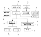
図1は本発明の実施形態1の移動型X線撮影装置の全体構成を説明するための図であり、以下、図1に基づいて、実施形態1の移動型X線撮影装置の全体構成を説明する。ただし、実施形態1の移動型X線撮影装置は走行用ハンドルの高さ調整機構を除く他の構成は、従来のX線装置と同様の構成となる。従って、以下の説明では、実施形態1の高さ調整機構及びその制御部について、詳細に説明する。
<Embodiment 1>
<overall structure>
FIG. 1 is a diagram for explaining the overall configuration of a mobile X-ray imaging apparatus according to Embodiment 1 of the present invention. Hereinafter, the overall configuration of the mobile X-ray imaging apparatus according to Embodiment 1 will be described with reference to FIG. explain. However, the movable X-ray imaging apparatus of Embodiment 1 has the same configuration as that of the conventional X-ray apparatus except for the height adjustment mechanism of the traveling handle. Therefore, in the following description, the height adjustment mechanism and the control unit thereof according to the first embodiment will be described in detail.
図1に示すように、実施形態1の移動型X線撮影装置は、移動台車へX線撮影装置を搭載した構成となっている。移動台車は、台車11と、台車11の後部に配置される2個の駆動輪(後輪)12と、前部に配置される2個の前輪13と、制御回路からの駆動出力に基づいて駆動輪12を駆動する走行駆動機構14と、筐体15から成り、台車11の内部スペースへバッテリー16が収納されている。実施形態1の移動台車は、後に詳述する走行用ハンドルを、例えば図中の矢印A方向(装置本体の前後方向)へ操作することにより、走行駆動機構14のモータにより駆動輪12が駆動され、装置本体が図中の矢印B方向へ移動することができる。
As shown in FIG. 1, the mobile X-ray imaging apparatus according to the first embodiment has a configuration in which the X-ray imaging apparatus is mounted on a moving carriage. The moving carriage is based on a
台車11の前部上方には、一端側が台車11の上面に回転可能に支持される支柱17が鉛直方向に立設されている。この支柱17の回転方向は、図1中の矢印Cに示すように、支柱17の延在方向の中心軸の周りの回転方向となる。
Above the front of the
支柱17の他端側の側面部には、X線管支持機構18の一端側が図示しない周知のスライド機構を介して固定されている。このスライド機構を介する構成とすることにより、X線管支持機構18を、支柱17の延在方向すなわち矢印Dで示す方向(図中の上下方向)に移動可能としている。また、X線管支持機構18は周知の伸縮機構を備える構成となっている。ただし、実施形態1では、図示しないスライド機構の一部として、支柱17の内部に周知のカウンタバランス機構を備えており、該カウンタバランス機構によりX線管支持機構18と共に後述のX線管装置19とを、操作者が手動で上下動可能としている。
One end side of the X-ray
X線管支持機構18の他端には、伸縮機構を介してX線管装置19が配置される構成となっている。その結果、X線管装置19はX線管支持機構18の伸縮機構の伸縮方向、すなわち矢印Eで示す方向(図中の左右方向)に移動可能となっている。このX線管装置19のX線ビームの照射窓部分(X線管装置19の図中の下面側)には、X線ビームの照射範囲を制限するための周知のコリメータ20が取り付けられている。
At the other end of the X-ray
台車11の上方(上部)には、X線高電圧装置を含むX線制御装置21や後に詳述する各駆動制御部等が搭載されており、これら装置を囲むようにして、筐体15が形成されている。X線制御装置21は、X線管装置19へ管電圧、管電流を供給するとともに、X線放射のオン/オフ制御を行う。
An
また、実施形態1のX線装置では、筐体15の上面には操作パネル22が配置されている。操作パネル22は、X線撮影条件(管電圧、管電流、撮影時間)を設定する操作器、X線撮影用押しボタンスイッチ、及びX線照射野設定操作器等を備えている。また、筐体15の上面には、実施形態1のX線装置の走行時に、X線管装置19の位置を固定しておくための周知のロック機構23が設けられている。
In the X-ray apparatus according to the first embodiment, the
さらには、筐体15の側面部分すなわち台車11の後部側上方には、走行用ハンドル30が配置されている。実施形態1の走行用ハンドル30は、棒状すなわち柱状のハンドル部と、該ハンドル部の両端にそれぞれ配置され、該ハンドル部を床面24に対して水平に保持する一対のハンドル支持具とから構成されている。このとき、各ハンドル支持具の一端にハンドル部が固定され、他端は高さ調整機構40に取り付けられ(連結され)ており、該高さ調整機構40により、走行用ハンドル30が図中の矢印F方向(上下方向)へ移動され、ハンドル部の高さが調整可能となっている。また、ハンドル部とハンドル支持具との接続部には、ハンドル部を支持するための凹部が形成されると共に該凹部内に複数個のセンサが配置されており、この複数個のセンサによって、操作者がハンドル部31へ加えた前後方向への移動方向と移動速度の指定値となる水平方向の力を検出する構成となっている。
Furthermore, a
〈ブロック構成〉
次に、図2に本発明の実施形態1の移動型X線撮影装置の全体構成を説明するためのブロック図を示し、以下、図2に基づいて、実施形態1の移動型X線撮影装置のブロック構成及び動作を説明する。ただし、図2において、操作パネル22に配置される身長入力器48、ハンドル移動用モータ駆動制御回路49、及びモータ45を除く他の構成は従来の移動型X線撮影装置と同様の構成となる。従って、以下の説明では、身長入力器48、ハンドル移動用モータ駆動制御回路49、及びモータ45について詳細に説明する。
<Block configuration>
Next, FIG. 2 is a block diagram for explaining the overall configuration of the mobile X-ray imaging apparatus according to the first embodiment of the present invention. Hereinafter, the mobile X-ray imaging apparatus according to the first embodiment will be described with reference to FIG. The block configuration and operation will be described. However, in FIG. 2, the configuration other than the
図2に示すように、実施形態1の移動型X線撮影装置は、電源としてバッテリー16を搭載しており、各ユニットへの電力供給を担う。CPU60は、移動型X線撮影装置の各種制御の中枢を担うもので、操作パネル22からの入出力の制御と、X線制御装置21、コリメータ20、走行用ハンドル機構30、走行用モータ駆動制御回路14a、及びハンドル移動用モータ駆動制御回路(第1制御手段)49等の各制御回路(制御ユニット)に対する各種制御信号の出力とを行う。X線制御装置21は、操作者によって操作パネル22で設定された管電圧、管電流、撮影時間が入力されるCPU60から出力されるX線出力制御指示に基づいて、X線管装置19から放射されるX線量を制御する。走行用モータ駆動制御回路14aは、CPU60からの駆動指示に基づいてモータ(左)14b及びモータ(右)14cの回転数を制御する構成であり、CPU60からの駆動指示はハンドル部31へ加えられた操作者の力に応じて出力される走行用ハンドル30に配置したセンサ出力をCPU60が検出することによりなされる。また、ハンドル移動用モータ駆動制御回路49は、操作者が操作パネル22の身長入力器(設定値入力手段)48へ入力した操作者の身長データに基づくCPU60からの制御信号に応じてモータ45を駆動し、ハンドル部31の高さを操作者に合ったように調整する。
As shown in FIG. 2, the mobile X-ray imaging apparatus according to the first embodiment is equipped with a
このようなブロック構成となる実施形態1の移動型X線撮影装置では、不稼動時にバッテリー16の充電が行われ、そして病室内の患者のX線検査を行う際に、装置が保管場所から病室の患者が寝ているベッドサイドへ移動される。この移動に際して、操作者により走行用のハンドル部31の高さ調整が行われる。そしてまた、操作者により、移動台車11による装置の位置調整と、支柱17の旋回と、X線管支持機構18の伸縮とにより、患者の撮影部位へX線管装置19が位置決めされ、次いでX線撮影条件の設定が行われた後に、患者とベッドの間にX線受像媒体、例えばX線フィルムカセッテやX線平面検出器(FPD)が置かれてX線撮影が行われる。
In the mobile X-ray imaging apparatus of the first embodiment having such a block configuration, the
すなわち、走行用ハンドル30に配置されたセンサで検出された検出量に応じてCPU60が走行用モータ駆動制御回路14aを制御する。ここで、走行用モータ駆動制御回路14aの駆動制御に応じて、左側の駆動輪12を駆動するモータ(左)14b、及び右側の駆動輪12を駆動するモータ(右)14cを駆動することによって、走行用ハンドル30への操作に応じた走行がなされる。この走行用ハンドル30の操作により走行で装置本体をベッドサイドの所望位置に移動した後に、X線撮影を行う場合には、操作者が手動操作によってX線管装置19を所望位置へ移動させた後に、操作パネル22からX線ビームの照射条件である管電流値や管電圧、及び照射範囲を設定することにより、CPU60がコリメータ20を制御して照射範囲を制限する。次に、撮影開始ボタンの押下により、CPU60がX線制御装置21を制御し、バッテリー16から高電圧を発生しX線管装置19に供給することにより、X線ビームが照射され、所望位置のX線撮影がなされる。
That is, the
〈走行用ハンドルの高さ調整機構〉
図3は本発明の実施形態1の移動型X線撮影装置におけるハンドル高さ調整機構の詳細構成を説明するための図であり、以下、図1〜図3に基づいて、実施形態1のハンドル高さ調整機構について説明する。
<Driving handle height adjustment mechanism>
FIG. 3 is a diagram for explaining a detailed configuration of a handle height adjusting mechanism in the mobile X-ray imaging apparatus according to the first embodiment of the present invention. Hereinafter, the handle according to the first embodiment will be described with reference to FIGS. The height adjustment mechanism will be described.
図1に示すように、実施形態1のハンドル高さ調整機構40は、走行用ハンドル30に近い位置である台車11の後部側、すなわち操作者が装置本体を移動させる側に配置されており、筐体15に覆われる構成となっている。従って、実施形態1のハンドル高さ調整機構による走行用ハンドル30の高さ調整では、ハンドル調整機構40の動作により、筐体15の外部に配置されるハンドル部31とハンドル支持具32とが上下動する構成となっている。このときの走行用ハンドル30の高さ調整では、移動型X線撮影装置を移動させる操作者の前腕の水平高さへハンドル部31の高さを調整する。
As shown in FIG. 1, the handle
図3に示すように、実施形態1のハンドル高さ調整機構40は、台車11の筐体15へ固定された2個の軸受け41と、これらの軸受け41によって回転可能に鉛直姿勢で支持された送りねじ42と、この送りねじ42と組み合わせられるナット部材43と、送りねじ42の一端部へ固定された歯車44と、筐体15へ固定された周知の減速機付きモータ45と、このモータ45の出力軸へ固定された歯車46と、前記ナット部材43に形成されたカム部(図示省略)によってオン/オフさせられる2個のリミットスイッチ47を備えている。なお、リミットスイッチ47は、ナット部材43の移動の上限と下限とでモータ45停止させる信号を生成するスイッチである。このように構成されたハンドル高さ調整機構40は、操作者が操作パネル22の身長入力器49へ入力した操作者の身長の値に応じてモータ45が駆動制御されることにより、ハンドル部31の床面からの高さが、高さ方向の距離Hの範囲内で可変設定される。
As shown in FIG. 3, the handle
このように、実施形態1の高さ調整機構40は、走行用ハンドル30の高さ調整範囲である距離Hよりも長い送りねじ42と、該送りねじ42に嵌合し該送りねじ42の回転動作に応じて軸方向に移動するナット部材43とからなる送りねじ機構を用いる構成となっている。なお、移動型X線撮影装置では、走行用ハンドル30の高さ方向である床面に対する鉛直方向を、送りねじ42の軸方向としたが、本願発明はこれに限定されることはない。例えば、送りねじ42の上端側の支持位置すなわち上端側の軸受け41の取り付け位置を図3中の右側方向にずらした位置に配置し、送りねじ42の軸方向を上端部がハンドル部の側に傾斜させることによって、走行用ハンドル30の高さに応じてハンドル部31と筐体15との間隔を連動して変化させることが可能となる。一般的に、操作者の身長が高い場合には、歩くときの歩幅も大きいことが一般的であり、送りねじ42を前述のように傾斜して配置することにより、操作者の身長が高く走行用ハンドル30を高く設定した場合、ハンドル部31と筐体15との間隔も大きくすることが可能とり、身長の高い操作者の歩幅の大きさにも適用できるという格別の効果を得ることができる。
As described above, the
〈走行用ハンドルの高さ調整動作〉
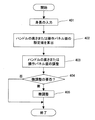
図4は本発明の実施形態1の移動型X線撮影装置における走行用ハンドルの高さ調整動作を説明するためのフローチャートであり、以下、図4に基づいて、実施形態1の走行用ハンドルの高さ調整動作を説明する。
<Heading handle height adjustment operation>
FIG. 4 is a flowchart for explaining the height adjustment operation of the traveling handle in the mobile X-ray imaging apparatus according to the first embodiment of the present invention. Hereinafter, the traveling handle according to the first embodiment will be described with reference to FIG. The height adjustment operation will be described.
移動型X線撮影装置を病室へ移動するに際し、操作者は装置の電源スイッチを投入するとともに、ハンドル部31の高さが自分に合っているか確認する。そしてハンドル部31の高さが自分に合っていないときは、ハンドル部31の高さ調整が以下の手順で行われる。すなわち、図4に示すフローの開始は、操作者によるハンドル部31の高さ判定となる。
When moving the mobile X-ray imaging apparatus to the hospital room, the operator turns on the power switch of the apparatus and confirms whether the height of the
ここで、操作者がハンドル部31の高さが自身の身長に適合していないと判断した場合、まず、操作者は操作パネル22へ設けられた身長入力器48から自分の身長の値を入力する(ステップ401)。
Here, when the operator determines that the height of the
操作パネル22へ入力された操作者の身長データは、CPU60へ出力される。CPU60は、操作者の身長データを受け取ると、その操作者に適したハンドル部31の高さを求める。(ステップ402)。ただし、操作者に適したハンドル部31の高さとは、操作者の肘の高さであって、望ましくは、操作者が歩行しているときの肘の高さとする。なお、操作者に適したハンドルの高さは、身長別に複数人数に装置の移動実験的を行い、その実験結果から定めてもよい。この場合、身長別に定めたハンドル部31の高さは、CPU60のメモリへテーブルデータとして予め格納しておき、操作者の身長入力に基づいて、CPU60がテーブルデータ内を検索し、入力された身長に対応したハンドル部31の高さを求めることによって実現可能である。なお、テーブルデータとして格納する身長のデータを、予め設定した複数のステップ値、例えば身長を、155cm以下、160cm、165cm、170cm、175cm以上のように区分けし、入力された操作者の身長データをそれらの値の最も近いものに近似させ、その値で走行用ハンドルの高さを調整する構成としてもよい。この場合、後述するモータの駆動制御も、ステップ的に制御することが可能となる。
The operator's height data input to the
CPU60からハンドルの高さに関するデータがハンドル移動用モータ駆動制御回路49に出力されると、ハンドル部31の高さ調整が行われる(ステップ403)。このステップ403でのハンドル部31の高さ調整では、まず、ハンドル移動用モータ駆動制御回路49が保持する現在のハンドル部31の高さデータと、CPU60より入力される高さデータとが比較される。次に、比較結果に基づいて、ハンドル移動用モータ駆動制御回路49はモータ45の回転方向と回転数を求め、得られた回転方向と回転数にしたがってモータ45が駆動される。このモータ45の駆動により、歯車46及び歯車44を介して送りねじ42が回転し、該送りねじ42に嵌合するナット部材43が矢印F方向へ移動させられる。その結果、ナット部材43へ結合されたハンドル支持具32と共にハンドル部31の高さが変更される、すなわち、走行用ハンドル30の高さが調整される。
When data relating to the handle height is output from the
そして、操作者は高さが調整されたハンドル部31の高さについて微調整が必要か否かを判定する(ステップ404)。この判定ステップ404は、操作者の体格の個人差を補償するために設けられている。
Then, the operator determines whether or not fine adjustment is necessary for the height of the
ステップ404において、操作者によってハンドル高さの微調整の「必要なし」と判断された場合は、ハンドル高さの調整フローは終了する。一方、ステップ404において、ハンドル高さの微調整の「必要あり」と判断された場合は、次のステップ405のハンドル高さ微調整に進む。
If it is determined in
ステップ405におけるハンドル高さの微調整は、操作パネル22の盤面に身長入力器49に付随して設けられた「+」「−」の微調整スイッチを操作者が操作することで行われる。微調整スイッチ「+」、「−」の操作結果はCPU60へ出力され、「+」又は「−」のいずれかが1回操作されると、所定の高さ、例えば1cmだけハンドルの高さが変わるようにモータ45の駆動制御が行われるようになっている。したがって、操作者は微調整スイッチを操作して、ハンドルを操作しやすい高さに調整した後に、移動型X線撮影装置を病室へ搬送することができる。なお、ステップ405のハンドル高さの微調整機構は、必要に応じて設けてもよい。
The fine adjustment of the handle height in
以上説明したように、本発明の実施形態1の移動型X線撮影装置では、走行用ハンドル30は、ハンドルの高さ調整が成される時に上下方向へ直線的に移動するので、台車の筐体とハンドル間の間隔が変化することがないので、ハンドルが握り難くなることはなく、また、ハンドルの高さを変えてもハンドルの向きが変わることはない。さらに、必要に応じてハンドル高さの微調整機構を設けることで、身長により設定されるハンドル高さの微調整ができるので、操作者が最適と感ずる高さにハンドル位置を設定することができ、操作者の身長が異なる場合における操作性を改善することができる。
As described above, in the mobile X-ray imaging apparatus according to the first embodiment of the present invention, the traveling
〈実施形態2〉
図5は本発明の実施形態1の移動型X線撮影装置におけるハンドル高さ調整機構及び操作パネル面の調整機構の詳細構成を説明するための図であり、以下、図5に基づいて、実施形態2のハンドル高さ調整機構及び操作パネル面調整機構を説明する。ただし、実施形態2の移動型X線撮影装置は走行用ハンドルの高さ調整機構及び操作パネル面の調整機構を除く他の構成は、実施形態1の移動用X線撮影装置と同様の構成となる。従って、以下の説明では、実施形態2の走行用ハンドル高さ調整機構及び操作パネル面の調整機構について、詳細に説明する。
<Embodiment 2>
FIG. 5 is a diagram for explaining the detailed configuration of the handle height adjustment mechanism and the operation panel surface adjustment mechanism in the mobile X-ray imaging apparatus according to the first embodiment of the present invention. A handle height adjusting mechanism and an operation panel surface adjusting mechanism according to the second embodiment will be described. However, the mobile X-ray apparatus according to the second embodiment is the same as the mobile X-ray apparatus according to the first embodiment except for the height adjustment mechanism of the traveling handle and the adjustment mechanism of the operation panel surface. Become. Therefore, in the following description, the traveling handle height adjustment mechanism and the operation panel surface adjustment mechanism of the second embodiment will be described in detail.
図5に示すように、実施形態2の移動型X線撮影装置では、操作パネル22と高さ調整機構40とがサイドフレーム53に固定されると共に、該サイドフレーム53は支点Gを中心として動作(回動、傾斜動作)する構成となっているので、サイドフレーム53の動作に伴って高さ調整機構40の配置側が図中の矢印J方向に上下動する。また、高さ調整機構40には実施形態1で説明したように、走行用ハンドル30が配置される構成となっているので、実施形態2では、サイドフレーム53の動作(傾斜動作)に伴う図中の矢印Jで示す傾斜方向への走行用ハンドル30の垂直(鉛直)方向の移動と、高さ調整機構40による矢印Jで示す方向への走行用ハンドル30のみの移動とによって、当該走行用ハンドル30の高さ調整が可能となっている。
As shown in FIG. 5, in the mobile X-ray imaging apparatus of the second embodiment, the
また、実施形態2では、サイドフレーム53に操作パネル22も配置される構成となっているので、サイドフレーム53の傾斜動作にとなって、操作パネル22も上下動される構成となっている。この場合、走行用ハンドル30の配置側を下げるようにサイドフレーム53を傾斜移動させた場合には、操作パネル22のパネル面(操作パネル面)が操作者の側に傾斜することとなる。一方、走行用ハンドル30の配置側を上げるようにサイドフレーム53を傾斜移動させた場合には、操作パネル22のパネル面(操作パネル面)は操作者と反対の側すなわち装置前部の側に傾斜することとなる。このために、実施形態2では、サイドフレーム53の傾斜に連動して、操作パネル22を操作者側に傾斜させる機構(操作パネル面高さ調節機構)を有している。この操作パネル22を傾斜させる機構は、操作パネル22の操作者側の一辺(下端側)を支持する周知のヒンジ機構と、操作パネル22の操作者から遠い側の裏面に配置され、サイドフレーム53の傾斜角に連動して突出量が変動する簡易バー(押し上げ部)50とから構成されている。
In the second embodiment, since the
次に、図6に本発明の実施形態2の移動型X線撮影装置の全体構成を説明するためのブロック図を示し、実施形態2の移動型X線撮影装置の動作を説明する。ただし、図6に示すブロック図から明らかなように、ハンドル及び操作パネル面移動用モータ駆動制御回路51及びモータ52を除く他の構成は実施形態1と同様の構成である。従って、以下の説明では、ハンドル及び操作パネル面移動用モータ駆動制御回路51及びモータ52について詳細に説明する。
Next, FIG. 6 is a block diagram for explaining the overall configuration of the mobile X-ray imaging apparatus according to the second embodiment of the present invention, and the operation of the mobile X-ray imaging apparatus according to the second embodiment will be described. However, as apparent from the block diagram shown in FIG. 6, the configuration other than the handle and operation panel surface moving motor
走行用ハンドル30及び操作パネル22の高さ調整については、まず、移動型X線撮影装置の使用に際し、操作者がハンドル部31または操作パネル面22の高さが自分に合っているか確認する。ここで、ハンドル部31または操作パネル面22の高さが自分に合っていないときは、操作パネル22へ設けられた身長入力器48から自分の身長の値を入力することにより、入力された身長データがCPU60へ出力される。
Regarding the height adjustment of the traveling
身長データを受け取ったCPU60は、身長データに適した走行用ハンドル30及び操作パネル面の高さを求める。このときの演算は、実施形態1と同様に、CPU60が予め格納されるテーブルデータから入力された身長データに対応した走行用ハンドル30及び操作パネル面の高さを検索し、得られたデータをハンドル及び操作パネル面移動用モータ駆動制御回路(第2制御手段)51に出力する。このCPU60から入力されたデータに基づいて、ハンドル及び操作パネル面移動用モータ駆動制御回路51は、モータ52を制御し、支点Gを中心にしてサイドフレーム53を移動させ、走行用ハンドル30および操作パネル面の高さの調整を行う。このとき、ハンドル及び操作パネル面移動用モータ駆動制御回路51が走行用ハンドル30の高さのみの調整が必要と判断したときは、ハンドル移動用モータ駆動制御回路49が保持する現在のハンドルの高さと、CPU60から入力された走行用ハンドル30の高さとから移動量を算出する。次に、この算出された移動量をCPU60を経由してハンドル移動用モータ駆動制御回路49に出力することにより、ハンドル移動用モータ駆動制御回路49がモータ45の回転方向と回転数を求める。そして、ハンドル移動用モータ駆動制御回路49が求められた回転方向と回転数にしたがって、モータ45を駆動することにより、走行用ハンドル30を所望高さに移動させる。
The
また、走行時においては、実施形態1と同様に、走行用ハンドル30に配置されたセンサで検出された検出量に応じてCPU60が走行用モータ駆動制御回路14aに制御データを出力する。走行用モータ駆動制御回路14aは、左側の駆動輪12を駆動するモータ(左)14b、及び右側の駆動輪12を駆動するモータ(右)14cを制御データに基づいて駆動することによって、走行用ハンドル30への操作に応じた走行がなされる。
Further, during traveling, as in the first embodiment, the
X線撮影時においても、実施形態1と同様に、操作者が手動操作によってX線管装置19を所望位置へ移動させた後に、操作パネル22からX線ビームの照射条件を設定することにより、CPU60がコリメータ20を制御して照射範囲を制限する。次に、撮影開始ボタンの押下により、CPU60がX線制御装置21を制御し、バッテリー16から高電圧を発生しX線管装置19に供給することにより、X線ビームが照射され、所望位置のX線撮影がなされる。
Even during X-ray imaging, as in the first embodiment, after the operator manually moves the
以上説明したように、実施形態2の移動型X線撮影装置では、操作者から遠い側の端部領域に支点Gを有するサイドフレームに、高さ調整機構を備える走行用ハンドルと操作パネルとを配置し、操作者の身長データに基づいてサイドフレームの傾斜角を変化させることによって、走行用ハンドルと操作パネルの高さを調整する構成となっているので、前述する実施形態1の効果に加えて、操作者の身長が平均身長と異なる場合における操作性をさらに向上させることができる。 As described above, in the mobile X-ray imaging apparatus according to the second embodiment, the traveling handle including the height adjustment mechanism and the operation panel are provided on the side frame having the fulcrum G in the end region far from the operator. Since the configuration is such that the height of the steering wheel and the operation panel is adjusted by changing the inclination angle of the side frame based on the height data of the operator, in addition to the effects of the first embodiment described above. Thus, the operability when the height of the operator is different from the average height can be further improved.
なお、実施形態1、2の移動型X線撮影装置では、走行用ハンドルの高さ調整機構は、送りねじ機構を用いる構成としたが、これに限定されることはない。例えば、送りねじ機構に代えて、走行用ハンドル機構をガイドするリニアモーションベアリング機構と、モータの出力軸へ設けた搖動アームとハンドル支持具との間に設けた搖動可能なリンクとで駆動機構を構成し、モータを回転させることで走行用ハンドル機構を移動させる構成でもよい。さらには、この構成とすることにより、走行用ハンドルの高さを複数ステップに設定することが容易となる。 In the mobile X-ray imaging apparatuses according to the first and second embodiments, the height adjustment mechanism of the traveling handle is configured to use the feed screw mechanism, but is not limited thereto. For example, instead of the feed screw mechanism, the drive mechanism is composed of a linear motion bearing mechanism that guides the traveling handle mechanism, and a swingable link provided between the swing arm provided on the output shaft of the motor and the handle support. It may be configured to move the traveling handle mechanism by rotating the motor. Furthermore, with this configuration, it becomes easy to set the height of the traveling handle to a plurality of steps.
以上、本発明者によってなされた発明を、前記発明の実施形態に基づき具体的に説明したが、本発明は、前記発明の実施形態に限定されるものではなく、その要旨を逸脱しない範囲において種々変更可能である。 As mentioned above, the invention made by the present inventor has been specifically described based on the embodiment of the invention. However, the invention is not limited to the embodiment of the invention, and various modifications can be made without departing from the scope of the invention. It can be changed.
11…台車、12…駆動輪、13…前輪、14…走行駆動機構
14a…走行用モータ駆動制御回路、14b…モータ(左)、14c…モータ(右)
15…筐体、16…バッテリー、17…支柱、18…X線管支持機構、19…X線管装置
20…コリメータ、21…X線制御装置、22…操作パネル、23…ロック機構
24…床面、30…走行用ハンドル機構、31…ハンドル部、32…ハンドル支持具
40…高さ調整機構、41…軸受け、42…送りねじ、43…ナット部材
44、46…歯車、45…モータ、47…リミットスイッチ、48…身長入力器
49…ハンドル移動用モータ駆動制御回路、50…簡易バー(押し上げ部)
51…ハンドル及び操作パネル面移動用モータ駆動制御回路、52…モータ
53…サイドフレーム、60…CPU
DESCRIPTION OF
DESCRIPTION OF
51 ... Motor drive control circuit for moving handle and operation panel surface, 52 ...
Claims (3)
前記走行用ハンドルの床面からの高さを変更するハンドル高さ調整機構と、前記X線の照射条件を設定する操作用パネルと、前記ハンドル高さ調整機構と前記操作用パネルを支持し、当該一辺を中心とし回転移動することで前記ハンドル高さ調整機構と前記操作用パネルを連動させながら上下方向へ移動させて床面からの高さを変更するフレームを有する操作パネル面調整機構と、前記走行用ハンドル、又は前記走行用ハンドルと前記操作用パネルの高さを設定する設定値入力手段と、前記設定値入力手段によって設定された設定値に基づいて前記ハンドル高さ調整機構及び/又は前記操作パネル面調整機構を用いて前記走行用ハンドル、又は前記走行用ハンドルと前記操作用パネルの高さを移動させる制御手段と、
を備えることを特徴とする移動型X線撮影装置。 An X-ray imaging unit having an X-ray generation unit that irradiates a subject with X-rays, a carriage on which the X-ray imaging unit is mounted, and a traveling handle that is installed on a side surface and a rear part of the carriage to control the traveling of the carriage. A mobile X-ray imaging apparatus comprising:
A handle height adjustment mechanism for changing the height of the traveling handle from the floor, an operation panel for setting the X-ray irradiation conditions, the handle height adjustment mechanism, and the operation panel are supported; An operation panel surface adjustment mechanism having a frame that moves in the vertical direction while interlocking the handle height adjustment mechanism and the operation panel by rotating around the one side, and changing the height from the floor surface, A setting value input means for setting the traveling handle, or the height of the traveling handle and the operation panel, the handle height adjusting mechanism based on the setting value set by the setting value input means, and / or Control means for moving the travel handle or the travel handle and the height of the operation panel using the operation panel surface adjustment mechanism;
A mobile X-ray imaging apparatus comprising:
Priority Applications (1)
| Application Number | Priority Date | Filing Date | Title |
|---|---|---|---|
| JP2009180331A JP5426268B2 (en) | 2009-08-03 | 2009-08-03 | Mobile X-ray equipment |
Applications Claiming Priority (1)
| Application Number | Priority Date | Filing Date | Title |
|---|---|---|---|
| JP2009180331A JP5426268B2 (en) | 2009-08-03 | 2009-08-03 | Mobile X-ray equipment |
Publications (3)
| Publication Number | Publication Date |
|---|---|
| JP2011030816A JP2011030816A (en) | 2011-02-17 |
| JP2011030816A5 JP2011030816A5 (en) | 2012-09-06 |
| JP5426268B2 true JP5426268B2 (en) | 2014-02-26 |
Family
ID=43760478
Family Applications (1)
| Application Number | Title | Priority Date | Filing Date |
|---|---|---|---|
| JP2009180331A Expired - Fee Related JP5426268B2 (en) | 2009-08-03 | 2009-08-03 | Mobile X-ray equipment |
Country Status (1)
| Country | Link |
|---|---|
| JP (1) | JP5426268B2 (en) |
Families Citing this family (4)
| Publication number | Priority date | Publication date | Assignee | Title |
|---|---|---|---|---|
| JP6242060B2 (en) * | 2013-02-19 | 2017-12-06 | キヤノン株式会社 | Mobile X-ray equipment |
| JP5543003B1 (en) * | 2013-09-20 | 2014-07-09 | 株式会社東芝 | Mobile X-ray diagnostic device |
| JP2015058341A (en) * | 2014-02-19 | 2015-03-30 | 株式会社東芝 | Mobile device |
| US11197649B2 (en) * | 2018-03-23 | 2021-12-14 | Shimadzu Corporation | Mobile radiation imaging apparatus |
Family Cites Families (7)
| Publication number | Priority date | Publication date | Assignee | Title |
|---|---|---|---|---|
| JPS60105558U (en) * | 1983-12-26 | 1985-07-18 | 日本電気株式会社 | Height adjustable handle push cart |
| NL8600215A (en) * | 1986-01-30 | 1987-08-17 | Philips Nv | SURGICAL ROENTGEN EXAMINATION DEVICE. |
| JP3040162U (en) * | 1996-11-12 | 1997-08-15 | 金蔵 山田 | A walking trainer with an oxygen cylinder that doubles as a gantry rack |
| JP3957125B2 (en) * | 2000-08-29 | 2007-08-15 | ピジョン株式会社 | Walking aid |
| JP2004275326A (en) * | 2003-03-14 | 2004-10-07 | Konica Minolta Holdings Inc | Mammographic image photographic apparatus |
| JP5056022B2 (en) * | 2007-01-18 | 2012-10-24 | 株式会社島津製作所 | Round-trip X-ray equipment |
| JP3142429U (en) * | 2008-04-01 | 2008-06-12 | 株式会社島津製作所 | Mobile X-ray imaging device |
-
2009
- 2009-08-03 JP JP2009180331A patent/JP5426268B2/en not_active Expired - Fee Related
Also Published As
| Publication number | Publication date |
|---|---|
| JP2011030816A (en) | 2011-02-17 |
Similar Documents
| Publication | Publication Date | Title |
|---|---|---|
| US8739334B2 (en) | Iso-roll table | |
| JP4797899B2 (en) | Mobile X-ray equipment | |
| JP6310060B2 (en) | Assistance robot | |
| US10993682B2 (en) | Radiographic imaging apparatus comprising a leg unit having three or more wheel units | |
| JP6548451B2 (en) | Mobile X-ray diagnostic device | |
| US20120207282A1 (en) | X-ray imaging apparatus | |
| JP5426268B2 (en) | Mobile X-ray equipment | |
| JP6057015B2 (en) | Mobile X-ray equipment | |
| JP5222686B2 (en) | Mobile X-ray equipment | |
| JP6066247B1 (en) | Radiation irradiation equipment | |
| WO2013047438A1 (en) | Mobile diagnostic x-ray equipment and method for controlling mobile diagnostic x-ray equipment | |
| JP5508891B2 (en) | Mobile X-ray equipment | |
| WO2014119164A1 (en) | Radiography device | |
| JP2018134430A (en) | Assistance robot | |
| US20130259209A1 (en) | X-ray diagnostic system | |
| JP2002209885A (en) | X-ray diagnostic instrument for medical use | |
| JP6400170B2 (en) | Mobile X-ray imaging device | |
| JP6066246B1 (en) | Radiation irradiation equipment | |
| JP2000070244A (en) | X-ray device for medical use | |
| JP7327125B2 (en) | X-ray equipment | |
| JP6722811B2 (en) | Assistance robot | |
| JP5414408B2 (en) | Mobile X-ray device | |
| JP2006025942A (en) | X-ray radiographing device | |
| CN116158772A (en) | Universal positioning system for an X-ray imaging system | |
| JP6127936B2 (en) | X-ray equipment |
Legal Events
| Date | Code | Title | Description |
|---|---|---|---|
| RD05 | Notification of revocation of power of attorney |
Free format text: JAPANESE INTERMEDIATE CODE: A7425 Effective date: 20110107 |
|
| A521 | Request for written amendment filed |
Free format text: JAPANESE INTERMEDIATE CODE: A523 Effective date: 20120724 |
|
| A621 | Written request for application examination |
Free format text: JAPANESE INTERMEDIATE CODE: A621 Effective date: 20120724 |
|
| A131 | Notification of reasons for refusal |
Free format text: JAPANESE INTERMEDIATE CODE: A131 Effective date: 20130603 |
|
| A521 | Request for written amendment filed |
Free format text: JAPANESE INTERMEDIATE CODE: A523 Effective date: 20130718 |
|
| A131 | Notification of reasons for refusal |
Free format text: JAPANESE INTERMEDIATE CODE: A131 Effective date: 20130819 |
|
| A521 | Request for written amendment filed |
Free format text: JAPANESE INTERMEDIATE CODE: A523 Effective date: 20130927 |
|
| TRDD | Decision of grant or rejection written | ||
| A01 | Written decision to grant a patent or to grant a registration (utility model) |
Free format text: JAPANESE INTERMEDIATE CODE: A01 Effective date: 20131105 |
|
| A61 | First payment of annual fees (during grant procedure) |
Free format text: JAPANESE INTERMEDIATE CODE: A61 Effective date: 20131128 |
|
| R150 | Certificate of patent or registration of utility model |
Free format text: JAPANESE INTERMEDIATE CODE: R150 |
|
| LAPS | Cancellation because of no payment of annual fees |