JP5425465B2 - Fuel cell apparatus and method - Google Patents
Fuel cell apparatus and method Download PDFInfo
- Publication number
- JP5425465B2 JP5425465B2 JP2008512597A JP2008512597A JP5425465B2 JP 5425465 B2 JP5425465 B2 JP 5425465B2 JP 2008512597 A JP2008512597 A JP 2008512597A JP 2008512597 A JP2008512597 A JP 2008512597A JP 5425465 B2 JP5425465 B2 JP 5425465B2
- Authority
- JP
- Japan
- Prior art keywords
- fuel cell
- housing
- fuel
- conduit
- heat
- Prior art date
- Legal status (The legal status is an assumption and is not a legal conclusion. Google has not performed a legal analysis and makes no representation as to the accuracy of the status listed.)
- Expired - Fee Related
Links
Images


Classifications
-
- H—ELECTRICITY
- H01—ELECTRIC ELEMENTS
- H01M—PROCESSES OR MEANS, e.g. BATTERIES, FOR THE DIRECT CONVERSION OF CHEMICAL ENERGY INTO ELECTRICAL ENERGY
- H01M8/00—Fuel cells; Manufacture thereof
- H01M8/04—Auxiliary arrangements, e.g. for control of pressure or for circulation of fluids
- H01M8/04298—Processes for controlling fuel cells or fuel cell systems
- H01M8/04694—Processes for controlling fuel cells or fuel cell systems characterised by variables to be controlled
- H01M8/04746—Pressure; Flow
- H01M8/04776—Pressure; Flow at auxiliary devices, e.g. reformer, compressor, burner
-
- H—ELECTRICITY
- H01—ELECTRIC ELEMENTS
- H01M—PROCESSES OR MEANS, e.g. BATTERIES, FOR THE DIRECT CONVERSION OF CHEMICAL ENERGY INTO ELECTRICAL ENERGY
- H01M8/00—Fuel cells; Manufacture thereof
- H01M8/04—Auxiliary arrangements, e.g. for control of pressure or for circulation of fluids
- H01M8/04007—Auxiliary arrangements, e.g. for control of pressure or for circulation of fluids related to heat exchange
-
- H—ELECTRICITY
- H01—ELECTRIC ELEMENTS
- H01M—PROCESSES OR MEANS, e.g. BATTERIES, FOR THE DIRECT CONVERSION OF CHEMICAL ENERGY INTO ELECTRICAL ENERGY
- H01M8/00—Fuel cells; Manufacture thereof
- H01M8/04—Auxiliary arrangements, e.g. for control of pressure or for circulation of fluids
- H01M8/04082—Arrangements for control of reactant parameters, e.g. pressure or concentration
- H01M8/04186—Arrangements for control of reactant parameters, e.g. pressure or concentration of liquid-charged or electrolyte-charged reactants
-
- H—ELECTRICITY
- H01—ELECTRIC ELEMENTS
- H01M—PROCESSES OR MEANS, e.g. BATTERIES, FOR THE DIRECT CONVERSION OF CHEMICAL ENERGY INTO ELECTRICAL ENERGY
- H01M8/00—Fuel cells; Manufacture thereof
- H01M8/04—Auxiliary arrangements, e.g. for control of pressure or for circulation of fluids
- H01M8/04298—Processes for controlling fuel cells or fuel cell systems
- H01M8/04313—Processes for controlling fuel cells or fuel cell systems characterised by the detection or assessment of variables; characterised by the detection or assessment of failure or abnormal function
- H01M8/0432—Temperature; Ambient temperature
- H01M8/04365—Temperature; Ambient temperature of other components of a fuel cell or fuel cell stacks
-
- H—ELECTRICITY
- H01—ELECTRIC ELEMENTS
- H01M—PROCESSES OR MEANS, e.g. BATTERIES, FOR THE DIRECT CONVERSION OF CHEMICAL ENERGY INTO ELECTRICAL ENERGY
- H01M8/00—Fuel cells; Manufacture thereof
- H01M8/04—Auxiliary arrangements, e.g. for control of pressure or for circulation of fluids
- H01M8/04298—Processes for controlling fuel cells or fuel cell systems
- H01M8/04313—Processes for controlling fuel cells or fuel cell systems characterised by the detection or assessment of variables; characterised by the detection or assessment of failure or abnormal function
- H01M8/0432—Temperature; Ambient temperature
- H01M8/04373—Temperature; Ambient temperature of auxiliary devices, e.g. reformers, compressors, burners
-
- H—ELECTRICITY
- H01—ELECTRIC ELEMENTS
- H01M—PROCESSES OR MEANS, e.g. BATTERIES, FOR THE DIRECT CONVERSION OF CHEMICAL ENERGY INTO ELECTRICAL ENERGY
- H01M8/00—Fuel cells; Manufacture thereof
- H01M8/04—Auxiliary arrangements, e.g. for control of pressure or for circulation of fluids
- H01M8/04298—Processes for controlling fuel cells or fuel cell systems
- H01M8/04313—Processes for controlling fuel cells or fuel cell systems characterised by the detection or assessment of variables; characterised by the detection or assessment of failure or abnormal function
- H01M8/0438—Pressure; Ambient pressure; Flow
- H01M8/04425—Pressure; Ambient pressure; Flow at auxiliary devices, e.g. reformers, compressors, burners
-
- H—ELECTRICITY
- H01—ELECTRIC ELEMENTS
- H01M—PROCESSES OR MEANS, e.g. BATTERIES, FOR THE DIRECT CONVERSION OF CHEMICAL ENERGY INTO ELECTRICAL ENERGY
- H01M8/00—Fuel cells; Manufacture thereof
- H01M8/04—Auxiliary arrangements, e.g. for control of pressure or for circulation of fluids
- H01M8/04298—Processes for controlling fuel cells or fuel cell systems
- H01M8/04313—Processes for controlling fuel cells or fuel cell systems characterised by the detection or assessment of variables; characterised by the detection or assessment of failure or abnormal function
- H01M8/0438—Pressure; Ambient pressure; Flow
- H01M8/04432—Pressure differences, e.g. between anode and cathode
-
- H—ELECTRICITY
- H01—ELECTRIC ELEMENTS
- H01M—PROCESSES OR MEANS, e.g. BATTERIES, FOR THE DIRECT CONVERSION OF CHEMICAL ENERGY INTO ELECTRICAL ENERGY
- H01M8/00—Fuel cells; Manufacture thereof
- H01M8/04—Auxiliary arrangements, e.g. for control of pressure or for circulation of fluids
- H01M8/04298—Processes for controlling fuel cells or fuel cell systems
- H01M8/04694—Processes for controlling fuel cells or fuel cell systems characterised by variables to be controlled
- H01M8/04701—Temperature
- H01M8/04738—Temperature of auxiliary devices, e.g. reformer, compressor, burner
-
- H—ELECTRICITY
- H01—ELECTRIC ELEMENTS
- H01M—PROCESSES OR MEANS, e.g. BATTERIES, FOR THE DIRECT CONVERSION OF CHEMICAL ENERGY INTO ELECTRICAL ENERGY
- H01M8/00—Fuel cells; Manufacture thereof
- H01M8/24—Grouping of fuel cells, e.g. stacking of fuel cells
- H01M8/2465—Details of groupings of fuel cells
- H01M8/247—Arrangements for tightening a stack, for accommodation of a stack in a tank or for assembling different tanks
- H01M8/2475—Enclosures, casings or containers of fuel cell stacks
-
- H—ELECTRICITY
- H01—ELECTRIC ELEMENTS
- H01M—PROCESSES OR MEANS, e.g. BATTERIES, FOR THE DIRECT CONVERSION OF CHEMICAL ENERGY INTO ELECTRICAL ENERGY
- H01M8/00—Fuel cells; Manufacture thereof
- H01M8/10—Fuel cells with solid electrolytes
- H01M8/12—Fuel cells with solid electrolytes operating at high temperature, e.g. with stabilised ZrO2 electrolyte
- H01M2008/1293—Fuel cells with solid oxide electrolytes
-
- H—ELECTRICITY
- H01—ELECTRIC ELEMENTS
- H01M—PROCESSES OR MEANS, e.g. BATTERIES, FOR THE DIRECT CONVERSION OF CHEMICAL ENERGY INTO ELECTRICAL ENERGY
- H01M8/00—Fuel cells; Manufacture thereof
- H01M8/04—Auxiliary arrangements, e.g. for control of pressure or for circulation of fluids
- H01M8/04007—Auxiliary arrangements, e.g. for control of pressure or for circulation of fluids related to heat exchange
- H01M8/04014—Heat exchange using gaseous fluids; Heat exchange by combustion of reactants
- H01M8/04022—Heating by combustion
-
- H—ELECTRICITY
- H01—ELECTRIC ELEMENTS
- H01M—PROCESSES OR MEANS, e.g. BATTERIES, FOR THE DIRECT CONVERSION OF CHEMICAL ENERGY INTO ELECTRICAL ENERGY
- H01M8/00—Fuel cells; Manufacture thereof
- H01M8/04—Auxiliary arrangements, e.g. for control of pressure or for circulation of fluids
- H01M8/04082—Arrangements for control of reactant parameters, e.g. pressure or concentration
- H01M8/04089—Arrangements for control of reactant parameters, e.g. pressure or concentration of gaseous reactants
-
- H—ELECTRICITY
- H01—ELECTRIC ELEMENTS
- H01M—PROCESSES OR MEANS, e.g. BATTERIES, FOR THE DIRECT CONVERSION OF CHEMICAL ENERGY INTO ELECTRICAL ENERGY
- H01M8/00—Fuel cells; Manufacture thereof
- H01M8/06—Combination of fuel cells with means for production of reactants or for treatment of residues
- H01M8/0606—Combination of fuel cells with means for production of reactants or for treatment of residues with means for production of gaseous reactants
- H01M8/0612—Combination of fuel cells with means for production of reactants or for treatment of residues with means for production of gaseous reactants from carbon-containing material
-
- H—ELECTRICITY
- H01—ELECTRIC ELEMENTS
- H01M—PROCESSES OR MEANS, e.g. BATTERIES, FOR THE DIRECT CONVERSION OF CHEMICAL ENERGY INTO ELECTRICAL ENERGY
- H01M8/00—Fuel cells; Manufacture thereof
- H01M8/06—Combination of fuel cells with means for production of reactants or for treatment of residues
- H01M8/0662—Treatment of gaseous reactants or gaseous residues, e.g. cleaning
-
- Y—GENERAL TAGGING OF NEW TECHNOLOGICAL DEVELOPMENTS; GENERAL TAGGING OF CROSS-SECTIONAL TECHNOLOGIES SPANNING OVER SEVERAL SECTIONS OF THE IPC; TECHNICAL SUBJECTS COVERED BY FORMER USPC CROSS-REFERENCE ART COLLECTIONS [XRACs] AND DIGESTS
- Y02—TECHNOLOGIES OR APPLICATIONS FOR MITIGATION OR ADAPTATION AGAINST CLIMATE CHANGE
- Y02E—REDUCTION OF GREENHOUSE GAS [GHG] EMISSIONS, RELATED TO ENERGY GENERATION, TRANSMISSION OR DISTRIBUTION
- Y02E60/00—Enabling technologies; Technologies with a potential or indirect contribution to GHG emissions mitigation
- Y02E60/30—Hydrogen technology
- Y02E60/50—Fuel cells
Description
発明は、燃料電池効率と安全性を改善する装置と方法に関する。1つの実施形態において、発明は、多数の燃料電池構成要素を等温ゾーンにおいて一体化することによって、エネルギーバランスを改善するように適合した燃料電池に関する。 The invention relates to an apparatus and method for improving fuel cell efficiency and safety. In one embodiment, the invention relates to a fuel cell adapted to improve energy balance by integrating multiple fuel cell components in an isothermal zone.
例えば、気体水素、メタノール、ブタン、またはディーゼル燃料で充填された交換可能な燃料容器を伴って動作する燃料電池は、発展しつつある技術である。このようなタイプの燃料電池は、消費者製品に電力供給するさまざまなバッテリーソリューションと競合するように設計されている。バッテリーに対するこのような燃料電池の競争力は、多くの要因に依存している。例えば、容器中の燃料のエネルギー密度、特定の効率で化学エネルギーを電気エネルギーに変換する燃料電池の能力、ならびに燃料電池スタックおよび関連する流体ポンプおよび電力制御構成要素を、競合するバッテリーの物よりも大きくせずにしておく必要性、等の要因に依存している。 For example, fuel cells that operate with replaceable fuel containers filled with gaseous hydrogen, methanol, butane, or diesel fuel are an evolving technology. These types of fuel cells are designed to compete with various battery solutions that power consumer products. The competitiveness of such fuel cells over batteries depends on many factors. For example, the energy density of the fuel in the vessel, the ability of the fuel cell to convert chemical energy to electrical energy with a certain efficiency, and the fuel cell stack and associated fluid pump and power control components over those of competing batteries It depends on factors such as the need to keep it small.
エネルギー密度と化学的変換効率における改善は、高分子膜の代わりにセラミック膜を利用する固体電解質型燃料電池(SOFC)で達成されてきた。固体電解質型燃料電池は、各種炭化水素等、種々異なる分子燃料タイプを電気に変換することができるので、固体電解質型燃料電池は、エネルギー密度のある液体燃料を利用することができ、さらに適切なエネルギー変換効率を達成することができる。 Improvements in energy density and chemical conversion efficiency have been achieved in solid oxide fuel cells (SOFC) that utilize ceramic membranes instead of polymer membranes. Since the solid oxide fuel cell can convert various molecular fuel types such as various hydrocarbons into electricity, the solid oxide fuel cell can use liquid fuel with energy density, and more suitable Energy conversion efficiency can be achieved.
しかし、固体電解質型燃料電池は、膜と、600℃を超過する(多くの場合750℃を超える)触媒動作とを必要とする。従って、携帯型電源用途の固体電解質型燃料電池の設計者は、全体システムのサイズを極端に増加することなく、極度の熱からエンドユーザーを保護しなければならない。さらに、800℃で動作する現在の固体電解質型燃料電池は、ユーザーに供給される電気エネルギーよりも10倍多くのエネルギーを廃熱として環境に容易に放射または伝達する。そのようなシステムは、10%効率を超えることができない。すなわち、システムは、反応器の800℃動作温度を維持する目的のみのために90%を超過する燃料エネルギーを使用している。従って、このような低効率では、現在の固体電解質型燃料電池はバッテリーと競合することができそうもない。 However, solid oxide fuel cells require membranes and catalytic operation above 600 ° C. (often above 750 ° C.). Therefore, designers of solid oxide fuel cells for portable power applications must protect end users from extreme heat without significantly increasing the size of the overall system. In addition, current solid oxide fuel cells operating at 800 ° C. easily radiate or transmit 10 times more energy as waste heat to the environment than the electrical energy supplied to the user. Such a system cannot exceed 10% efficiency. That is, the system uses over 90% fuel energy only for the purpose of maintaining the 800 ° C. operating temperature of the reactor. Therefore, at such low efficiency, current solid oxide fuel cells are unlikely to be able to compete with the battery.
最新型の携帯型固体電解質型燃料電池は、バッテリーと同様の体積を達成することができていない。固体電解質型燃料電池発電機は、断熱材(insulation)なしでは、0.35ワット毎立方センチメートル(W/cc)を超えることは稀である。エネルギー効率的な動作のために充分な厚みを有する断熱層を追加すると、通常の固体電解質型燃料電池が提供する体積に対する出力の比率は、0.1W/ccを下回る。 Modern portable solid oxide fuel cells have not been able to achieve the same volume as batteries. Solid oxide fuel cell generators rarely exceed 0.35 watts per cubic centimeter (W / cc) without insulation. With the addition of a thermal insulation layer with sufficient thickness for energy efficient operation, the ratio of power to volume provided by a conventional solid oxide fuel cell is below 0.1 W / cc.
さらに、既存の燃料電池装置およびシステム設計は、システムの効率を高めるため、(固体電解質型燃料電池スタック以外の)加熱された構成要素を提供する。しかし、各加熱された構成要素は、装置の体積と過剰な熱損失を回避するため必要な断熱材の量とを追加する。 Further, existing fuel cell devices and system designs provide heated components (other than solid oxide fuel cell stacks) to increase system efficiency. However, each heated component adds the volume of equipment and the amount of insulation needed to avoid excessive heat loss.
その結果、携帯型燃料容器と組み合わせて、充電式バッテリーのエネルギー貯蔵容量と同様か、または凌駕するエネルギー貯蔵容量(例えば200ワット−時間毎リットル(W−時間/L)を上回る、好ましくは400W−時間/Lを上回る)を提供することができるミニチュア燃料電池装置を構築する必要性が存在する。今日、バッテリーのエネルギー容量によってその機能がしばしば制約される携帯型電子機器に電力供給するため、燃料電池は大いに価値あるものとなろう。さらに、個別の消費者に多くの所定の潜在的電力供給用途があることを考慮すると、個別のユーザーに安全である燃料電池は、大いに価値あるものでもある。 As a result, in combination with a portable fuel container, an energy storage capacity similar to or surpassing the energy storage capacity of a rechargeable battery (eg, exceeding 200 watt-hour per liter (W-hour / L), preferably 400 W- There is a need to build a miniature fuel cell device that can provide (greater than time / L). Today, fuel cells will be of great value because they power portable electronic devices whose function is often limited by the energy capacity of the battery. In addition, fuel cells that are safe for individual users are also of great value given that there are many predetermined potential power supply applications for individual consumers.
発明の要旨
燃料効率は、一部には熱効率を調節することにより達成される。特に、改善された熱効率は、一部には次の要因のいずれかまたはその組み合わせの結果による。すなわち、燃料改質器、燃料電池、および後部ガスバーナー(tail gas burner)の単一の、本質的に等温の、高温ゾーンへの一体化。燃料電池スタックの出力密度を、好ましくは、2W/ccを超過する値へ増加させることにより、熱いゾーンの熱放散領域を実質的に削減すること。高温動作を必要とする全構成要素が、単一のハウジング内に含まれるような、断熱材の効率的な(エアロゲルにしろ真空にしろ)手段の使用であって、そのような断熱材がハウジングの外部に配置されている手段の使用。燃料電池装置と外部との間で流体を交換し、燃料電池から電流を抽出するための低熱伝導接続の組み込み。および/または、好ましくは断熱ゾーン内に配置された熱回収器の組み込みであって、熱回収器は、熱いゾーンと外部周囲の温度の中間の温度で動作することができる組み込み。
SUMMARY OF THE INVENTION Fuel efficiency is achieved in part by adjusting thermal efficiency. In particular, the improved thermal efficiency is due in part to the result of any one or combination of the following factors. That is, the integration of the fuel reformer, fuel cell, and tail gas burner into a single, essentially isothermal, hot zone. Substantially reducing the heat dissipation area of the hot zone by increasing the power density of the fuel cell stack, preferably to a value exceeding 2 W / cc. Use of efficient means of insulation (either airgel or vacuum), such that all components requiring high temperature operation are contained within a single housing, such insulation being the housing Use of means located outside the door. Incorporation of a low thermal conductivity connection to exchange fluid between the fuel cell device and the outside and extract current from the fuel cell. And / or the incorporation of a heat recovery unit, preferably located in an adiabatic zone, wherein the heat recovery unit can operate at a temperature intermediate between the hot zone and the ambient ambient temperature.
本明細書で使用する「燃料電池装置」および「燃料電池システム」とは、次の構成要素の一部または全部を含み得る装置または機器を意味する。すなわち、燃料改質器、後部ガスバーナー、アノード/電解質/カソード要素、ポンプ、および制御である。しかし、「燃料電池」は、アノード/電解質/カソード膜構造を意味する。さらに、「出力密度」は、所与の体積中で生成された出力の比率を意味し、および燃料電池技術で理解されるような他の意味である。 As used herein, “fuel cell apparatus” and “fuel cell system” mean an apparatus or apparatus that may include some or all of the following components. Fuel reformer, rear gas burner, anode / electrolyte / cathode element, pump, and control. However, “fuel cell” means an anode / electrolyte / cathode membrane structure. Furthermore, “power density” refers to the proportion of power produced in a given volume, and other meanings as understood in fuel cell technology.
発明は、異なる局面と実施形態に関するが、本明細書に開示の異なる局面と実施形態は、適切に、全体または一部として共に一体化され得ることが理解される。従って、本明細書に開示の各実施形態は、所与の実施のために適切な程度に改変されて各局面において一体化され得る。さらに、局面および実施形態の一部は、「ための手段(means for)」用語を使用して記載されているが、本明細書に開示された全ての、局面、実施形態、および他の概念は、特定の「ための手段」用語が記載の特定の部分において使用されていないとしても、ミーンズプラスファンクションクレームのサポートとして作用し得ることが理解される。 Although the invention relates to different aspects and embodiments, it is understood that the different aspects and embodiments disclosed herein may be suitably integrated together in whole or in part. Thus, each embodiment disclosed herein may be modified and integrated in each aspect as appropriate for a given implementation. Furthermore, although some aspects and embodiments have been described using the term “means for”, all aspects, embodiments, and other concepts disclosed herein are also contemplated. It is understood that even if a specific “means for” term is not used in a particular part of the description, it can act as a support for means-plus-function claims.
用語「a」、「an」、および「the」は、特に別に規定していなければ「1以上」を意味する。 The terms “a”, “an”, and “the” mean “one or more” unless otherwise specified.
本明細書で使用する「と連絡する」は、直接または間接に連絡することを意味し、例えば、壁、管、半導体トレースおよび層、配線、ならびに他の当業者に公知の手段、ならびにこれらの組み合わせのような適切な接続を介する等の直接的または間接的接触である。 As used herein, “contacting” means contacting directly or indirectly, such as walls, tubes, semiconductor traces and layers, wiring, and other means known to those skilled in the art, and these Direct or indirect contact, such as through an appropriate connection such as a combination.
1つの局面において、発明は、ハウジングおよび1以上の安全機構を含む燃料電池装置に関する。 In one aspect, the invention relates to a fuel cell device that includes a housing and one or more safety mechanisms.
発明の、先述のならびに他の特徴および長所は、発明自体と共に、説明、図面、および特許請求の範囲からさらに充分に理解されるであろう。 The foregoing and other features and advantages of the invention, as well as the invention itself, will be more fully understood from the description, drawings, and claims.
次の説明は、本発明の特定の実施形態を例示する添付の図面を参照する。別の実施形態が可能であり、発明の精神と範囲から逸脱することなく実施形態に対して改変がなされ得る。従って、次の詳細な説明は本発明を限定する意図ではなく、本発明の範囲は添付の特許請求の範囲によって規定される。 The following description refers to the accompanying drawings that illustrate specific embodiments of the invention. Other embodiments are possible and modifications may be made to the embodiments without departing from the spirit and scope of the invention. The following detailed description is, therefore, not intended to limit the invention, the scope of the invention being defined by the appended claims.
発明の方法の工程の順序は、発明が実施できる限り重要ではないことが理解されるべきである。さらに2つ以上の工程が、別に特定しない限り同時になされ得る。 It should be understood that the order of steps of the inventive method is not critical as long as the invention can be practiced. Further, two or more steps can be performed simultaneously unless specified otherwise.
一体型燃料電池装置、パッケージ、および接続
本明細書中に記載した燃料電池装置実施形態は、2W/ccを超えて、および3W/ccを超えて電力を生成することができる。このような燃料電池装置は、出力定格が100ワット未満、20ワット未満、または5ワット未満であっても、携帯用途のために充分に小さい断熱したパッケージサイズに独自に製造することができる。それに対して、既存の燃料電池設計は、典型的には、0.5W/cc未満の出力密度を発生するだけである。その結果、低出力密度燃料電池は大きすぎて、例えば民生用バッテリー代替品のような多くの用途に対して充分に効率的ではない。
Integrated Fuel Cell Device, Package, and Connection The fuel cell device embodiments described herein can generate power in excess of 2 W / cc and in excess of 3 W / cc. Such fuel cell devices can be uniquely manufactured in insulated package sizes that are small enough for portable applications, even if the power rating is less than 100 watts, less than 20 watts, or less than 5 watts. In contrast, existing fuel cell designs typically only produce power densities of less than 0.5 W / cc. As a result, low power density fuel cells are too large and are not efficient enough for many applications such as consumer battery replacements.
出力密度(W/cc)は、一体型燃料電池装置および個別の燃料電池または燃料電池スタック(複数の個別の燃料電池)の設計に主に依存する。特に、ハウジング内の種々の燃料電池装置構成要素の近接的一体性の程度は、重要な設計要因である。その結果、燃料電池装置効率は、機械的強度と流路の制約を条件として、種々の燃料電池膜がどれだけ近接して配置され得るか、の関数であることができる。本明細書に記載した多くの局面と実施形態は、1つの熱的領域内における構成要素の一体性と熱損失の制御に関連する技術とに関する。本明細書に開示の多くの実施形態において半導体構造を使用することで、小型サイズと高エネルギー密度を可能とし、これにより、燃料電池装置が各種バッテリータイプと競合することができる。 The power density (W / cc) mainly depends on the design of the integrated fuel cell device and individual fuel cells or fuel cell stacks (multiple individual fuel cells). In particular, the degree of proximity integrity of the various fuel cell device components within the housing is an important design factor. As a result, fuel cell device efficiency can be a function of how close the various fuel cell membranes can be placed, subject to mechanical strength and flow path constraints. Many aspects and embodiments described herein relate to techniques related to component integrity and heat loss control within a thermal region. The use of semiconductor structures in many embodiments disclosed herein allows for small size and high energy density, which allows the fuel cell device to compete with various battery types.
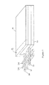
図1は、燃料電池装置5の1つの実施例を断面図で示す。図1は、燃料改質器10、一対の固体電解質型燃料電池膜14および16、ならびに後部ガスバーナー12を示し、これら全てが単一のハウジング18内に含まれる。ハウジングは、熱伝導材で作製されているので、ハウジング内の構成要素の全ては、実質的に同一温度で動作することができる。従って、ハウジングは、実質的に等温であるゾーンの形成を容易としている。
FIG. 1 shows a cross-sectional view of one embodiment of a fuel cell device 5. FIG. 1 shows a
図1のハウジング18は、その中に、燃料と空気を燃料電池セル(複数)に分配するための全ての流路手段を含む。燃料流20は、燃料改質器10から第1の燃料電池16のアノード側に沿って流れていく。燃料流20’は、その後、第2の燃料電池14のアノード側22に沿って流れて、最終的に、後部ガスバーナー12に至る。空気流26は、(図示しない内部経路チャンネルによって)燃料電池14、16のカソード側24に沿って流れて、後部ガスバーナー12に到達し、ここでは、未使用の排出燃料の燃焼のために過剰空気が利用可能である。(ガスバーナーへの空気の導入は、図1に現れない。)
The
また、図1には、断熱空間(insulating volume)28を示し、これは、ハウジング18を装置5の外壁30から分離する。外壁は、実質的に、燃料電池装置によって電力供給される電気機器の周囲温度またはその付近の温度で維持される。固体電解質型燃料電池装置の効率的な運転のために、ハウジング内の温度は、400℃を越えなければならず、温度が、550℃、600℃、または750℃を超えて維持されると、さらに良好な運転効率が得られる。外部電気回路の周囲温度および燃料電池装置の外壁30は、典型的には0℃から60℃までの範囲であろう。従ってこの実施形態においては、介在する断熱空間28の厚みを通じてのみならず、流体接続32、電気接続36に沿って、および機械支持38に沿っても、300℃を超過する大きな熱勾配が望ましくは維持される。
Further, in FIG. 1 shows a heat insulation space (insulating volume) 28, which separates the
断熱空間は、断熱材を一体化してハウジングからの熱放散を実質的に削減することができる。従って、断熱空間内で部分的に真空が形成されてよく、または低熱伝導材が断熱空間に添加されてもよい。赤外放射シールド40も、燃料電池装置の内部または上に配置されてよい。低圧または真空断熱材実施形態を製作するとき、断熱空間内の全ガス圧を必要な低いレベルに維持することが有益である。この目的のため、背景ガスを吸収し、機器の作動寿命にわたって高レベルの真空を維持する能力を有するゲッター材42を追加することが有用である。電気的加熱の間作動され得る非蒸発性のゲッターは、この目的のために有用であり、SAESゲッターST171デバイス(www.saesgetters.com)などがある。
The heat insulating space can integrate heat insulating material to substantially reduce heat dissipation from the housing. Therefore, well partial vacuum within the insulation space is formed, or low thermal conductivity material may be added to the heat-insulating space. The
ハウジング内部に含まれる一体型燃料電池は2.5mmの全体の厚みを有することができる。図1において、2つの燃料電池層14および16、ならびに、3個の経路層46、48、および50が存在し、それぞれ0.5mmの厚みを有する。2つの燃料電池層のそれぞれは、0.4W/cm2の電力を生成することができる。その結果、代表的な一体型燃料電池装置は、(2*0.4)/2.5=3.2W/ccの出力密度を送達することができる。 The integrated fuel cell contained within the housing can have an overall thickness of 2.5 mm. In FIG. 1, there are two fuel cell layers 14 and 16 and three path layers 46, 48 and 50, each having a thickness of 0.5 mm. Each of the two fuel cell layers can generate 0.4 W / cm 2 of power. As a result, a typical integrated fuel cell device can deliver a power density of (2 * 0.4) /2.5=3.2 W / cc.
1つの温度ゾーンにおいて、燃料改質器、一式の燃料電池膜、後部ガスバーナー、および全内部流体マニホールドの機能を一体化するハウジングは、多くの製作技術によって製作されることが可能である。特に、発明の実施形態は、MEMS(微小電気機械シ
ステム)技術または、マイクロマシニング技術を使用して製作されることが可能である。このような技術によって、薄膜材(例えば薄膜電解質、アノード、カソードおよび/または電気的接続)を、エッチングしたマイクロチャンネルと一体化して、熱伝導性で機械的に丈夫な共通基板への流体流の制御を可能とする。構造的な支持膜は、アノードまたはカソードを、離散した領域にパターン化するのに有用であるため、実施形態によっては含まれているものもある。個別の膜電極アセンブリおよび流体マニホールドが、種々の接合技術によって共にスタックされて、流体処理「システム」を作製することが可能である。
In one temperature zone, a housing that integrates the functions of a fuel reformer, a set of fuel cell membranes, a rear gas burner, and an entire internal fluid manifold can be fabricated by a number of fabrication techniques. In particular, embodiments of the invention can be fabricated using MEMS (microelectromechanical system) technology or micromachining technology. Such techniques integrate thin film materials (eg, thin film electrolytes, anodes, cathodes and / or electrical connections) with etched microchannels to allow fluid flow to a thermally conductive, mechanically rugged common substrate. Allows control. Structural support membranes are included in some embodiments because they are useful for patterning the anode or cathode into discrete regions. Individual membrane electrode assemblies and fluid manifolds can be stacked together by various bonding techniques to create a fluid treatment “system”.
例えば、一体化したハウジングは、実質的にプレーナー型半導体構造または非プレーナー型半導体構造のグループから組み立てられることが可能である。特に、5個のシリコン基板が共に結合されて、その中に、さまざまな燃料電池装置構成要素が一体化された「ボックス」を形成することが可能である。5個のシリコン基板を共に結合することで、スタックした形態を得ることができる。1つの実施形態において、基板は次のようにスタックされ得る。(1)流体相互連絡を含む燃料処理基板、(2)膜電極アセンブリ、(3)流路層、(4)別の膜電極アセンブリ、および(5)後部ガスバーナーを含む頂部流路層。従って層のスタックは、一体型燃料電池装置の一部または全部を形成することができる。 For example, an integrated housing can be assembled from a group of substantially planar or non-planar semiconductor structures. In particular, five silicon substrates can be bonded together to form a “box” in which various fuel cell device components are integrated. A stacked configuration can be obtained by bonding together five silicon substrates. In one embodiment, the substrates can be stacked as follows. (1) A fuel processing substrate including fluid interconnections, (2) a membrane electrode assembly, (3) a channel layer, (4) another membrane electrode assembly, and (5) a top channel layer including a rear gas burner. Thus, the stack of layers can form part or all of an integrated fuel cell device.
好適な実施形態において、燃料電池膜と他のマニホールド構造を構築するための基板としてシリコンが選択される。しかし、マイクロマシン技術も、ガラスおよびセラミックの硬質ウェハーにおける流体流チャンネルを構築するために存在し、これらの材料は全て、固体電解質型燃料電池に必要な高温耐性を有する。膜アセンブリの異なるポイント間での電気的短絡を防ぐため、シリコン基板は、何層かの酸化珪素または窒化珪素でコーティングされて電気的に絶縁してもよい。 In a preferred embodiment, silicon is selected as the substrate for building fuel cell membranes and other manifold structures. However, micromachine technology also exists to build fluid flow channels in glass and ceramic rigid wafers, all of which have the high temperature resistance required for solid oxide fuel cells. In order to prevent electrical shorts between different points of the membrane assembly, the silicon substrate may be coated and electrically insulated with several layers of silicon oxide or silicon nitride.
エッチングされた流体マイクロチャンネルは、さまざまな技術で基板の上に形成される。そのような技術としては、湿式および乾式化学エッチング、レーザーアブレーション、ダイヤモンドミリング、テープ成形、または注入成形が挙げられる。各種基板またはウェハー接合技術が利用可能であり、そのような技術には、融着、陽極接合、共晶ハンダ材もしくは薄膜によるシーリング、またはガラスフリットによるシーリングが挙げられる。 Etched fluid microchannels are formed on the substrate by various techniques. Such techniques include wet and dry chemical etching, laser ablation, diamond milling, tape molding, or injection molding. Various substrate or wafer bonding techniques are available, such techniques include fusing, anodic bonding, eutectic solder or thin film sealing, or glass frit sealing.
アノード、カソード、および電解質を含む燃料電池アセンブリは、各種薄膜および厚膜堆積技術によって堆積されてよく、そのような堆積技術には、スパッタリング、蒸着、化学蒸着、レーザーアブレーション、スクリーン印刷、浸せきコーティング、またはヴェーパスプレー法などが挙げられる。 Fuel cell assemblies including anodes, cathodes, and electrolytes may be deposited by various thin and thick film deposition techniques including sputtering, vapor deposition, chemical vapor deposition, laser ablation, screen printing, dip coating, Or the vapor spray method etc. are mentioned.
電解質についての好適な材料は、イットリア安定化ジルコニア(YSZ)であるが、さまざまなセリア添加材もこの目的のために利用可能である。燃料電池のアノードの好適な材料は、ニッケルおよびYSZのサーメットであるが、Pt、Pd、Fe、またはCoのような他の触媒金属が採用されてもよく、およびセリアのような他の酸化物マトリクス材が使用されてもよい。燃料電池のカソードのための好適な材料は、ランタン(ストロンチウム)マンガン(LSM:lanthanum (strontium) manganate)であるが、記載してきた他のカソード材には、ランタン(lanthanaum)(ストロンチウム)コバルト(LSC)およびランタン(ストロンチウム)コバルト−フェライト(LSCF)が含まれる。燃料電池における薄膜電気接続のための好適な材料は、白金であるが、クロム酸ランタンも本出願において記載した。 A preferred material for the electrolyte is yttria stabilized zirconia (YSZ), although various ceria additives are also available for this purpose. The preferred material for the anode of the fuel cell is nickel and YSZ cermet, but other catalytic metals such as Pt, Pd, Fe, or Co may be employed and other oxides such as ceria. A matrix material may be used. A suitable material for the cathode of the fuel cell is lanthanum (strontium) manganese (LSM), but other cathode materials that have been described include lanthanum (strontium) cobalt (LSC). ) And lanthanum (strontium) cobalt-ferrite (LSCF). A suitable material for thin film electrical connections in fuel cells is platinum, although lanthanum chromate has also been described in this application.
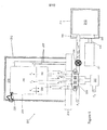
図2は、図1の燃料電池装置をさらに説明し、流体接続と熱回収器34の配置について強調している。一体型燃料電池装置のハウジング18は、その外観においてのみ示し、燃料改質器10、および後部ガスバーナー(または触媒コンバーター)12の提案された配置を示すサブ領域を有している。燃料と空気の混合物は、入口管60に沿って直接に燃料改質器10に入る。その後、改質された燃料は、内部経路チャンネルによって燃料電池のアノードのそばを通過し、最終的には後部ガスバーナー12の領域に達する。燃料電池のカソードのための空気は、入口管62を通じて入り、制御されたルートを介して内部に流れ、燃料電池のカソードに至る。空気流と燃料流の両方は、後部ガスバーナー12において最終的に再結合し、酸化の残りの熱をいくらかでも抽出し、その後出口管64から熱いゾーンを出る。
FIG. 2 further illustrates the fuel cell apparatus of FIG. 1 and emphasizes the fluid connection and arrangement of the
入口管および出口管は、ハウジングと冷たい外壁との間の領域をブリッジし、低熱伝導率に設計されるべきである。例として、このような管は、国際公開公報WO03/013729に記載されているように、窒化珪素で構成されてよく、好ましくは5ミクロン以下の壁厚を有する。あるいは、管は、石英ガラスキャピラリーから作製されてもよい。例えば、ガラスキャピラリーは、1mm外径で、125ミクロンしかない壁厚で入手可能である。このようなキャピラリーに沿って伝達されるであろう熱出力は、5mm長で800℃に渡る温度勾配であれば、0.05ワットのみである。 The inlet and outlet tubes should be designed for low thermal conductivity, bridging the area between the housing and the cold outer wall. By way of example, such a tube may be composed of silicon nitride, preferably having a wall thickness of 5 microns or less, as described in WO 03/013729. Alternatively, the tube may be made from a quartz glass capillary. For example, glass capillaries are available with 1 mm outer diameter and wall thickness of only 125 microns. The heat output that would be transferred along such a capillary is only 0.05 Watts for a 5 mm long temperature gradient over 800 ° C.
ハウジング内における燃料改質器と後部ガスバーナーの別の配置が本発明の範囲内であることは、当業者によって認識されるであろう。同様に、図2に示したものとは、別の配置の入口管と出口側、および異なる数の入口管と出口管が可能である。例えば、比較的長い燃料電池装置に対しては、外部フロー調節システムから直接に燃料改質器への、燃料と空気の独立した流れを送達するため、4番目の管を追加することが好適かもしれない。2つの独立した空気のソースをカソード領域へ提供し、燃料電池装置内で、および/または燃料電池膜の局所領域における燃料電池電圧を制御するための手段として、流体圧低下がさらに効率的に管理されることも好適かもしれない。また、特定の実施形態においては、同芯管も使用されてよい。 Those skilled in the art will recognize that alternative arrangements of the fuel reformer and rear gas burner within the housing are within the scope of the present invention. Similarly, different arrangements of inlet and outlet sides and different numbers of inlet and outlet pipes than those shown in FIG. 2 are possible. For example, for relatively long fuel cell devices, it may be preferable to add a fourth tube to deliver an independent flow of fuel and air from the external flow control system directly to the fuel reformer. unknown. Fluid pressure drop is more efficiently managed as a means to provide two independent sources of air to the cathode region and to control the fuel cell voltage within the fuel cell device and / or in the local region of the fuel cell membrane It may also be suitable to be done. In certain embodiments, concentric tubes may also be used.
熱回収器
図2を再度参照すると、2つのバーとして示す熱回収器34は、熱回収のための手段であり、流体管アセンブリの一体化部分として構築されてもよい。熱回収器は、典型的にはシリコンのような熱伝導材で作製され、出口管64を通過する排出ガスの熱が吸収されて、入口管60と62の流入するガス流に移動され得る。
Heat Recovery Unit Referring again to FIG. 2, the
図1に示すように、断熱空間28内に熱回収器34を設置することで改善された性能が可能である。この位置において、一体型燃料電池装置と外壁との間の中間で、熱回収器のさまざまな内部温度が維持され得る。既存の断熱空間内に熱回収器を設置することで、熱回収器の周囲で別の断熱材が削除されるため、全体のシステムサイズも削減される。さらに、熱回収器の熱勾配を、一体型燃料電池装置と外壁との間の既存の熱勾配と合わせることで、熱回収器からの熱損失を減少させる。これは、熱回収器の所与の部分と隣接する断熱空間の間に、あったとしても温度差がほとんど無いからである。
As shown in FIG. 1, improved performance is possible by installing a
図2に示す並列管配置以外にも熱回収器の種々の手段が可能である。例えば、管中管(tube−in−tube)対向流配置が適切であり、または、機械加工や成型されたマイクロチャンネルによって対向流が可能に形成された薄金属シートのスタックである。熱回収器の物理的配置が、燃料電池装置の等温の(「熱い」)ゾーンと冷たい外壁との間の中間領域内にある限り、多くの他の仕組みが本発明の範囲内に該当する。 Various means of the heat recovery unit are possible in addition to the parallel tube arrangement shown in FIG. For example, a tube-in-tube counter-flow arrangement is suitable, or a stack of thin metal sheets formed to allow counter-flow by machined or molded microchannels. Many other schemes fall within the scope of the present invention as long as the physical arrangement of the heat recovery device is in the intermediate region between the isothermal ("hot") zone of the fuel cell device and the cold outer wall.
低熱伝導流体接続
発明の全体的目標は、ハウジングからの全熱放散を管理することである。1つの特定の要素において、流体入口管と流体出口管の長さに沿った熱の固体伝導の要因となる、管を介する熱損失(Q管)を管理するため、管を介する熱損失が、a)管壁材の熱伝導率、b)管に沿った温度降下、およびc)管壁材の断面積、の積を、d)管の長さ、で除算することから計算され得る。
The overall goal of the low heat transfer fluid connection invention is to manage the total heat dissipation from the housing. In one particular element, to manage the heat loss through the tubes (Q tubes ), which contributes to the solid conduction of heat along the length of the fluid inlet and fluid outlet tubes, the heat loss through the tubes is: It can be calculated by dividing the product of a) the thermal conductivity of the tube wall material, b) the temperature drop along the tube, and c) the cross-sectional area of the tube wall material by d) the length of the tube.
小型燃料電池装置システムについては、流体管から許容される最大熱損失は、システム効率を改善するために決定される。その熱損失(Q管)は、管あたり0.1ワット未満に、好ましくは管あたり0.05ワット未満に、望ましくは維持される。この熱損失値は当業者に公知の実施形態をかなり下回るが、流体接続管がこの臨界値を下回る熱損失で構築されるとき、システム効率は劇的に改善する。表2は、典型的な既知の管材料および設計ならびに臨界熱損失条件を満足するように構築されている本実施形態と共に使用するのに適する代表的な管(実施形態3および4)を示す。

流体接続管材の比較(出力損失Qは、700℃の全体の温度低下を仮定する。)
For small fuel cell device systems, the maximum heat loss allowed from the fluid line is determined to improve system efficiency. The heat loss (Q tube ) is desirably maintained at less than 0.1 watts per tube, preferably less than 0.05 watts per tube. Although this heat loss value is well below embodiments known to those skilled in the art, system efficiency improves dramatically when the fluid connection tube is built with heat loss below this critical value. Table 2 shows typical known tube materials and designs and representative tubes (embodiments 3 and 4) suitable for use with this embodiment that are constructed to meet critical heat loss conditions.
Comparison of fluid connection pipes (output loss Q is assumed to be 700 ° C. overall temperature drop)
33%効率、2ワット燃料電池装置発電機において、燃料電池装置は、6ワット相当の燃料を燃焼するものと考えられ、管あたり0.1ワットの熱損失は全消費パワーの5%のみを表すものである。5〜30ワットの大型の燃料電池装置については、増加した量の流体流を扱うため、さらに多くの管か、さらに大きな断面積を有する管が必要かもしれない。各管の熱損失を0.5ワット未満に、好ましくは0.1ワット未満に維持することによって、機器中で燃料として燃焼された全パワーのうち、流体接続による熱損失の割合は、10%以下、および好ましくは5%以下に維持することができる。 In a 33% efficiency, 2 watt fuel cell generator generator, the fuel cell device is considered to burn 6 watts of fuel, and a 0.1 watt heat loss per tube represents only 5% of the total power consumed. Is. For large 5-30 watt fuel cell devices, more tubes or tubes with a larger cross-sectional area may be required to handle the increased amount of fluid flow. By maintaining the heat loss of each tube below 0.5 watts, preferably below 0.1 watts, of the total power burned as fuel in the equipment, the percentage of heat loss due to fluid connections is 10% Or less, and preferably 5% or less.
低熱伝導電気接続
発明の別の全体の目標は、電気接続に沿って固体伝導として表される熱損失を削減することである。好適な実施形態において、電線あたりの熱損失の値は、0.5ワット未満であるべきであり、さらに好ましくは約0.1ワット未満である。しかし、線あたり0.1ワット以下の電気的損失は、より高い抵抗とより細い径の線接続の使用を必要とする。表3は、線径、線抵抗、および既知の線についての損失の間の相関と、発明において有用なもの(実施形態3および4)とを示す。線抵抗と、線に沿った熱出力損失との間の逆相関に注意すること。これは金属導電体について典型的である。既知の燃料電池システムについて、スタック出力が典型的に100ワットを超えており、放散される全体の熱が300ワットを超過していると、線あたり1ワットの損失は過剰ではない。20ワット以下の定格の燃料電池装置について、線による熱損失の削減が望まれる。熱損失を制御するためこの発明に採用された方法は、電気抵抗が0.1オームを超過し、好ましくは0.5オームを超過する電気的接続を選択することである。
電気接続線の比較。(線の長さに沿った温度低下は、700℃であると仮定する。)
Another overall goal of the low heat conduction electrical connection invention is to reduce heat loss expressed as solid conduction along the electrical connection. In preferred embodiments, the value of heat loss per wire should be less than 0.5 watts, more preferably less than about 0.1 watts. However, an electrical loss of less than 0.1 watt per line requires the use of higher resistance and thinner diameter wire connections. Table 3 shows the correlation between wire diameter, wire resistance, and loss for known wires and those useful in the invention (embodiments 3 and 4). Note the inverse correlation between line resistance and heat output loss along the line. This is typical for metal conductors. For known fuel cell systems, if the stack power is typically over 100 watts and the total heat dissipated is over 300 watts, the 1 watt loss per line is not excessive. For fuel cell devices rated at 20 watts or less, it is desirable to reduce heat loss due to wires. The method employed in this invention to control heat loss is to select an electrical connection whose electrical resistance exceeds 0.1 ohms, and preferably exceeds 0.5 ohms.
Comparison of electrical connection lines. (It is assumed that the temperature drop along the length of the line is 700 ° C.)
表3から、絶縁空間をブリッジする接続線を選択する。ここで線の抵抗が0.5オームを超過することが有利である。しかし、この制約を有して効率的な燃料電池装置を達成するためには、他に、燃料電池装置動作パラメータへの変更と、燃料電池スタックの構成への変更とが必要である。例えば、接続線における抵抗による過剰な電力損失を防ぐため、出力電流は、充分低いレベルに維持されなければならない。従って、本明細書に開示の技術を使用すると、燃料電池電圧を増加することによって、電流は所与の出力レベルに低減され得る。しかし、電圧が追加されるように、個別の燃料電池を直列に接続またはスタックすることによってこの目的は過去において達成された。0.5オームを超過するコネクタワイヤを配置する本発明については、10ボルトを超える、好ましくは15ボルトを超えるスタックされた出力電圧が必要とされる。 From Table 3, a connection line that bridges the insulating space is selected. Here it is advantageous for the resistance of the wire to exceed 0.5 ohms. However, in order to achieve an efficient fuel cell device with this restriction, other changes to the fuel cell device operating parameters and changes to the configuration of the fuel cell stack are required. For example, the output current must be maintained at a sufficiently low level to prevent excessive power loss due to resistance in the connection lines. Thus, using the techniques disclosed herein, the current can be reduced to a given power level by increasing the fuel cell voltage. However, this goal has been achieved in the past by connecting or stacking individual fuel cells in series so that voltage is added. For the present invention to place connector wires that exceed 0.5 ohms, stacked output voltages greater than 10 volts, preferably greater than 15 volts are required.
電圧スタッキングについての1つの方法は、面内スタッキング配置であり、この場合、燃料電池膜層は、1つのセルのアノードがそのすぐ上のセルのカソードに、電気的に接触するように垂直にスタックされる。燃料電池スタックに対する10ボルトの出力要求であれば、12から20の燃料電池膜層が垂直スタックに組み立てられることが必要である。しかし、図1に示した実施形態は、体積効率のため2つの膜層のみを示す。それでもなお、本明細書に開示の面内スタッキングコンセプトを使用して有利な出力電圧が可能である。 One method for voltage stacking is an in-plane stacking arrangement in which the fuel cell membrane layer is stacked vertically so that the anode of one cell is in electrical contact with the cathode of the cell immediately above it. Is done. For a 10 volt output requirement for a fuel cell stack, 12 to 20 fuel cell membrane layers need to be assembled into a vertical stack. However, the embodiment shown in FIG. 1 shows only two membrane layers for volume efficiency. Nevertheless, advantageous output voltages are possible using the in-plane stacking concept disclosed herein.
図3は、面内スタッキングのコンセプトを示す。面内スタッキングは、アノード、カソード、および電解質を、直列型の電圧接続が作製され得るようにパターン付けする能力が必要である。図3において、燃料電池電解質23Aのアノード22において、隣接する燃料電池電解質23Bの背後に配置されているカソード24に電気的に接触することが可能となる。相互接続材25は、アノード22とカソード24の間で低抵抗電気接続を可能とする。
図1に示す構造的支持部材も、アノードまたはカソードのいずれかを離散した領域へパターン付けするために有用である。
FIG. 3 shows the concept of in-plane stacking. In-plane stacking requires the ability to pattern the anode, cathode, and electrolyte so that series voltage connections can be made. In FIG. 3, the
The structural support member shown in FIG. 1 is also useful for patterning either the anode or the cathode into discrete regions.
図1に示す一体型燃料電池装置の小型性と、電気接続が細いゲージワイヤ(直径約100ミクロン未満)で達成される目標を考えると、嵩張るネジや圧着端子を使用することなくコネクタワイヤを取り付けるための信頼できる方法を提供することも望ましい。1つの実施形態において、細いゲージワイヤは、一体型燃料電池装置と外壁におけるコネクタ片との両方に、高温ろう付け合金によって、または好ましくは熱機械接合(thermo−mechanical bond)のような接合方法によって取り付けられるべきである。 Considering the small size of the integrated fuel cell device shown in FIG. 1 and the goal that electrical connection can be achieved with a thin gauge wire (less than about 100 microns in diameter), a connector wire can be attached without using bulky screws or crimp terminals It would also be desirable to provide a reliable method for this. In one embodiment, the thin gauge wire is bonded to both the integral fuel cell device and the connector piece on the outer wall by a high temperature brazing alloy or preferably by a bonding method such as a thermo-mechanical bond. Should be mounted.
一体型燃料電池装置の等温性
燃料改質器、燃料電池および後部ガスバーナーの全ての機能が、単一のハウジング内へ最小の表面積を有して一体化するとき、固体型燃料電池装置の効率は改善する。また、構成要素間で、熱の効率的な分配または熱エネルギーの共有を可能とする充分な熱伝導率を有してハウジングが設計されるとき、効率は改善する。特に、全体の効率を改善する補足の熱を共有するように後部ガスバーナーが使用されてよい。従って、後部ガスバーナーで生成された熱エネルギーは、燃料電池装置内でさらに高くさらに効率の良い動作温度を維持する。このようにして、装置を加熱したりまたは冷却したりする際の熱的ストレスとコストが削減される。
The efficiency of a solid fuel cell device when all the functions of the isothermal fuel reformer, fuel cell and rear gas burner of the integrated fuel cell device are integrated with a minimum surface area into a single housing Will improve. Efficiency also improves when the housing is designed with sufficient thermal conductivity to allow efficient distribution of heat or sharing of thermal energy between components. In particular, a rear gas burner may be used to share supplemental heat that improves overall efficiency. Accordingly, the thermal energy generated by the rear gas burner maintains a higher and more efficient operating temperature within the fuel cell device. In this way, thermal stresses and costs when heating or cooling the device are reduced.
さらに、改善された燃料電池効率は、平衡電気化学電位に近いさらに高電圧で燃料電池を動作させることにより可能である。このような動作条件は、比較的低い燃料電池電圧で動作する場合に比べて、より少ない廃熱の生成を示唆する。動作温度を維持するために必要な熱エネルギーの量は、後部ガスバーナーにおいて、あまり利用されていない燃料の燃焼から熱を抽出することで達成可能である。 Furthermore, improved fuel cell efficiency is possible by operating the fuel cell at higher voltages close to the equilibrium electrochemical potential. Such operating conditions suggest less waste heat generation compared to operation at relatively low fuel cell voltages. The amount of thermal energy required to maintain the operating temperature can be achieved by extracting heat from the less utilized fuel combustion in the rear gas burner.
充分な熱伝導率と燃料電池装置内構成要素間でのほぼ等温動作を維持するために、いくつかの方法が採用され得る。基板材料として使用されるシリコンは、高温における優れた熱電導体である。ガラスまたはセラミック基板は、得られる壁厚が実質的に100ミクロンを超過し、好ましくは300ミクロンを超過するという条件では、熱伝導率に基づく適切な材料選択である。ガラス基板の熱伝導率は、ハウジングの外面のような通電されていない領域を覆う金属薄膜の堆積によって高められる。候補の熱伝導金属コーティングには、クロム、金、および白金が含まれる。 Several methods can be employed to maintain sufficient thermal conductivity and nearly isothermal operation between the components within the fuel cell device. Silicon used as a substrate material is an excellent thermoconductor at high temperatures. Glass or ceramic substrates are a suitable material choice based on thermal conductivity, provided that the resulting wall thickness is substantially greater than 100 microns, and preferably greater than 300 microns. The thermal conductivity of the glass substrate is enhanced by the deposition of a thin metal film that covers a non-energized region such as the outer surface of the housing. Candidate thermally conductive metal coatings include chromium, gold, and platinum.
システムの実質的等温動作を可能とする手段として、一体型ハウジングを設計することが役立つ。一体型ハウジングは、分離した構成要素(燃料改質器、後部ガスバーナー、および燃料電池膜)が、そのいずれかのペアの間で少なくとも1つの共通の構造的壁を共有するようにしている。この壁は、ハウジングの外壁であってよく、または、形成された内壁であってもよく、例えば個別の基板の接合を介する。 It is helpful to design an integral housing as a means of enabling substantially isothermal operation of the system. The integral housing allows separate components (fuel reformer, rear gas burner, and fuel cell membrane) to share at least one common structural wall between any pair thereof. This wall may be the outer wall of the housing, or it may be a formed inner wall, for example through the joining of individual substrates.
構造的壁を共有することで、または充分に熱伝導率を有する基板を提供することで、動作中、構成要素間で、150℃未満までの、好ましくは50℃未満の任意の温度差を維持することができる。 Maintaining any temperature difference between components up to less than 150 ° C, preferably less than 50 ° C during operation by sharing structural walls or providing a substrate with sufficient thermal conductivity can do.
出力密度
携帯型固体電解質型燃料電池装置を設計するとき、燃料エネルギーを過剰に消費をすることなく、高い運転温度を維持する適切な断熱材の最小の厚みを決定することが重要である。一体型燃料電池装置から放散するであろう熱の量は、その表面積に比例する。従って、5ワット用に設計された一体型燃料電池装置は、20ワット以上用に設計された一体型燃料電池装置に比べて、その表面の体積に対する比率が非常に高いので、効率的に断熱することは困難となる。
When designing a power density portable solid oxide fuel cell device, it is important to determine the minimum thickness of a suitable insulation that maintains a high operating temperature without consuming excessive fuel energy. The amount of heat that will be dissipated from the integrated fuel cell device is proportional to its surface area. Therefore, an integrated fuel cell device designed for 5 watts has a much higher surface to volume ratio than an integrated fuel cell device designed for more than 20 watts, so that it efficiently insulates. It becomes difficult.
一体型燃料電池装置の出力密度は、重要な設計パラメータである。特に、出力密度は、最終的効率と断熱したパッケージのサイズとに最も影響ある設計パラメータであり得る。一体型燃料電池装置の出力密度は、ワット毎立方センチメートル(W/cc)で表され、生成される電気のワット毎にどの程度表面積が露出しているかを決定する。その結果、最終パッケージサイズにおける、一体型燃料電池装置の電力密度の影響は、大きく不釣合いである。例えば、5ワットおよび1w/ccで出力を生成することができる一体型燃料電池装置は、断熱材を含めて66ccのパッケージサイズを要求するであろう。これに対して、5ワットおよび2w/ccの定格の一体型燃料電池装置は、17.8ccのみで、パッケージ内で断熱されることが可能である。従って、出力密度の2倍の増加は、熱効率を失うことなく、パッケージサイズにおける3.7倍の減少となる。(この例は、800℃の温度降下を維持し、0.04W/m−Kにおける定格のaerogel(商標)断熱材の使用を仮定する。) The power density of the integrated fuel cell device is an important design parameter. In particular, power density may be the design parameter that most affects the final efficiency and the size of the insulated package. The power density of an integrated fuel cell device is expressed in watts per cubic centimeter (W / cc) and determines how much surface area is exposed for each watt of electricity generated. As a result, the influence of the power density of the integrated fuel cell device on the final package size is largely disproportionate. For example, an integrated fuel cell device capable of producing output at 5 watts and 1 w / cc would require a package size of 66 cc including insulation. In contrast, an integrated fuel cell device rated at 5 watts and 2 w / cc can be insulated within the package with only 17.8 cc. Thus, a two-fold increase in power density results in a 3.7-fold decrease in package size without losing thermal efficiency. (This example assumes the use of rated aerogel ™ insulation at 0.04 W / m-K, maintaining a temperature drop of 800 ° C.)
図4は、本発明の別の実施形態を示し、この場合、大型燃料電池装置105は、四つの異なる膜層を採用する。燃料電池膜114、空気または酸素経路層148、または燃料経路層147、149.150、の各層は、全体のスタックが高さ約4.8mmとなるようにいずれも約0.5mm以下の厚みである。図4は、そのハウジング内に燃料改質器110と層146の一部として構成された後部ガスバーナー112も含む。燃料経路層は、燃料を改質器から運んで各燃料電池膜を通過させ、および/または排気を各燃料電池膜を通過させた後、後部ガスバーナーに運ぶ。図4を使って、全体の一体型燃料電池装置の高さ(4.8mm)を膜層の数(4)で除算して規定される、膜層間の平均の間隔が計算され得る。従って図4の平均の膜間隔は、約1.2mmである。この場合、出力密度は、各燃料電池層の平均の出力密度(0.4W/cm2)を平均の膜間隔で除算することによって得ることができ、約3.3W/ccの出力密度という結果となる。
FIG. 4 shows another embodiment of the present invention, where the large
一体型燃料電池装置の体積の1立方センチメートルあたり約2ワットを超過する電気エネルギーを可能とする燃料電池スタックの構成が好ましい。2W/ccを超えて生成する方法で、所与の燃料電池スタックを動作することも望ましい。燃料電池によって生成された出力は、電圧を変更することによって、および燃料電池の温度を変更することによって、制御されることが可能である。比較的大きな燃料電池は、化学エネルギーから電気エネルギーへの変換の効率を高めるため、典型的には最大出力以上の電圧で動作している。1W/cc、1.5W/cc、または好ましくは2W/ccを超える出力密度が本発明に含まれる。 A fuel cell stack configuration that allows greater than about 2 watts of electrical energy per cubic centimeter of volume of the integrated fuel cell device is preferred. It is also desirable to operate a given fuel cell stack in a manner that produces over 2 W / cc. The output generated by the fuel cell can be controlled by changing the voltage and by changing the temperature of the fuel cell. Larger fuel cells typically operate at voltages above their maximum output in order to increase the efficiency of conversion from chemical energy to electrical energy. Power densities exceeding 1 W / cc, 1.5 W / cc, or preferably 2 W / cc are included in the present invention.
約2W/cc未満に出力を低下するレベルへ電圧を高めることは、小型システムにおいて実際には全体のシステム効率を低下させる。これは、必要な温度を維持するためには不十分な熱しか生成されないからである。触媒コンバーターまたは後部ガスバーナーを一体化することで、燃料電池出力をいくぶん低下させることが可能である。 Increasing the voltage to a level that reduces the output to less than about 2 W / cc actually reduces the overall system efficiency in small systems. This is because only insufficient heat is generated to maintain the required temperature. By integrating the catalytic converter or the rear gas burner, it is possible to reduce the fuel cell output somewhat.
1つの主要な出力密度の改善は、膜間の垂直間隔を近づけることで達成される。既存技術における膜間の平均間隔は、2.5〜4mmの範囲である一方、本発明に典型的な膜間の平均的間隔は、約1.5mm未満であり、1.0mmの値の小ささに近づいている。膜間がより近づく利点は、2つの有利な構造的特徴から得られる。すなわち、a)機械的に頑丈な複合膜設計の使用、およびb)面内スタッキング(in−plane stacking)の使用により可能である構造的に簡単な流路層の使用、である。この実施形態において、有利な使用は、面内燃料電池スタッキングの構築でもなされる。面内燃料電池スタッキングによって、多くの構造的利点が可能となり、これらが一緒に作用して膜間の間隔を減少させ、かつ2W/ccを優に超える値に出力密度を増加させる。 One major power density improvement is achieved by reducing the vertical spacing between the films. While the average spacing between membranes in existing technology is in the range of 2.5-4 mm, the average spacing between membranes typical for the present invention is less than about 1.5 mm, with a small value of 1.0 mm. Approaching the size. The advantage of closer membrane spacing results from two advantageous structural features. That is, a) the use of a mechanically robust composite membrane design, and b) the use of a structurally simple channel layer that is possible through the use of in-plane stacking. In this embodiment, an advantageous use is also made in the construction of in-plane fuel cell stacking. In-plane fuel cell stacking allows a number of structural advantages that work together to reduce the distance between the membranes and increase the power density to values well above 2 W / cc.
複合膜構造の使用は、共有の国際公開公報WO2005/030376号に記載されてきた。簡単には、複合膜構造は、強い構造的支持膜と、薄い(<2μm)YSZ膜層との組み合わせを可能とする。このような構造は、過剰な基板厚みを必要とすることなく熱的サイクルの応力に耐える強度を有し、約0.5mm以下のシリコンウェハー厚みを使用して達成されることが可能である。同様の複合構造は、熱膨張係数にかかわらず、高密度のセラミック基板、例えばAl2O3材料から、上記に特定される特許出願にレイアウトされた設計規則に従う程度であれば構築されることが可能である。 The use of a composite membrane structure has been described in the shared international publication WO 2005/030376. Briefly, the composite membrane structure allows a combination of a strong structural support membrane and a thin (<2 μm) YSZ membrane layer. Such a structure has the strength to withstand thermal cycle stress without requiring excessive substrate thickness and can be achieved using a silicon wafer thickness of about 0.5 mm or less. Similar composite structures can be constructed from high-density ceramic substrates, such as Al 2 O 3 material, to the extent that it follows the design rules laid out in the above-identified patent application, regardless of the coefficient of thermal expansion. Is possible.
公知の層製作技術において、燃料と空気との間でガス流を分離するため、気体不透過性の双極性プレートが必要である。垂直の平面スタックは、1つの膜層のアノードから隣接する層のカソードへの電気的接触を必要とする。しかし、アノードを通過する燃料は、カソード上を流れる空気と混合してはならない。従って導電性双極性プレートが典型的に採用され、これは、層間の電気的接続のみではなく、アノードに至る燃料の経路、カソードに至る空気の経路、およびガス流間の密封した分離にも影響する。 In known layer fabrication techniques, a gas impermeable bipolar plate is required to separate the gas stream between fuel and air. A vertical planar stack requires electrical contact from the anode of one membrane layer to the cathode of an adjacent layer. However, fuel passing through the anode must not mix with air flowing over the cathode. Thus, conductive bipolar plates are typically employed, which affect not only the electrical connection between the layers, but also the fuel path to the anode, the air path to the cathode, and the sealed separation between the gas streams. To do.
図1に戻って、燃料電池膜14のカソードが燃料電池膜16のカソードに直接面するので、流路層においてそのようなガス分離は要求されない。両方の膜層は、同一のガス流を共有し、これら2つの燃料電池層間において電気的接続は必要とされない。従って流路層の設計が簡単化されて、0.3〜0.5mmの範囲の厚みを有する極端に薄い流路層が可能である。
Returning to FIG. 1, since the cathode of the
図5は、1つのこのような流路層を示し、図4に示す4層燃料電池スタックに適合する形状を有している。開口180は、スタックの一層から上下の層への燃料の垂直通過を提供する。チャンネル182は、カソード上の空気の流れを提供する。流路層148が2つのカソードに面する層を分離するという程度で、ごく簡単なリブ付の構造が必要であり、これにより、両方の構造的頑丈さをスタックに追加し、かつ、全カソード面上に充分な空気の分配を提供する。
FIG. 5 shows one such channel layer and has a shape that matches the four-layer fuel cell stack shown in FIG. The
流路層は、シリコンのような硬質材で構成されてよい。この実施形態におけるシリコンの選択は、全膜層と流路層の間で構造材を整合する別の利点を有する。このようにして、このような2つの構造材間の異なる熱膨張係数に関連する応力を避けることができる。 The channel layer may be made of a hard material such as silicon. The selection of silicon in this embodiment has another advantage of matching the structural material between the entire membrane layer and the flow path layer. In this way, stresses associated with different coefficients of thermal expansion between two such structural materials can be avoided.
流路層は、機械加工されるかまたは金属材から打ち抜かれ得る。しかし、流路層の熱膨張係数は、膜層における構造材のものと実質的に類似であることが維持されなければならない。薄い金属性流路層は、シリコンから構築された経路層ほど頑丈ではないが、膜層用に採用されたシリコンまたは他のセラミック材料は、充分すぎる頑丈さを提供し、熱サイクルの応力に耐える充分な強度を全体のスタックに提供する。 The channel layer can be machined or stamped from a metal material. However, the thermal expansion coefficient of the channel layer must be maintained to be substantially similar to that of the structural material in the membrane layer. Thin metallic channel layers are not as robust as path layers constructed from silicon, but silicon or other ceramic materials employed for membrane layers provide sufficient robustness and withstand thermal cycling stresses Provide sufficient strength for the entire stack.
熱生成/断熱
さらに、約2W/ccを超える電力出力の維持に加えて、生成された熱が2W/ccを超えて維持される場合、システム性能とサイズも改善される。小型サイズにおける表面積の急速な増加のために、装置の動作温度を維持するため、充分に高い熱密度を維持することが望ましい。燃料電池装置単独で充分な熱を生成しない場合、1立方センチメートルあたり2Wの熱を超過して維持するためには、後部ガスバーナーを使用して余剰の燃料を燃焼させることが、効率的な機器の運転のために有利である。機器が、1立方センチメートルあたり2Wの熱を超過して運転されるであろうことを確実とすることで、断熱材の厚みを最小化することができ、これにより、既存のバッテリーと競合する機器を製造することができる。
Heat generation / insulation Furthermore, in addition to maintaining power output above about 2 W / cc, system performance and size are also improved if the heat generated is maintained above 2 W / cc. Due to the rapid increase in surface area in small sizes, it is desirable to maintain a sufficiently high heat density to maintain the operating temperature of the device. If the fuel cell device alone does not generate enough heat, in order to maintain over 2W of heat per cubic centimeter, it is efficient to burn excess fuel using a rear gas burner. It is advantageous for driving. By ensuring that the equipment will be operated in excess of 2W of heat per cubic centimeter, the thickness of the insulation can be minimized, thereby competing with existing batteries. Can be manufactured.
固体電解質型燃料電池システムにおける断熱空間の設計は、固体電解質型燃料電池の効率を改善するための別の領域である。断熱材からの伝導によって損失する廃熱の量を最小化しつつ、外側パッケージとその周囲から高温ハウジングを隔離する機能のため、繊維状セラミックスまたは多孔質セラミックスが利用されてきた。例えば、低熱伝導率を有し、かつ800℃の運転中に安定した0.04W/m−Kの低さである、エアロゲル材が利用可能である。 The design of the insulation space in the solid oxide fuel cell system is another area for improving the efficiency of the solid oxide fuel cell. Fibrous ceramics or porous ceramics have been used for the function of isolating the high temperature housing from the outer package and its surroundings while minimizing the amount of waste heat lost due to conduction from the insulation. For example, an airgel material having low thermal conductivity and having a low value of 0.04 W / mK that is stable during operation at 800 ° C. can be used.
おそらく最も空間効率的な断熱は、特に小型パッケージにおいては真空断熱である。これにより、外壁と、ハウジング内に一体化された内容物を所望の温度に維持する断熱空間とを有する魔法瓶として、燃料電池装置の各部が機能することを可能とする。断熱空間中の全体のガス圧を100mtorr未満に、好ましくは20mtorr未満に、さらに好ましくは10mtorr未満に維持することで、ガス相を通じたハウジングから出る伝導による、何らかの熱損失を実質的に除去することが可能である。外壁によって区切られた断熱空間中に、ガス放出口から真空ポンプ用いた真空引きによって、あるいは、真空引きされた雰囲気中で外壁の要素を共にシールする処理を実施することで、部分的真空が形成されてもよい。 Probably the most space efficient insulation is vacuum insulation, especially in small packages. Thereby, each part of a fuel cell apparatus is enabled to function as a thermos which has an outer wall and the heat insulation space which maintains the content integrated in the housing at desired temperature. Maintaining the overall gas pressure in the insulated space below 100 mtorr, preferably below 20 mtorr, more preferably below 10 mtorr, to substantially eliminate any heat loss due to conduction out of the housing through the gas phase. Is possible. A partial vacuum is formed in the heat-insulated space separated by the outer wall by vacuuming from the gas discharge port using a vacuum pump or by sealing the elements of the outer wall together in a vacuumed atmosphere. May be.
真空パッケージの実施形態を利用するとき、エアロゲルのような比較的厚い固体断熱材の使用を止めるとき、ハウジングからの新たなタイプの熱損失が、赤外放射による熱損失の形態で問題となる。ハウジングの表面から放射する赤外放射は、図1に示した断熱パッケージに対して、事実上、主要な熱損失メカニズムとなり得る。 When utilizing vacuum package embodiments, a new type of heat loss from the housing becomes a problem in the form of heat loss due to infrared radiation when stopping the use of relatively thick solid insulation such as airgel. Infrared radiation emanating from the surface of the housing can in fact be a major heat loss mechanism for the insulation package shown in FIG.
放射による熱損失を削減するため、少なくも三つの方法がある。そのうちのいずれか単独が、または組み合わせて使用され得る。これらは、図1に戻って確認することができる。第1に、一体型燃料電池装置の外面に反射コーティングが塗布され、これにより、赤外放射率と熱い面からの出力損失を削減する。第2に、赤外放射を一体型燃料電池装置に戻す目的のため、真空の外壁30の内面に沿って放射反射体40が設置されてもよい。この放射反射体は、外壁30の内面に堆積された金属製コーティングによって、または真空壁の内面に機械的に取り付けられる金属製もしくは赤外反射性材によって、構築され得る。さらに、一連の並行する赤外反射体が、外壁の熱い面と冷たい面との間に設置されてもよい。
There are at least three ways to reduce heat loss due to radiation. Any one of them can be used alone or in combination. These can be confirmed by returning to FIG. First, a reflective coating is applied to the outer surface of the integrated fuel cell device, thereby reducing infrared emissivity and power loss from the hot surface. Second, for the purpose of returning infrared radiation back to the integrated fuel cell device, a
燃料電池装置調整、モニタリング、および安全性
上述のように燃料改質器、燃料電池および後部ガスバーナーを実質的に等温ゾーン内に一体化することで、燃料電池装置の効率を改善し、好適なバッテリー代替装置であることを可能とする。バッテリー代替のエネルギー密度が増加することで商品価値を改善しても、大量の化学エネルギーおよび熱エネルギーを小さい体積に局所化することで、燃焼、爆発、および/または有害化学物質の放出が制御できなくなる可能性が高くなる。本明細書に開示の多くの装置は、携帯電話バッテリー代替等、消費者が使用するのに好適であるため、燃料電池装置に、安全機構と装置監視機構を一体化することが所望されている。
Fuel cell device adjustment, monitoring, and safety As mentioned above, the fuel reformer, fuel cell and rear gas burner are integrated into a substantially isothermal zone to improve the efficiency of the fuel cell device and It makes it possible to be a battery replacement device. Even if the energy density of battery alternatives increases and commercial value improves, localizing large amounts of chemical and thermal energy to a small volume can control combustion, explosion, and / or release of hazardous chemicals. The possibility of disappearing is increased. Since many devices disclosed herein are suitable for consumer use, such as cell phone battery replacement, it is desirable to integrate a safety mechanism and a device monitoring mechanism into a fuel cell device. .
上述した実施形態の説明において常に明確に強調しているわけではないが、前に本明細書に開示した発明の多くの構造的局面および化学的フローの局面によって、燃料電池装置の安全な運転が本来的に可能となる。例えば、上述の断熱空間は、熱を閉じ込めることで、等温ゾーンにおけるエネルギー密度を高める一方で、断熱空間は、機器のユーザーを過剰な熱から遮断する。同時に、断熱空間は、何らかの制御されない燃焼を停止する補足ゾーンとして作用し、断熱空間が破れたり他に突き通された場合には、燃料転換反応を停止するための手段として作用することができる。このような機構と他の安全機構を以下に詳細に記載する。 Although not always clearly emphasized in the description of the above-described embodiments, the many structural and chemical flow aspects of the invention previously disclosed herein provide for safe operation of the fuel cell device. Essentially possible. For example, the adiabatic space described above confines heat to increase the energy density in the isothermal zone, while the adiabatic space shields equipment users from excessive heat. At the same time, the adiabatic space can act as a supplemental zone to stop any uncontrolled combustion, and can act as a means to stop the fuel conversion reaction if the adiabatic space is breached or otherwise pierced. Such mechanisms and other safety mechanisms are described in detail below.
一般に、燃料電池装置、特に携帯型固体電解質型燃料電池装置の安全性を改善するための多数の設計戦略がある。しかし、組織上の目的のため、安全機構は、二つの広いカテゴリーにグループ化することができ、さまざまな実施形態は、両方のカテゴリーに置かれる機構を含むことができる点に注意すべきである。第1に、断熱空間の熱を閉じ込める利点等の受動的設計構造および方法がある。受動的安全機構の中には、背景において絶え間なく動作し、装置の変化に対して直接的な起動の必要がなく応答するものもある。例えば、燃焼伝搬を制御する燃料電池構成の設計的局面は、別の受動的安全機構を意味する。 In general, there are a number of design strategies to improve the safety of fuel cell devices, particularly portable solid oxide fuel cell devices. However, it should be noted that for organizational purposes, safety mechanisms can be grouped into two broad categories and various embodiments can include mechanisms that are placed in both categories. . First, there are passive design structures and methods, such as the advantage of confining heat in the insulation space . Some passive safety mechanisms operate continuously in the background and respond to device changes without the need for direct activation. For example, a design aspect of a fuel cell configuration that controls combustion propagation represents another passive safety mechanism.
第2のカテゴリーの安全機構には、能動的方法と装置が含まれる。代表的な能動的安全機構は、何らかのイベントに応答して装置動作を終了させる電子制御システムである。導管が閉鎖された場合にアラームし、アラームに応答して燃焼終了指示を適切に開始するセンサーなどである。一般に、制御システム/センサーシステムは、能動的安全機構カテゴリーに該当する。 The second category of safety mechanisms includes active methods and devices. A typical active safety mechanism is an electronic control system that terminates device operation in response to some event. For example, a sensor that alarms when the conduit is closed and appropriately initiates a combustion end instruction in response to the alarm. In general, control / sensor systems fall into the active safety mechanism category.
再び、用語、受動的および能動的が使用されるが、組織的目的のために使用され、詳細な説明および特許請求の範囲を限定する意図ではないことが理解される。従って、能動的または自動的として記載されていても、さまざまな安全機構は、能動的要素と受動的要素の両方を制限なく含むことができる。 Again, the terms passive and active are used, but it is understood that they are used for organizational purposes and are not intended to limit the detailed description and claims. Thus, various safety mechanisms, whether described as active or automatic, can include both active and passive elements without limitation.
それぞれの安全機構をより詳細に記載する前に、本明細書に開示された燃料電池装置に一体化され得る、異なる能動的機器および受動的機器ならびに方法の実施形態を導入することが有用であろう。このような異なる機構の組み合わせ、および本明細書に開示の実施形態が可能であるので、広い範囲の燃料電池装置が当業者によって製作されることが可能である。 Before describing each safety mechanism in more detail, it is useful to introduce embodiments of different active and passive devices and methods that can be integrated into the fuel cell apparatus disclosed herein. Let's go. Because such different combinations of mechanisms and embodiments disclosed herein are possible, a wide range of fuel cell devices can be fabricated by those skilled in the art.
受動的安全機構の中には、断熱空間および他の形態の機器断熱材、導管径を調節して揮発性物質の放出を制限すること、構造材の選択により機器内の熱エネルギーレベルを調節すること、燃料改質器と後部ガスバーナーのような機器構成要素を、燃料転換反応を制御する自己調節温度レベルが可能となるように編成すること、種々の流れ(flow stream)および導管の径のような各種機器形状を調節して燃焼伝搬を制御すること、後部ガスバーナーのような機器構成要素を一体化して、揮発性燃料および/または燃料転換副産物を予反応することにより実質的に不揮発性の排気を提供すること、が含まれるものもある。 Some passive safety mechanisms include insulation spaces and other forms of equipment insulation, adjusting conduit diameter to limit volatile emissions, and adjusting the thermal energy level in the equipment through the choice of structure. Organizing equipment components such as fuel reformers and rear gas burners to allow a self-regulating temperature level to control the fuel conversion reaction, various flow streams and conduit diameters To control combustion propagation by adjusting various equipment shapes such as, and by integrating equipment components such as a rear gas burner to pre-react with volatile fuel and / or fuel conversion by-products Some of these include providing sexual exhaust.
次に、能動的安全機構の中には、機械式および/または電子式センサーを一体化して、燃料電池装置およびそのサブシステムの動作をモニターすること、閉止弁のような制御要素を使用して、アラームに応答して機器動作を停止すること、センサーと制御要素を組み込むシステムを制御して、安全ではない機器動作を防ぐこと、燃料電池装置と共に使用する所与の燃料源の適合性を確認する認証機器、ならびに燃料電池装置およびその構成要素の識別、認証、制御、モニタリング、および動作を提供するための各種回路が含まれるものもある。 Next, in the active safety mechanism, mechanical and / or electronic sensors are integrated to monitor the operation of the fuel cell device and its subsystems, using control elements such as shut-off valves. , Stop equipment operation in response to alarms, control systems incorporating sensors and control elements to prevent unsafe equipment operation, and confirm the suitability of a given fuel source for use with a fuel cell system Some of the authentication devices include various circuits for providing identification, authentication, control, monitoring, and operation of the fuel cell device and its components.
従って、何らかの機器の故障や異常動作の兆候が、機器の構成要素の全部または一部の停止をトリガーするようなフェールセーフ動作を提供する機構を発明はさらに含む。このため、エネルギーの放出に先立って機器動作を停止させることによって、致命的な故障にもなりかねない影響が減少する。逆に、熱からユーザーを保護する断熱フォームのような安全性を高めるための、動作中の背景において作動する受動技術も、発明の範囲内である。 Thus, the invention further includes a mechanism that provides fail-safe operation such that any indication of equipment failure or abnormal operation triggers the shutdown of all or part of the equipment components. For this reason, by stopping the operation of the device prior to the release of energy, the influence that may cause a fatal failure is reduced. Conversely, passive technologies that operate in the background during operation to increase safety, such as thermal insulation foam that protects the user from heat, are also within the scope of the invention.
図6は、種々の能動的および受動的安全機構を一体化する燃料電池装置200の実施形態の各部の概略図を示す。固体電解質型燃料電池202、燃料改質器204、および後部ガスバーナー206が、互いに流体連絡および熱連絡している。燃料電池202から生成された電気を集めるために使用される収集回路207の一部も示している。さらに、三つの構成要素全てが、ハウジング208の内部において、断熱空間210である程度区切られた等温ゾーン内で共に一体化されている。次いで、断熱空間210は、燃料電池装置200の外壁212ならびに流体マニホールドの各部およびデバイスパッケージ214によってある程度規定されている。ハウジングの体積(volume)は、約0.5ccから約100ccまでの範囲であり得る。一つの実施形態において、ハウジングの体積は、約0.5ccから約10ccまでの範囲であり得る。別の実施形態において、ハウジングの体積は、約1ccから約5ccまでの範囲であり得る。さらに、断熱空間は、約200cc以下である。
FIG. 6 shows a schematic diagram of portions of an embodiment of a
燃料215は、通常は、燃料タンクまたは燃料カートリッジ216の内部に含まれる。燃料タンク216は、さらに、燃料タンク電気接続218および燃料タンク流体接続220を含み、燃料タンク216は、燃料タンク電気接続218と連絡するか、または独立したアドレス可能機器として、認証回路222も含むことができる。空気ポンプ223も、燃料電池装置200に一体化されて、燃焼を維持するために必要な空気を等温ゾーンに供給することができる。1以上の機器制御システム224が含まれて、センサーデータおよび/または回路入力/出力を受け、およびこれらに応答して動作することができる。
種々の導管および伝導要素が使用されて、燃料、空気、燃焼副産物、ならびに燃料電池への他の化合物および燃料電池からの他の化合物、を流れやすくしている。種々の導管と輸送機構が使用されることができるので、特定の構造ではない流れまたは経路を図示することが有用である。しかし、適切に寸法決めされた導管、チャンネル、または他の流体輸送機構が使用され得て、当業者に公知の流れを含むことができる。 Various conduits and conductive elements are used to facilitate flow of fuel, air, combustion byproducts, and other compounds to and from the fuel cell. Since various conduits and transport mechanisms can be used, it is useful to illustrate a flow or path that is not a specific structure. However, appropriately sized conduits, channels, or other fluid transport mechanisms can be used and can include flows known to those skilled in the art.
このようなさまざまな流路/流れF1からF5を図6に示す。流路F1は、燃料215の機器への流れを示し、一方で、流路F2は、空気の機器への導入と流れを示す。次に、流路F3は、空気と、燃料改質器204を出た処理された燃料との混合を示す。燃料電池202における初期反応の後、化合物および反応副産物が、流路F4に沿って後部ガスバーナー206に流れる。最終的に、後部ガスバーナー206による処理の後、装置200からの熱エネルギーおよび実質的に非揮発性の排気流が、流路F5に沿って流れる。
Such various channels / flows F 1 to F 5 are shown in FIG. Channel F 1 shows the flow of
発明は、装置内で異なる反応が生じる場所を制御することで、固体電解質型燃料電池の動作を調節する技術をある程度提供する。一つの実施形態において、燃料は、燃料改質器内で反応温度T1において水素と副産物に転換される。反応温度は、反応温度範囲内である。例えば、図8の下に述べたように、ブタンについての反応温度範囲は、約200℃から約800℃までである。副産物は、排気産物と熱エネルギーに転換される。排気(exliaust)産物が水、酸素、および/または二酸化炭素のような非揮発性である場合は、排気産物は機器から流路F5に沿って流れる。 The invention provides, to some extent, a technique for regulating the operation of a solid oxide fuel cell by controlling where different reactions occur within the device. In one embodiment, the fuel is converted to hydrogen and by-products at reaction temperature T 1 in a fuel reformer. The reaction temperature is within the reaction temperature range. For example, as described below in FIG. 8, the reaction temperature range for butane is from about 200 ° C. to about 800 ° C. By-products are converted into exhaust products and heat energy. If the exhaust product is non-volatile, such as water, oxygen, and / or carbon dioxide, the exhaust product flows from the instrument along flow path F5.
流路F4に沿ってなお揮発性化合物が検出される場合は、後部ガスバーナーは、環境に入る前の排気流を、例えば実質的に完全に酸化することによってさらに浄化する。さらに副産物を転換する工程からの熱エネルギーは、反応温度範囲を維持するのに役立つ。その結果、等温ゾーン内の異なる機器構成要素が使用されることができ、入ってくる燃料を予熱し、燃料改質器の温度を維持することができる。そのため各構成要素は、制御要素として作用して燃料転換を停止したり、または開始することができる。 If volatile compounds are still detected along flow path F4, the rear gas burner further purifies the exhaust stream prior to entering the environment, for example, by substantially completely oxidizing it. Furthermore, the heat energy from the process of converting the by-products helps to maintain the reaction temperature range. As a result, different equipment components within the isothermal zone can be used to preheat incoming fuel and maintain the temperature of the fuel reformer. Thus, each component can act as a control element to stop or initiate fuel conversion.
図6に戻って、制御システム/制御回路224が使用されて、燃料タンク216の認証回路222とやり取りすることができる。一つの実施形態において、制御回路224は、また、燃料電池装置200の動作に関するデータを受け、そのデータに応答して、燃料電池装置の動作を調節する。温度センサー226、流れセンサー(単数または複数)228、圧力センサー(図示せず)、ならびに他のセンサーおよび検出器が、燃料電池装置の各種構成要素の内部または外部に一体化されて、種々の動作パラメータをモニターすることができる。電気的/機械的に制御されたフローバルブ230が、燃料導管に伴ってもよいし、または燃料カートリッジの一部であってもよい。好適なセンサーには、流体流検出器、化学検出器、圧力検出器、比較回路、電圧検出器、電流検出器、直接質量流量検出器、間接質量流量検出器、体積流検出器、差動(微分)検出器、温度検出器、放射検出器、およびこれらの組み合わせが含まれ得るが、これらに限定されない。
Returning to FIG. 6, the control system /
制御システムは、図に明示していない種々の電気接続を介して装置データを送ったり、および受けたりすることができる。従って装置は、不規則に動作し始めてユーザーにリスクを呈することがある。制御システムは、温度データ、流れデータ、圧力データ、事前設定データ、または他のデータを介して不規則性を識別することができる。これに応じて、制御回路は、フローバルブや、または燃料改質器のような他の燃料電池機器構成要素に電気信号を送って、燃料転換を停止させることができる。従って、バルブベースのシステムに対して、制御システムは、バルブを閉鎖して燃料改質器への燃料流を停止させるよう指示を出す。好適な装置データには、温度データ、流体流データ、圧力データ、放射データ、電気信号データ、電流データ、電圧データ、形状(geometric)データ、構造的安定性データ、振動データ、剪断応力(sheer stress)データ、化学組成データ、およびこれらの組み合わせが含まれ得るがこれらに限定されない。 The control system can send and receive device data via various electrical connections not explicitly shown. Thus, the device may begin to operate irregularly and present a risk to the user. The control system can identify irregularities via temperature data, flow data, pressure data, preset data, or other data. In response, the control circuit can send an electrical signal to a flow valve or other fuel cell equipment component such as a fuel reformer to stop the fuel conversion. Thus, for the valve-based system, the control system instructs the valve to close and stop the fuel flow to the fuel reformer. Suitable device data includes temperature data, fluid flow data, pressure data, radiation data, electrical signal data, current data, voltage data, geometric data, structural stability data, vibration data, shear stress. ) Data, chemical composition data, and combinations thereof, but are not limited to these.
センサー、導管、バルブ、制御、および回路は、システム内の種々の位置に配置されることができることが、当業者であれば明白であろう。例えば燃料流センサーは、図6に示す電気制御弁の下流ではなく、上流に配置されてよい。さらに、電子制御回路と各種センサー、バルブおよびポンプとの間で、種々の電気接続が図示されていないが、当業者に公知の、各種導管、半導体トレーシング、マイクロ流路、およびワイヤベースの接続で適切な接続が達成され得る。 It will be apparent to those skilled in the art that the sensors, conduits, valves, controls, and circuits can be located at various locations within the system. For example, the fuel flow sensor may be arranged upstream rather than downstream of the electric control valve shown in FIG. In addition, various electrical connections between the electronic control circuit and various sensors, valves and pumps, not shown, are known to those skilled in the art, such as various conduits, semiconductor tracing, microchannels, and wire-based connections. A suitable connection can be achieved.
当業者に公知の各種センサーが、異なる実施形態の装置に組み込まれる。特に好適なセンサーには、限定されないが、熱電対、Omega Engineering,Inc.製モデル番号P13R−001のようなシース無し細線熱電対、タイプR、0.001”径、モデル番号WS81(One Omega Drive, Stamford,コネチカット州06907−0047米国のOmega Engineering,Inc.)のような白金抵抗温度検出器(RTD)、および流量センサー、モデルD6F(55Commerce Drive,Schaumburg、イリノイ州60173米国のオムロン電子部品)のようなMEMS流量センサーが含まれる。 Various sensors known to those skilled in the art are incorporated into the apparatus of different embodiments. Particularly suitable sensors include, but are not limited to, thermocouples, Omega Engineering, Inc. Non-sheathed thin wire thermocouple, such as model number P13R-001, type R, 0.001 "diameter, model number WS81 (One Mega Drive, Stamford, Connecticut 06907-0047 US Mega Engineering, Inc.) Platinum resistance temperature detectors (RTDs), and MEMS flow sensors such as flow sensors, model D6F (55 Commerce Drive, Schaumburg, Omron Electronics, Illinois 60173 USA) are included.
センサーは、対象の特定のパラメータを直接検出するように配置されるか、または異なるソースからのデータを補足するよう間接的に配置され得る。熱センサーは、熱源から出ている温度を計測する機器に一体化されていても、流路に沿って伝搬する間接的な熱を補足するように配置されてよい。 Sensors can be arranged to detect specific parameters of interest directly or indirectly to supplement data from different sources. The heat sensor may be arranged so as to supplement indirect heat propagating along the flow path even if it is integrated with a device that measures the temperature of the heat source.
発明に有用な各種センサーおよび制御要素には、限定されないが、流体流検出器、圧力検出器、比較器回路、電圧検出器、電流検出器、直接質量流量検出器、間接質量流量検出器、体積流検出器、差動検出器、フィードバックループ、温度検出器、放射検出器、バルブ、単一方向性フロー機器、ガスケット、シール、ゲート、膜、絞り(iris)、閉塞物、ベント、導管、およびこれらの組み合わせが含まれる。 Various sensors and control elements useful in the invention include, but are not limited to, fluid flow detectors, pressure detectors, comparator circuits, voltage detectors, current detectors, direct mass flow detectors, indirect mass flow detectors, volumes Flow detectors, differential detectors, feedback loops, temperature detectors, radiation detectors, valves, unidirectional flow equipment, gaskets, seals, gates, membranes, irises, obstructions, vents, conduits, and These combinations are included.
制御システム(複数)は、燃料電池装置の安全な動作を確実とする能動的設計ソリューションを表す。図7Aおよび7Bは、それぞれ流れデータおよび温度に応じて機器動作を調節する制御フロー図を示す。図7Aの制御フローは、等温ゾーンに接続されている全入力流体流と出力流体流に流体流センサーが追加されている機器に関する。燃料改質器への燃料の流れを制御する電子制御弁も含まれている。比較器回路のような電子回路や、または全ての入ってくる流れを全ての出て行く流れと比較する他の好適な回路が、全体の制御システム内に組み込まれている。図7Aに示すように、流れが整合しない場合は、燃料電池装置内の構成要素が誤動作している可能性がある。制御システムは、自動的に燃料バルブに電子的に働きかけ、これを閉じさせて、燃料の流れを制限したり、または止めたりする。流路の閉塞によって、何らかの連続する安全ではない燃料の放出を抑止したり、および燃料源を等温ゾーンから隔離したりする。閉塞することによって、さらに、燃料転換と熱エネルギーがさらに作られることを抑止もする。 The control system (s) represent an active design solution that ensures safe operation of the fuel cell device. FIGS. 7A and 7B show control flow diagrams for adjusting instrument operation as a function of flow data and temperature, respectively. The control flow of FIG. 7A relates to equipment in which fluid flow sensors are added to all input and output fluid flows connected to the isothermal zone. An electronic control valve that controls the flow of fuel to the fuel reformer is also included. Electronic circuits such as comparator circuits or other suitable circuits that compare all incoming flows with all outgoing flows are incorporated into the overall control system. As shown in FIG. 7A, if the flows do not match, the components in the fuel cell device may malfunction. The control system automatically electronically operates the fuel valve and closes it to limit or stop the fuel flow. Blockage of the flow path prevents any continuous unsafe fuel release and isolates the fuel source from the isothermal zone. Blocking also prevents further fuel conversion and thermal energy from being created.
一つの実施形態において、出力流と入力流の質量流量は、通常動作においては実質的に等しい。しかし体積流量は、例えば化学反応または温度変化によって通常動作においても異なるかもしれない。流れセンサーは、直接質量流センサーまたは間接質量流センサーであることができるが、他のセンサーが適切に使用されることが可能である。別の実施形態において、流れセンサーは体積流センサーであり、電子回路は、体積流量において予期される差を補正する。当然ながら、質量センサーおよび流れセンサーの両方が共に使用され得る。 In one embodiment, the mass flow rates of the output flow and the input flow are substantially equal in normal operation. However, the volume flow rate may also differ in normal operation due to, for example, chemical reactions or temperature changes. The flow sensor can be a direct mass flow sensor or an indirect mass flow sensor, but other sensors can be used as appropriate. In another embodiment, the flow sensor is a volume flow sensor and the electronic circuit corrects the expected difference in volume flow. Of course, both mass sensors and flow sensors can be used together.
図7Bにおいて、燃料電池装置を調節する制御システムで使用するための好適な別の制御フローを図示する。図7Bに記載の制御フローは、図6に示した機器実施形態と共に使用するように、制御システム、制御可能バルブ、および温度センサーを機器が含むという程度において好適である。燃料電池、燃料改質器、および後部ガスバーナーのうちの少なくとも一つを含む等温ゾーンにおける温度を計測するために、温度センサーが使用される。事前設定された温度または温度範囲は、動作中の機器に対して決定されることが可能である。さらに温度事前設定は、燃料改質器、燃料電池、および後部ガスバーナーのような各種個別の機器構成要素について決定され得る。温度事前設定は、センサーが配置されている場所、介在する断熱材のレベル、使用されている燃料のタイプ、および他の関連する要因に基づいて計算され得る。 In FIG. 7B, another control flow suitable for use in a control system for regulating a fuel cell device is illustrated. The control flow described in FIG. 7B is suitable to the extent that the device includes a control system, controllable valves, and temperature sensors for use with the device embodiment shown in FIG. A temperature sensor is used to measure the temperature in an isothermal zone that includes at least one of a fuel cell, a fuel reformer, and a rear gas burner. A preset temperature or temperature range can be determined for the device in operation. Furthermore, temperature presets can be determined for various individual equipment components such as fuel reformers, fuel cells, and rear gas burners. The temperature preset may be calculated based on where the sensor is located, the level of insulation present, the type of fuel being used, and other relevant factors.
図7Bの制御フローに示すように、隔離された熱領域または装置内の他の対象領域における実際の温度と所定の事前設定された温度が比較される。値が整合する場合は、機器は通常の動作状態であると判断して計測が繰り返される。一つの実施形態において、許容可能な値の範囲が、事前設定された値と正確に整合する必要なく許可される。しかし、温度計測と事前設定された温度が実質的に異なる場合は、制御システムは、燃料の流れを制限するか、または別の方法で機器動作を停止させる。センサー、制御システム、および燃料調節要素を使用する他の能動制御フローアプローチも、発明の範囲内である。 As shown in the control flow of FIG. 7B, the actual temperature in the isolated thermal region or other target region in the device is compared with a predetermined preset temperature. If the values match, it is determined that the device is in a normal operating state and the measurement is repeated. In one embodiment, an acceptable range of values is allowed without having to exactly match the preset value. However, if the temperature measurement and the preset temperature are substantially different, the control system limits the fuel flow or otherwise stops the equipment operation. Other active control flow approaches that use sensors, control systems, and fuel conditioning elements are also within the scope of the invention.
上述の制御システムとセンサーベースのアプローチに加えて、装置の燃料タンクインターフェイス部に別の安全機構が一体化されることができる。図6の機器実施形態に関して、上述したように、燃料タンクまたはカートリッジなどの使い捨て可能または再充填可能な燃料源が、認証回路や、または燃料の送達を調節するための機械的インターフェイス部を含むように、製作されることが可能である。こうすることで、特定の燃料電池装置が、特定のベンダーからのブタンを用いて作動するのみの設計であるとき、燃料電池装置のインターフェイスは、燃料電池装置とやり取りする、標準的なブタン燃料タンクや、または他のタイプの燃料を含む燃料タンクを許容しない特定の形状を有して設計されてよい。タンクの特定のインターフェイス部と、装置が燃料送達を可能とするように組み合わされなければならない機械的ロックおよびキーモデルとを使用して、燃料タンク/燃料電池装置インターフェイス制御は実行され得る。上げ下げしたインターフェイスピンと溝のパターンも使用されて、このようにアクセス制御された燃料送達目的を達成することができる。 In addition to the control system and sensor-based approach described above, another safety mechanism can be integrated into the fuel tank interface portion of the device. With respect to the device embodiment of FIG. 6, as described above, a disposable or refillable fuel source, such as a fuel tank or cartridge, may include an authentication circuit or a mechanical interface for adjusting fuel delivery. It can be manufactured. In this way, when a specific fuel cell device is designed to operate only with butane from a specific vendor, the interface of the fuel cell device is a standard butane fuel tank that interacts with the fuel cell device. Alternatively, or may be designed with a specific shape that does not allow fuel tanks containing other types of fuel. Fuel tank / fuel cell device interface control can be performed using a specific interface portion of the tank and a mechanical lock and key model that must be combined to allow the device to deliver fuel. Raised and lowered interface pin and groove patterns can also be used to achieve this access controlled fuel delivery purpose.
あるいは、電気的接点が関連する回路と共に燃料タンクに一体化され得て、その回路が対応する接点と燃料電池装置の燃料インターフェイス部の回路に接続することができる。タンクおよび/または燃料電池装置の両方の回路部は、タンク源を認証する都度やり取りして、タンクからの燃料送達が許可されるべきかを決定することができる。タンクがしかるべく許可されたものでない場合は、燃料装置は、連動することによって電子的に燃料送達を阻止する。すなわちフローバルブを開放して燃料が装置内に渡されることを許可しない。燃料電池装置は、燃料電池カートリッジに電気的に照会し、受動的または能動的応答信号を判断することができる。あるいは、燃料電池制御回路の機能的部分(例えばファームウェアやソフトウェア)が、燃料電池カートリッジに配置されてもよい。その結果、ユーザーは、燃料電池カートリッジが、許可された安全なカートリッジであることを確認することができる。 Alternatively, electrical contacts can be integrated into the fuel tank with associated circuitry, and the circuitry can be connected to the corresponding contacts and circuitry of the fuel interface portion of the fuel cell device. The circuit portions of both the tank and / or the fuel cell device can interact each time authenticating the tank source to determine if fuel delivery from the tank should be allowed. If the tank is not properly authorized, the fuel device interlocks to electronically prevent fuel delivery. That is, the flow valve is not opened and fuel is not allowed to pass into the device. The fuel cell device can electrically query the fuel cell cartridge to determine a passive or active response signal. Alternatively, a functional part (for example, firmware or software) of the fuel cell control circuit may be arranged in the fuel cell cartridge. As a result, the user can confirm that the fuel cell cartridge is an authorized safe cartridge.
制御システム内または燃料電池のインターフェイス部内のいずれにおいても、回路を一体化することは、燃料電池装置が、燃料タンクの内容物を計測して燃料の残量を報告することも可能とする。このように、好適な回路を含めることで、燃料電池装置は、グラフィックディスプレイまたは他のアラーム要素を介して、燃料残量や、または現状の使用レベルを考慮したとき、特定の期間内に燃料が充分に消費されるであろうことを報告することができる。制御システムおよび/または種々の電気構成要素は、質量流センサーを使用することで、燃料消費をモニターすることができる。そして、消費された燃料の量を決定するため、流量は時間に関して積分され、または固定した時間間隔でサンプリングされ、格納されることができる。この情報は、燃料電池カートリッジのメモリーに定期的に書き込まれて、カートリッジに残る燃料の正確な報告を維持することができる。 Integrating the circuit in either the control system or the fuel cell interface allows the fuel cell device to measure the contents of the fuel tank and report the remaining fuel level. Thus, by including a suitable circuit, the fuel cell device allows the fuel to be delivered within a specific period of time when considering the remaining fuel level or current usage level via a graphic display or other alarm element. It can be reported that it will be fully consumed. The control system and / or various electrical components can monitor fuel consumption using mass flow sensors. The flow rate can then be integrated over time or sampled and stored at fixed time intervals to determine the amount of fuel consumed. This information can be periodically written to the fuel cell cartridge memory to maintain an accurate report of the fuel remaining in the cartridge.
燃料タンクまたは燃料電池カートリッジは、電子的に書き込み可能か再設定可能なカウンター機器も含むことができる。燃料がシステムによって使用されるとき、このカウンター機器は、燃料電池システムによって修正される。従って、カートリッジから引き出された燃料の量および/またはカートリッジ内に残る燃料の量が追跡され得る。この情報は、充分な燃料が利用可能ではないとき、燃料電池が動作しようとしないことを確実にすることで、ユーザーを保護するのに役立つ。このように、一つの実施形態においては、燃料リザーブレベルが事前設定されてよい。従って、燃料源が燃料リザーブレベルであることを、一旦、制御要素または回路が報告すると、燃料電池動作は低下されるか停止されることが可能である。燃料消費に関する請求書作成目的のためにカウンター機器が使用されることも可能である。この機構は、安全ではないかもしれないカートリッジが接続された場合に装置を停止する認証システムに関して、上述の実施形態の物と組み合わされることが可能である。燃料消費記録実施形態に関する代表的な制御フローを図7Cに示す。 The fuel tank or fuel cell cartridge can also include an electronically writable or resettable counter device. This counter instrument is modified by the fuel cell system when fuel is used by the system. Thus, the amount of fuel drawn from the cartridge and / or the amount of fuel remaining in the cartridge can be tracked. This information helps to protect the user by ensuring that the fuel cell does not attempt to operate when sufficient fuel is not available. Thus, in one embodiment, the fuel reserve level may be preset. Thus, once the control element or circuit reports that the fuel source is at the fuel reserve level, the fuel cell operation can be reduced or stopped. Counter equipment can also be used for billing purposes related to fuel consumption. This mechanism can be combined with that of the above-described embodiment with respect to an authentication system that shuts down the device when a cartridge that may not be secure is connected. A typical control flow for the fuel consumption recording embodiment is shown in FIG. 7C.
上述の、制御システムセンサーベースのアプローチの中には、無毒および/または不揮発性の化合物が、燃料電池装置から排気として放出されることを確実にするように改変されることができるものもある。実質的に不揮発性の排気を生成するという目的は、受動的アプローチおよび能動的アプローチの両方を使用して達成されることができる。能動的アプローチにおいては、入ってくる空気、入ってくる燃料、および排気流量が計測される。このような異なる流量は、その後、電子的に比較されて、燃料格納機器から放出されている実質的に全ての燃料が処理されて、燃料電池機器によって排出されているかを決定する。過剰な燃料が放出されている場合は、未処理の燃料が排気として放出されている決定がなされ得、機器が停止されるか、またはタンクから送達された燃料の量が、必要として調節されることが可能である。 Some of the control system sensor-based approaches described above can be modified to ensure that non-toxic and / or non-volatile compounds are released from the fuel cell device as exhaust. The goal of generating a substantially non-volatile exhaust can be achieved using both passive and active approaches. In the active approach, incoming air, incoming fuel, and exhaust flow are measured. Such different flow rates are then electronically compared to determine if substantially all of the fuel released from the fuel containment device has been processed and discharged by the fuel cell device. If excess fuel is being released, a determination can be made that untreated fuel is being released as exhaust, and the equipment is shut down or the amount of fuel delivered from the tank is adjusted as necessary. It is possible.
既存の燃料電池装置構成要素を使用して、燃料流を受動的に処理して、機器の排気中の熱エネルギーおよび望ましくない化学物質への、ユーザーの暴露を制限することも可能である。燃焼生成物が、排気流によって機器を出ることが可能である場合は、機器のユーザーは、毒性化合物または爆発性化合物に暴露されることがある。従って、燃料電池装置の排気が追加の加熱によって浄化され、危険な化合物のレベルが減少したことを確認することが望ましい。 Existing fuel cell device components can also be used to passively process the fuel stream to limit user exposure to thermal energy and undesirable chemicals in the exhaust of the equipment. If the combustion products can exit the device by an exhaust stream, the device user may be exposed to toxic or explosive compounds. Therefore, it is desirable to confirm that the exhaust of the fuel cell device has been purified by additional heating to reduce the level of dangerous compounds.
ブタンなどの入力した燃料の幾ばくかも排気へと通り抜けることが無いようにするため、後部ガスバーナーおよび/または燃料電池は、全ての排気を酸化または燃焼し、主に水と二酸化炭素を生成する。このように浄化することで、水素、一酸化炭素、ホルムアルデヒド、またはメタノールのような、燃料改質器からの何らかの中間副産物の排出を抑制もする。酸化プロセスは、また、本明細書で先に記載したように熱を生成する。酸化は、例えば、隔離された後部ガスバーナーにおいて、または燃料電池の動作の一部として生じ得る。燃料電池装置内で生じ得る、燃焼または酸化以外の他の熱生成反応も、発明の範囲内である。このような機器構成要素によって生成された過剰な熱は、本明細書中に記載したように、反応温度を維持するために使用されて、実質的に全ての放出された副産物を確実に不揮発性とさせることができる。 In order to prevent some of the input fuel, such as butane, from passing through to the exhaust, the rear gas burner and / or fuel cell oxidizes or burns all the exhaust, mainly producing water and carbon dioxide. Purifying in this way also suppresses the emission of any intermediate by-products from the fuel reformer, such as hydrogen, carbon monoxide, formaldehyde, or methanol. The oxidation process also generates heat as previously described herein. Oxidation can occur, for example, in an isolated rear gas burner or as part of the operation of the fuel cell. Other heat producing reactions other than combustion or oxidation that can occur in a fuel cell device are also within the scope of the invention. Excess heat generated by such equipment components is used to maintain the reaction temperature, as described herein, to ensure that virtually all released byproducts are non-volatile. It can be made.
後部ガスバーナーが誤動作すると、他のタイプの機器不具合が生じ得、燃料改質器が動作し続けることにより、各種の中間燃料の排気を引き起こし、その中には、毒性であり得るものもある。発明は、燃料電池と燃料改質器および後部ガスバーナーとを一体化させて、後部ガスバーナーまたは燃料電池装置からの熱が、燃料改質器の動作を維持するように使用されるようにする。このような動作は、取り囲む断熱材からの熱損失と、燃料電池、後部ガスバーナー、および燃料改質器の少なくとも一つによって生成された熱とを均衡させることにより達成される。通常に動作している間、燃料改質器を最低動作温度を上回って維持するための充分な熱が利用可能である。しかし、後部ガスバーナーが故障した場合は、不十分な熱しか利用できない。その結果、燃料改質器温度は、最大「オフ」温度を下回って低下し、燃料転換が停止するであろう。(例えばブタンに関する温度の詳細は図8)。 If the rear gas burner malfunctions, other types of equipment failures can occur and the fuel reformer continues to operate, causing exhaust of various intermediate fuels, some of which can be toxic. The invention integrates a fuel cell with a fuel reformer and a rear gas burner so that heat from the rear gas burner or fuel cell device is used to maintain the operation of the fuel reformer. . Such operation is accomplished by balancing the heat loss from the surrounding insulation with the heat generated by at least one of the fuel cell, the rear gas burner, and the fuel reformer. Sufficient heat is available to maintain the fuel reformer above the minimum operating temperature during normal operation. However, if the rear gas burner fails, only insufficient heat is available. As a result, the fuel reformer temperature will drop below the maximum “off” temperature and fuel conversion will stop. (For example, the temperature details for butane are shown in FIG. 8).
その結果、この温度低下は中間産物の生成を止めるか実質的に減少させる。従って、機器構成要素の配列は、1以上の構成要素が不具合であると、燃料転換反応を駆動するためには不十分な熱が維持されるという自己調節温度制御システムを提供する。従って機器構成要素の不具合は、ユーザーになんら害を生じさせることなく機器を停止させる。このような機構は、図6に関して上記した制御システムと組み合わせることにより、固体電解質型燃料技術を使用して、安全なバッテリー代替品の製作を可能とする。 As a result, this temperature drop stops or substantially reduces the formation of intermediate products. Thus, the arrangement of equipment components provides a self-regulating temperature control system in which insufficient heat is maintained to drive the fuel conversion reaction if one or more components are defective. Therefore, a malfunction of the device component causes the device to stop without causing any harm to the user. Such a mechanism, in combination with the control system described above with respect to FIG. 6, enables the production of a safe battery replacement using solid oxide fuel technology.
図8は、ブタンを燃料電池装置のエネルギーに転換する温度特性の一部を示す。特に図8は、ブタン転化対温度のデータグラフを示し、ほぼ500℃を超過する効率的な動作と、ほぼ300℃を下回ってゼロに近い転化であることを示している。特定の温度は、形状依存性および成分依存性である(例えばメタノール転化であれば、比較的低い温度どうしである)。しかしグラフは、エネルギー転化の停止をもたらす温度レベルを知ることで、自己制限的反応制御パラメータとして反応温度範囲が使用され得る点を示唆する。その結果、安全制御システムの一部として、または通常動作中に、装置をオンオフするため、このような温度範囲が選択的に使用され得る。 FIG. 8 shows a part of the temperature characteristic for converting butane into the energy of the fuel cell device. In particular, FIG. 8 shows a data graph of butane conversion vs. temperature, showing efficient operation above about 500 ° C. and conversion below about 300 ° C. to near zero. The specific temperature is shape dependent and component dependent (for example, relatively low temperatures for methanol conversion). However, the graph suggests that knowing the temperature level that results in stopping energy conversion, the reaction temperature range can be used as a self-limiting reaction control parameter. As a result, such a temperature range can be selectively used to turn the device on and off as part of a safety control system or during normal operation.
特定の燃料電池装置内の燃料改質器は、特定の燃料または特定の種類の燃料を処理するように作製されることが可能である。従って燃料改質器は、入力産物としてブタンを処理し、部分的に水素および一酸化炭素へと酸化するように適合されることが可能である。このようなブタン部分酸化の実施形態について、主要な転換は500℃において生じ、より好ましくは600℃、700℃、または800℃においてである。これに対して、400℃を下回る比較的低い温度においては、このようなブタン特定実施形態について、転化はほとんど生じないか全く生じない。さらに、ブタン適合された燃料改質器について、約300℃以下、約200℃以下、または約100℃以下における動作によっては、燃料転化がさらに減少する。代替の実施形態は、水とメタノールを水素と二酸化炭素に蒸気改質することに基づいている。このようなメタノール蒸気改質実施形態において、最小の「オン」温度は、典型的には、200℃、250℃、300℃、および350℃であり、一方最大の「オフ」温度は、典型的には、200℃、150℃、100℃、または50℃である。従って機器の一部が故障するか、または装置がそれ以外にこのような範囲の一つに冷却されたとき、燃料転化は停止する。本明細書中に記載した温度制御に加えて、他の受動的アプローチも可能である。 A fuel reformer within a particular fuel cell device can be made to process a particular fuel or a particular type of fuel. Thus, the fuel reformer can be adapted to treat butane as an input product and partially oxidize to hydrogen and carbon monoxide. For such butane partial oxidation embodiments, the major transformation occurs at 500 ° C, more preferably at 600 ° C, 700 ° C, or 800 ° C. In contrast, at relatively low temperatures below 400 ° C., little or no conversion occurs for such butane specific embodiments. Further, for butane-adapted fuel reformers, operation at about 300 ° C. or less, about 200 ° C. or less, or about 100 ° C. or less further reduces fuel conversion. An alternative embodiment is based on steam reforming water and methanol to hydrogen and carbon dioxide. In such methanol steam reforming embodiments, the minimum “on” temperature is typically 200 ° C., 250 ° C., 300 ° C., and 350 ° C., while the maximum “off” temperature is typically The temperature is 200 ° C., 150 ° C., 100 ° C., or 50 ° C. Thus, fuel conversion stops when part of the equipment fails or the device is otherwise cooled to one of these ranges. In addition to the temperature control described herein, other passive approaches are possible.
燃料電池装置の導管、シール、または壁部分の機械的破損によっては、熱いゾーンまたは熱い反応副産物を外部ユーザーまたは環境に暴露することがある。本発明の一つの実施形態においては、断熱空間において低減した圧力を使用する。この実施形態においては、機械的破損によって、部分的に真空が放散されながら必然的に断熱空間中での圧力の増加がもたらされる。その代わり、断熱空間中におけるこのような圧力の変化によって、燃料改質器、燃料電池、および、後部ガスバーナーの少なくとも一つを含むハウジングからの熱損失において劇的な増加が生じる。一つの実施形態において、断熱空間の形状は、最小動作温度を上回ってハウジングが維持される程度に低減された圧力において熱伝導が充分に低いようにされている。上述のように、この最小温度は、燃料転換反応を維持するために必要である。従って、断熱空間が大気圧またはその付近であると、断熱の利点がなくなり、ハウジングから多くの熱が追い出される。この熱損失と、それに伴って最大非動作すなわち「オフ」温度を下回るハウジング冷却により、燃料電池の動作を抑制する。 Depending on the mechanical failure of the conduit, seal or wall portion of the fuel cell device, the hot zone or hot reaction by-products may be exposed to external users or the environment. In one embodiment of the invention, reduced pressure is used in the adiabatic space . In this embodiment, the mechanical failure inevitably results in an increase in pressure in the insulating space while the vacuum is partially dissipated. Instead, such a pressure change in the adiabatic space results in a dramatic increase in heat loss from the housing containing at least one of the fuel reformer, the fuel cell, and the rear gas burner. In one embodiment, the shape of the insulated space is such that the heat transfer is sufficiently low at a pressure that is reduced to such an extent that the housing is maintained above the minimum operating temperature. As mentioned above, this minimum temperature is necessary to maintain the fuel conversion reaction. Therefore, if the heat insulation space is at or near atmospheric pressure, the heat insulation advantage is lost, and much heat is expelled from the housing. This heat loss and concomitant housing cooling below the maximum non-operating or “off” temperature inhibits fuel cell operation.
「オフ」温度は、種々の安全性または動作要求を満たすように選択されてよく、例えば温度は、傷害のリスクを最小化するように充分に低い。これは点火によって爆発が発生することがない温度レベルを設定することにより、あるいは「オフ」温度は、毒性の中間体が形成され得ないように選択することで達成される。従って、機器パッケージに破損が生じても、断熱空間温度制御と反応温度の要求は、動作中の機器から熱がユーザーに到達するリスクを削減する。 The “off” temperature may be selected to meet various safety or operational requirements, eg, the temperature is low enough to minimize the risk of injury. This is accomplished by setting a temperature level at which no explosion occurs upon ignition, or by selecting an “off” temperature such that no toxic intermediate can be formed. Thus, even if the equipment package is damaged, the requirement for adiabatic space temperature control and reaction temperature reduces the risk of heat reaching the user from the operating equipment.
装置不具合は、燃料流量における微小変化による大きな温度スパイクまたは燃料電池効率の減少の結果としても生じる。固体断熱材を有する実施形態において、温度は、生成された熱にほぼ直線的に比例する。例えば、システムが4ワットの熱入力で800℃において動作するように構成されており、熱入力が5ワットに増加すると、その後温度は、直線的に、1000℃まで上昇し得る。この200℃の温度の増加によって、材料溶解のような危険な故障状態を生じることがある。本発明において低減した圧力断熱空間(固体断熱材以外)を使用することで、および、低伝導管および電気接続要素を所望により使用することで、主な熱損失メカニズムは熱的に誘導されている放射となる。 Equipment failures also occur as a result of large temperature spikes or reduced fuel cell efficiency due to small changes in fuel flow. In embodiments with solid insulation, the temperature is approximately linearly proportional to the heat generated. For example, if the system is configured to operate at 800 ° C. with a 4 watt heat input and the heat input increases to 5 watts, then the temperature can rise linearly to 1000 ° C. This increase in temperature of 200 ° C. can cause dangerous failure conditions such as material melting. The main heat loss mechanism is thermally induced by using reduced pressure insulation space (other than solid insulation) in the present invention and optionally using low conduction tubes and electrical connection elements. It becomes radiation.
熱放射による熱損失の大きさは、絶対温度の4乗に比例する。このように超線形的な相関性の結果として、熱入力の微小な増加は、温度が少し増加するのみの結果となる。例えば、4ワットの熱入力を有して800℃で動作するように構成された機器において、熱放射が唯一の熱損失メカニズムであり、熱入力が5ワットに増加すると、その後温度は、862℃に上昇するだけである。このような過剰な熱の低下は、安全性と効率性の両方に関して重要な改善である。その結果、このような別の理由から、低圧断熱空間を使用することで、ユーザーが熱エネルギーに暴露されるリスクを制限する安全な機器実施形態が可能となる。一つの代表的な実施形態において、発明は、700℃と900℃との間の公称温度で動作し、250mT未満の真空でパッケージされ、赤外放射が主な熱損失メカニズムであるような自己制限的燃料電池機器に関する。 The magnitude of heat loss due to heat radiation is proportional to the fourth power of the absolute temperature. As a result of this superlinear correlation, a slight increase in heat input results in only a slight increase in temperature. For example, in an instrument configured to operate at 800 ° C. with a 4 watt heat input, heat radiation is the only heat loss mechanism, and when the heat input is increased to 5 watts, the temperature is then 862 ° C. It only rises. Such excessive heat reduction is an important improvement in terms of both safety and efficiency. As a result, for such other reasons, the use of a low pressure insulated space allows for a safe instrument embodiment that limits the risk of users being exposed to thermal energy. In one exemplary embodiment, the invention operates at a nominal temperature between 700 ° C. and 900 ° C., is packaged in a vacuum of less than 250 mT, and is self-limiting such that infrared radiation is the main heat loss mechanism. The present invention relates to static fuel cell equipment.
装置が故障状態または他の徴候の変則的挙動に入ると、熱い領域内から外部環境に伝搬する燃焼の可能性を低減することが望ましい。機器における各種流体流を規定する流体伝導要素の直径を寸法決めすることで、燃焼伝搬は調節することができる。従って、フレーアレスタ導管のような流体伝導要素の直径は、実験的最大セーフ・ギャップ(MSEG)の約154%未満に制約されてよい。例えば、米国防火協会(NFPA)は、水素についてのMSEGを0.28mmと記載している。従って、一つの実施形態において、流体伝導要素の直径は、約0.05mmから約0.43mmまでの範囲である。流体導管要素の長さも、長さが直径の約150%を超過するように制約され得る。このような値は、Britton,L.G.によるProcess Safety Progress,19,140−145(2004)の「フレームアレスタを選択するための実験的最大セーフ・ギャップの使用(Using maximum experimental safe gap to select flame arresters)」に記載されたような実験的研究から得られる。 It is desirable to reduce the possibility of combustion propagating from within hot areas to the external environment as the device enters anomalous behavior of fault conditions or other symptoms. Combustion propagation can be adjusted by sizing the diameter of the fluid conducting elements that define the various fluid flows in the device. Thus, the diameter of a fluid conducting element, such as a flare arrester conduit, may be constrained to less than about 154% of the experimental maximum safe gap (MSEG). For example, the National Fire Protection Association (NFPA) states that the MSEG for hydrogen is 0.28 mm. Thus, in one embodiment, the diameter of the fluid conducting element ranges from about 0.05 mm to about 0.43 mm. The length of the fluid conduit element may also be constrained so that the length exceeds about 150% of the diameter. Such values are described in Britton, L .; G. Experimental Safety as described in “Processing Safety Progress, 19, 140-145 (2004)”, “Use of Maximum Maximum Safe Gap to Select Flame Arrays”. Obtained from research.
このような導管の寸法決めに関する形状設計要求が機器を製作するために使用され、低減された圧力断熱空間も組み込まれているとき、機器故障イベントの間に、おそらく装置の外側に火炎は伝搬しなくなる。特に、断熱空間において、低減された圧力/低酸素レベルが、伝搬を阻止する。流体接続において、小さい直径と充分な長さの制約を受けた形状は、燃焼伝搬を阻止する。最も慎重な場合であるため、水素についての燃焼形状値を使用することが理に適っている。しかし、機器に存在するガス混合物についてのさらに正確な値も予期される。例えば、NFPAは、ブタンについてMSEGを1.07mmと記載する。 When shape design requirements for such conduit sizing are used to fabricate the equipment and a reduced pressure insulation space is also incorporated, the flame will probably propagate outside the equipment during the equipment failure event. Disappear. In particular, in the adiabatic space , the reduced pressure / low oxygen level prevents propagation. In a fluid connection, a shape that is constrained by a small diameter and sufficient length prevents combustion propagation. Since it is the most careful case, it makes sense to use the combustion shape value for hydrogen. However, more accurate values for the gas mixture present in the instrument are also expected. For example, NFPA describes MSEG as 1.07 mm for butane.
ブタンについてのMSEGを使用する実施形態は、直径が約0.05mmから約1.65mmの範囲の流体伝導要素を有してよい。このようなアプローチが上述の他の安全機構と組み合わされると、多くの安全でユーザーフレンドリーな機器実施形態が可能である。 Embodiments using MSEG for butane may have fluid conducting elements in the range of about 0.05 mm to about 1.65 mm in diameter. When such an approach is combined with the other safety mechanisms described above, many safe and user-friendly device embodiments are possible.
他の代表的機器の実施
上述の安全性、制御、モニタリング、および認証の方法ならびに機構は、各種代表的システムと機器において組み込まれることが可能である。従って、例えば異なる機器の実施が、センサー、制御システム、認証回路、および他の機構を組み込むことができる。代表的な機器の実施の中には、上述の安全機構をさらに含むことができるものもあるが、以下に提供する。
Implementation of Other Representative Equipment The safety, control, monitoring, and authentication methods and mechanisms described above can be incorporated in various representative systems and equipment. Thus, for example, different instrument implementations can incorporate sensors, control systems, authentication circuitry, and other mechanisms. Some exemplary instrument implementations can further include the safety mechanisms described above, but are provided below.
第1の代表的機器実施において、機器は、ハウジングを含む燃料電池装置に関する。ハウジングは、実質的に等温ゾーンを規定している。このように、ハウジングは、燃料電池および後部ガスバーナーを等温ゾーンで一体化している。燃料電池および後部ガスバーナーは、熱連絡し、共通の壁を共有する。 In a first exemplary instrument implementation, the instrument relates to a fuel cell device that includes a housing. The housing defines a substantially isothermal zone. Thus, the housing integrates the fuel cell and the rear gas burner in an isothermal zone. The fuel cell and the rear gas burner are in thermal communication and share a common wall.
第2の代表的機器実施において、ハウジングは、燃料改質器を一体化し、燃料改質器は、燃料電池と熱連絡している。燃料電池および後部ガスバーナーは、約2W/cc以上の出力密度を生成するように配置されている。燃料電池は、固体電解質型燃料電池である。あるいは、別の実施形態において、固体電解質型燃料電池は、約500μm以下、約1mm以下、または約1.5mm以下の厚みを有する膜層を含んでいる。固体電解質型燃料電池は、面内(in−plane)燃料電池スタックを作製する面を規定する複数の燃料電池を含むことができる。その一方、別の実施においては、ハウジングは、実質的に平行である2つの面内燃料電池スタックを含む。 In a second exemplary instrument implementation, the housing integrates a fuel reformer, and the fuel reformer is in thermal communication with the fuel cell. The fuel cell and the rear gas burner are arranged to produce a power density of about 2 W / cc or higher. The fuel cell is a solid oxide fuel cell. Alternatively, in another embodiment, the solid oxide fuel cell includes a membrane layer having a thickness of about 500 μm or less, about 1 mm or less, or about 1.5 mm or less. A solid oxide fuel cell can include a plurality of fuel cells that define a surface from which an in-plane fuel cell stack is fabricated. On the other hand, in another implementation, the housing includes two in-plane fuel cell stacks that are substantially parallel.
異なる機器実施は、後部ガスバーナーと流体連絡する低熱伝導流体接続要素を含むことができる。別の実施形態において、低熱伝導流体接続要素は、ミクロ機械加工された流体伝導管、同芯管、またはガラスキャピラリー管である。燃料電池と電気連絡する低熱伝導電気要素が発明の一部の実施形態に含まれている。低熱伝導電気要素は、1つの実施形態においては、約50μm以下の直径を有している。あるいは、1つの実施形態においては、断熱空間がハウジングの外側に隣接して配置されている。断熱空間を有する機器については、断熱空間は、減少された圧力、断熱フォーム、熱反射体、またはそれらの組み合わせを含むことができる。1つの実施は、さらに、後部ガスバーナーと熱連絡する熱回収器を含む。さらに、熱回収器は、断熱空間中に配置されてもよい。 Different instrument implementations can include a low thermal conductivity fluid connection element in fluid communication with the rear gas burner. In another embodiment, the low thermal conductivity fluid connection element is a micromachined fluid conduction tube, a concentric tube, or a glass capillary tube. A low thermal conductivity electrical element in electrical communication with the fuel cell is included in some embodiments of the invention. The low thermal conductivity electrical element has a diameter of about 50 μm or less in one embodiment. Alternatively, in one embodiment, the heat insulating space is disposed adjacent to the outside of the housing. The device has a heat-insulating space, a heat insulating space may include reduced pressure, foam insulation, heat reflector, or combinations thereof. One implementation further includes a heat recovery unit in thermal communication with the rear gas burner. Further, the heat recovery device may be disposed in the heat insulating space .
一部の実施においては、燃料改質器は、燃料電池膜でさらに効率的に利用するため、ブタンをより小分子に転換する等、複合燃料を転換する。一部の局面においては、用語燃料改質器および燃料処理器が、当業者に交換可能に使用され得る。さらに、一部の局面においては、用語後部ガスバーナーおよび触媒コンバーターが、当業者に交換可能に使用され得る。一部の局面と実施形態においては、後部ガスバーナーは、燃料電池によってまだ転換も消費もされていない排気流中の何らかの燃料から、燃焼して有用な熱を抽出する。一部の局面と実施形態において、熱回収器または熱交換器は、燃料電池に入ってくる燃料と空気流の予熱に使用するため、熱エネルギーを反応器の排気流から抽出する。 In some implementations, fuel reformers convert composite fuels, such as converting butane to smaller molecules for more efficient use in fuel cell membranes. In some aspects, the terms fuel reformer and fuel processor may be used interchangeably for those skilled in the art. Further, in some aspects, the terms rear gas burner and catalytic converter may be used interchangeably for one skilled in the art. In some aspects and embodiments, the rear gas burner burns to extract useful heat from any fuel in the exhaust stream that has not yet been converted or consumed by the fuel cell. In some aspects and embodiments, the heat recovery or heat exchanger extracts thermal energy from the reactor exhaust stream for use in preheating fuel and air streams entering the fuel cell.
第3の代表的機器実施は、燃料電池と、燃料電池と熱連絡する後部ガスバーナーとを含む燃料電池装置に関する。燃料電池および後部ガスバーナーは、約2W/cc以上の出力密度を生成するように配置されている。 A third exemplary instrument implementation relates to a fuel cell apparatus that includes a fuel cell and a rear gas burner in thermal communication with the fuel cell. The fuel cell and the rear gas burner are arranged to produce a power density of about 2 W / cc or higher.
第4の代表的機器実施は、固体電解質型燃料電池の動作中の熱損失を最小化する方法に関する。方法は、燃料電池を含むハウジングを提供する工程と、ハウジングの体積に対する出力の比率が約2W/ccを超えるように、燃料電池を動作させる工程とを含む。 A fourth exemplary instrument implementation relates to a method for minimizing heat loss during operation of a solid oxide fuel cell. The method includes providing a housing that includes a fuel cell and operating the fuel cell such that a ratio of power to volume of the housing exceeds about 2 W / cc.
第5の代表的機器実施において、機器は、第1の固体電解質型燃料電池と第2の固体電解質型燃料電池とを含む燃料電池装置に関する。第1の固体電解質型燃料電池は、アノード層、カソード層、および電解質層を含む。次に、第2の固体電解質型燃料電池は、アノード層、カソード層、および電解質層を含む。この局面において、第1の固体電解質型燃料電池の電解質層の中央線と、第2の固体電解質型燃料電池の電解質層の中央線との間の距離が、約1.5mm以下、または約1mm以下である。 In a fifth exemplary instrument implementation, the instrument relates to a fuel cell apparatus that includes a first solid oxide fuel cell and a second solid oxide fuel cell. The first solid oxide fuel cell includes an anode layer, a cathode layer, and an electrolyte layer. Next, the second solid oxide fuel cell includes an anode layer, a cathode layer, and an electrolyte layer. In this aspect, the distance between the center line of the electrolyte layer of the first solid oxide fuel cell and the center line of the electrolyte layer of the second solid oxide fuel cell is about 1.5 mm or less, or about 1 mm. It is as follows.
第6の代表的機器実施において、機器は、固体電解質型燃料電池と、固体電解質型燃料電池と流体連絡する低熱伝導流体接続要素とを含む燃料電池装置に関する。固体電解質型燃料電池は、約400℃以上の温度で動作するように適合している。また、低熱伝導流体接続要素は、低熱伝導流体接続要素の中実(固体)の断面により、低熱伝導流体接続要素毎に約0.1ワット未満である熱損失を生成するように設計されている In a sixth exemplary instrument implementation, the instrument relates to a fuel cell apparatus that includes a solid oxide fuel cell and a low thermal conductivity fluid connection element in fluid communication with the solid oxide fuel cell. Solid oxide fuel cells are adapted to operate at temperatures above about 400 ° C. The low heat transfer fluid connection element is also designed to produce a heat loss that is less than about 0.1 watts per low heat transfer fluid connection element due to the solid (solid) cross section of the low heat transfer fluid connection element.
第7の代表的機器実施において、機器は、固体電解質型燃料電池と、固体電解質型燃料電池と電気連絡する低熱伝導電気要素と、を含む燃料電池装置に関する。固体電解質型燃料電池は、約600℃以上の温度で動作するように適合しており、低熱伝導電気要素は、約0.5オーム以上の抵抗を有する。1つの実施形態において、低熱伝導電気要素は、白金を含み、約200μm以下の、または約100μm以下の直径を有する。 In a seventh exemplary instrument implementation, the instrument relates to a fuel cell apparatus that includes a solid oxide fuel cell and a low thermal conductivity electrical element in electrical communication with the solid oxide fuel cell. Solid oxide fuel cells are adapted to operate at temperatures of about 600 ° C. or higher, and low thermal conductivity electrical elements have a resistance of about 0.5 ohms or higher. In one embodiment, the low thermal conductivity electrical element comprises platinum and has a diameter of about 200 μm or less, or about 100 μm or less.
第8の代表的機器実施において、機器は、固体電解質型燃料電池を含むハウジングと、ハウジングの外側に隣接して配置された断熱空間とを含む。断熱空間は、減少された圧力におけるものである。 In an eighth exemplary instrument implementation, the instrument includes a housing that includes a solid oxide fuel cell and an adiabatic space disposed adjacent to the outside of the housing. The adiabatic space is at a reduced pressure.
第9の代表的機器実施において、機器は、固体電解質型燃料電池を含むハウジングと、ハウジングの外側に隣接して配置された断熱空間と、固体電解質型燃料電池と熱連絡する熱交換器とを含む。熱交換器は、断熱空間内に配置されている。 In a ninth exemplary equipment implementation, the equipment includes a housing that includes a solid oxide fuel cell, an insulating space disposed adjacent to the outside of the housing, and a heat exchanger that is in thermal communication with the solid oxide fuel cell. Including. The heat exchanger is arrange | positioned in the heat insulation space .
第10の代表的機器実施において、機器は、固体電解質型燃料電池と、固体電解質型燃料電池と流体連絡する低熱伝導流体接続要素とを含む。固体電解質型燃料電池は、約400℃以上の温度で動作するように適合している。低熱伝導流体接続要素は、低熱伝導流体接続要素の中実の断面により、低熱伝導流体接続要素毎に約0.1ワット未満である熱損失を生成するように設計されている。 In a tenth exemplary instrument implementation, the instrument includes a solid oxide fuel cell and a low thermal conductivity fluid connection element in fluid communication with the solid oxide fuel cell. Solid oxide fuel cells are adapted to operate at temperatures above about 400 ° C. The low heat transfer fluid connection element is designed to produce a heat loss that is less than about 0.1 watts per low heat transfer fluid connection element due to the solid cross section of the low heat transfer fluid connection element.
第11の代表的機器実施において、機器は、固体電解質型燃料電池と、固体電解質型燃料電池と電気連絡する低熱伝導電気要素とを含む。固体電解質型燃料電池は、約400℃以上の温度で動作するように適合しており、低熱伝導電気要素は、約0.5オーム以上の抵抗を有する。特定の実施形態において、低熱伝導電気要素は、白金を備え、および/または、約200μm以下の直径を有する。 In an eleventh exemplary instrument implementation, the instrument includes a solid oxide fuel cell and a low thermal conductivity electrical element in electrical communication with the solid oxide fuel cell. Solid oxide fuel cells are adapted to operate at temperatures of about 400 ° C. or higher, and low thermal conductivity electrical elements have a resistance of about 0.5 ohms or higher. In certain embodiments, the low thermal conductivity electrical element comprises platinum and / or has a diameter of about 200 μm or less.
第12の代表的機器実施において、機器は、固体電解質型燃料電池を含むハウジングと、ハウジングの外側に隣接して配置された断熱空間と、を含む燃料電池装置に関する。断熱空間は、減少された圧力におけるものである。 In a twelfth exemplary instrument implementation, the instrument relates to a fuel cell apparatus that includes a housing that includes a solid oxide fuel cell and a thermally insulating space disposed adjacent to the outside of the housing. The adiabatic space is at a reduced pressure.
第13の代表的機器実施において、機器は、固体電解質型燃料電池を含むハウジングと、ハウジングの外側に隣接して配置された断熱空間と、固体電解質型燃料電池と熱連絡する熱交換器とを含む燃料電池装置に関する。熱交換器は、断熱空間内に配置されている。 In a thirteenth exemplary instrument implementation, the instrument includes a housing that includes a solid oxide fuel cell, an insulating space disposed adjacent to the outside of the housing, and a heat exchanger that is in thermal communication with the solid oxide fuel cell. The present invention relates to a fuel cell device including the same. The heat exchanger is arrange | positioned in the heat insulation space .
第14の代表的機器実施において、機器は、実質的に等温ゾーンを規定するため、かつ特定の空間内で要素を一体化するための空間分離手段を含む燃料電池装置に関する。従って、空間分離手段は、燃料を電気に変換するための手段、および、等温ゾーン内の何らかの燃料から、燃焼して熱エネルギーを抽出するための手段を一体化する。燃料を電気に変換するための手段と、燃焼して熱エネルギーを抽出するための手段とは、熱連絡しており共通の壁を共有する。1つの実施形態において、この空間分離手段はハウジングである。別の実施形態においては、空間分離手段は外側壁である。さらに別の実施形態においては、空間分離手段は、半導体構造である。 In a fourteenth exemplary instrument implementation, the instrument relates to a fuel cell apparatus that includes space separation means for defining a substantially isothermal zone and for integrating elements within a particular space. Thus, the space separation means integrates means for converting fuel to electricity and means for burning and extracting thermal energy from some fuel in the isothermal zone. The means for converting fuel to electricity and the means for burning and extracting thermal energy are in thermal communication and share a common wall. In one embodiment, the space separation means is a housing. In another embodiment, the space separating means is an outer wall. In yet another embodiment, the space separation means is a semiconductor structure.
発明は、その精神または本質的特徴から逸脱することなく他の特定の形態で具体化されてもよい。従って、先述の実施形態は、全ての点において、本明細書に記載した発明を限定するというよりも、説明のためであると考えられるべきである。従って、発明の範囲は、先述の説明というよりも添付の特許請求の範囲によって示され、特許請求の範囲の均等の意味と範囲内となる全ての改変が、その中に包含されることが意図されている。 The invention may be embodied in other specific forms without departing from its spirit or essential characteristics. Accordingly, the foregoing embodiments are to be considered in all respects illustrative rather than limiting the invention described herein. Accordingly, the scope of the invention is indicated by the appended claims rather than by the foregoing description, and all modifications that come within the meaning and range of equivalency of the claims are intended to be embraced therein. Has been.
上記開示の各特許文書と科学刊行物は、参照により本明細書中に事実上一体化される。 Each patent document and scientific publication of the above disclosure is effectively incorporated herein by reference.
本明細書中の符号への参照は、発明の方法と装置のより良い理解を提供することを意図するものであるが、発明の範囲を特に描写した実施形態に限定する意図ではない。図面は必ずしも寸法どおりではなく、発明の原理を説明する際に代わりに強調が置かれている。各図における類似の参照記号は、典型的には対応する部分を示す。
Claims (32)
前記燃料電池ハウジング内に配置された燃料電池と、
前記燃料電池ハウジングの外部に隣接して配置され、前記燃料電池ハウジングの外部に近接して断熱を提供するように選択された圧力を有する領域を規定する断熱空間と、
前記断熱空間の一部を渡り、前記燃料電池と前記断熱空間の外部とを流体連絡するフレームアレスタ導管とを備え、
前記フレームアレスタ導管の直径が0.05mm乃至1.65mmである燃料電池装置。 A fuel cell housing;
A fuel cell disposed within the fuel cell housing;
An insulating space disposed adjacent to the exterior of the fuel cell housing and defining a region having a pressure selected to provide thermal insulation proximate to the exterior of the fuel cell housing;
A flame arrester conduit crossing a portion of the heat insulation space and fluidly communicating the fuel cell and the outside of the heat insulation space ;
A fuel cell device having a diameter of the frame arrester conduit of 0.05 mm to 1.65 mm .
前記センサーと連絡する流体流コントローラーと、をさらに備える、請求項1に記載の燃料電池装置。 A sensor arranged to collect data;
The fuel cell device of claim 1, further comprising a fluid flow controller in communication with the sensor.
前記燃料電池ハウジング内に配置された燃料電池と、
前記燃料電池ハウジングの外部に隣接して配置され、減少された熱伝導の領域を規定する断熱空間と、
前記断熱空間の一部を渡り、前記燃料電池と前記断熱空間の外部とを流体連絡するフレームアレスタ導管とを備え、
前記フレームアレスタ導管の直径が0.05mm乃至1.65mmである燃料電池装置。 A fuel cell housing;
A fuel cell disposed within the fuel cell housing;
An insulating space disposed adjacent to the exterior of the fuel cell housing and defining a region of reduced heat conduction;
A flame arrester conduit crossing a portion of the heat insulation space and fluidly communicating the fuel cell and the outside of the heat insulation space ;
A fuel cell device having a diameter of the frame arrester conduit of 0.05 mm to 1.65 mm .
前記燃料電池ハウジングの外部に隣接して配置された断熱空間と、
前記燃料電池ハウジングと流体連絡する入力空気導管と、
前記燃料電池と流体連絡する入力流体送達導管と、
前記断熱空間の一部を渡り、前記燃料電池と流体連絡するフレームアレスタ導管とを備え、
前記フレームアレスタ導管の直径が0.05mm乃至1.65mmである燃料電池装置。 A fuel cell housing having a fuel cell disposed therein;
A heat insulating space disposed adjacent to the outside of the fuel cell housing;
An input air conduit in fluid communication with the fuel cell housing;
An input fluid delivery conduit in fluid communication with the fuel cell;
A flame arrestor conduit across the portion of the insulation space and in fluid communication with the fuel cell;
A fuel cell device having a diameter of the frame arrester conduit of 0.05 mm to 1.65 mm .
機器ハウジング内に前記燃料電池ハウジングを配置し、前記機器ハウジングの内面と前記燃料電池ハウジングの外面との間に断熱空間を形成する工程と、
前記燃料電池と前記断熱空間の外部とを流体連絡するフレームアレスタ導管を前記断熱空間の一部を延びるように設ける工程と、
前記フレームアレスタ導管の直径が0.05mm乃至1.65mmであることと、
前記断熱空間を真空引きして、前記燃料電池ハウジングの外部に近接して断熱を提供するように選択された圧力を有する領域を規定する工程と、を備える燃料電池を製造する方法。 Providing a fuel cell housing having an internal chamber in which the fuel cell is disposed;
Disposing the fuel cell housing in a device housing and forming a heat insulating space between an inner surface of the device housing and an outer surface of the fuel cell housing;
Providing a flame arrester conduit in fluid communication between the fuel cell and the outside of the heat insulation space so as to extend a part of the heat insulation space;
The diameter of the frame arrester conduit is 0.05 mm to 1.65 mm;
Evacuating the adiabatic space to define a region having a pressure selected to provide thermal insulation proximate to the exterior of the fuel cell housing.
Applications Claiming Priority (5)
| Application Number | Priority Date | Filing Date | Title |
|---|---|---|---|
| US68218705P | 2005-05-18 | 2005-05-18 | |
| US60/682,187 | 2005-05-18 | ||
| US11/402,162 US7897292B2 (en) | 2005-05-18 | 2006-04-10 | Fuel cell apparatus and methods |
| US11/402,162 | 2006-04-10 | ||
| PCT/US2006/019781 WO2006125218A2 (en) | 2005-05-18 | 2006-05-18 | High temperature fuel cell apparatus and its thermal, reactant and safety management |
Publications (3)
| Publication Number | Publication Date |
|---|---|
| JP2008541410A JP2008541410A (en) | 2008-11-20 |
| JP2008541410A5 JP2008541410A5 (en) | 2012-08-16 |
| JP5425465B2 true JP5425465B2 (en) | 2014-02-26 |
Family
ID=37056781
Family Applications (1)
| Application Number | Title | Priority Date | Filing Date |
|---|---|---|---|
| JP2008512597A Expired - Fee Related JP5425465B2 (en) | 2005-05-18 | 2006-05-18 | Fuel cell apparatus and method |
Country Status (7)
| Country | Link |
|---|---|
| US (2) | US7897292B2 (en) |
| EP (1) | EP1889319B1 (en) |
| JP (1) | JP5425465B2 (en) |
| CN (1) | CN101248550B (en) |
| CA (1) | CA2609157A1 (en) |
| ES (1) | ES2422431T3 (en) |
| WO (1) | WO2006125218A2 (en) |
Families Citing this family (55)
| Publication number | Priority date | Publication date | Assignee | Title |
|---|---|---|---|---|
| JP2005191001A (en) * | 2003-12-02 | 2005-07-14 | Canon Inc | Method of replacing gas in fuel cell apparatus, fuel cell apparatus, and equipment for fuel cell apparatus |
| JP4254770B2 (en) * | 2005-09-08 | 2009-04-15 | カシオ計算機株式会社 | Reactor |
| US8153318B2 (en) | 2006-11-08 | 2012-04-10 | Alan Devoe | Method of making a fuel cell device |
| US7858261B2 (en) * | 2006-05-02 | 2010-12-28 | Lilliputian Systems, Inc. | Systems and methods for stacking fuel cells |
| US8293415B2 (en) | 2006-05-11 | 2012-10-23 | Alan Devoe | Solid oxide fuel cell device and system |
| JP4636028B2 (en) * | 2007-01-24 | 2011-02-23 | カシオ計算機株式会社 | FUEL CELL DEVICE AND ELECTRONIC DEVICE |
| JP5023716B2 (en) * | 2007-01-25 | 2012-09-12 | カシオ計算機株式会社 | Evaporable getter material, getter pump, decompression structure, reactor, power generator and electronic equipment |
| JP5066927B2 (en) * | 2007-02-08 | 2012-11-07 | カシオ計算機株式会社 | FUEL CELL DEVICE AND ELECTRONIC DEVICE |
| US8278013B2 (en) | 2007-05-10 | 2012-10-02 | Alan Devoe | Fuel cell device and system |
| US8756146B2 (en) | 2007-08-20 | 2014-06-17 | Chicago Mercantile Exchange Inc. | Out of band credit control |
| US7987135B2 (en) | 2007-08-20 | 2011-07-26 | Chicago Mercantile Exchange, Inc. | Out of band credit control |
| US7996301B2 (en) | 2007-08-20 | 2011-08-09 | Chicago Mercantile Exchange, Inc. | Out of band credit control |
| US8762252B2 (en) | 2007-08-20 | 2014-06-24 | Chicago Mercantile Exchange Inc. | Out of band credit control |
| JP5112796B2 (en) * | 2007-09-13 | 2013-01-09 | ダイハツ工業株式会社 | Fuel cell system |
| JP4683029B2 (en) * | 2007-09-28 | 2011-05-11 | カシオ計算機株式会社 | FUEL CELL DEVICE AND ELECTRONIC DEVICE |
| JP5121385B2 (en) * | 2007-10-12 | 2013-01-16 | ダイハツ工業株式会社 | Fuel cell system |
| US8227128B2 (en) | 2007-11-08 | 2012-07-24 | Alan Devoe | Fuel cell device and system |
| US8197976B2 (en) * | 2008-01-04 | 2012-06-12 | Protonex Technology Corporation | Solid oxide fuel cell systems with hot zones and two-stage tail gas combustors |
| JP5047880B2 (en) * | 2008-05-30 | 2012-10-10 | パナソニック株式会社 | Hydrogen generator |
| US9065159B2 (en) * | 2009-05-26 | 2015-06-23 | The Invention Science Fund I, Llc | System and method of altering temperature of an electrical energy storage device or an electrochemical energy generation device using microchannels |
| US8802266B2 (en) * | 2009-05-26 | 2014-08-12 | The Invention Science Fund I, Llc | System for operating an electrical energy storage device or an electrochemical energy generation device using microchannels based on mobile device states and vehicle states |
| DE102009034380A1 (en) * | 2009-07-23 | 2011-01-27 | Daimler Ag | The fuel cell system |
| US10074879B2 (en) | 2009-07-29 | 2018-09-11 | Deep Science, Llc | Instrumented fluid-surfaced electrode |
| US8974939B2 (en) * | 2009-07-29 | 2015-03-10 | The Invention Science Fund I, Llc | Fluid-surfaced electrode |
| US20110027638A1 (en) * | 2009-07-29 | 2011-02-03 | Searete Llc, A Limited Liability Corporation Of The State Of Delaware | Fluid-surfaced electrode |
| US8889312B2 (en) * | 2009-07-29 | 2014-11-18 | The Invention Science Fund I, Llc | Instrumented fluid-surfaced electrode |
| US20110027629A1 (en) * | 2009-07-29 | 2011-02-03 | Searete Llc, A Limited Liability Corporation Of The State Of Delaware | Instrumented fluid-surfaced electrode |
| US8865361B2 (en) | 2009-07-29 | 2014-10-21 | The Invention Science Fund I, Llc | Instrumented fluid-surfaced electrode |
| US8460814B2 (en) * | 2009-07-29 | 2013-06-11 | The Invention Science Fund I, Llc | Fluid-surfaced electrode |
| DE102009037148B4 (en) * | 2009-08-06 | 2014-02-20 | Fraunhofer-Gesellschaft zur Förderung der angewandten Forschung e.V. | Solid oxide fuel cell system |
| TWI403019B (en) * | 2009-12-01 | 2013-07-21 | Dynapack Internat Technology Corp | Fuel concentration detection method for fuel cell device, and fuel cell device |
| WO2013048705A1 (en) * | 2011-09-27 | 2013-04-04 | Phillips 66 Company | Integrated natural gas powered sofc system |
| WO2014081651A1 (en) * | 2012-11-20 | 2014-05-30 | Bloom Energy Corporation | A fuel cell system hot box insulation |
| US10109867B2 (en) | 2013-06-26 | 2018-10-23 | Upstart Power, Inc. | Solid oxide fuel cell with flexible fuel rod support structure |
| US9666891B2 (en) | 2013-10-08 | 2017-05-30 | Phillips 66 Company | Gas phase modification of solid oxide fuel cells |
| US9660273B2 (en) | 2013-10-08 | 2017-05-23 | Phillips 66 Company | Liquid phase modification of solid oxide fuel cells |
| WO2015054096A1 (en) | 2013-10-08 | 2015-04-16 | Phillips 66 Company | Formation of solid oxide fuel cells by spraying |
| CN103730696B (en) * | 2014-01-22 | 2016-01-20 | 淄博鑫旭电源科技有限公司 | Acid cycle battery is internalized into systematic protection device |
| FR3023288B1 (en) * | 2014-07-04 | 2016-07-15 | Arkema France | PROCESS FOR PREPARING DIMETHYL DISULFIDE |
| KR102320128B1 (en) * | 2014-10-07 | 2021-11-02 | 프로토넥스 테크놀로지 코퍼레이션 | Sofc-conduction |
| US10575614B2 (en) | 2015-04-03 | 2020-03-03 | Schawbel Technologies Llc | Portable heating systems |
| USD758013S1 (en) | 2015-05-08 | 2016-05-31 | Schawbel Technologies Llc | Hair straightener |
| USD765910S1 (en) | 2015-05-08 | 2016-09-06 | Schawbel Technologies Llc | Portable curling iron |
| USD796113S1 (en) | 2015-05-08 | 2017-08-29 | Schawbel Technologies Llc | Fuel cartridge |
| USD776798S1 (en) | 2015-05-08 | 2017-01-17 | Schawbel Technologies Llc | Adaptor for a fuel cartridge |
| USD794813S1 (en) | 2015-07-15 | 2017-08-15 | Schawbel Technologies Llc | Heat pack |
| EP3365934B1 (en) | 2015-10-20 | 2022-12-21 | Upstart Power, Inc. | Improved cpox fuel reformer |
| US10790523B2 (en) | 2015-10-20 | 2020-09-29 | Upstart Power, Inc. | CPOX reactor control system and method |
| CA3072005C (en) | 2016-08-11 | 2023-09-19 | Upstart Power, Inc. | Sofc with thermally conductive pathways |
| WO2019055462A1 (en) | 2017-09-14 | 2019-03-21 | Bloom Energy Corporation | Internal light off mechanism for solid oxide fuel cell system startup using a spark ignitor |
| US10930943B2 (en) | 2018-01-08 | 2021-02-23 | Bloom Energy Corporation | Fuel cell system including inductive heating element and method of using same |
| EP3844835B1 (en) * | 2018-08-29 | 2024-01-10 | Watt Fuel Cell Corp. | Thermally insulated housing for a heat-producing, heat-radiating device |
| US11942653B2 (en) | 2020-03-04 | 2024-03-26 | Donaldson Company, Inc. | Housing with integrated spark arrestor |
| EP4044300A1 (en) * | 2021-02-16 | 2022-08-17 | Ecole Polytechnique Federale De Lausanne (Epfl) | Fuel cell system |
| CN114400356B (en) * | 2021-12-31 | 2024-04-05 | 浙江氢邦科技有限公司 | Fuel cell and preparation method thereof |
Family Cites Families (38)
| Publication number | Priority date | Publication date | Assignee | Title |
|---|---|---|---|---|
| US5089455A (en) | 1989-08-11 | 1992-02-18 | Corning Incorporated | Thin flexible sintered structures |
| GB9023091D0 (en) | 1990-10-24 | 1990-12-05 | Ici Plc | Composite membranes and electrochemical cells containing them |
| JPH04190569A (en) | 1990-11-26 | 1992-07-08 | Ishikawajima Harima Heavy Ind Co Ltd | Catalyst combustor protective device for fused carbonate fuel cell power generation system |
| US5750279A (en) | 1992-02-28 | 1998-05-12 | Air Products And Chemicals, Inc. | Series planar design for solid electrolyte oxygen pump |
| US5273837A (en) | 1992-12-23 | 1993-12-28 | Corning Incorporated | Solid electrolyte fuel cells |
| GB9403198D0 (en) | 1994-02-19 | 1994-04-13 | Rolls Royce Plc | A solid oxide fuel cell stack |
| GB9403234D0 (en) | 1994-02-19 | 1994-04-13 | Rolls Royce Plc | A solid oxide fuel cell stack and a reactant distribution member therefor |
| DE19502391C1 (en) | 1995-01-26 | 1996-05-23 | Fraunhofer Ges Forschung | Membrane electrode unit formed by combining flat single cells and their use |
| JP3580455B2 (en) | 1996-03-25 | 2004-10-20 | 石川島播磨重工業株式会社 | Molten carbonate fuel cell and power generator using the same |
| JPH09293522A (en) * | 1996-04-26 | 1997-11-11 | Shikoku Sogo Kenkyusho:Kk | Safety device for fuel cell power generation device |
| US6183897B1 (en) | 1998-09-16 | 2001-02-06 | Sofco | Via filled interconnect for solid oxide fuel cells |
| US6638654B2 (en) | 1999-02-01 | 2003-10-28 | The Regents Of The University Of California | MEMS-based thin-film fuel cells |
| US7482077B2 (en) | 1999-11-16 | 2009-01-27 | Northwestern University | Direct hydrocarbon fuel cells |
| US6479178B2 (en) | 1999-11-16 | 2002-11-12 | Northwestern University | Direct hydrocarbon fuel cells |
| US6485852B1 (en) | 2000-01-07 | 2002-11-26 | Delphi Technologies, Inc. | Integrated fuel reformation and thermal management system for solid oxide fuel cell systems |
| KR20020087989A (en) | 2000-04-18 | 2002-11-23 | 쓰리엠 이노베이티브 프로퍼티즈 캄파니 | Membrane Electrode Assembly Having Annealed Polymer Electrolyte Membrane |
| US6682841B1 (en) | 2000-04-19 | 2004-01-27 | Delphi Technologies, Inc. | Thermal management for a vehicle mounted fuel cell system |
| US7378173B2 (en) | 2000-05-18 | 2008-05-27 | Corning Incorporated | Fuel cells with enhanced via fill compositions and/or enhanced via fill geometries |
| US6852436B2 (en) | 2000-05-18 | 2005-02-08 | Corning Incorporated | High performance solid electrolyte fuel cells |
| EP1290746B1 (en) | 2000-05-18 | 2012-04-25 | Corning Incorporated | High performance solid electrolyte fuel cells |
| US6680139B2 (en) | 2000-06-13 | 2004-01-20 | California Institute Of Technology | Reduced size fuel cell for portable applications |
| US7025903B2 (en) | 2001-02-15 | 2006-04-11 | Delphi Technologies, Inc. | Reformer system process |
| JP3859055B2 (en) * | 2001-03-22 | 2006-12-20 | カシオ計算機株式会社 | Power supply system, power generation method of power supply system, and network service providing method using power supply system |
| US6677070B2 (en) | 2001-04-19 | 2004-01-13 | Hewlett-Packard Development Company, L.P. | Hybrid thin film/thick film solid oxide fuel cell and method of manufacturing the same |
| US20030134161A1 (en) | 2001-09-20 | 2003-07-17 | Gore Makarand P. | Protective container with preventative agent therein |
| US6949307B2 (en) | 2001-10-19 | 2005-09-27 | Sfco-Efs Holdings, Llc | High performance ceramic fuel cell interconnect with integrated flowpaths and method for making same |
| US20030096147A1 (en) | 2001-11-21 | 2003-05-22 | Badding Michael E. | Solid oxide fuel cell stack and packet designs |
| US7169489B2 (en) | 2002-03-15 | 2007-01-30 | Fuelsell Technologies, Inc. | Hydrogen storage, distribution, and recovery system |
| US7232626B2 (en) | 2002-04-24 | 2007-06-19 | The Regents Of The University Of California | Planar electrochemical device assembly |
| US20040053100A1 (en) | 2002-09-12 | 2004-03-18 | Stanley Kevin G. | Method of fabricating fuel cells and membrane electrode assemblies |
| US20040157096A1 (en) | 2002-10-07 | 2004-08-12 | Peterson Richard B. | Plug-compatible modular thermal management packages |
| JP2004303695A (en) * | 2003-04-01 | 2004-10-28 | Toshiba Corp | High temperature body housing device |
| US7763368B2 (en) | 2003-06-27 | 2010-07-27 | Ultracell Corporation | Efficient micro fuel cell systems and methods |
| US7517603B2 (en) | 2003-09-23 | 2009-04-14 | Lilliputian Systems, Inc. | Stressed thin-film membrane islands |
| US7674540B2 (en) | 2003-10-06 | 2010-03-09 | Societe Bic | Fuel cartridges for fuel cells and methods for making same |
| BRPI0509492A (en) | 2004-03-31 | 2007-12-18 | Corning Inc | fuel cell device with varying active area sizes |
| US20050227134A1 (en) | 2004-04-13 | 2005-10-13 | Ion American Corporation | Offset interconnect for a solid oxide fuel cell and method of making same |
| JP4794178B2 (en) | 2004-05-10 | 2011-10-19 | 新光電気工業株式会社 | Solid electrolyte fuel cell |
-
2006
- 2006-04-10 US US11/402,162 patent/US7897292B2/en not_active Expired - Fee Related
- 2006-05-18 CA CA002609157A patent/CA2609157A1/en not_active Abandoned
- 2006-05-18 US US11/436,324 patent/US8273485B2/en not_active Expired - Fee Related
- 2006-05-18 CN CN200680021858XA patent/CN101248550B/en not_active Expired - Fee Related
- 2006-05-18 EP EP06770874.3A patent/EP1889319B1/en not_active Not-in-force
- 2006-05-18 WO PCT/US2006/019781 patent/WO2006125218A2/en active Application Filing
- 2006-05-18 ES ES06770874T patent/ES2422431T3/en active Active
- 2006-05-18 JP JP2008512597A patent/JP5425465B2/en not_active Expired - Fee Related
Also Published As
| Publication number | Publication date |
|---|---|
| EP1889319B1 (en) | 2013-04-24 |
| CN101248550B (en) | 2011-06-08 |
| US20060263655A1 (en) | 2006-11-23 |
| EP1889319A2 (en) | 2008-02-20 |
| US7897292B2 (en) | 2011-03-01 |
| JP2008541410A (en) | 2008-11-20 |
| US20060263665A1 (en) | 2006-11-23 |
| WO2006125218A3 (en) | 2007-06-07 |
| WO2006125218A2 (en) | 2006-11-23 |
| ES2422431T3 (en) | 2013-09-11 |
| US8273485B2 (en) | 2012-09-25 |
| CN101248550A (en) | 2008-08-20 |
| CA2609157A1 (en) | 2006-11-23 |
Similar Documents
| Publication | Publication Date | Title |
|---|---|---|
| JP5425465B2 (en) | Fuel cell apparatus and method | |
| EP1886369B1 (en) | Compact solid oxide fuel cell apparatus | |
| JP4346575B2 (en) | Fuel reformer and fuel cell system | |
| KR102320128B1 (en) | Sofc-conduction | |
| CA3077312C (en) | Sofc system formed with multiple thermally conductive pathways | |
| JP4678025B2 (en) | Reaction apparatus and electronic equipment | |
| US20080213638A1 (en) | Engine block for use in a fuel cell system | |
| EA018452B1 (en) | Fuel cell stack assembly and method of operation thereof with improved gas flow management | |
| US20200403255A1 (en) | Cpox reactor control system and method | |
| US8021622B2 (en) | Heat insulating container | |
| JP2009170170A (en) | Solid oxide fuel cell module | |
| KR20130010433A (en) | Apparatus for generating power using effluent gas from a process chamber | |
| AU2017340911B2 (en) | SOFC system formed with multiple thermally conductive pathways | |
| JP4742318B2 (en) | Reactor, power generator and electronic device | |
| JP2023166463A (en) | CPOX reactor control system and method |
Legal Events
| Date | Code | Title | Description |
|---|---|---|---|
| A621 | Written request for application examination |
Free format text: JAPANESE INTERMEDIATE CODE: A621 Effective date: 20090515 |
|
| A131 | Notification of reasons for refusal |
Free format text: JAPANESE INTERMEDIATE CODE: A131 Effective date: 20120228 |
|
| A601 | Written request for extension of time |
Free format text: JAPANESE INTERMEDIATE CODE: A601 Effective date: 20120521 |
|
| A602 | Written permission of extension of time |
Free format text: JAPANESE INTERMEDIATE CODE: A602 Effective date: 20120528 |
|
| A521 | Request for written amendment filed |
Free format text: JAPANESE INTERMEDIATE CODE: A523 Effective date: 20120628 |
|
| A524 | Written submission of copy of amendment under article 19 pct |
Free format text: JAPANESE INTERMEDIATE CODE: A524 Effective date: 20120628 |
|
| A131 | Notification of reasons for refusal |
Free format text: JAPANESE INTERMEDIATE CODE: A131 Effective date: 20130108 |
|
| A601 | Written request for extension of time |
Free format text: JAPANESE INTERMEDIATE CODE: A601 Effective date: 20130408 |
|
| A602 | Written permission of extension of time |
Free format text: JAPANESE INTERMEDIATE CODE: A602 Effective date: 20130415 |
|
| A521 | Request for written amendment filed |
Free format text: JAPANESE INTERMEDIATE CODE: A523 Effective date: 20130508 |
|
| TRDD | Decision of grant or rejection written | ||
| A01 | Written decision to grant a patent or to grant a registration (utility model) |
Free format text: JAPANESE INTERMEDIATE CODE: A01 Effective date: 20131105 |
|
| A61 | First payment of annual fees (during grant procedure) |
Free format text: JAPANESE INTERMEDIATE CODE: A61 Effective date: 20131127 |
|
| R150 | Certificate of patent or registration of utility model |
Free format text: JAPANESE INTERMEDIATE CODE: R150 |
|
| LAPS | Cancellation because of no payment of annual fees |