JP5419911B2 - Ball screw device - Google Patents
Ball screw device Download PDFInfo
- Publication number
- JP5419911B2 JP5419911B2 JP2011055209A JP2011055209A JP5419911B2 JP 5419911 B2 JP5419911 B2 JP 5419911B2 JP 2011055209 A JP2011055209 A JP 2011055209A JP 2011055209 A JP2011055209 A JP 2011055209A JP 5419911 B2 JP5419911 B2 JP 5419911B2
- Authority
- JP
- Japan
- Prior art keywords
- ball guide
- ball
- screw shaft
- groove
- screw
- Prior art date
- Legal status (The legal status is an assumption and is not a legal conclusion. Google has not performed a legal analysis and makes no representation as to the accuracy of the status listed.)
- Active
Links
- 238000003780 insertion Methods 0.000 claims description 19
- 230000037431 insertion Effects 0.000 claims description 19
- 230000002093 peripheral effect Effects 0.000 claims description 14
- 238000004519 manufacturing process Methods 0.000 description 7
- 238000012545 processing Methods 0.000 description 5
- 238000000034 method Methods 0.000 description 4
- 238000005304 joining Methods 0.000 description 3
- NJPPVKZQTLUDBO-UHFFFAOYSA-N novaluron Chemical compound C1=C(Cl)C(OC(F)(F)C(OC(F)(F)F)F)=CC=C1NC(=O)NC(=O)C1=C(F)C=CC=C1F NJPPVKZQTLUDBO-UHFFFAOYSA-N 0.000 description 3
- 230000015572 biosynthetic process Effects 0.000 description 2
- 238000012986 modification Methods 0.000 description 2
- 230000004048 modification Effects 0.000 description 2
- 238000000465 moulding Methods 0.000 description 2
- 238000005096 rolling process Methods 0.000 description 2
- 238000012546 transfer Methods 0.000 description 2
- 230000004913 activation Effects 0.000 description 1
- 238000010276 construction Methods 0.000 description 1
- 238000013461 design Methods 0.000 description 1
- 230000013011 mating Effects 0.000 description 1
- 238000011160 research Methods 0.000 description 1
- 238000000926 separation method Methods 0.000 description 1
- 238000003860 storage Methods 0.000 description 1
Images


Description
本発明は、外周に螺旋状のねじ溝を形成したねじ軸と、前記ねじ溝の一部において転動自在に収容されると共にねじ軸の円周方向に循環移動させるように多数のボールを案内移動させるボールガイド溝を形成したボールガイドとを備えてなるボールねじ装置からなり、ボールガイド溝をボール循環溝として簡便に成形することができると共に、ボールガイドとねじ軸との螺合を容易かつ適正に行うことができ、しかもボールガイド溝に対するボールの適合性も容易化でき、低コスト化と汎用性を高めることができるボールねじ装置に関するものである。 The present invention provides a screw shaft having a spiral screw groove formed on the outer periphery, and guides a large number of balls so that the screw shaft is rotatably accommodated in a part of the screw groove and is circulated in the circumferential direction of the screw shaft. A ball screw device including a ball guide groove formed with a ball guide groove to be moved. The ball guide groove can be easily formed as a ball circulation groove, and the ball guide and the screw shaft can be easily screwed together. The present invention relates to a ball screw device that can be performed properly, and that the compatibility of a ball with a ball guide groove can be facilitated, and that cost reduction and versatility can be improved.
従来において、ボールねじからなる直動装置としてのボールねじ装置は、一般的に、外周に螺旋状のボール転送溝を形成したねじ軸と、前記ボール転送溝の一部において転動自在に収容されると共にねじ軸の円周方向に循環移動させるように多数のボールを案内移動させるボール溝を形成したナットとを備えた構成からなる。 2. Description of the Related Art Conventionally, a ball screw device as a linear motion device including a ball screw is generally accommodated so as to be able to roll on a screw shaft having a spiral ball transfer groove formed on the outer periphery and a part of the ball transfer groove. And a nut formed with a ball groove for guiding and moving a large number of balls so as to circulate and move in the circumferential direction of the screw shaft.
しかるに、この種のボールねじ装置においては、ボールを案内移動させるナットに形成するボール溝の両端部を連結して、前記ボール溝を移動する複数のボールを循環させるために、種々の構成からなるボール循環路が提案され、実用化されている。 However, this type of ball screw device has various configurations for connecting both ends of a ball groove formed on a nut for guiding and moving the ball to circulate a plurality of balls moving in the ball groove. A ball circulation path has been proposed and put into practical use.
一般に、ボールねじ装置におけるボール溝としてのボール循環路は、ナット側に設けられるものであり、循環路部材として特に簡便な構成とするために、種々の形状構成からなる駒を使用することが提案されている(特許文献1参照)。 In general, a ball circulation path as a ball groove in a ball screw device is provided on the nut side, and it is proposed to use pieces having various shapes and configurations to make the circulation path member particularly simple. (See Patent Document 1).
また、前記ボール循環路をねじ軸側に設けるものとして、ねじ軸を中空に構成しその内周面にリング部材を圧入・内嵌し、その一端部に相手部品取付け部を設けて、ねじ軸とリング部材都でねじ軸部材を構成し、前記ねじ軸のボール溝の両端部にそれぞれ循環孔を設け、これら循環孔の位置にはボールを循環孔へ案内するボールガイド手段としてのボールピックアップガイドをビョウ留めにより取付け、前記リング部材の外周面に前記両循環孔を半周分で連結する循環路を設けた構成からなるボールねじ装置が提案されている(特許文献2参照)。 In addition, the ball circulation path is provided on the screw shaft side, the screw shaft is configured to be hollow, a ring member is press-fitted and fitted on the inner peripheral surface, and a mating part mounting portion is provided at one end of the screw shaft. And a ball pick-up guide as ball guide means for guiding the ball to the circulation hole at the positions of the circulation holes provided at both ends of the ball groove of the screw shaft. A ball screw device has been proposed which has a configuration in which a circulation path is provided for connecting the two circulation holes by a half circumference on the outer peripheral surface of the ring member (see Patent Document 2).
さらに、外周面に螺旋状のねじ溝が形成されたねじ軸と、このねじ軸に外嵌され、内周面に螺旋状のねじ溝が形成されたナットと、対応する両ねじ溝に形成される転動路に収容された多数のボールを備えたボールねじの組立装置であって、前記ボールを前記ナットのねじ溝に供給するボール供給孔を有し、前記ナットに挿嵌されるボールガイドと、前記ナットの一側面に設けられた略D字状の凸部に嵌合される略D字状の凹部が形成されたナット台座を備えた構成からなるボールねじの組立装置が提案されている(特許文献3参照)。 Furthermore, a screw shaft having a helical thread groove formed on the outer peripheral surface, a nut externally fitted to the screw shaft and having a helical thread groove formed on the inner peripheral surface, and the corresponding both screw grooves are formed. A ball screw assembly apparatus including a plurality of balls accommodated in a rolling path, the ball guide having a ball supply hole for supplying the ball to a screw groove of the nut, and being inserted into the nut And a ball screw assembling apparatus comprising a nut pedestal formed with a substantially D-shaped concave portion fitted to a substantially D-shaped convex portion provided on one side surface of the nut. (See Patent Document 3).
前述した特許文献1において提案されているボールねじにおいては、ボールを案内移動させるナットに形成するボール溝の両端部を連結して、前記ボール溝を移動する複数のボールを循環させるために、閉ループ起動を形成するチャンネルを有するボールガイドを設けるものであって、前記ナットにおけるボール溝の形成加工に際しては、高価な専用機を使用して、ねじ軸に形成される螺旋溝と適正に螺合するように寸法設定された多数のボ−ルが有効に収納配置されるように、精密な加工を必要とする。このため、この種のボールねじの組立て加工を容易化して、その製造コストを低減することは困難である。 In the ball screw proposed in Patent Document 1 described above, a closed loop is used to connect both ends of a ball groove formed on a nut for guiding and moving the ball and to circulate a plurality of balls moving through the ball groove. A ball guide having a channel for forming an activation is provided, and when the ball groove is formed in the nut, an expensive dedicated machine is used to appropriately engage with the spiral groove formed on the screw shaft. Thus, precise processing is required so that a large number of balls dimensioned in this way can be effectively stored and arranged. For this reason, it is difficult to facilitate the assembly process of this type of ball screw and to reduce its manufacturing cost.
また、前述した特許文献2において提案されているボールねじ装置においては、ボール転動溝を形成したねじ軸と、ボール循環路を形成した循環路部材と別体として構成しているため、ボール転動溝やボール循環路の加工がし易く、組立て易いボールねじ装置が得られるとされている。しかしながら、この種のボールねじ装置においても、前述したボールねじの加工と同様に、ナットにおけるボール溝の形成加工に際しては、高価な専用機を使ボール溝の形成加工用して精密加工を必要とすると共に、その組立て作業も煩雑となり、依然としてその製造コストを低減することは困難である。 In addition, the ball screw device proposed in Patent Document 2 described above is configured separately from the screw shaft in which the ball rolling groove is formed and the circulation path member in which the ball circulation path is formed. It is said that a ball screw device that is easy to process and assemble can be obtained. However, even in this type of ball screw device, in the same manner as the ball screw processing described above, when forming the ball groove in the nut, an expensive dedicated machine is used to form the ball groove and precise processing is required. At the same time, the assembly work becomes complicated, and it is still difficult to reduce the manufacturing cost.
さらに、前述した特許文献3において提案されているボールねじ装置においては、ボールをナットのねじ溝に供給するボール供給孔を有し、前記ナットに挿嵌されるボールガイドと、前記ナットの一側面に設けられた略D字状の凸部に嵌合される略D字状の凹部が形成されたナット台座を備えた構成とすることにより、ナットのナット台座に対する位置合わせが正確にでき、ボールねじの耐久性を向上できるボールねじの組立てを可能とする者である。しかしながら、この種のボールねじにおいても、依然として前述したボールねじの加工と同様に、ナットにおけるボール溝の形成加工に際しては、高価な専用機を使用して精密加工を必要とするものであるから、その組立て作業の容易化と共に、製造コストを低減することも困難である。 Furthermore, in the ball screw device proposed in Patent Document 3 described above, the ball guide has a ball supply hole for supplying the ball to the screw groove of the nut, and a ball guide inserted into the nut, and one side surface of the nut By providing a nut pedestal formed with a substantially D-shaped recess that is fitted to a substantially D-shaped protrusion provided on the ball, the nut can be accurately aligned with the nut pedestal, and the ball A person who can assemble a ball screw capable of improving the durability of the screw. However, even in this type of ball screw, as in the ball screw processing described above, the ball groove forming process in the nut requires precise processing using an expensive dedicated machine. In addition to facilitating the assembly work, it is also difficult to reduce manufacturing costs.
そこで、本発明者は、前述した従来のボールねじ装置の問題点を解決すべく鋭意研究並びに試作を重ねた結果、外周面に螺旋状のねじ溝を形成したねじ軸と、このねじ軸を挿通させて部分的に螺合するように前記ねじ軸と対応するボールガイド溝を形成したボールガイドと、前記ボールガイド溝内に転動自在に収納配置され前記ねじ軸のねじ溝に対し部分的に収容される複数のボールとを備えると共に、前記ボールガイドは、ねじ軸の軸方向の垂直面に対しねじ軸のリード角と対応する角度で傾斜する接合面を形成した相互に接合する一対のボールガイド片からなるボールガイド部材を有し、前記一対のボールガイド片の接合面において、前記ねじ軸のねじ溝に対し部分的に収容される複数のボールを循環可能とするボールガイド溝を、それぞれ対称的に刻設してなるボールねじ装置の構成とすると共に、(1) 前記ボールガイド部材の前記一対のボールガイド片の接合面にそれぞれ対称的に刻設するボールガイド溝は、一対のボールガイド片の傾斜する接合面における最大厚みとなる位置と最小厚みとなる位置とを相互に結ぶ中心線に対して左右対称的に設け、(2) 前記一方のボールガイド片と他方のボールガイド片との接合面に刻設するボールガイド溝を、前記中心線上において相互にボールガイド片が最大厚みとなる位置と最小厚みとなる位置とが重なるよう接合するように設定して、前記中心線の一端側においてボールがねじ軸に形成したねじ溝内に部分的3に収容されるように形成したボールガイド溝部分として形成すると共に、前記中心線の他端側においてボールを循環させる循環路からなるボールガイド溝部分として形成し、(3) このように構成した複数組の前記ボールガイド部材を、それぞれ前記ねじ軸の軸方向に同軸的にかつ隣接させて組合せて所要のボールガイドケーシング内に収納固定した構成とすることにより、ボールガイドにおけるボールガイド溝の成形加工を高価な専用機を必要とすることなく簡便に行うことができ、しかも簡単な構成となることから、ボールねじ装置としての組立て作業も熟練を要することなく容易に達成し得ると共に、製造コストの低減も実現できることを突き止めた。 Therefore, the present inventor has conducted extensive research and trial production to solve the problems of the conventional ball screw device described above, and as a result, a screw shaft having a helical thread groove formed on the outer peripheral surface, and the screw shaft is inserted. A ball guide formed with a ball guide groove corresponding to the screw shaft so as to be partially screwed, and accommodated in the ball guide groove so as to be rollable and partially with respect to the screw groove of the screw shaft. And a plurality of balls accommodated therein, wherein the ball guide is a pair of balls which are joined to each other and formed with a joining surface inclined at an angle corresponding to a lead angle of the screw shaft with respect to a vertical surface of the screw shaft in the axial direction. A ball guide groove comprising a guide piece, and a ball guide groove that enables circulation of a plurality of balls partially accommodated with respect to the screw groove of the screw shaft at a joint surface of the pair of ball guide pieces; And (1) a ball guide groove that is symmetrically engraved on the joint surface of the pair of ball guide pieces of the ball guide member. (2) The one ball guide piece and the other ball guide are provided symmetrically with respect to the center line connecting the position of the maximum thickness and the position of the minimum thickness on the inclined joint surface of the ball guide piece. The ball guide groove formed on the joint surface with the piece is set so that the position where the ball guide piece becomes the maximum thickness and the position where the minimum thickness overlap each other on the center line, and the center line The ball is formed as a ball guide groove portion formed so that the ball is partially accommodated in the screw groove formed in the screw shaft on one end side, and the ball is circulated on the other end side of the center line. (3) A plurality of sets of the ball guide members configured in this way are combined coaxially and adjacent to each other in the axial direction of the screw shaft, and a required ball guide is formed. with the structure housed fixed in the casing, since it becomes easily can be performed, yet simple structure without the need for expensive dedicated machine molding of the ball guide grooves in the ball guide, a ball screw It has been found that the assembly work as a device can be easily achieved without requiring skill and that the manufacturing cost can be reduced.
従って、本発明の目的は、外周面に螺旋状のねじ溝を形成したねじ軸と、このねじ軸と部分的に螺合するように内周面に前記ねじ溝と対応するようにボールガイド溝を形成したボールガイドと、前記ボールガイド溝内に配置され前記ねじ軸のねじ溝に対し部分的に収容される複数のボールとを備えたボールねじ装置において、ボールガイドにおけるボールガイド溝の成形加工を簡便に行うことができ、しかも簡単な構成にして組立て作業も容易化することができると共に、製造コストの低減を実現することができるボールねじ装置を提供することにある。 Accordingly, an object of the present invention is to provide a screw shaft having a spiral thread groove formed on the outer peripheral surface, and a ball guide groove corresponding to the screw groove on the inner peripheral surface so as to partially engage with the screw shaft. In the ball screw device comprising: a ball guide formed with a plurality of balls disposed in the ball guide groove and partially received with respect to the screw groove of the screw shaft; It is an object of the present invention to provide a ball screw device that can be easily performed, can be easily configured, can be easily assembled, and can reduce manufacturing costs.
前記目的を達成するため、本発明の請求項1に記載のボールねじ装置は、外周面に螺旋状のねじ溝を形成したねじ軸と、このねじ軸を挿通させて部分的に螺合するように前記ねじ軸と対応するボールガイド溝を形成したボールガイドと、前記ボールガイド溝内に転動自在に収納配置され前記ねじ軸のねじ溝に対し部分的に収容される複数のボールとを備えると共に、前記ボールガイドは、ねじ軸の軸方向の垂直面に対しねじ軸のリード角と対応する角度で傾斜する接合面を形成した相互に接合する一対のボールガイド片からなるボールガイド部材を有し、前記一対のボールガイド片の接合面において、前記ねじ軸のねじ溝に対し部分的に収容される複数のボールを循環可能とするボールガイド溝を、それぞれ対称的に刻設してなるボールねじ装置において、
前記ボールガイド部材の前記一対のボールガイド片の接合面にそれぞれ対称的に刻設するボールガイド溝は、一対のボールガイド片の傾斜する接合面における最大厚みとなる位置と最小厚みとなる位置とを相互に結ぶ中心線に対し、左右対称的に設けると共に、
前記一方のボールガイド片と他方のボールガイド片との接合面に刻設するボールガイド溝を、前記中心線上において相互にボールガイド片が最大厚みとなる位置と最小厚みとなる位置とが重なるよう接合するように設定して、前記中心線の一端側においてボールがねじ軸に形成したねじ溝内に部分的に収容されるように形成したボールガイド溝部分として形成すると共に、前記中心線の他端側においてボールを循環させる循環路からなるボールガイド溝部分として形成し、
このように構成した複数組の前記ボールガイド部材を、それぞれ前記ねじ軸の軸方向に同軸的にかつ隣接させて組合せて所要のボールガイドケーシング内に収納固定した構成からなることを特徴とする。
In order to achieve the above object, a ball screw device according to a first aspect of the present invention is configured such that a screw shaft having a helical thread groove formed on an outer peripheral surface thereof is inserted into the screw shaft and partially screwed. wherein comprising screw shaft and a ball guide the formation of the corresponding ball guide groove, and a plurality of balls partially housed the ball guide housed disposed rollably in the groove with respect to the screw groove of the screw shaft In addition , the ball guide has a ball guide member composed of a pair of ball guide pieces that are joined to each other to form a joint surface that is inclined at an angle corresponding to the lead angle of the screw shaft with respect to a vertical surface of the screw shaft in the axial direction. Balls formed by symmetrically engraving ball guide grooves that enable circulation of a plurality of balls partially accommodated with respect to the screw grooves of the screw shaft on the joint surfaces of the pair of ball guide pieces. screw In the location,
The ball guide grooves that are symmetrically engraved on the joint surfaces of the pair of ball guide pieces of the ball guide member, respectively, are a maximum thickness position and a minimum thickness position on the inclined joint surfaces of the pair of ball guide pieces. Are provided symmetrically with respect to the center line connecting the
The ball guide groove formed on the joint surface between the one ball guide piece and the other ball guide piece is arranged such that the position where the ball guide piece has the maximum thickness and the position where the minimum thickness overlap each other on the center line. It is set so as to be joined , and is formed as a ball guide groove portion formed so that the ball is partially accommodated in a screw groove formed on the screw shaft on one end side of the center line. Formed as a ball guide groove portion consisting of a circulation path for circulating the ball on the end side ,
A plurality of sets of the ball guide members configured as described above are combined and coaxially and adjacent to each other in the axial direction of the screw shaft , and are housed and fixed in a required ball guide casing.
本発明の請求項2に記載のボールねじ装置は、前記一対のボールガイド片からなるボールガイド部材の複数組をそれぞれ前記ねじ軸の軸方向に隣接させて組合せて構成してなるボールガイドは、それぞれ一対のボールガイド片の接合面に形成したボールガイド溝について、前記ボールガイド片の接合面における前記中心線を基準として、ねじ軸の回転方向にそれぞれ90°の等角度で位置変位させてなる4組またはそれ以上のボールガイド部材を組合せることを特徴とする。 The ball screw device according to claim 2 of the present invention is a ball guide configured by combining a plurality of sets of ball guide members including the pair of ball guide pieces adjacent to each other in the axial direction of the screw shaft . Each of the ball guide grooves formed on the joint surfaces of the pair of ball guide pieces is displaced at an equal angle of 90 ° in the rotational direction of the screw shaft with reference to the center line on the joint surface of the ball guide pieces. Four or more ball guide members are combined.
本発明の請求項3に記載のボールねじ装置は、前記一対のボールガイド片からなるボールガイド部材の複数組をそれぞれ前記ねじ軸の軸方向に隣接させて組合せて構成してなるボールガイドは、それぞれ一対のボールガイド片の接合面に形成したボールガイド溝について、前記ボールガイド片の接合面における前記中心線を基準として、ねじ軸の回転方向にそれぞれ120°の等角度で位置変位させてなる3組またはそれ以上のボールガイド部材を組合せることを特徴とする。 The ball screw device according to claim 3 of the present invention is a ball guide configured by combining a plurality of sets of ball guide members including the pair of ball guide pieces adjacent to each other in the axial direction of the screw shaft . Each of the ball guide grooves formed on the joint surfaces of the pair of ball guide pieces is displaced at an equal angle of 120 ° in the rotational direction of the screw shaft with reference to the center line on the joint surface of the ball guide pieces. It is characterized by combining three or more ball guide members.
本発明の請求項4に記載のボールねじ装置は、前記複数組のそれぞれ一対のボールガイド片からなるボールガイド部材は、ボールガイド片の外周部において、ねじ軸の回転方向にそれぞれ90°または120°の等角度となる位置に、支持棒を挿通し得る挿通孔を設けたことを特徴とする。 In a ball screw device according to a fourth aspect of the present invention, the ball guide member comprising the plurality of pairs of ball guide pieces is 90 ° or 120 ° in the rotation direction of the screw shaft at the outer periphery of the ball guide piece, respectively. An insertion hole through which the support rod can be inserted is provided at a position having an equal angle of °.
本発明の請求項5に記載のボールねじ装置は、前記複数組のそれぞれ一対のボールガイド片からなるボールガイド部材は、それぞれ一方のボールガイド片の接合面およびこれに近接ないし一部露呈するようにねじ軸挿通孔に沿って、ボールの直径寸法に近似する深さ寸法からなるボールガイド溝を形成すると共に、このボールガイド溝と対応してそれぞれ他方のボールガイド片の接合面およびこれに近似ないし一部露呈するようにねじ軸挿通孔に沿って、若干の深さ寸法からなるボールガイド溝を形成して、前記複数のボールがそれぞれのボールガイド片の接合面と当該ボールガイド片のねじ軸挿通孔に挿通されるねじ軸のねじ溝内とを転動自在かつ循環可能に収納配置されることを特徴とする。 Ball screw device according to claim 5 of the present invention, the plurality of sets of ball guides members each comprising a pair of ball guides pieces, respectively to exposed bonding surface and proximity to a portion in which the one of the ball guide piece A ball guide groove having a depth approximating the diameter of the ball is formed along the screw shaft insertion hole, and the joint surface of the other ball guide piece corresponding to this ball guide groove and the approximation thereof. A ball guide groove having a slight depth is formed along the screw shaft insertion hole so as to be partially exposed, and the plurality of balls are joined to the joint surface of each ball guide piece and the screw of the ball guide piece. It is characterized by being housed and arranged so as to be able to roll and circulate in the thread groove of the screw shaft inserted through the shaft insertion hole .
本発明の請求項1に記載のボールねじ装置によれば、外周面に螺旋状のねじ溝を形成したねじ軸と、このねじ軸を挿通させて部分的に螺合するように前記ねじ溝と対応するボールガイド溝を形成したボールガイドと、前記ボールガイド溝内に配置され前記ねじ軸のねじ溝に対し部分的に収容される複数のボールとを備えたボールねじ装置からなり、前記ボールガイド部材の前記一対のボールガイド片の接合面にそれぞれ対称的に刻設するボールガイド溝は、一対のボールガイド片の傾斜する接合面における最大厚みとなる位置と最小厚みとなる位置とを相互に結ぶ中心線に対し、左右対称的に設けると共に、前記一方のボールガイド片と他方のボールガイド片との接合面に刻設するボールガイド溝を、前記中心線上において相互にボールガイド片が最大厚みとなる位置と最小厚みとなる位置とが重なるよう接合するように設定して、前記中心線の一端側においてボールがねじ軸に形成したねじ溝内に部分的に収容されるように形成したボールガイド溝部分として形成すると共に、前記中心線の他端側においてボールを循環させる循環路からなるボールガイド溝部分として形成し、このように構成した複数組の前記ボールガイド部材を、それぞれ前記ねじ軸の軸方向に同軸的にかつ隣接させて組合せて所要のボールガイドケーシング内に収納固定した構成とすることにより、ボールガイドにおけるボールガイド溝の成形加工を簡便に行うことができ、しかも簡単な構成にして組立て作業も容易に達成し得ると共に、製造コストの低減を実現することができる。 According to the ball screw device of the first aspect of the present invention, the screw shaft in which a spiral screw groove is formed on the outer peripheral surface, and the screw groove so as to be partially screwed through the screw shaft. a ball guide the formation of the corresponding ball guide groove, the disposed ball guide groove a ball screw device that includes a plurality of balls partially housed to screw groove of the screw shaft, the ball guide The ball guide grooves that are symmetrically engraved on the joint surfaces of the pair of ball guide pieces of the member are arranged such that the position of the maximum thickness and the position of the minimum thickness on the joint surfaces inclined of the pair of ball guide pieces are mutually with respect to the center line connecting, Borugai with symmetrically providing the ball guide groove to be engraved on the junction surface between the one of the ball guide piece and the other ball guide piece, to each other at the center line Piece is set so as to be joined so as to overlap and a position where the position and the minimum thickness becomes maximum thickness, so that the ball at one end of the center line is partially housed in a screw groove formed on the screw shaft Formed as a ball guide groove part formed on the other end side of the center line and formed as a ball guide groove part consisting of a circulation path for circulating the ball, a plurality of sets of the ball guide members configured in this way, By forming a configuration in which the screw guide shaft is coaxially and adjacently combined and housed and fixed in a required ball guide casing, the ball guide groove in the ball guide can be easily formed, In addition, the assembly work can be easily achieved with a simple configuration, and the manufacturing cost can be reduced.
本発明の請求項2および請求項3に記載のボールねじ装置によれば、前記一対のボールガイド片の接合面にそれぞれ対称的に刻設するボールガイド溝を、一対のボールガイド片の傾斜する接合面における最大厚みとなる位置と最小厚みとなる位置とを相互に結ぶ中心線に対し、左右対称的に設け、また前記中心線上において相互のボールガイド片が最大厚みとなる位置と最小厚みとなる位置とが重なるよう接合するように設定し、さらに前記中心線の一端側においてボールがねじ軸に形成したねじ溝内に部分的に収容されるように形成したボールガイド溝部分とし、前記中心線の他端側においてボールを循環させる循環路からなるボールガイド溝部分として、それぞれ設けることにより、前記ボールガイド溝の成形加工を簡便にして容易に行うことができる。 According to the ball screw device of the second and third aspects of the present invention, the ball guide grooves that are symmetrically engraved on the joint surfaces of the pair of ball guide pieces are inclined by the pair of ball guide pieces. Provided symmetrically with respect to the center line connecting the position of the maximum thickness and the position of the minimum thickness on the joint surface, and the position and minimum thickness of the ball guide pieces on the center line are the maximum thickness. And a ball guide groove portion formed so that the ball is partially accommodated in a screw groove formed on the screw shaft at one end side of the center line. By providing each as a ball guide groove portion comprising a circulation path for circulating the ball on the other end side of the wire, the ball guide groove can be formed easily and easily. It is possible.
本発明の請求項4に記載のボールねじ装置によれば、それぞれ一対のボールガイド片の接合面に形成したボールガイド溝について、ボールガイド片の接合面における前記中心線を基準として、ねじ軸の回転方向にそれぞれ90°の等角度で位置変位させてなる4組またはそれ以上のボールガイド部材を組合せたり、ボールガイド片の接合面における前記中心線を基準として、ねじ軸の回転方向にそれぞれ120°の等角度で位置変位させてなる3組またはそれ以上のボールガイド部材を組合せたりすることにより、ボールガイドの組立て作業を簡便にして容易に行うことができる。 According to the ball screw device of the fourth aspect of the present invention, each of the ball guide grooves formed on the joint surfaces of the pair of ball guide pieces, with respect to the center line on the joint surface of the ball guide pieces as a reference, Four or more ball guide members, each of which is displaced at an equal angle of 90 ° in the rotation direction, are combined, or 120 in the rotation direction of the screw shaft with reference to the center line on the joint surface of the ball guide piece. By assembling three or more ball guide members displaced by an equal angle of °, the assembly work of the ball guide can be performed easily and easily.
本発明の請求項1ないし請求項4に記載のボールねじ装置によれば、複数組のボールガイド部材を組合せて構成してなるボールガイドを、ボールガイドケーシング内に収納固定するに際し、前記ボールガイドの一端側面または両端側面に、ばね等の弾性部材を設けて弾力的に保持することにより、それぞれのボールガイド部材の接合を適正に保持することができると共に、ボールガイドに対するねじ軸のバックラッシュを適正に抑制することができる。 According to the ball screw device of the first to fourth aspects of the present invention, when the ball guide formed by combining a plurality of sets of ball guide members is housed and fixed in the ball guide casing, the ball guide is provided. By providing an elastic member such as a spring on one side or both side surfaces of the spring to hold it elastically, it is possible to properly hold each ball guide member and to prevent backlash of the screw shaft against the ball guide. It can be suppressed appropriately.
本発明の請求項1ないし請求項4に記載のボールねじ装置によれば、一対のボールガイド片からなるボールガイド部材に対し、ボールガイド片の外周部において、それぞれねじ軸の回転方向に90°または120°の等角度となる位置に支持棒を挿通し得る挿通孔を設けることにより、複数組のボールガイド部材を組合せてボールガイドを組立てるに際して、前記挿通孔に支持棒を挿通してそれぞれボールガイド部材を適正な位置に設定することができると共に、ボールガイド溝へのボールの収納配置も簡便にして迅速かつ適正に達成することができる。 According to the ball screw device of the first to fourth aspects of the present invention, the ball guide member formed of a pair of ball guide pieces is 90 ° in the rotation direction of the screw shaft at the outer periphery of the ball guide piece. Alternatively, when a ball guide is assembled by combining a plurality of sets of ball guide members by providing an insertion hole through which the support rod can be inserted at a position having an equal angle of 120 °, the support rod is inserted into the insertion hole and each ball The guide member can be set at an appropriate position, and the storage and arrangement of the ball in the ball guide groove can be achieved simply and promptly and appropriately.
本発明の請求項5に記載のボールねじ装置によれば、前記一対のボールガイド片からなるボールガイド部材において、前記一方のボールガイド片の接合面およびこれに近接ないし一部露呈するようにねじ軸挿通孔に沿って、ボールの直径寸法に近似する深さ寸法からなるボールガイド溝を形成すると共に、このボールガイド溝と対応して前記他方のボールガイド片の接合面およびこれに近似ないし一部露呈するようにねじ軸挿通孔に沿って、若干の深さ寸法からなるボールガイド溝を形成することにより、前記複数組のボールガイド部材からなるボールガイドを収納固定するボールガイドケーシングの外周部に対して、強大な荷重が加わった際に、内部におけるボールガイド部材のボールガイド片によって挾持されるボールを、前記深さ寸法に設定されたボールガイド溝内に保持させて、ボールガイド部材の安定性を高めることができる。 According to the ball screw device of the fifth aspect of the present invention, in the ball guide member composed of the pair of ball guide pieces, the screw is provided so that the joint surface of the one ball guide piece and the vicinity or a part thereof are exposed to the joint surface. A ball guide groove having a depth approximate to the diameter of the ball is formed along the shaft insertion hole, and the joint surface of the other ball guide piece and the approximation or one of the same are associated with the ball guide groove. An outer peripheral portion of the ball guide casing for storing and fixing the ball guides composed of the plurality of sets of ball guide members by forming a ball guide groove having a slight depth along the screw shaft insertion hole so as to be exposed. On the other hand, when a strong load is applied, the ball held by the ball guide piece of the ball guide member inside is And is held to the set ball guide groove, it is possible to increase the stability of the ball guide member.
次に、本発明に係るボールねじ装置の実施例につき、添付図面を参照しながら以下詳細に説明する。 Next, embodiments of a ball screw device according to the present invention will be described in detail below with reference to the accompanying drawings.
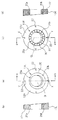
図1、図2、図3(a)および図4〜図7は、本発明に係るボールねじ装置の一実施例を示すものであり、図1はボールねじ装置の要部断面を示す説明図、図2は図1に示す複数組のボールガイド部材からなるボールガイドの分解説明図、図3(a)は図2におけるボールガイド部材の接合分離状態の側面図、図4〜図7は図2における各ボールガイド部材を構成する一対のボールガイド片の接合面の構成をそれぞれ示す分解説明図である。 1, FIG. 2, FIG. 3 (a) and FIGS. 4 to 7 show an embodiment of a ball screw device according to the present invention, and FIG. 1 is an explanatory view showing a cross section of the main part of the ball screw device. 2 is an exploded explanatory view of the ball guide comprising a plurality of sets of ball guide members shown in FIG. 1, FIG. 3A is a side view of the ball guide member joined and separated in FIG. 2, and FIGS. 2 is an exploded explanatory view showing a configuration of a joint surface of a pair of ball guide pieces constituting each ball guide member in FIG.
本実施例におけるボールねじ装置は、第1図に示すように、外周面に螺旋状のねじ溝42を形成したねじ軸40と、このねじ軸40を挿通させるねじ軸挿通孔11を有し、前記ねじ軸40と部分的に螺合するように前記ねじ溝42と対応するボールガイド溝20(図4参照)を形成したボールガイド10と、前記ボールガイド溝20内に配置され前記ねじ軸40のねじ溝42に対し部分的に収容される複数のボール30とを備えた構成からなる。
As shown in FIG. 1, the ball screw device in the present embodiment has a
前記ボールガイド10は、基本的に、図2に示すように、ねじ軸40の軸方向の垂直面に対しねじ軸40のリード角θ(図1参照)と対応する角度θで傾斜する接合面12A、12B〔図3(a)および図4参照〕を形成して、相互に接合するように構成してなる一対のボールガイド片13L、13Rからなる第1のボールガイド部材12、同様に構成してなる一対のボールガイド片15L、15Rからなる第2のボールガイド部材14、同様に構成してなる一対のボールガイド片17L、17Rからなる第3のボールガイド部材16、および同様に構成してなる一対のボールガイド片19L、19Rからなる第4のボールガイド部材18からなる。本発明においては、基本的に前記4組のボールガイド部材12、14、16、18を、それぞれ前記ねじ軸40の軸方向に同軸的に組合せて本体50と蓋体52とからなるボールガイドケーシング内に収納固定して、ボールガイド10を構成することができる。
As shown in FIG. 2, the ball guide 10 basically has a joint surface inclined at an angle θ corresponding to a lead angle θ (see FIG. 1) of the
そこで、本実施例のボールねじ装置においては、例えば図4に示すように、前記第1のボールガイド部材12における一対のボールガイド片13L、13Rの接合面12A、12Bにおいては、複数のボール30を転動自在に収納配置し、前記ねじ軸40のねじ溝42の一部に収容されるようにすると共に前記接合面12A、12B内において一巡して循環するようにしたボールガイド溝20をそれぞれ対称的に刻設した構成からなる。また、前記第2のボールガイド部材14、第3のボールガイド部材16および第4のボールガイド部材18についても、前記第1のボールガイド部材12と同様にして、それぞれ一対のボールガイド片15L、15Rと、17L、17Rと、19L、19Rのそれぞれ接合面14A、14Bと、16A、16Bと、18A、18Bに、それぞれボールガイド溝20が対称的に刻設される(図5、図6、図7参照)。従って、このようにボールガイド部材12、14、16、18を構成することにより、ボールガイド10の成形加工に際し、従来のように高価な専用機を必要とすることなく、簡便かつ容易にして低コストに実現することができる。
Therefore, in the ball screw device of the present embodiment, for example, as shown in FIG. 4, a plurality of
また、本実施例のボールねじ装置においては、図4に示すように、前記第1のボールガイド部材12における一対のボールガイド片13L、13Rの接合面12A、12Bにそれぞれ対称的に刻設するボールガイド溝20は、一対のボールガイド片13L、13Rの傾斜する接合面12A、12Bにおける最大厚みとなる位置Xと最小厚みとなる位置Yとを相互に結ぶ中心線CLに対し、左右対称的に設ける。なお、前記第2のボールガイド部材14、第3のボールガイド部材16および第4のボールガイド部材18についても同様である(図5、図6、図7参照)。
Further, in the ball screw device of the present embodiment, as shown in FIG. 4, they are symmetrically engraved on the
そして、この場合、前記第1のボールガイド部材12における一方のボールガガイド溝20は、前記中心線CL上において相互のボールガイド片13L、13Rが最大厚みとなる位置Xと最小厚みとなる位置Yとが重なるようにして接合するように設定する(図2参照)。また、前記第2のボールガイド部材14、第3のボールガイド部材16および第4のボールガイド部材18についても同様である(図2参照)。
In this case, one
さらに、前記中心線CLの一端側においては、ボール30がねじ軸40に形成したねじ溝42内に部分的に収容されるように形成したボールガイド溝部分20aとし、前記中心線CLの他端側においては、ボール30を循環させる循環路からなるボールガイド溝部分20bとして、それぞれ設けられる。
Further, on one end side of the center line CL, a ball
図1に示す本実施例のボールねじ装置は、5組のボールガイド部材12、14、16、18、12を組合せてボールガイド10を構成したものである。すなわち、それぞれのボールガイド部材12、14、16、18においては、一対のボールガイド片の接合面に形成したボールガイド溝20について、前記ボールガイド片の接合面における前記中心線CLを基準として、ねじ軸40の回転方向にそれぞれ90°の等角度で位置変位させた状態とし(図4ないし図7参照)、これらのボールガイド部材12、14、16、18を順次隣接させて配置するように組合せて、組立てたものである(図2および図1参照)。なお、このようにボールガイド部材12、14、16、18を組合せて組立てる場合、図示例に限定されることなく、例えばそれらの組合せの順番は任意に設定して組合せ、組立てることができる。また、前記ボールガイド部材12、14、16、18を組合せる場合においては、4組のボールガイド部材12、14、16、18の組合せを基本として、それ以上のボールガイド部材を組合せてボールガイド10を組立てることができる。
The ball screw device according to the present embodiment shown in FIG. 1 is configured by combining five
代案として、本発明のボールねじ装置においては、前述したように、一対のボールガイド片からなるボールガイド部材の複数組を組合せて構成してなるボールガイド10は、それぞれのボールガイド部材における一対のボールガイド片の接合面に形成したボールガイド溝20について、ボールガイド片の接合面における前記中心線CLを基準として、ねじ軸の回転方向にそれぞれ120°の等角度で位置変位させた構成とし、これらのボールガイド部材を3組またはそれ以上を12、14、16、18組合せて、組立てることもできる。
As an alternative, in the ball screw device of the present invention, as described above, the ball guide 10 formed by combining a plurality of sets of ball guide members each including a pair of ball guide pieces is a pair of ball guide members. The ball guide
また、本発明のボールねじ装置においては、前記複数組のボールガイド部材12、14、16、18を組合せて構成してなるボールガイド10は、ボールガイドケーシング50、52内に収納固定するに際し、前記ボールガイド10の一端側面または両端側面に、ばね等の弾性部材60を設けて弾力的に保持するように構成することができる(図1参照)。従って、このようにボールガイド10のボールガイドケーシング50、52内への収納固定に際して、弾性部材60を設けることによって、それぞれのボールガイド部材12、14、16、18の接合を適正に保持することができると共に、ボールガイド10に対するねじ軸40のバックラッシュを適正に抑制することができる。
In the ball screw device of the present invention, the ball guide 10 formed by combining the plurality of sets of
さらに、本発明のボールねじ装置においては、一対のボールガイド片からなるボールガイド部材12、14、16、18は、それぞれのボールガイド片13L、13Rと、15L、15Rと、17L、17Rと、19L、19Rの外周部において、ねじ軸40(図1参照)の回転方向にそれぞれ90°(または120°)からなる等角度の位置に、複数組のナット部材12、14、16、18を組合せて位置決めすることができる支持棒(図示せず)を挿通するための挿通孔22を設けた構成とすることができる。従って、このように設けた挿通孔22に対し、適宜支持棒を挿通することによって、複数組のボールガイド部材12、14、16、18を適正に組合せて、ボールガイド10の組立て作業を簡便かつ容易に行うことができる。
Furthermore, in the ball screw device of the present invention, the
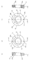
なお、本発明のボールねじ装置において、例えば図8に示すように、一対のボールガイド片13L、13Rからなるボールガイド部材12において、前記一方のボールガイド片13Lの接合面12Aおよびこれに近接ないし一部露呈するようにねじ軸挿通孔11に沿って、ボールの直径寸法に近似する深さ寸法からなるボールガイド溝20a1、20b1 を形成すると共に、このボールガイド溝20a1、20b1 と対応して前記他方のボールガイド片13Rの接合面12Bおよびこれに近接ないし一部露呈するようにねじ軸挿通孔11に沿って、若干の深さ寸法からなるボールガイド溝20a2、20b2 を形成する。そして、他のボールガイド部材14、16、18についても、同様に構成する。このように構成することにより、前記複数組のボールガイド部材からなるボールガイド10を収納固定するボールガイドケーシング50の外周部(図1参照)に対して、強大な荷重が加わった際に、内部におけるボールガイド部材のボールガイド片によって挾持されるボール30を、前記深さ寸法に設定されたボールガイド溝20a1、20b1 内に保持させて、ボールガイド部材の安定性を高めることができる。
In the ball screw device of the present invention, for example, as shown in FIG. 8, in the
以上、本発明の好適な実施例について説明したが、本発明は前述した実施例に限定されることなく、例えば、ねじ軸の任意のリード角θ´に対しは、これに対応して一対のボールガイド片における接合面の傾斜角度θ´を設定すること〔図3(b)参照〕、その他ボールガイドおよびボールガイド部材の形状構成、ボールガイド溝の深さ寸法や全体形状等について、本発明の精神を逸脱しない範囲内において多くの設計変更を行うことができる。 The preferred embodiment of the present invention has been described above. However, the present invention is not limited to the above-described embodiment. For example, for an arbitrary lead angle θ ′ of the screw shaft, a pair of Setting the inclination angle θ ′ of the joint surface in the ball guide piece [see FIG. 3 (b)], other shapes and configurations of the ball guide and ball guide member, depth dimensions and overall shape of the ball guide groove, etc. Many design changes can be made without departing from the spirit of the present invention.
10 ボールガイド
11 ねじ軸挿通孔
12 第1のボールガイド部材
12A、12B 接合面
13L、13R ボールガイド片
14 第2のボールガイド部材
14A、14B 接合面
15L、15R ボールガイド片
16 第3のボールガイド部材
16A、16B 接合面
17L、17R ボールガイド片
18 第4のボールガイド部材
18A、18B 接合面
19L、19R ボールガイド片
20 ボールガイド溝
20a ねじ溝内にボールの収容が可能なボールガイド溝部分
20b 循環路としてのボールガイド溝部分
22 支持棒の挿通孔
30 ボール
40 ねじ軸
42 ねじ溝
50 ボールガイドケーシング本体
52 ボールガイドケーシング蓋体
60 弾性部材
θ ねじ軸のリード角
X 最大厚みとなる位置
Y 最小厚みとなる位置
CL 中心線
DESCRIPTION OF
Claims (5)
前記ボールガイド部材の前記一対のボールガイド片の接合面にそれぞれ対称的に刻設するボールガイド溝は、一対のボールガイド片の傾斜する接合面における最大厚みとなる位置と最小厚みとなる位置とを相互に結ぶ中心線に対し、左右対称的に設けると共に、
前記一方のボールガイド片と他方のボールガイド片との接合面に刻設するボールガイド溝を、前記中心線上において相互にボールガイド片が最大厚みとなる位置と最小厚みとなる位置とが重なるよう接合するように設定して、前記中心線の一端側においてボールがねじ軸に形成したねじ溝内に部分的に収容されるように形成したボールガイド溝部分として形成すると共に、前記中心線の他端側においてボールを循環させる循環路からなるボールガイド溝部分として形成し、
このように構成した複数組の前記ボールガイド部材を、それぞれ前記ねじ軸の軸方向に同軸的にかつ隣接させて組合せて所要のボールガイドケーシング内に収納固定した構成からなることを特徴とするボールねじ装置。 A screw shaft having a helical thread groove formed on the outer peripheral surface, a ball guide having a ball guide groove corresponding to the screw shaft so as to be partially screwed by inserting the screw shaft, and the ball guide groove A plurality of balls that are slidably accommodated and partially accommodated in the thread groove of the screw shaft, and the ball guide is a lead of the screw shaft with respect to a vertical surface in the axial direction of the screw shaft. A ball guide member composed of a pair of ball guide pieces that are joined to each other and formed with a joint surface that is inclined at an angle corresponding to the angle, and the joint surface of the pair of ball guide pieces is in relation to the screw groove of the screw shaft. In a ball screw device formed by symmetrically engraving ball guide grooves that enable circulation of a plurality of partially contained balls ,
The ball guide grooves that are symmetrically engraved on the joint surfaces of the pair of ball guide pieces of the ball guide member, respectively, are a maximum thickness position and a minimum thickness position on the inclined joint surfaces of the pair of ball guide pieces. Are provided symmetrically with respect to the center line connecting the
The ball guide groove formed on the joint surface between the one ball guide piece and the other ball guide piece is arranged such that the position where the ball guide piece has the maximum thickness and the position where the minimum thickness overlap each other on the center line. It is set so as to be joined , and is formed as a ball guide groove portion formed so that the ball is partially accommodated in a screw groove formed on the screw shaft on one end side of the center line. Formed as a ball guide groove portion consisting of a circulation path for circulating the ball on the end side ,
A ball characterized in that a plurality of sets of the ball guide members configured as described above are combined and coaxially and adjacent to each other in the axial direction of the screw shaft , and are housed and fixed in a required ball guide casing. Screw device.
Priority Applications (1)
| Application Number | Priority Date | Filing Date | Title |
|---|---|---|---|
| JP2011055209A JP5419911B2 (en) | 2011-03-14 | 2011-03-14 | Ball screw device |
Applications Claiming Priority (1)
| Application Number | Priority Date | Filing Date | Title |
|---|---|---|---|
| JP2011055209A JP5419911B2 (en) | 2011-03-14 | 2011-03-14 | Ball screw device |
Publications (2)
| Publication Number | Publication Date |
|---|---|
| JP2012189186A JP2012189186A (en) | 2012-10-04 |
| JP5419911B2 true JP5419911B2 (en) | 2014-02-19 |
Family
ID=47082584
Family Applications (1)
| Application Number | Title | Priority Date | Filing Date |
|---|---|---|---|
| JP2011055209A Active JP5419911B2 (en) | 2011-03-14 | 2011-03-14 | Ball screw device |
Country Status (1)
| Country | Link |
|---|---|
| JP (1) | JP5419911B2 (en) |
Families Citing this family (2)
| Publication number | Priority date | Publication date | Assignee | Title |
|---|---|---|---|---|
| JP6475566B2 (en) * | 2015-05-18 | 2019-02-27 | Ntn株式会社 | Ball screw |
| JP6954220B2 (en) * | 2018-04-24 | 2021-10-27 | 日本精工株式会社 | Ball screw |
Family Cites Families (3)
| Publication number | Priority date | Publication date | Assignee | Title |
|---|---|---|---|---|
| JP3387958B2 (en) * | 1993-03-02 | 2003-03-17 | 宗弘 先生 | Ball screw device |
| JP3841561B2 (en) * | 1998-07-29 | 2006-11-01 | 株式会社ジェイテクト | Motion conversion device and power steering device |
| JP2003524121A (en) * | 1999-12-17 | 2003-08-12 | イナーシエツフレル コマンディートゲゼルシャフト | Ball screw |
-
2011
- 2011-03-14 JP JP2011055209A patent/JP5419911B2/en active Active
Also Published As
| Publication number | Publication date |
|---|---|
| JP2012189186A (en) | 2012-10-04 |
Similar Documents
| Publication | Publication Date | Title |
|---|---|---|
| JP2001263445A (en) | Retainer for roller, straight guide device using it, and roller screw | |
| JP5419911B2 (en) | Ball screw device | |
| JPWO2013183763A1 (en) | Linear motion bearing with outer cylinder divided into three | |
| JP2006046644A (en) | Recirculation linear ball bearing | |
| JPWO2010013706A1 (en) | Screw device | |
| JP2013029116A (en) | Motion guide device | |
| JP6187109B2 (en) | Ball screw | |
| JPH0629554Y2 (en) | Ball screw | |
| JP3214017U (en) | Roller spline assembly | |
| JP2005188720A (en) | Ball spline | |
| US20170089391A1 (en) | Cage for a ball bearing provided with a wire and added interposed parts | |
| JP3121911U (en) | Combination back rail for linear guideway | |
| TW201925651A (en) | Ball screw spline | |
| TWM554527U (en) | Roller spline assembly | |
| TWM609095U (en) | Circulating planetary roller screw | |
| JP5872398B2 (en) | Rolling guide device | |
| WO2015033813A1 (en) | Motion guide device | |
| JP2008019974A (en) | Thrust ball bearing cage | |
| JP2018096539A (en) | Ball nut member and ball screw shaft of ball screw device | |
| JP2015143561A (en) | ball screw device | |
| JP5318894B2 (en) | Circulation unit and ball screw using the same | |
| JP6561205B2 (en) | Slider and slide device | |
| US11480236B2 (en) | Ball screw device | |
| JP2008138840A (en) | Slider for linear guide | |
| JP6547429B2 (en) | Ball screw |
Legal Events
| Date | Code | Title | Description |
|---|---|---|---|
| A977 | Report on retrieval |
Free format text: JAPANESE INTERMEDIATE CODE: A971007 Effective date: 20130124 |
|
| A131 | Notification of reasons for refusal |
Free format text: JAPANESE INTERMEDIATE CODE: A131 Effective date: 20130205 |
|
| A521 | Request for written amendment filed |
Free format text: JAPANESE INTERMEDIATE CODE: A523 Effective date: 20130408 |
|
| TRDD | Decision of grant or rejection written | ||
| A01 | Written decision to grant a patent or to grant a registration (utility model) |
Free format text: JAPANESE INTERMEDIATE CODE: A01 Effective date: 20131112 |
|
| A61 | First payment of annual fees (during grant procedure) |
Free format text: JAPANESE INTERMEDIATE CODE: A61 Effective date: 20131119 |
|
| R150 | Certificate of patent or registration of utility model |
Ref document number: 5419911 Country of ref document: JP Free format text: JAPANESE INTERMEDIATE CODE: R150 |
|
| S531 | Written request for registration of change of domicile |
Free format text: JAPANESE INTERMEDIATE CODE: R313531 |
|
| R350 | Written notification of registration of transfer |
Free format text: JAPANESE INTERMEDIATE CODE: R350 |
|
| R250 | Receipt of annual fees |
Free format text: JAPANESE INTERMEDIATE CODE: R250 |
|
| R250 | Receipt of annual fees |
Free format text: JAPANESE INTERMEDIATE CODE: R250 |
|
| S531 | Written request for registration of change of domicile |
Free format text: JAPANESE INTERMEDIATE CODE: R313531 |
|
| R360 | Written notification for declining of transfer of rights |
Free format text: JAPANESE INTERMEDIATE CODE: R360 |
|
| R250 | Receipt of annual fees |
Free format text: JAPANESE INTERMEDIATE CODE: R250 |
|
| R360 | Written notification for declining of transfer of rights |
Free format text: JAPANESE INTERMEDIATE CODE: R360 |
|
| R371 | Transfer withdrawn |
Free format text: JAPANESE INTERMEDIATE CODE: R371 |
|
| S531 | Written request for registration of change of domicile |
Free format text: JAPANESE INTERMEDIATE CODE: R313531 |
|
| R350 | Written notification of registration of transfer |
Free format text: JAPANESE INTERMEDIATE CODE: R350 |
|
| R250 | Receipt of annual fees |
Free format text: JAPANESE INTERMEDIATE CODE: R250 |
|
| S111 | Request for change of ownership or part of ownership |
Free format text: JAPANESE INTERMEDIATE CODE: R313113 |
|
| S533 | Written request for registration of change of name |
Free format text: JAPANESE INTERMEDIATE CODE: R313533 |
|
| R350 | Written notification of registration of transfer |
Free format text: JAPANESE INTERMEDIATE CODE: R350 |
|
| R250 | Receipt of annual fees |
Free format text: JAPANESE INTERMEDIATE CODE: R250 |
|
| R250 | Receipt of annual fees |
Free format text: JAPANESE INTERMEDIATE CODE: R250 |
|
| R250 | Receipt of annual fees |
Free format text: JAPANESE INTERMEDIATE CODE: R250 |