JP5416632B2 - mechanical pencil - Google Patents
mechanical pencilInfo
- Publication number
- JP5416632B2 JP5416632B2 JP2010071792A JP2010071792A JP5416632B2 JP 5416632 B2 JP5416632 B2 JP 5416632B2 JP 2010071792 A JP2010071792 A JP 2010071792A JP 2010071792 A JP2010071792 A JP 2010071792A JP 5416632 B2 JP5416632 B2 JP 5416632B2
- Authority
- JP
- Japan
- Prior art keywords
- core tank
- tank
- chuck
- mechanical pencil
- lead
- Prior art date
- Legal status (The legal status is an assumption and is not a legal conclusion. Google has not performed a legal analysis and makes no representation as to the accuracy of the status listed.)
- Active
Links
Images
Landscapes
- Mechanical Pencils And Projecting And Retracting Systems Therefor, And Multi-System Writing Instruments (AREA)
Description
本発明は、軸筒を上下に振ることにより芯を繰り出すことができるようにしたシャープペンシルに関するものである。 The present invention relates to a mechanical pencil capable of feeding a lead by shaking a shaft cylinder up and down.
軸筒内に収納した重量体を上下動させてチャック部を前方(軸筒の先端方向)へ移動させたり、ノック操作によってチャック部を前進させて芯を繰り出すようにしたシャープペンシルが広く用いられている(例えば特許文献1参照)。一般的に、このようなシャープペンシルは、軸筒内に軸方向に移動可能に収納した芯タンクの前端にチャックを固着し、チャックスプリングで該芯タンクを後方に付勢し、この芯タンクに取り付けたコネクターに突部を形成しこの突部に当るよう芯タンクの外周に重量体を摺動可能に嵌挿してある。一方、この芯タンクの後方には、芯タンクと別に形成したクリップホルダーを挿入固定し、このクリップホルダーに消しゴム支えを軸方向に移動可能に設け、この消しゴム支えに消しゴム及びノブを取り付け、消しゴム支えのフランジ部とクリップホルダー間にノックスプリングを設けて消しゴム支えを後方に付勢している。 A mechanical pencil is widely used in which the weight body stored in the shaft cylinder is moved up and down to move the chuck part forward (toward the tip of the shaft cylinder), or the chuck part is advanced by a knocking operation so that the core is extended. (For example, refer to Patent Document 1). Generally, such a mechanical pencil has a chuck fixed to the front end of a lead tank that is housed in an axial cylinder so as to be movable in the axial direction, and the lead tank is urged rearward by a chuck spring. A protrusion is formed on the attached connector, and a weight body is slidably fitted on the outer periphery of the core tank so as to contact the protrusion. On the other hand, a clip holder formed separately from the lead tank is inserted and fixed behind the lead tank, and an eraser support is provided on the clip holder so as to be movable in the axial direction, and an eraser and a knob are attached to the eraser support. A knock spring is provided between the flange portion and the clip holder to urge the eraser support backward.
上記の構成により、軸筒を上下動すると重量体が芯タンクの突起に当って該芯タンクを前進させ、芯を繰り出すことができる。また、ノブを介して消しゴム支えをノックすると、該消しゴム支えの内端が芯タンクの後端に当って該芯タンクを前進させ、芯を繰り出すことができる。このように、従来のこの種のシャープペンシルでは、芯の繰り出しに際し、常に芯タンク全体を前進させることにより芯を繰り出すよう構成されている。 With the above configuration, when the shaft cylinder is moved up and down, the weight body hits the protrusion of the lead tank, and the lead tank can be advanced to feed the lead. Further, when the eraser support is knocked via the knob, the inner end of the eraser support hits the rear end of the lead tank, and the lead tank can be advanced to feed the lead. As described above, the conventional mechanical pencil of this type is configured to feed the lead by always moving the whole lead tank forward when the lead is drawn.
上記のような構成のため、従来のシャープペンシルでは、芯タンクの他に別体にクリップホルダーや消しゴム支え等を形成しなければならないから、部品点数が多くなり、また軸筒の前端側からチャックやチャックスプリング、コネクター等を組み込んだメカ部を挿入し、後端側から消しゴム支えやノックスプリングを組み込んだクリップホルダー部を軸筒に挿入固定しなければならないので、組立も面倒であり、複雑で経済的に得にくいという問題があった。 Due to the above configuration, the conventional mechanical pencil requires a separate clip holder and eraser support in addition to the core tank, which increases the number of parts and chucks from the front end side of the shaft cylinder. And a mechanism that incorporates a chuck spring, connector, etc. must be inserted, and a clip holder part that incorporates an eraser support and knock spring must be inserted and fixed from the rear end side. There was a problem that it was difficult to obtain economically.
本発明の解決課題は、軸筒を上下に振ったり、軸筒の後端から突出する芯タンクをノックすることにより芯を繰り出すようにしたシャープペンシルにおいて、部品点数を少なくし、組立工程も殆ど軸筒の後端から挿入固定して簡単に組立できるようにしたシャープペンシルを提供することである。 The problem to be solved by the present invention is to reduce the number of parts and to assemble almost all of the assembly processes in a mechanical pencil that is fed out by swinging the shaft cylinder up and down or knocking the core tank protruding from the rear end of the shaft cylinder. It is to provide a mechanical pencil which can be easily assembled by being inserted and fixed from the rear end of a shaft cylinder.
本発明によれば、軸筒内に軸方向に移動可能に収納した芯タンクと、該芯タンクを後方に付勢するよう芯タンクの前部と軸筒の内面間に設けたノックスプリングと、該芯タンクの周囲に軸方向に移動可能に遊嵌した重量体と、上記芯タンクにより移動するよう該芯タンクの前部に保持され芯を把持するチャックを固着したチャックガイドと、該チャックガイドを弱い力で後方に付勢するようチャックガイドの前部と軸筒の内面間に設けたチャックスプリングと、該芯タンクに設けられ芯タンクの後退動を制限するよう軸筒に形成した窓に係合する係止突起を具備し、上記チャックガイドは、上記重量体が前進した際該重量体が当接可能にかつ該重量体により芯タンクから独立して前方に移動するよう軸方向に移動可能に上記芯タンクに連結されていることを特徴とするシャープペンシルが提供され、上記課題が解決される。 According to the present invention, a lead tank accommodated in the shaft cylinder so as to be movable in the axial direction, a knock spring provided between the front portion of the lead tank and the inner surface of the shaft cylinder so as to bias the lead tank rearward, A weight body loosely fitted around the lead tank so as to be movable in the axial direction, a chuck guide to which a chuck that holds the lead held by the lead tank so as to be moved by the lead tank is fixed, and the chuck guide A chuck spring provided between the front portion of the chuck guide and the inner surface of the shaft cylinder so as to bias it backward with a weak force, and a window formed on the shaft cylinder to limit the backward movement of the core tank. The chuck guide has an engaging projection, and the chuck guide moves in an axial direction so that the weight body can come into contact with the weight body when it moves forward and moves forward independently of the core tank by the weight body. Connected to the core tank Mechanical pencil, characterized in that it has been provided, the problems are solved.
また、本発明によれば、上記チャックガイドは芯タンク壁が入り込む挿入間隙を開けて対向する内筒と外筒および該内筒、外筒を連結する連結片を有し、上記芯タンクには上記連結片が入り込む受溝が形成され、該受溝と該チャックガイドの連結片の間には、芯タンクが後退しているとき遊び間隙が形成され、上記芯タンクは衝撃吸収片を有している上記シャープペンシルが提供される。 According to the present invention, the chuck guide has an inner cylinder and an outer cylinder facing each other with an insertion gap into which the core tank wall enters, and a connecting piece for connecting the inner cylinder and the outer cylinder. A receiving groove into which the connecting piece enters is formed, and a play gap is formed between the receiving groove and the connecting piece of the chuck guide when the lead tank is retracted, and the lead tank has a shock absorbing piece. A mechanical pencil is provided.
本発明は、上記のように構成され、軸筒内に軸方向に移動可能に収納した芯タンクと、該芯タンクを後方に付勢するよう芯タンクの前部と軸筒の内面間に設けたノックスプリングと、該芯タンクの周囲に軸方向に移動可能に遊嵌した重量体と、上記芯タンクにより移動するよう該芯タンクの前部に保持され芯を把持するチャックを固着したチャックガイドと、該チャックガイドを弱い力で後方に付勢するようチャックガイドの前部と軸筒の内面間に設けたチャックスプリングと、該芯タンクに設けられ芯タンクの後退動を制限するよう軸筒に形成した窓に係合する係止突起を具備し、上記重量体が前進した際該重量体が上記チャックガイドに当接しかつ該重量体により芯タンクから独立してチャックガイドが前方に移動するよう軸方向に移動可能に上記芯タンクにチャックガイドを連結したから、軸筒を上下動させるとチャックガイドが前進して芯を繰り出すことができ、組立の際、チャックガイドや重量体を組み込んだ芯タンクを軸筒の後端から挿入組み付けするだけで簡単に組立でき、従来のこの種のシャープペンシルのように、芯タンクの他に別体にクリップホルダーや消しゴム支えを用意したり、軸筒の前部からメカ部を組み込んだ後、軸筒の後部からクリップホルダー部を組み込んだりしなくてもよいので、構成が著しく簡素化され、組立も容易で経済的に得ることができる。 The present invention is configured as described above, and is provided between a front portion of the lead tank and the inner surface of the shaft tube so as to urge the lead tank rearward so as to be axially movable in the shaft tube. A chuck guide to which a knock spring, a weight body loosely fitted around the lead tank so as to be movable in the axial direction, and a chuck for holding the lead held by the lead tank so as to be moved by the lead tank are fixed. A chuck spring provided between the front portion of the chuck guide and the inner surface of the shaft cylinder so as to urge the chuck guide rearward with a weak force, and a shaft cylinder provided in the core tank to limit the backward movement of the core tank The weight guide contacts the chuck guide when the weight body moves forward, and the chuck guide moves forward independently of the lead tank by the weight body. Move in the axial direction Since the chuck guide is connected to the core tank, the chuck guide can be advanced by moving the shaft cylinder up and down, and the core can be fed out. It is easy to assemble by simply inserting it from the rear end. Like this type of conventional mechanical pencil, in addition to the lead tank, a clip holder and eraser support can be prepared separately. Since the clip holder part does not have to be assembled from the rear part of the shaft cylinder after the part is incorporated, the configuration is remarkably simplified and the assembly can be obtained easily and economically.
また、上記チャックガイドに芯タンク壁が入り込む挿入間隙をあけて対向する内筒と外筒および該内筒、外筒を連結する連結片を設け、上記芯タンクに上記連結片が入り込む受溝を形成し、該受溝と該チャックガイドの連結片の間に、芯タンクが後退しているとき遊び間隙を存するように構成すると、芯タンクの後部に取り付けた消しゴム等を使用する際、芯タンクが多少前方に押圧されても、チャックガイドが移動されず、芯が不用意に突出しないようにできる。その上、上記芯タンクに衝撃吸収片を設け、該衝撃吸収片として芯タンクの外面に起立片を立ち上げると、衝撃吸収片の構成が簡単であり、別部品や組み込み工程が不要となって、より経済的に得ることができる。 In addition, an inner cylinder and an outer cylinder facing each other with an insertion gap through which the core tank wall enters the chuck guide and a connecting piece for connecting the inner cylinder and the outer cylinder are provided, and a receiving groove for entering the connecting piece into the core tank is provided. When the eraser or the like attached to the rear part of the lead tank is used, a lead tank is formed between the receiving groove and the connecting piece of the chuck guide. Even if it is pressed slightly forward, the chuck guide is not moved, and the core can be prevented from inadvertently protruding. In addition, if a shock absorbing piece is provided in the core tank, and the standing piece is raised on the outer surface of the core tank as the shock absorbing piece, the structure of the shock absorbing piece is simple, and no separate parts or assembly steps are required. Can be obtained more economically.
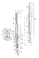
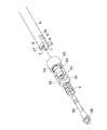
図1は、本発明のシャープペンシルの一実施例を示し、軸筒1の前端にはブレーカーゴム、弾性保持片等の芯仮保持機構2を設けたテーパー3が連結され、該軸筒1内には、軸方向に移動可能に筒状の芯タンク4が収納されている。該芯タンク4の前部には、図2(A)に示すように、受溝(割り溝)5を対向して設けることにより二つの挿入片6が形成され、該挿入片6の先端に設けたスプリング受7と軸筒の内面に形成した段部8の間に、芯タンク4を後方に付勢するノックスプリング9が設けられる。上記スプリング受は、図に示す実施例では小さな突片に形成してあるが、凹み部であってもよく、挿入片の数は適宜に形成することができる。なお、ノックスプリングの荷重は、例えば500g程度の高荷重に設定されている。
FIG. 1 shows an embodiment of the mechanical pencil of the present invention. A
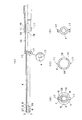
上記芯タンク4の後部に形成した拡径部10には係止突起11が設けられている。該係止突起11は、図3に示すように、芯タンクを軸筒に挿入する際、軸筒内に入り込んで該軸筒に形成した軸方向に延びる窓12内に容易に突出するよう前端に傾斜面13が形成され、芯タンクが後退するとき、該窓12の縁部14に確実に係合して後退動を制限するよう後端に起立面15が形成されている。また、該芯タンクを軸筒の後端から挿入して軸筒に装着する際、芯タンク4が内方にたわんで上記係止突起11を容易に上記窓12内に突出させることができるよう芯タンク4のたわみを許容するための逃げ孔16が上記拡径部10に形成され、該拡径部の少し前方の芯タンクの中間部には衝撃吸収片17として芯タンクと一体的に形成された起立片が突出している。なお、該芯タンク4の拡径部10の後端には消しゴム18が嵌着されている。
A
上記芯タンク4の周囲には、軸筒1を上下動した際、軸方向に移動するよう筒状の金属パイプ等で構成した重量体19が遊嵌されている。上記芯タンク4の拡径部10の手前には、重量体19が当接したとき衝撃を吸収、緩和できるよう上記起立片のような衝撃吸収片17が設けられているが、起立片に代えて、ゴム材料、エラストマー材料等の弾性材料で芯タンクとは別体に形成した部材を芯タンクに取り付けて衝撃を吸収することもできる。図2に示すように芯タンクの外面から一体的に立ち上がる形状の上記起立片を設けると、重量体が該起立片に当ったときに該起立片の先端が少し弾性的に傾斜して衝撃を吸収することができるので、部品点数が減少され、組立も容易となり、一層好ましい。
Around the
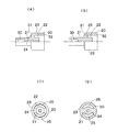
上記芯タンク4の前部には、チャックガイド20が軸方向に移動可能に取り付けられている。図4を参照し、該チャックガイド20には、上記芯タンク4の内面に対向する内筒21と、該内筒21との間に芯タンク壁が入り込む挿入間隙22を存して芯タンクの外面に対向する外筒23と、該内筒21と外筒23を連結しかつ上記芯タンク4の受溝5内に入り込む幅の連結片24が形成され、上記挿入間隙22の前部には、上記芯タンク4の前部に形成した挿入片6が貫通するよう貫通孔25が設けられ、軸筒1の内面に形成した段部8との間にはチャックガイド20を後方に付勢するチャックスプリング26が設けられている。この構成により、該チャックガイド20は、挿入片6に沿って軸方向に移動可能であり、好ましくは、組立に際し、芯タンク4に装着後、重量体が自重でチャックガイドに軽く当る程度では芯タンクから簡単に抜け落ちない程度に貫通孔の縁部にかみ合うよう上記貫通孔を通って前方に延びる挿入片6の外周にはチャックガイドの貫通孔の縁部に当接可能な隆起部27が形成されている。このためには、該隆起部部分を内方に押し込んだ状態で挿入片を上記貫通孔に挿通し、貫通後、隆起部部分が弾性作用でもとに戻って上記のように係合できるようにすればよい。
A
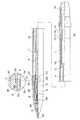
上記チャックガイド20の内筒21の前方内面には、クラッチ28を嵌着したチャック29の基端を挿入固定できるようチャック固定部30が形成されている。該クラッチ28はチャックガイド20が後退するとき、公知のように軸筒1の内方先端に係止され、チャック29を締め付ける。また、上記外筒23の前端部には支承面31が形成され、該支承面31には、上述したように軸筒の段部8との間に設けた上記チャックスプリング26が当接する。このチャックスプリング26は、上記ノックスプリング9より弱い力のスプリングであり、例えば、150g程度の低荷重に設定される。外筒23の後端部には、上記重量体19が当接するよう当接面32が形成されている。
A
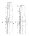
上記の構成により、チャックスプリング26、ノックスプリング9を軸筒の後端から軸筒内に挿入し、芯タンク4の中間部に重量体19を遊嵌するとともに前部に形成した挿入片6をチャックガイド20の貫通孔25に貫挿させてチャックガイド20を芯タンク4に装着し、この芯タンクの組立体を軸筒の後端から挿入し、係止突起11を窓12に係合させれば、組み付けが終了する。その後、軸筒の前方からチャック29をチャックガイド20に差し込んだり、消しゴム18やテーパー3を取り付ければよい。このように殆どの工程を軸筒の後端側からできるので、組み立てが簡単である。なお、組立状態で、芯タンクが後退しているとき、上記チャックガイド20の連結片24と芯タンク1の受溝5の底部33間には、図1に示すように若干の遊び間隙Sを生じるようにしてある。この遊び間隙Sは、芯タンク4の後端に設けた消しゴム18を通常のように使用した際、芯タンク4が前方に多少押し込まれる程度では、連結片24に受溝の底部33が当らないような寸法にするとよい。
With the above configuration, the
そして、ノック操作で芯34を繰り出すには、図6に示すように、通常のシャープペンシルと同じように芯タンク4の後端を前方にノックすると、ノックスプリング9に抗して芯タンク4が前進し、受溝の底部33がチャックガイド20の連結片24に当接し、該チャックガイド20がチャックスプリング26に抗して前進するから、該チャックガイド20に固着したチャック29が前進して公知のように芯34を繰り出すことができる。ノックを停止すると、芯タンクは後退するが、この後退動は係止突起11が窓12の縁部14に当ることにより制限される。芯34を後退させる場合は、公知のように芯タンク4をノックしながら芯34の先端をテーパー3内に押戻せばよい。
And in order to let out the
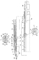
上記軸筒1を上下動させると、図7に示すように、重量体19が前進して上記チャックガイド20の外筒23の後端部に設けた当接面32に当り、該チャックガイド20をチャックスプリング26に抗して前進させることができるから、上記ノック操作の場合と同様に芯34が繰り出される。なお、この場合、チャックガイド20は芯タンク4から独立しているので、芯タンク4は前進せずに、チャックガイド20だけが移動する。
When the
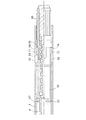
上記重量体19が芯タンク4の拡径部10に当るような位置まで軸筒1内で上下動すると、拡径部の手前に設けた衝撃吸収片17に当るから、芯タンク4に消しゴム18が外れてしまうような大きな衝撃を与えないようにすることができる。そのため、図8に示すように繰出形式の消しゴムユニット35やその他の適宜の部材を芯タンク4の後端部に装着しても、振動、衝撃等で該消しゴムユニット35等が外れないようにすることができる。
When the
1 軸筒
3 テーパー
4 芯タンク
5 受溝
6 挿入片
9 ノックスプリング
10 拡径部
11 係止突起
12 窓
17 衝撃吸収片
19 重量体
20 チャックガイド
21 内筒
22 挿入間隙
23 外筒
24 連結片
25 貫通孔
26 チャックスプリング
29 チャック
30 チャック固定部
DESCRIPTION OF
Claims (8)
Priority Applications (1)
| Application Number | Priority Date | Filing Date | Title |
|---|---|---|---|
| JP2010071792A JP5416632B2 (en) | 2010-03-26 | 2010-03-26 | mechanical pencil |
Applications Claiming Priority (1)
| Application Number | Priority Date | Filing Date | Title |
|---|---|---|---|
| JP2010071792A JP5416632B2 (en) | 2010-03-26 | 2010-03-26 | mechanical pencil |
Publications (2)
| Publication Number | Publication Date |
|---|---|
| JP2011201199A JP2011201199A (en) | 2011-10-13 |
| JP5416632B2 true JP5416632B2 (en) | 2014-02-12 |
Family
ID=44878415
Family Applications (1)
| Application Number | Title | Priority Date | Filing Date |
|---|---|---|---|
| JP2010071792A Active JP5416632B2 (en) | 2010-03-26 | 2010-03-26 | mechanical pencil |
Country Status (1)
| Country | Link |
|---|---|
| JP (1) | JP5416632B2 (en) |
Family Cites Families (5)
| Publication number | Priority date | Publication date | Assignee | Title |
|---|---|---|---|---|
| JPH0439028Y2 (en) * | 1986-11-14 | 1992-09-11 | ||
| JPH0432307Y2 (en) * | 1987-06-12 | 1992-08-03 | ||
| JPH0258983U (en) * | 1988-10-17 | 1990-04-27 | ||
| JPH0420490U (en) * | 1990-06-11 | 1992-02-20 | ||
| JP5323523B2 (en) * | 2009-02-10 | 2013-10-23 | 株式会社パイロットコーポレーション | A swing-out mechanical pencil for composite writing instruments |
-
2010
- 2010-03-26 JP JP2010071792A patent/JP5416632B2/en active Active
Also Published As
| Publication number | Publication date |
|---|---|
| JP2011201199A (en) | 2011-10-13 |
Similar Documents
| Publication | Publication Date | Title |
|---|---|---|
| US5009533A (en) | Propelling pencil with cushion sleeve | |
| RU2008143346A (en) | Lancet assembly | |
| JP4705428B2 (en) | Automatic mechanical pencil and its assembly method | |
| JP2009208424A (en) | Retractable mechanical pencil | |
| JP5416632B2 (en) | mechanical pencil | |
| JP4676830B2 (en) | Writing instrument | |
| KR101295009B1 (en) | Anchoring device for control cable of vehicle | |
| JP6555948B2 (en) | Swing-out mechanical pencil | |
| JP3139755U (en) | Knock-type writing instrument | |
| US10603948B2 (en) | Mechanical pencil | |
| JP6080898B2 (en) | mechanical pencil | |
| JP2009000826A (en) | Intrusive writing instrument | |
| JP5671913B2 (en) | mechanical pencil | |
| JP5889574B2 (en) | Side knock type writing instrument | |
| JP4293803B2 (en) | Swing-out mechanical pencil | |
| JP6356532B2 (en) | Writing instrument | |
| JP5705653B2 (en) | Swing-out mechanical pencil | |
| JP5339618B2 (en) | Swing-out mechanical pencil | |
| JP7255857B2 (en) | Mechanical pencil with breakage prevention mechanism | |
| JP6448949B2 (en) | Knock-type ballpoint pen | |
| JP2004232742A (en) | Shaft connection structure | |
| JP5525427B2 (en) | mechanical pencil | |
| JP3653699B2 (en) | Knock-type writing instrument | |
| JP2012240406A (en) | Shaking-out type mechanical pencil | |
| JP3933059B2 (en) | Intrusive writing instrument |
Legal Events
| Date | Code | Title | Description |
|---|---|---|---|
| A621 | Written request for application examination |
Free format text: JAPANESE INTERMEDIATE CODE: A621 Effective date: 20130117 |
|
| A977 | Report on retrieval |
Free format text: JAPANESE INTERMEDIATE CODE: A971007 Effective date: 20131009 |
|
| TRDD | Decision of grant or rejection written | ||
| A01 | Written decision to grant a patent or to grant a registration (utility model) |
Free format text: JAPANESE INTERMEDIATE CODE: A01 Effective date: 20131022 |
|
| A61 | First payment of annual fees (during grant procedure) |
Free format text: JAPANESE INTERMEDIATE CODE: A61 Effective date: 20131115 |
|
| R150 | Certificate of patent or registration of utility model |
Ref document number: 5416632 Country of ref document: JP Free format text: JAPANESE INTERMEDIATE CODE: R150 |
|
| R250 | Receipt of annual fees |
Free format text: JAPANESE INTERMEDIATE CODE: R250 |
|
| R250 | Receipt of annual fees |
Free format text: JAPANESE INTERMEDIATE CODE: R250 |
|
| R250 | Receipt of annual fees |
Free format text: JAPANESE INTERMEDIATE CODE: R250 |
|
| R250 | Receipt of annual fees |
Free format text: JAPANESE INTERMEDIATE CODE: R250 |
|
| R250 | Receipt of annual fees |
Free format text: JAPANESE INTERMEDIATE CODE: R250 |
|
| R250 | Receipt of annual fees |
Free format text: JAPANESE INTERMEDIATE CODE: R250 |
|
| R250 | Receipt of annual fees |
Free format text: JAPANESE INTERMEDIATE CODE: R250 |
|
| R250 | Receipt of annual fees |
Free format text: JAPANESE INTERMEDIATE CODE: R250 |
|
| R250 | Receipt of annual fees |
Free format text: JAPANESE INTERMEDIATE CODE: R250 |
|
| R250 | Receipt of annual fees |
Free format text: JAPANESE INTERMEDIATE CODE: R250 |